无线交互系统主机说明书(中文)
Clear-Com WBS-670 680 无线通信系统用户手册说明书
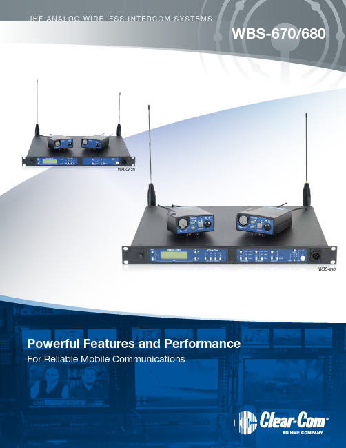
U H F A n A L O g W I R E L E S S I n T E R C O M S y S T E M SWBS-670/680WBS-670WBS-680WIRElESS InTERCOM SySTEMSWBS-670 SInGlE-CHAnnEl WIRElESSThe WBS-670 1RU, rack-mountable base station supports up to four full-duplex wireless beltpacks.System Features:• Full talk/listen headset at the base• Rear panel connections allow system expansionTransmit Bands Receive BandsSingle Channel Wireless Intercom System (WBS-670) Frequency Band Options: A2, B4, C3, C6, g9 Two-Channel Wireless Intercom System (WBS-680) Frequency Band Options: A2, B4, C3, C6, E884 Clear-Com WBSClear-Com WBS 5OVerVieWWBS-680/WBS-670 Base StationWtr-680/Wtr-670 BeltpacksrF Frequency range 518-608MHz, 614-686MHz in 18MHz tX and RX bands WBs-670: G9 band, 796-814MHz tx, Germany only518 - 608MHz, 614 - 686MHz in 18MHz tX and RX bands WtR-670: G9 band, 844-862MHz tx, Germany onlypower requirement 100-240VAC, 50-60Hz, ieC receptacle6 Alkaline “AA” Cells (niMH optional)typical Battery Life alkalinen/A 14 Hours (Continuous duty with talk light on)typical Battery Life - nickel Metal Hydride (1500 mah)n/A 11 Hours (Continuous duty with talk light on)current draw n/A140mA (Push-to-talk, talk on)temperature range -4°F to 140°F (20°C to 55°C)-4°F to 140°F (20°C to 55°C)dimensions 19.0” W x 1.72” H x 14.0” d (48.3cm x 4.4cm x 35.6cm) 3.75” W x 5.05” H x 1.65” d (9.5cm x 12.8cm x 4.2cm)WeightWBs-680: 7lbs. 2oz. (3.24kg) WBs-670: 6lbs. 15oz. (3.15kg)16oz. (0.454kg) with batteries 15oz. (0.425kg) with batteriestransmit antenna 1/2 Wave (supplied), tnC Male Connector 1/4 Wave (supplied), screw type receiver antenna 1/2 Wave (supplied), tnC Male Connector1/4 Wave (supplied), screw typeFcc idB5dM514 B5dM515Frequency response 300Hz - 8,000Hz 300Hz - 8,000HzFour-Wire input Level Adjustable (2Vrms typical)n/A Four-Wire OutputLevel Adjustable (2Vrms typical)n/A clear-com ® partyline Levels input/output Level Adjustable (1Vrms typical),Line impedance 200W n/A rtS ® partyline Levels input/output Level Adjustable (0.775Vrms typical),Line impedance 200W n/A telex ® partyline Levels input/output Level Adjustable (1 Vrms typical),Line impedance 300Wn/A auxiliary input Adjustable (2Vrms typical)n/A auliliary OutputAdjustable (2Vrms typical into 600W) (at rated deviation)n/A Stage announce Output (WBS-680 only)internally Adjustable (1Vrms typical at rated deviation into 100KW)n/A Stage announce relay (WBS-680 only)dry contact, rated at 1Amp, 24V Max. / n/An/AreceiVerWBS-680/WBS-670 Base StationWtr-680/Wtr-670 Beltpackstype dual Conversion superheterodyne, synthesized, FM,720 channelsdual Conversion superheterodyne, synthesized, FM,720 channelsrF Sensitivity <0.7mV for 12dB sinAd<0.7mV for 12dB sinAdSignal-to-noise ratio 95dB 95dB iF Selectivity 3dB at 230KHz 3dB at 230KHz image rejection 70dB or better70dB or betterSquelch quieting 95dB 95dB rF Frequency Stability 0.005%0.005%distortion<1% at full deviation<1% at full deviationLocal Headset Output 40mW output into 600W (1% distortion)40mW output into 600W (1% distortion)Fcc acceptancenotification under FCC Part 15notification under FCC Part 15tranSMitterWBS-680/WBS-670 Base StationWtr-680/Wtr-670 Beltpacks typesynthesized, 720 channelssynthesized, 720 channels transmit power WBs-680: 100mW max. (High), 10mW (normal) WBs-670: 50mW max. (High), 5mW (normal)WtR-680/WtR-670: 50mW max. (auto-power reduction when close to base)rF Frequency Stability 0.005%0.005%Modulation FM, 40KHz deviation FM, 40KHz deviation Modulation LimiterPeak-Responding Compressor Peak-Responding Compressor Modulation Frequency range 300Hz -8,000Hz +-2dB300Hz -8,000Hz +-2dBMicrophone audio input 30W - 3,500W30W - 3,500WMicrophone input Sensitivity 9mV9mVradiated Harmonics & Spurious exceeds FCC specifications exceeds FCC specifications Fcc acceptancetype accepted under FCC Part 74type accepted under FCC Part 74WTR4CThe WTR4C has the same features as the WTR1C, except that the WTR4C can charge up to four batteries simultaneously.TECHnICAl SPECIFICATIOnSBc-800nM4 & Bc-800nM Battery cHarGerSphysical characteristics Bc-800nM4Bc-800nMproduct dimensions13” (33cm) W x 1.7” (4.5cm)H x 7” (17.8cm) d 3” (7.62cm) W x 3.5” (8.89cm)H x 6” (15.24cm) dproduct Weight4lbs (1.5kg) without battery adapters1lb, 6oz (0.62kg)Shipping dimensions11.5” (29.2cm) W x 10.5” (26.7cm)H x 18.5” (47cm) d 7” (17.8cm) W x 4.5” (11.43cm)H x 7” (17.8cm) dShipping Weight10lbs, 9oz (4.8kg) with battery adapters,power supply, & rechargeable battery packs 2lbs, 10oz (1.2kg) with rechargeable battery pack & power supplyMaterial ABs KJW fire retardant plastic, textured ABs KJW fire retardant plastic, texturedFeatUreSconditioning cycle Provides built-in maintenance capability to maximize battery cycle lifeStatus indicators‘Charging’, ‘Ready’, ‘Rejected’ (dead battery), ‘Conditioning Cycle’and ‘Power Led’ indicators make the BC-800nM simple and easy to use intelligent charging• Optimizes the battery • Battery can remain in the charger indefinitely• Maintains battery at peak capacityrapid charge capability Charges in less than 2 hoursUSer enVirOnMenteSd8KV continuous contact discharge; 15KV from air to all surfaces without contact Humidity95% relative humidity (non-condensing)drop unit functions normally after 4ft./1.2m drop to concreteStorage temperature-40° to 122oF/-40° to 50°COperating temperature32° to 122°F/0o to 50°Cpower Supply BC-800nM4: (universal): 90V-230VAC, 50/60Hz output: 15VdC, 5A or 24VdC, 4.5ABC-800nM: (universal): 90V-230VAC, 50/60Hz output: 15VdC, 1.5A or 24VdC, 1.3A Safety Standards Charger & power supply uL listed (uL 1950), CsA Certified (C 22.2 no. 223);Compliant to FCC part 15 Class A and Ce Marking(electromagnetic Compatibility) directive 89/336/eeC and Low Voltage directive 73/23/eeC;C15PR-22 Class BperFOrMance cHaracteriSticSrapid charge Charges batteries to 90+% capacity in 2 hours or lesscomplete charge Completes 100% capacity charge in 4 hours or lessconditioning Completely discharges a battery and automatically switches to charging mode Maintenance charge Maintains the battery at optimum capacity indefinitelyUSer interFacepower Led indicates PoWeR to charging slotconditioning/charging Led Flashing indicates discharging processreject Led Flashing indicates faulty batteryconditioning/charging Led solid indicates battery pack is being chargedready Led solid indicates battery chargedClear-Com WBS 7。
CTS无线系统产品说明书
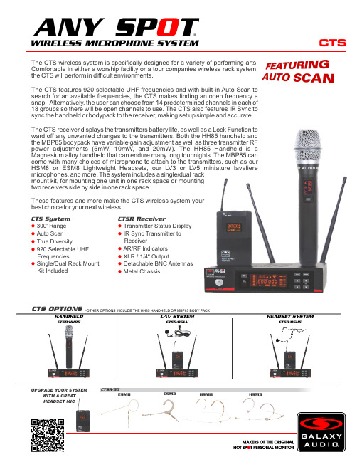
CTSThe CTS wireless system is specifically designed for a variety of performing arts. Comfortable in either a worship facility or a tour companies wireless rack system, the CTS will perform in difficult environments.The CTS features 920 selectable UHF frequencies and with built-in Auto Scan to search for an available frequencies, the CTS makes finding an open frequency a snap. Alternatively, the user can choose from 14 predetermined channels in each of 18 groups so there will be open channels to use. The CTS also features IR Sync to sync the handheld or bodypack to the receiver, making set up simple and accurate.The CTS receiver displays the transmitters battery life, as well as a Lock Function to ward off any unwanted changes to the transmitters. Both the HH85 handheld and the MBP85 bodypack have variable gain adjustment as well as three transmitter RF power adjustments (5mW, 10mW, and 20mW). The HH85 Handheld is a Magnesium alloy handheld that can endure many long tour nights. The MBP85 can come with many choices of microphone to attach to the transmitters, such as our HSM8 or ESM8 Lightweight Headsets, our LV3 or LV5 miniature lavaliere microphones, and more. The system includes a single/dual rack mount kit, for mounting one unit in one rack space or mounting two receivers side by side in one rack space.These features and more make the CTS wireless system your best choice for your next wireless.CTSR/85ESM8HSM3HSM8ESM3CTS OPTIONS-OTHER OPTIONS INCLUDE THE HH85 HANDHELD OR MBP85 BODY PACKI RS Y NCCTS System 300Range ●' Auto Scan ● True Diversity● 920 Selectable UHF ● FrequenciesSingle/Dual Rack Mount ● Kit IncludedCTSR ReceiverTransmitter Status Display ● IR Sync Transmitter to ● ReceiverAR/RF Indicators ● XLR / 1/4 Output●" Detachable BNC Antennas ● Metal Chassis●LAV SYSTEMCTSR/85LVHEADSET SYSTEMCTSR/85HSHANDHELDCTSR/HH85WIRELESS MICROPHONE SYSTEM®ANY SP TO UPGRADE YOUR SYSTEMWITH A GREAT HEADSET MICSpecifications subject to change without notice.V20190422601 E. Pawnee Wichita, KS 67211 316. 263.2852 FAX 316.263.0642 Distributed in Canada by Audio Distributors International (ADI ) 1275 Newton, unit 6 Boucherville, QC J4B 5H2 Canada450.449.8177 FAX 450.449.8180CTSSpecifications:CTS SystemAvailable Frequencies: 920Transmitter Output Level: 5 mW, 10 mW, 20 mW Band: UHF FrequencyOperating Range: Under Typical Conditions 300' (92 m), actual range depends on RF signal absorption, reflection, and inference. Audio Frequency Response: (+/-3dB) 60Hz - 16KHzTotal Harmonic Distortion: (+/-30kHz deviation, 1kHz tone): <1%Dynamic Range: >90dB A-weightedOperating Temperature Range: 14°F to 122°F (-10°C to +50°C),battery characteristics may limit this rangeIncluded Accessories: Single/Dual Rack Kit, Antenna Plugs x2,Power Supply, Antennas x2, 1/4" to 1/4" Audio Cable x1, Quick Start Guide Receiver (CTSR)Audio Output Level (+/-30kHz deviation, 1kHz tone): XLRConnector (into 600 Ohm load), 1/4" Connector (into 3k Ohm load)Output Connections: 1 Male XLR Balanced, 1/4" UnbalancedOutput Impedance: XLR connector 200 Ohms, 1/4" connector 1k Ohms XLR Output: Impedance balanced Pin 1: Ground (cable shield)Pin 2: Audio +Pin 3: No Audio -Sensitivity: -102dBm Image Rejection: >90dBCasing: Metal Chassis EIA STANDARD 1/2 UDimensions: 1.7" x 8.3" x 6.3" (45 x 212 x 160mm) (HxWxD)Weight: 31.7 oz (900 g)Power Requirements: 12Vdc at 500 mA,supplied by external power supplyDynamic Cardioid Handheld Transmitter (HH85)Max Audio Input Level: -4.44dBv (-3 gain)Gain Adjust: software control -3dB to +9dB in 3dB steps RF Output: 5 mW, 10 mW, 20 mW Frequency Response: 60Hz - 15kHzDimensions: 9.68" x 2.08" (246 x 53mm)(LxDia.)Weight: 8.8 oz (250 g) (without batteries)Power Requirements: 2 “AA” Batteries, alkaline or rechargeable Battery Life: About 12 hours (alkaline)Body Pack Transmitter (MBP85)Max Audio Input Level: -6dBV (-3 gain)Gain Adjust: -3dB, 0dB, +3dB, +6dB, +9dB RF Output: 5 mW, 10 mW, 20 mW Input Impedance: 470k OhmsDimensions: 2.51" x 3.85" x 0.90" (64 x 98 x 23 mm)(HxWxD)Weight: 3.17 oz (90 g) (without batteries)Power Requirements: 2 “AA” Batteries, alkaline or rechargeable Battery Life: About 12 hours (alkaline)WIRELESS MICROPHONE SYSTEM®ANY SP TO CTSR ReceiverBACK VIEWTOP VIEWMBP85HH85。
森海塞尔 XS Wireless 1 DUAL 2 通道无线系统 说明书

1/3FEATURES–Excellent live sound featuring Sennheiser's renowned evolution microphone capsules–Antenna-switching 2-channel diversity reception –Integrated antennas–Automatic frequency management and synchronization via remote channel for easy setup–Selectable UHF frequencies within a large bandwidth –Up to 10 compatible channelsDELIVERY INCLUDES–2x SKM 825-XSW or SKM 835-XSW handheld trans-mitters with mute switch and e825 cardioid dynamic capsules–2x MZQ 1 microphone clips–EM-XSW 1 DUAL stationary 2-channel receiver with internal antennas–NT 12-5 CW power supply –2x AA batteries –Quick guideXS WIRELESS 1 DUAL2-channel wireless system for singers and presenters.SPECSHEET DESCRIPTIONRaise your voice. XS Wireless 1 DUAL is a 2-channel wireless system for singers and presenters. Designed with ease of use in mind, these analog UHF systems feature a sleek dual-channel receiver with built-in antennas and the streamlined interface from Sennhei-ser's popular XS Wireless 1 series..FREQUENCY RANGES A-Range:548-572 MHzLOGISTICS INFORMATION ModelSingle itemMaster cartonXSW 1-825 DUAL weight: 2110g/1.4 lbs weight: 7360g/16.2 lbs, packs of 3XSW 1-835 DUAL weight: 2110g/1.4 lbs weight: 7360g/16.2 lbs, packs of 3EM-XSW 1 DUALweight: 1384g/3.1 lbsweight: 5182g/11.4 lbs, packs of 3TECHNICAL DATASystemModulation Wideband FMSwitching bandwidth Up to 24 MHzFrequencies 80 factory presets(8 banks of 10 channels each) Signal-to-noise ratio ≥ 103 dBATHD≤0.9%Temperature range Operation: 0°C to +40°CStorage: –20°C to +70°C Transmitter synchronization 2.4 GHz, low power OQPSK(only active during synchronization) Dimensions Ø 48 x L 180 mmWeight 330 g (0.73 lbs)Transducer principle dynamicFrequency response 55 - 16,000 HzPick-up pattern cardioidSensitivity 1.8 mV/Pa (free field, no load at 1 kHz) Nominal impedance 300 Ω (at 1 kHz)Min. terminating impedance 1 kΩConnector XLR-3Temperature range 0 °C ... +40 °C (+32 °F ... +104 °F)EM-XSW 1 DUALReceiver principle Double superheterodyneDiversity principle A Antenna switching diversity via internal antennasSensitivity (at peak deviation) < 3 μV at 52 dB(A) rms S/NAF frequency response 50 to 16,000 Hz (–3 dB)Max. AF output voltage (at peak deviation, 1 kHz AF) 1/4“(6.3 mm) socket (unbalanced):+6dBuXLR socket (balanced): +12 dBuAudio adjustment range 45 dB, adjustable in 5 dB stepsPower supply 12 V DC nom. / 300 mASquelch Adjustable from 3 dBμV to 28 dBμV Line/Mic level 20 dB, switchableHousing material Rugged ABS housingDimensions (W x H x D) approx. 320 x 126.5 x 42 mmWeight approx. 620 gSKM 825-XSW and SKM 835-XSWRF output power 10 mWAF frequency response 80-16,000 HzPower supply 2 AA size batteries, 1.5 VOperating time Approx. 10 hrsMicrophone type DynamicPick-up pattern CardioidInput sensitivity (capsule) 1.5 mV / PaTransmitter sensitivity 0 to -30 dB, adjustable in 10 dB steps Housing material Rugged ABS housingDimensions (L x Ø) Approx. 260 x 50 mmWeightApprox. 245 gcontinued on page 3VARIANTSEANUPCNo.i clei antVarArtXSW 1-825 DUAL XSW 1-825 DUAL-A 508263 4044155238242 6151043154716151043154884044155238259 XSWDUAL-B 5082641-8254044155238266615104315495DUAL-C 5082651-825XSW615104315501DUAL-D 5082664044155238273 XSW1-8254044155238280DUAL-E 5082676151043155181-825XSW4044155238297615104315525DUAL-GB 5082681-825XSW6151043155324044155238303 XSW1-825DUAL-K 508269XSW 1-825 DUAL XSW 1-835 DUAL-A 508270 4044155238310 61510431554940441552383276151043155561-835DUAL-B 508271XSW4044155238334DUAL-C 5082726151043155631-835XSW4044155238341DUAL-D 5082736151043155701-835XSW4044155238358615104315587DUAL-E 5082741-835XSW6151043155944044155238365 XSWDUAL-GB 5082751-8354044155238372615104315600DUAL-K 508276XSW1-835EM-XSW 1 DUAL EM-XSW 1 DUAL-A 508277 4044155238389 615104315617DUAL-B 50827861510431562440441552383961EM-XSW4044155238402DUAL-C 5082796151043156311EM-XSW4044155238419615104315648DUAL-D 5082801EM-XSW40441552384266151043156551DUAL-E 508281EM-XSWDUAL-GB 50828261510431566240441552384331EM-XSW40441552384406151043156791EM-XSWDUAL-K 508283。
FIBOCOM_G510 硬件用户手册_V1.0.0_H

注意
由于产品版本升级或其他原因,本文档内容会不定期进行更新。除非另有约定,本文档仅作为使用指导, 本文档中的所有陈述、信息和建议不构成任何明示或暗示的担保。
商标申明
为深圳市广和通无线股份有限公司的注册商标,由所有人拥有。
版本记录
文档版本 V1.0.0_H 更新日期 2016-03-04 说明 初始版本
本文件版权属深圳市广和通无线股份有限公司所有,未经批准,不得复制。 G510 硬件用户手册 Page 3 of 35
目录
1 前言...........................................................................................................................................6
3.4 开关机......................................................................................................................................... 14
3.4.1 模块开机................................................................................................................................... 14 3.4.2 模块关机................................................................................................................................... 15
动V+无线中文说明书

致动V+无线中文说明书目录一、键位二、模式与模式灯三、PC电脑连接四、任天堂Switch连接五、安卓设备蓝牙连接六、关机和自动休眠七、低电量提示八、充电九、功能复位与强制断电十、按键连发十一、扳机线性开关十二、十字键与左摇杆功能互换十三、震动开关十四、摇杆精度调节十五、ABXY键位切换基础功能额外功能(以下功能非必须使用,用不到可以忽略)------------------------------------------------------------2---------------------------------------------------3----------------------------------------------------4----------------------------------------------7---------------------------------------------10-----------------------------------------------12----------------------------------------------------12-----------------------------------------------------------13------------------------------------------13------------------------------------------------------14-----------------------------------------------15-----------------------------------16----------------------------------------------------16-----------------------------------------------17----------------------------------------------18ZD-V+Wireless Controller Chinese Manual一、键位十字键右摇杆左摇杆*后续使用说明所用到的按键都以蓝色PC键位为参考。
石家庄陆杰电子科技有限公司 Wi-Fi通信模块使用说明说明书
Wi-Fi通信模块使用说明石家庄陆杰电子科技有限公司版本:20230309V1.1基本说明感谢您购买了陆杰Wi-Fi通信模块(WiFi-UART)。
本手册主要介绍Wi-Fi通信模块(WiFi-UART)使用内容。
在使用产品之前,请仔细阅读本手册,并在充分理解手册内容的前提下,进行使用软件及硬件方面的介绍,请查阅相关手册。
用户须知手册等其他技术资料中所列举的示例仅供用户理解、参考用,不保证一定动作。
将该产品与其他产品组合使用的时候,请确认是否符合有关规格、原则等。
使用该产品时,请自行确认是否符合要求以及安全,对于本产品故障而可能引发机器故障或损失时,请自行设置后备及安全功能。
责任申明手册中的内容虽然已经过仔细的核对,但差错难免,我们不能保证完全一致。
我们会经常检查手册中的内容,并在后续版本中进行更正,欢迎提出宝贵意见。
手册中所介绍的内容,如有变动,请谅解不另行通知。
联系方式如果您有任何关于本产品的使用问题,请与购买产品的代理商、办事处联系,也可以直接与陆杰公司联系。
电话:400-657-7769*************地址:石家庄栾城区邵家庄工业路2号邮编:050000网址:/未经明确的书面许可,不得复制、传翻或使用本资料及其中的内容,违者要对造成的损失承担责任。
保留包括实用模块或设计的专利许可及注册中提供的所有权力。
二零二二年六月目录一、基本说明 (4)二、硬件设备说明 (4)三、连接方式说明 (5)四、配置软件说明 (5)五、操作说明 (6)六、微信小程序使用说明 (7)七、故障排除 (10)一、基本说明Wi-Fi通信模块(Wi-Fi-UART)(以下简称模块)具备USB转232、转485、转422、串口转Wi-Fi的功能,适用PLC、HMI等串口设备的读写监控,数据传输功能。
1)通过WiFi-UART配置软件PC端或微信小程序,可以配置模块接入互联网,实现远程数据透传。
2)通过USB接口,插入电脑,可以实现USB转232(485,422)功能。
SVX无线系统用户指南说明书

SVX Wireless SystemOnline user guide for SVX wireless system. Version: 1.0 (2022-A)Table of ContentsSVX Wireless System3安全事項3快速設定3 Shure SVX 無線系統4接收機4發射機 5系統組件6所有系統 6手持式發射機 6腰包式發射機 6電源6連接到音響系統 7頻道 7腰包增益 7 RF 水平 7靜噪 7電池電量過低指示燈 7顏色標識環 7獲得良好音質7正確放置麥克風 8佩戴頭戴式麥克風 8腰包式傳送器的佩戴 8可提高系統性能的無線使用提示9故障排除9選配附件10備件10 10頻率範圍10澳大利亞無線警告11規格 11SVXWireless System安全事項根據危險程度和損壞嚴重性的不同,使用“警告”和“小心”文字對未正確使用可能導致的後果做出標識。
警告:如果沒有遵循這些警告事項,在操作不正確的情況下可能會導致嚴重的人身傷亡事故。
小心:如果沒有遵循這些警告事項,在操作不正確的情況下可能會導致常見的人身傷害或財產損失。
警告如果有水或其他異物進入設備內部,可能會導致起火或觸電事故。
不要嘗試改裝本產品。
這樣做會導致人身傷害和/或產品故障。
小心不要拆開或改裝本設備,這樣可能會導致故障。
不要用力過大,不要拉扯線纜,否則會損壞線纜。
讓話筒保持乾燥,並避免暴露在極高溫度和濕度環境下。
快速設定Shure SVX 無線系統恭喜您購買了舒爾的 SVX 無線系統。
舒爾專業音響產品能夠提供出色的音響質量,在舞臺上經久耐用,讓您的演出輕鬆自如。
SVX 無線系統可與領夾式、手持式或頭戴式話筒一起使用,適用於演示、卡拉 OK 表演、增氧運動/健身教練或其它需要無線移動功能場合。
接收機KCX4KCX88①電源指示燈②音訊指示燈③無線電頻率密度指示燈④平衡輸出(XLR 接頭)⑤非平衡輸出(6.35 毫米接頭)⑥音訊輸出電平(線路/話筒)切換製⑦頻道選擇旋鈕⑧靜噪旋鈕⑨電源適配器輸入⑩天線發射機①電源按鈕••••••••••② 頻道選擇旋鈕③ 音訊輸入電平(線路/話筒)切換開關④ 電池艙⑤ 發射機增益旋鈕⑥ 皮帶夾⑦ 話筒輸入(CVL 領夾式或 PGA31 頭戴式)⑧ 無線電射頻 (RF) 電平切換開關⑨ 天線⑩ 顏色標識環⑪ 防滾環⑫ 電源 LED 指示燈系統組件所有系統SVX 接收機PS24 電源部件頻道選擇工具2 枚 AA 電池手持式發射機SVX2 手持式話筒發射機話筒底座轉接頭腰包式發射機SVX1 腰包式發射機話筒PG185 領夾式話筒或PG30 頭戴式話筒電源插上電源適配器,將接收機電源打開。
中控主机说明书2015(中性)
可编程智能中央控制系统PROGRAMMABLE CENTER CONTROL SYSTEM用户手册在使用前,请仔细阅读本用户手册目录一、可编程中控系统概述 ............................................................................................................ - 5 -1.1WIFI中控主机简介............................................................................................................... - 5 -1.1.1 系统概述........................................................................................................................... - 5 -1.1.2功能特性............................................................................................................................ - 5 -1.1.3 控制端口........................................................................................................................... - 6 -1.1.4 主要技术参数................................................................................................................... - 6 -1.1.5 规格................................................................................................................................... - 6 -1.2可编程中控主机简介........................................................................................................... - 6 -1.2.1 系统概述........................................................................................................................... - 6 -1.2.2功能特性............................................................................................................................ - 7 -1.2.3 控制端口........................................................................................................................... - 7 -1.2.4 主要技术参数................................................................................................................... - 8 -1.2.5 规格................................................................................................................................... - 8 -1.3带矩阵中控-I主机简介 (8)1.3.1 系统概述........................................................................................................................... - 8 -1.3.2 功能特性........................................................................................................................... - 8 -1.3.3 控制端口........................................................................................................................... - 9 -1.3.4 主机技术参数................................................................................................................... - 9 -1.3.5规格.................................................................................................................................... - 9 -1.4带矩阵中控-II主机简介.. (9)1.4.1系统概述............................................................................................................................ - 9 -1.4.2功能特性.......................................................................................................................... - 10 -1.4.3 控制端口......................................................................................................................... - 10 -1.4.4 主要技术参数................................................................................................................. - 10 -1.4.5 规格.................................................................................................................................. - 11 -二、系统结构体系 ...................................................................................................................... - 11 -2.1WIFI中控主机系统结构体系 (11)2.1.1 前面板说明...................................................................................................................... - 11 -2.1.2 后面板说明...................................................................................................................... - 11 -2.2可编程中控主机系统结构体系 (13)2.2.1 前面板说明..................................................................................................................... - 13 -2.2.2 后面板说明..................................................................................................................... - 13 -2.3带矩阵中控-I系统结构体系 (14)2.3.1 前面板说明..................................................................................................................... - 16 -2.3.2 后面板说明..................................................................................................................... - 16 -2.4带矩阵中控-II系统结构体系 (17)2.4.1 前面板说明..................................................................................................................... - 17 -2.4.2 后面板说明..................................................................................................................... - 18 -三、安装连接详解 ...................................................................................................................... - 19 -3.1WIFI中控主机安装连接说明 (19)3.1.1 串行控制口连接详解..................................................................................................... - 19 -3.1.2 红外发射口连接详解..................................................................................................... - 20 -3.1.3 NET口连接详解 ............................................................................................................. - 20 -3.1.4 弱电继电器口连接详解................................................................................................. - 21 -3.1.5 用户程序下载口连接详解............................................................................................. - 22 -3.1.6无线路由连接详解.......................................................................................................... - 22 -3.3可编程中控主机安装连接说明 (23)3.3.1 串行控制口连接详解..................................................................................................... - 23 -3.3.2 红外发射口连接详解..................................................................................................... - 25 -3.3.3 NET口连接详解 ............................................................................................................. - 25 -3.3.4 弱电继电器口连接详解................................................................................................. - 26 -3.3.5 用户程序下载口连接详解............................................................................................. - 27 -3.4带矩阵中控-I安装连接说明.. (28)3.4.1 串口控制口连接详解..................................................................................................... - 28 -3.4.2 红外发射/ IO口连接详解............................................................................................ - 28 -3.4.3 CRV-NET口连接详解..................................................................................................... - 29 -3.4.4 程序下载口连接详解..................................................................................................... - 30 -3.5带矩阵中控-II安装连接说明 (30)3.5.1 串行控制口连接详解..................................................................................................... - 30 -3.5.2 红外发射/IO口/可编程串口3连接详解...................................................................... - 30 -3.5.3 NET口连接详解 ............................................................................................................. - 31 -3.5.4 程序下载口连接详解..................................................................................................... - 32 -四、软件编程 .............................................................................................................................. - 32 -4.1编译、下载程序 (32)4.2红外学习 (35)4.3红外码的导入、编译、下载 (39)五、典型应用连接图 .................................................................................................................. - 42 -5.1WIFI中控主机典型应用连接图 (42)5.2可编程中控主机典型应用连接图 (43)5.3带矩阵中控-II典型应用连接图 (44)六、常见问题及解决办法 .......................................................................................................... - 44 -一、可编程中控系统概述1.1 WIFI中控主机简介1.1.1 系统概述WIFI中控主机是基于iOS平台手持终端(ipad/iphone、Android)的网络中控主机,它支持网络级联,实现智能控制网络化,并且全面兼容传统中控编程控制方式,拥有豪华亮丽的外观,她的面世,必将是新一代智能中控主机代表,引领中控领域的发展潮流。
Shure ULX无线系统产品说明书
Shure ULX WirelessULX sans fil de Shure Sistema inalámbrico ULX de Shure Sistema ULX Sem Fio da Shure©2011 Shure Incorporated27A15788 (Rev. 1)2Shure ULX WirelessULX System Components31 x UA506 1 x UA6002 x UA8201 x UA440 1 x UA507 4 x UA8201 x UA844 1 x UA507 4 x UA5061 x UA8442 x UA507Rack InstallationRackmount OptionsThe following shows rackmounting options for one to four receivers andlists the required accessories.FRONT MOUNT ANTENNA KITUA600COAXIAL CABLESUA802UA806UA825UA850UA100UA830UA870FOR LONG ANTENNA CABLE RUNSUA870UA844DISTRIBUTION AMPLIFIERANTENNA RACK MOUNT KITUA440Antenna Combiners and AccessoriesThe supplied antennas can be connected directly to the BNC-type ANTENNA connectors. However, optional antenna mounting accessories from Shure can improve reception and reduce rack clutter. Use the following guidelines:• Antennas and receivers must be from the same band.• Mount antennas more than 40 cm (16 inches) apart.• Use Shure UA825 or UA850 low-loss coaxial antenna cable (or any 50 ohm, low-loss cable such as RG-8U).Visit for more information on wireless antenna accessories.UA600Coaxial CablesInline Antenna Amplifier for long antenna cable runsAntenna Rack Mount Kit Distribution Amplifier combines antennas and power supplies formultiple receivers Active Directional Antennafor more focused receptionFront Mount Antenna Kit UA802 UA806 UA825 UA850 UA100UA830UA440UA8444Power ConnectorConnect using the supplied AC adapter or certi-fied 14–18 Vdc (550 mA) replacement supply.BatteriesPower/Mute Switch• Turn transmitter off to mute the microphone or conserve battery power.• Use the lock feature to avoid accidental muting of the microphone during a performance.Power Indicator (BAT)Green: readyRed: battery power lowNOTE: Remaining battery life varies with battery type.Both the transmitter and receiver LCD shows approximate operation time remaining for the transmitter.Battery LifeUse only 9V alkaline or lithium batteries. Typical life for common types of 9V batteries are listed below. For detailed information on battery perfor-mance, contact Shure Applications Engineering. Recommended:• Lithium (16 hours)• Alkaline (8 hours)Not recommended:• Carbon-Zinc (½ hour)• Rechargeable Ni-Cd (2 hours)• Rechargeable Ni-MH (2½ hours)NOTE:• Battery life varies with type and manufacturer.• Batteries stored for more than a year or stored in excessively hot environments may experience a higher failure rate.• Do not use rechargeable batteries with a fully-charged rating of greater than 9 V (for example, 9.6 V).• Transmitters require a minimum of 6 V to operate.12Automatic Frequency ScanChannel ScanThis feature scans for an open channel in the selected group.Group Scan (ULXP4 only)The “group scan” feature on the ULXP helps maximize the number ofsystems you can install at a single venue. It scans for wireless interfer-ence and finds the group with the most open channels.Changing Group and ChannelIf you encounter wireless interference, set the receiver and transmitter toa different channel or group.Note: You can reverse the scroll direction by holding SET andpressing MODE.Frequency Master List ModeMaster List mode offers more precise frequency selection for larger,multiple-system installations.Enter Master List mode on the receiver or transmitter by holding down theSET button for 10 seconds. Set GROUP and CHANNEL as you would innormal mode.NOTE: The unit must remain in Master List mode to operate at the se-lected frequency.Exit Master List mode by holding the SET button for 10 seconds.Single SystemIf you encounter wireless interference, perform a channel scan on the re-ceiver and use the selected channel. You usually do not need to changethe group.Multiple SystemsTo maximize performance, set all wireless systems to different channelsfrom the same group. These channels are selected to work well together.Follow these steps when using group and channel scan with multiplesystems.1. Power off all system transmitters. Turn on all other wireless or digitaldevices as they would be during the performance or presentation.2. On the first receiver: Perform a group scan. Note the selected group,then use channel scan to find the first open channel in that group.3. Power on the first transmitter and set it to the selected group andchannel.4. IMPORTANT: Leave the first transmitter powered on while setting upthe next system.5. For each additional system: Set to the same group as the first.Perform a channel scan and set the receiver and transmitter to theselected channel.6. Leave each transmitter on while setting up additional systems.Note:• Keep each transmitter at least two meters (6 feet) apart.• If using systems from different bands, set up all systems from the sameband together.Tip: To reduce setup time, you can manually set up the group and chan-nels before arriving at the venue. Visit for a list of groupsand channels that are anticipated to be free of interference in a particularcity or region.5Wireless IndicatorsRF IndicatorIndicates wireless activity over the selectedchannel.Note: When the antenna and battery indica-tors are illuminated, the RF indicator showssignal strength from the transmitter. Otherwise,it is showing interference from another source.Select a different channel.Antenna IndicatorThis indicator shows which an-tenna is receiving the strongestsignal from the transmitter.For models sold in the United States only.Displays the TV channel occupied by theselected frequency.Frequency DisplaySquelchThe factory setting offers the optimum performance for most installations.Increasing squelch filters out all but the highest quality signal, but this decreases operating range. Decreasing squelchextends the operating range, but can increase signal noise.Audio OutputAudio Output ConnectorsBalanced XLR: Connect to a mixer or other professionalaudio input. Use the MIC/LINE switch to adjust for micro-phone or line-level inputs.Unbalanced 6.35 mm (1/4”): Connect to high impedanceinputs, such as a guitar amplifier.NOTE: The LINE/MIC switch does not affect the 6.35 mm(1/4”) jack.Receiver Output LevelAdjusts the level of the receiver’s audio outputs.67Transmitter GainFor best audio quality, adjust transmitter gain so only the green and yel-low TX AUDIO LEDs flicker. (Occasional illumination of the red LED is okay.)Green=nominal Yellow=peak Red=overloadULX11. Set the attenuator (pad) switch to 0 dB for microphones and –20 dB for guitars. (Some low output instruments may not need attenuation.)2. Adjust gain control as necessary.ULX2• Fully clockwise for quiet to normal vocal performance.• Halfway counterclockwise for loud vocal performance.• Fully counterclockwise for horn or percussive instruments.Audio Input MeterPEAK IconThis icon appears when the input signaloverloads the transmitter. The icon is dis-played for 2 seconds after input overload is detected.Locking the Receiver (ULXP4 Only)This feature prevents accidental setting changes.UnlockingHold the SET button while turning the control wheel left, right, left.Locking the TransmitterLock FrequencyLock Power (On)84-PIN MINI CONNECTORTA4FTIP SLEEVEINSTRUMENT CABLECONDENSER MICROPHONE BODYPACK TRANSMITTERTroubleshootingNo power: Check battery and power supply connections and voltage. Check the power switch on the transmitter.The LCD displays “E0 00” or similar code: Exit master list mode by holding the SET button for ten seconds.Can’t turn off or change settings on the transmitter or receiver: The interface is locked. See the section on locking the interface.No audio: If the antenna and battery indicators do not appear on the re-ceiver, then it is not receiving a signal from the transmitter. Make sure the transmitter and receiver are tuned to the same group and channel.Faint or distorted audio: Adjust transmitter gain, bodypack attenuator switch, and receiver output level.Noise: Noise usually results from wireless interference or a weak signal from the transmitter. See Tips for Improving System Performance .Tips for Improving System PerformanceIf you encounter wireless interference or drop outs, try the following:• Replace the transmitter battery with a fresh alkaline battery (avoid rechargeable batteries).• Choose a different frequency channel.• Reposition the antennas so there is nothing obstructing a line of sight to the transmitter (including the audience). • Avoid placing transmitter and receiver where metal or other dense materials may be present.• Move the receiver to the top of the equipment rack (or remote mount antennas outside the rack).• Remove nearby sources of wireless interference, such as cellphones, two-way radios, computers, media players, and digital signal processors. • Keep transmitters more then two meters (6 feet) apart.• Keep the transmitter and receiver more than 5 meters (15 ft) apart.• Point the receiver antenna tips away from each other at a 45° angle, and keep them away from large metal objects. • During sound check, mark “trouble spots” and ask presenters or performers to avoid those areas.9ULXS4, ULXP4ULX2ULX1SPECIFICATIONSULX1, ULX2, ULXS4, ULXP4This Class B digital apparatus complies with Canadian ICES-003.Cet appareil numérique de la classe B est conforme à la norme NMB-003 du Canada.Meets requirements of EMC standards EN 300 422 Parts 1 and 2 and EN 301 489 Parts 1 and 9.Meets essential requirements of European R&TTE Directive 99/5/EC, eligible to bear the CE mark.ULX1, ULX2Certified under FCC Part 74. (FCC ID: DD4ULX1, DD4ULX2,DD4ULX1G3, DD4ULX2G3). Certified by IC in Canada under RSS-123 and RSS-102. (IC: 616A-ULX1, 616A-ULX2).ULXS4, ULXP4Approved under the Declaration of Conformity (DoC) provision of FCC Part 15. Certified in Canada by IC to RSS-123. (IC: 616A-ULX4). Conforms to European Regulation (EC) No. 1275/2008, as amended. Operation of this device is subject to the following two conditions: (1) this device may not cause interference, and (2) this device must accept any interference, including interference that may cause undesired operation of the device.The CE Declaration of Conformity can be obtained from Shure Incorporated or any of its European representatives. For contact informa-tion please visit The CE Declaration of Conformity can be obtained from: / europe/complianceAuthorized European representative:Shure Europe GmbHHeadquarters Europe, Middle East & AfricaDepartment: EMEA ApprovalWannenacker Str. 28D-74078 Heilbronn, GermanyPhone: +49 7131 72 14 0Fax: +49 7131 72 14 14Email:********************LICENSING INFORMATIONLicensing: A ministerial license to operate this equipment may be re-quired in certain areas. Consult your national authority for possible requirements. Changes or modifications not expressly approved by Shure Incorporated could void your authority to operate the equipment. Licensing of Shure wireless microphone equipment is the user’s respon-sibility, and licensability depends on the user’s classification and applica-tion, and on the selected frequency. Shure strongly urges the user to contact the appropriate telecommunications authority concerning proper licensing, and before choosing and ordering frequencies.Information to the userThis equipment has been tested and found to comply with the limits for a Class B digital device, pursuant to Part 15 of the FCC Rules. These limits are designed to provide reasonable protection against harmful interference in a residential installation. This equipment generates uses and can radiate radio frequency energy and, if not installed and used in accordance with the instructions, may cause harmful interference to radio communications. However, there is no guarantee that interference will not occur in a particular installation. If this equipment does cause harmful interference to radio or television reception, which can be determined by turning the equipment off and on, the user is encouraged to try to correct the interference by one or more of the following measures:• Reorient or relocate the receiving antenna.• Increase the separation between the equipment and the receiver.• Connect the equipment to an outlet on a circuit different from that to which the receiver is connected.• Consult the dealer or an experienced radio/TV technician for help. Note: EMC conformance testing is based on the use of supplied and rec-ommended cable types. The use of other cable types may degrade EMC performance.Changes or modifications not expressly approved by the manufac-turer could void the user’s authority to operate the equipment.WARNING: Dispose of properly. Check with local vendor forproper disposal of used battery and electronics.CERTIFICATION10Furnished AccessoriesMicrophone Stand Adapter (ULX2)WA371Grip/Switch Cover (ULX2)WA555Zipper Bag (ULX1)95A2313Zipper Bag (ULX2)95B2313Screwdriver (ULX2)80A498 Optional AccessoriesPassive Antenna Splitter/Combiner Kit UA221UHF Line Amplifier UA830WBUHF Powered Directional Antenna UA870WB UHF Antenna Power Distribution Amplifier (U.S.A.)UA844SWBUHF Antenna Power Distribution Amplifier (Europe) UHF Antenna Power Distribution Amplifier (UK)UA844SWB-UK33 m (100 ft.) BNC–BNC cable UA81001.8 m (6 ft.) BNC–BNC cable UA806Antenna Rack Panel UA440 Front Mount Antenna Kit (Includes 2 cables and 2 bulk-head adapters)UA600 Remote Antenna Bracket with BNC Bulkhead Adapter UA505 Front Mount Antenna Kit (Includes 2 cables and 2 bulk-head adapters)UA506Rack Mount Kit for Two Receivers UA507Carrying Case WA610Microphone Adapter Cable (XLR)WA310Replacement PartsAC Adapter (120 VAC, 60 Hz)PS41AC Adapter (220 VAC, 50 Hz)PS41ARAC Adapter (230 VAC, 50/60 Hz)PS41AZ AC Adapter (230 VAC, 50/60 Hz, Europlug)PS41EAC Adapter (230 VAC, 50/60 Hz)PS41UKAC Adapter (100 VAC, 50/60 Hz)PS41J SM58® Cartridge with Grille (ULX2/58)RPW112 BETA 58A® Cartridge with Grille (ULX2/ BETA 58)RPW118 SM86 Cartridge with Grille (ULX2/SM86)RPW114SM87A Cartridge with Grille (ULX2/87)RPW116 BETA 87A Cartridge with Grille (ULX2/BETA 87A)RPW120 BETA 87C Cartridge with Grille (ULX2/BETA 87C TM)RPW122Matte Silver Grille for SM58®RK143GMatte Silver Grille for SM86RPM226Matte Silver Grille for BETA 58A®RK265GMatte Silver Grille for BETA 87A RK312Black Grille for SM87A RK214GBlack Grille for BETA 58A RPM323G Black Grille for BETA 87A and BETA 87C RPM324GBelt Clip44A8013A1/4-Wave Antenna (470 - 752 MHz)UA400B1/4-Wave Antenna (774 - 952 MHz)UA4001/2-Wave Antenna (774 - 862 MHz)UA820A1/2-Wave Antenna (638 - 698 MHz)UA820L31/2-Wave Antenna (554 - 590 MHz)UA820D1/2-Wave Antenna (740 - 814 MHz)UA820Q1/2-Wave Antenna (470 - 530 MHz)UA820G1/2-Wave Antenna (746 - 784 MHz)UA820E1/2-Wave Antenna (572 - 596 MHz)UA820F1/2-Wave Antenna (578 - 638 MHz)UA820JAccessories and Parts11ULX FREQUENCIES FOR EUROPEAN COUNTRIESULX SYSTEM COMPATIBILITY GUIDE FOR FREQUENCY BAND X3 (925-932 MHz) ©2011 Shure Incorporated Asia, Pacific:Shure Asia Limited 22/F , 625 King’s Road North Point, Island East Hong Kong Phone: 852-2893-4290Fax: 852-2893-4055Email:**************.hk United States, Canada, Latin America, Caribbean:Shure Incorporated 5800 West Touhy Avenue Niles, IL 60714-4608 USA Phone: 847-600-2000Fax: 847-600-1212 (USA)Fax: 847-600-6446Email:**************Europe, Middle East, Africa:Shure Europe GmbH Jakob-Dieffenbacher-Str. 12,75031 Eppingen, Germany Phone: 49-7262-92490Fax: 49-7262-9249114Email:*************。
无线开关系统用户指南说明书

256 AVAILABLE CODES ON EACH SWITCHYou can select any one of 256 codes on Switch “A” and also any one of 256 codes on switch “B”NOTE:The manufacturer strongly recommends that you test your equipment frequently. From the time of installation, it is absolutely necessary to test the system at least once a week. It is also good practice to change the 9-volt battery every six months.NOTE:The transmitter transmits continuously with button depression. An LED lights during transmission to indicate battery operation.LIMITED WARRANTYThis product is warranted to the consumer against defects inmaterial and workmanship for one year from the date of purchase.This warranty applies to first retail buyers of new devices. Warrantorwill repair, or at its option, replace, any device it finds that requiresservice under this warranty, and will return the repaired or replaceddevice to the consumer at the warrantor’s cost. For warranty serviceand shipping instructions contact warrantor at the address shownbelow. Devices must be sent to warrantor for service at owner’sexpense. The remedies provided by this warranty are exclusive.Implied warranties under state law are to the one year period of thiswritten warranty. Some states do not allow limitations on how longan implied warranty lasts, so the above limitation may not apply toyou. In order to be protected by this warranty, save your proof ofpurchase and send copy with equipment should repair be required.This warranty gives you specific legal rights, and you may also haveother rights which vary from state to state.All products returned for warranty service require a ReturnProduct Authorization Number (RPM). Contact Linear TechnicalServices at 1-800-421-1587 for an RPA# and other importantdetails.IMPORTANTLinear radio controls provide a reliable communications link and fillan important need in portable wireless signaling. However, thereare some limitations which must be observed.*For U.S. installations only: The radios are required to complywith FCC Rules and Regulations as Part 15 devices. As such,they have limited transmitter power and therefore limitedrange.* A receiver cannot respond to more than one transmitted signalat a time and may be blocked by radio signals that occur onor near their operating frequencies, regardless of code set-tings.*Changes or modifications to the device may void FCC compli-ance.*Infrequently used radio links should be tested regularly toprotect against undetected interference or fault.* A general knowledge of radio and its vagaries should begained prior to acting as a wholesale distributor or dealer, andthese facts should be communicated to the ultimate users.Copyright © 1999 Linear Corporation207403 GDelta-3 SeriesDT-2ATwo-button DigitalTransmitterCode Setting Instructions(800) 421-1587 • Left Button "A" Right Button "B" BatteryTest LightDT-2A TWO-BUTTON TRANSMITTER CODE SETTINGThere are two digital coding switches in the DT-2A transmitter. Code Switch “A” is exposed by removing the battery access cover. It is the coding switch for the left button on the front of the transmitter (Button “A”).Code Switch “B” is the coding switch for the right button on the front of the transmitter (Button “B”). The switch is located behind the back cover of the transmitter. To access Coding Switch “B”, it is necessary to remove the screw located in the middle of the back cover.SETTING CODE SWITCH “A”Before removing the battery access door,loosen battery clip screw and rotate clip away from door. To open the battery access cover and gain access to Coding Switch “A”, lift off the small L-shaped cover by inserting your thumbnail or a small screwdriver under either of the two slots at the edge of the case. The coding switch has eight keys numbered 1-8.To set a code, select any combination of ON or OFF positions for the switch keys numbered 1-8. Use a paper clip or other pointed object (except a pencil or pen) to set the keys on the coding switch. The ON position is when the top of the switch is down.SETTING CODE SWITCH “B”To gain access to Coding Switch “B”, first remove the screw in the middle of the back cover. Remove the back cover to expose the 8-key switch.To set a code, select any combination of ON and OFF positions for the switch keys, in the same manner as described for Coding Switch “A”.CAUTION:It is not advisable to set a code with all keys ON, OFF, or alternating ON and OFF,because these codes are too easy to duplicate.TRANSMITTERS CODE MUST MATCH RECEIVER CODESwitch “A” is designed for use with a garage door opener. The code set to Switch “A” must be identical to the code set in the receiver to be used in conjunction with Push-button “A”Switch “B”, under the back cover is designed for use with less-frequently changed codes,such as a community gate operated by Push-button “B”. The code set into Switch “B”must be identical to the code set in the receiver to be used in conjunction with Push-button “B”.BATTERYCODING SWITCH "A"ROTATE CLIP AWAY FROM BATTERY DOOR587143O FFON6Keys 1, 2, 3, 4, and 6 OFFKeys 5, 7 and 8 ONCODING SWITCH "A"CODING SWITCH "B"REAR VIEW WITHBACK COVER REMOVED TO ACCESS SWITCH "B"。
BW无线系统操作说明书

BW 无线系统操作说明书产品特点:覆盖距离可达150米(500英尺)和定向碟形天线一起使用,则覆盖距离可达500米(1500英尺)传送多格式信号,最高达1080 /60P(3G,HD-SDI)低延时(20ms)通过音频输入端口将音频独立传输双向数据链路11Kbps时间代码传送Tally 传输,Tally LED,通过GPI接口返回Tally 传输低功耗(10W0)无需FCC许可证要求的(U-NII-1和U-NII-3)部件说明1)V板适配器用于V型电池安装的内置V板,安顿保尔适配器可连接2)V-Mount适配器V-Mount适配器用于连接V-Mount电池,替代了DV Mount,双DV Mount,或安顿保尔适配器。
3)内置电源接口DV Mount连接此接口供电4)更新接口通过迷你USB gender.接口更新固件发射器侧面板左测面板1)环路输出SDI环通输入端口2)SDI输入支持SMPTE标准音频信号的HD/ SD SDI输入端口。
3)HDMI输入端口HDMI输入端口(有音频信号),请注意,某些数码单反相机不能通过外部端口发送音频信号。
4)电源开关5)Mini USB端口用于固件更新,更新前,用户可通过我们的服务代表获取帮助。
6)直流电源输入端口12V直流电源输入接口,7~30V也可用。
右侧面板1)配对按钮当发射机和接收机配对不成功,或使用不同型号的发射机和接收机时需按下此按钮,通常用户不需要按下此按钮。
2)Link LED指示灯发射器和接收器连接上成功,此灯亮起。
3)电源指示灯4)电池指示灯电池容量低,此灯闪烁5)Tally LED指示灯当Tally 控制被使用时,此灯亮起6)SDI/HDMI选择切换选择SDI或HDMI输入7)音频输入接口此端口接收立体声音频(例如来自麦克风)、从视频端口分离出来的输入音频。
8)远程端口此端口接收tally控制信号9)红外线遥控端口遥控接收端口接收器侧面板左侧面板1) SDI 输出接口12) SDI 输出接口23) HDMI 输出接口4) 电源开关5) Mini USB 端口特殊固件更新端口6)直流电源端口12V交流电源输入接口,7~30V也可用。
GSM900M无线宽带室内主机(10mW PICO)用户手册
深圳国人通信有限公司GSM900M无线宽带室内主机(10mW/PICO)SGR-R310C-10m/PICO用户手册文件编号:SGR2.012.790SY版本:V1.0生效日期:编制:部门/职位:开发工程师日期:初审:部门/职位:项目经理日期:复审:部门/职位:部门经理日期:批准:部门/职位:总工程师日期:文件更改履历表目录1前言............................................................................................................................ .. (1)2概述........................................................................................................................ .. (1)3系统特性................................................................................................................................ ..2 4系统工作原理.. (3)5应用系统组成 (3)6系统主要技术指标 (3)7电气接口 (4)8设备安装说明 (4)8.1安装准备 (4)8.2安装流程 (5)8.3安装过程 (5)9设备调试和维护 (6)1前言随着移动通信用户数量的不断增加,而且城区、市区各种建筑物的存在,造成无线电磁波传输环境复杂等特点。
如高层楼宇、地下停车库等,基站信号无法覆盖这些地区的室内,造成这些地区出现盲区、通话质量差,给通信带来很大困难。
直放站是解决上述问题既经济又可靠的设备,本手册介绍了国人公司的最新开发产品-微功率直放站。
PowerBox 2.4 GHz 无线控制系统说明书
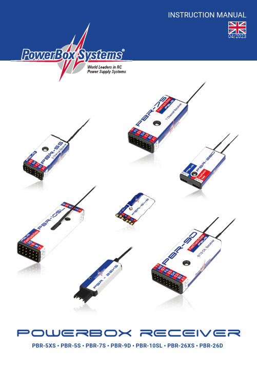
PowErBox RECEIVERPBR-5XS • PBR-5S • PBR-7S • PBR-9D • PBR-10SL • PBR-26XS • PBR-26DDear customer,We are delighted that you have decided to purchase a PowerBox transceiver, which almost certainly represents the most highly developed and most advanced transmitting and receiving system for your valuable models avai-lable anywhere in the modelling world. Unprecedented range in the 2.4 GHz band, and ultra-fast, ultra-precise data transfer in both directions - these are the outstanding features of this radio system.1. PRODUCT DESCRIPTIONIf you study the specifications closely, it is clear that PowerBox receivers are by no means “receivers” in the usual sense; they are “transceivers”. They are capable of transmitting and receiving at the same data rate and the same range as the associated system transmitter.All PowerBox transceivers feature a radio chip, but an essential difference is the integral pre-amplifier, which is one of the factors which make the system’s extremely long range possible. The PowerBox radio link is a hopping system which uses at least 66 of 198 possible channels. An intelligent hopping sequence is employed, ensuring interference-free operation even when the frequency band is heavily used.The suffix D, S/XS or SL indicates the number of radio units installed in the transceiver. The D types PBR-9D and PBR-26D incorporate two fully independent receive / transmit units.Other systems feature two aerials, switching between them 50-50, but if one aerial loses the signal, 50% of the information is inevitably lost; our design does not suffer that drawback. There are also no switching diodes which have a damping effect on the signal as it arrives; this has a particularly adverse effect on the radio chip.In contrast, both the receive units in PowerBox transceivers pick up the data packet in undamped form, and sub-ject it to a full analysis. If one of the two packets contain errors, or if the signal strength is poor, or if the signal is completely absent, the data packet picked up by the other receive unit is used, and passed to the servo outputs or digital outputs. The result is a 100% signal even if one aerial is completely blocked.As of software version 3.5 it is possible to connect a supplementary receiving unit, such as the PBR-26, to the FastTrack socket of receiver types PBR7, PBR9 and PBR10. If the primary receiver should receive no data from its integral aerials, the gap is filled seamlessly with the data from the “satellite receiver”.A further important feature is the integral iGyro system. The PBR-7S, PBR-9D, PBR-10SL and PBR-26D receivers have the iGyro software installed as standard, providing control of six separate axes. To make use of the iGyro all you have to do is connect an iGyro SAT to the FastTrack socket. If the integrated iGyro detects a GPSIII or a PBS-TAV sensor on the P²-BUS, the gyro gain is even speed-compensated!All iGyro settings can be adjusted conveniently from the transmitter using the Telemetry menu.All PBR receivers are capable of generating various BUS signals at the FastTrack socket, in order to maintain compatibility with third-part products such as helicopter gyros. In addition to S.BUS and SRXL, as of Version 3.5 an analogue PPM signal can also be available.One feature which is unique in the market is the facility to update receivers from the transmitter. You do not even need to remove the receiver or receivers from the model, or connect to the model using a laptop and USB inter-face, in order to update the receiver software.2PowerBox-Systems − World Leaders in RC Power Supply SystemsFEATURES:• 2.4 GHz transceiver matching the PowerBox radio control system• One or two receive units• Extreme interference rejection• Ultra-long range• Integrated high-performance six-axis iGyro software• iGyro system with speed-compensation• High-performance real-time telemetry transfers 800 values/second• Integral telemetry for reception quality and battery voltage• Various Bus systems for compatibility with third-party products• Receiver updates from the transmitter• Compact format2. FEATURES AND CONNECTIONSLED3. POWER SUPPLYTo ensure that PBR receivers are as compact as possible, they are not fitted with dedicated power supply sockets. The power supply should always be connected to one of the front servo outputs; use a Y-lead if none of these sockets is vacant. The data sockets of the PBR-7S and PBR-9D should not be used for the power supply, as the maximum current they can handle is 5A.3 4. BINDINGThe transceivers can be bound using either of two methods:a) Connect the transceiver firstThe LED now flashes rapidly for about ten seconds. Press “Bind” at the transmitter, and the transmitter and receiver are bound. If you do not press Bind within ten seconds, the receiver LED switches to a slower flas-hing rate. At this point the receiver can no longer be bound to the transmitter unless the power supply is first disconnected.b) Press “Bind” at the transmitter firstAfter this you connect the receiver to a power supply: the transmitter now binds with the receiver.5. DETAILED DESCRIPTION OF THE SOCKETSa) PWM outputsThe PWM outputs are sequentially numbered from 1 - XX, but are also assigned the letters A - I. As an option, you can also set the receiver outputs to generate different channel numbers. For example, the PBR-9D can be set to generate outputs 10 - 19 as well as channels 1 - 9.b) P²-BUSThis interface is used for the external ultra-fast P²-BUS telemetry system and digital servo output. When the system is switched on, all the sensors connected to this socket are scanned, and displayed at the transmitter. The P²-BUS socket can also be used for updating the receiver using the USB interface adapter.c) FastTrack / DataThis socket can be set to various functions from the transmitter: you can set it to FastTrack, P2BusOUT,S.BUS, SRXL-16, PPM12 or even one further servo output.• FastTrack:The iGyro SAT or a supplementary satellite receiver (PBR-26D or PBR-26XS) can be connected to this so-cket. FastTrack is a high-speed real-time bus system. If you wish to use both the iGyro SAT and the optional satellite receiver simultaneously, they can simply be connected using a Y-lead. Once an iGyro SAT is connec-ted, you have a six-axis iGyro system whose full range of functions can be adjusted from the transmitter.• P2BusOUT:The purpose of this option is to feed telemetry data wirelessly from the model to ground stations, as are typically used in Triangle flying events. The receiver “listens” to the radio traffic between the transmitter and the receiver in the model, and passes on the telemetry information from the model to the connected ground station.• PWM:If you select this option, you can connect an additional servo to the FastTrack/Data socket. The channel generated varies according to the type of receiver you are using. For example, if your receiver is a PBR-9D, then channel 10 is available at this socket.• S.BUS and SRXL-16:These digital bus signals can be processed by many gyros and battery backers, and therefore serve as a uni-versal interface for third-party accessories such as helicopter gyros.• PPM12:As of version V3.5, all receivers also offer the option of generating an analogue PPM12 signal. One practical application for this is a wireless connection for PC flight simulators.4PowerBox-Systems − World Leaders in RC Power Supply Systems6. MEANING OF THE LED DISPLAYThe integral LED can indicate various types of receiver status:• Continuous green or blue light: the transceiver is bound to the transmitter; signal strength is adequate• Flashing rapidly green or blue: the transceiver is waiting for a binding signal• Flashing slowly red: the receiver is picking up no signal• Continuous red light: the update has failed, and the receiver is in bootloader mode. Use the Rescue mode to restart the update process.7. INSTALLATION, DEPLOYING THE AERIALSAll PowerBox receivers pcb´s are manufactured using the SMT method, and are therefore extremely resistant to vibration and shock. In most models the receivers can simply be attached to a smooth surface inside the model using double-sided adhesive tape.The ideal method of aerial deployment varies greatly according to the model, the fuselage material and the receiver’s position in the model. For most cases we recommend routing the aerials out of the fuselage, as this guarantees optimum reception regardless of the materials of which the model is made.8. OTHER SETTINGSThe transceivers offer a number of optional settings which can be selected at the transmitter and sent via the radio link:• FramerateThis defines the servo signal repeat frequency. The default value for this setting is 18ms. Modern digital servos can operate more accurately and smoothly at 12ms.• A Start OutputOffsetting the Start channel. This feature can be used to “cascade” receivers. For example, you can set up a PBR-9D to generate channels 1 - 9, and an additional PBR-7S for channels 10 - 16.• Hold/FailsafeThis setting is adjusted in the Function menu at the transmitter, and not at the receiver.• iGyroYou can find a detailed description of the iGyro’s features in the instructions supplied with the iGyro SAT. The iGyro function integrated into PowerBox receivers is completely identical to the iGyro function in our larger PowerBox systems or the iGyro 3xtra.9. NOTES ON OPERATIONAll PowerBox transceivers are able to transmit battery voltage and reception quality by default. The following values are transmitted:• Battery voltageThis shows the voltage present at the servo sockets. Please note: if you are using a regulated battery backer, the value shown here is the regulated voltage, not the battery voltage.5 • RSSIThis value shows the input level at the aerial, and is displayed in dBm - a logarithmic power value.• LQIThis value indicates the reception quality in percentage form. The value is calculated by the receiver, based on the number of lost data packets and the power level over time.LQI is a very instructive value providing information about the quality of the radio link. In order to monitorit fully, we recommend that you set up a widget at the Telemetry screen showing the LQI value, and set an alarm threshold of 60% to 70%. This ensures that any reception problem immediately triggers an alarm to make you aware of the situation.As of version 3.5 an additional LQI value is available which calculates the LQI value taking both aerials into account. The assessment only takes into account those data packets which are lost at both aerials simulta-neously.• StatusThis displays status messages, such as the status of an iGyro SAT or GPSIII connected to the system.10. SPECIFICATIONPBR-5XS PBR-5S PBR-7S PBR-9D PBR-10SL PBR-26XS PBR-26D Frequency 2.4 GHzOperating voltage4,0 – 9,0 VNumber of transmitted channels26 (at the P²BUS interface)Number of PWM outputs 5579100 0 (1) Servo output resolution4096 Steps (12 Bit)Number of receive units1112112 Range (line of sight)> 1 km > 9 kmTelemetry yesP²BUS telemetry interface yes yes yes yes yes yes yes FastTrack interface no no yes yes yes yes yes Parameter settings from the radio yes yes yes yes yes yes yes Dimensions in mm32 x 18 x 444 x 20 x 1252 x 22 x 1257 x 27 x 1260 x 18 x 1048 x 13 x 448 x 25 x 10 Weight in gram 2 g7 g12 g17 g12 g 3 g10 g Temperature range-10 °C to + 85 °C6PowerBox-Systems − World Leaders in RC Power Supply Systems11. FCCThis device complies with part 15 of the FCC Rules. Operation is subject to the following two conditions: (1) This device may not cause harmful interference, and (2) this device must accept any interference received, including interference that may cause undesired operation.Note: This equipment has been tested and found to comply with the limits for a Class B digital device, pursuant to part 15 of the FCC Rules. These limits are designed to provide reasonable protection against harmful inter-ference in a residential installation. This equipment generates, uses and can radiate radio frequency energy and, if not installed and used in accordance with the instructions, may cause harmful interference to radio communications.However, there is no guarantee that interference will not occur in a particular installation. If this equipment does cause harmful interference to radio or television reception, which can be determined by turning the equipment off and on, the user is encouraged to try to correct the interference by one or more of the following measures:- Reorient or relocate the receiving antenna.- Increase the separation between the equipment and receiver.- Connect the equipment into an outlet on a circuit different from that to which the receiver is connected.- Consult the dealer or an experienced radio/TV technician for help.12. ICThis device contains license-exempt transmitter(s)/receiver(s) that comply with Innovation, Science and Econo-mic Development Canada’s license-exempt RSS(s). Operation is subject to the following two conditions:(1) This device may not cause interference.(2) This device must accept any interference, including interference that may cause undesired operation of the device.Appareils radio exempts de licence (ISDE) L‘émetteur/récepteur exempt de licence contenu dans le présent appareil est conforme aux CNR d‘Innovation, Sciences et Développement économique Canada applicables aux appareils radio exempts de licence. L’exploitation est autorisée aux deux conditions suivantes:1. L’appareil ne doit pas produire de brouillage;2. L’appareil doit accepter tout brouillage radioélectrique subi, même si lebrouillage est susceptible d’en compromettre le fonctionnement.13. RF EXPOSURE STATEMENT (PORTABLE DEVICE)This device complies with the RF exposure requirements for portable devices. The device is intended for hand-held use, with the transmitter antennas kept more than 30mm from the hands in normal use.13. DÉCLARATION D‘EXPOSITION AUX RF (APPAREIL PORTABLE)Cet appareil est conforme aux exigences d‘exposition aux RF pour les appareils portables. L‘appareil est destiné à être utilisé à la main, les antennes de l‘émetteur étant maintenues à plus de 30 mm des mains en utilisation normale.7 8PowerBox-Systems − World Leaders in RC Power Supply Systems14. SET CONTENTS - PowerBox receiver - adhesive pad15. SERVICE NOTEWe make every effort to provide a good service to our customers, and have established a Support Forum which covers all queries relating to our products. It gives you the opportunity to obtain help quickly all round the clock - even at weekends. All the answers are provided by the PowerBox Team , guaranteeing that the information is correct.Please use the Support Forum before you contact us by telephone: 16. GUARANTEE CONDITIONSWe are able to grant a 24 month guarantee on our PowerBox receiver from the initial date of purchase. The guarantee covers proven material faults, which will be corrected by us at no charge to you.The guarantee does not cover damage caused by incorrect usage, e.g. reverse polarity, excessive vibration, ex -cessive voltage, damp, fuel, and short-circuits. The same applies to defects due to severe wear.17. LIABILITY EXCLUSIONWe are not in a position to ensure that you observe our instructions regarding installation of the Power- Box receiver , fullfil the recommended conditions when using the unit, or maintain the entire radio control system competently.For this reason we deny liability for loss, damage or costs which arise due to the use or operation of the Power-Box receiver , or which are connected with such use in any way. Regardless of the legal arguments employed, our obligation to pay damages is limited to the invoice total of our products which were involved in the event, insofar as this is deemed legally permissible.We wish you loads of fun with your new PowerBox receiver !Donauwörth, April 2023PowerBox-Systems GmbHLudwig-Auer-Straße 5 86609 Donauwörth Germany+49-906-99 99 9-200。
zw-1004无线中文主机说明书

zw-1004无线中文主机说明书
摘要:
一、引言
二、产品简介
1.产品型号
2.产品功能
3.适用范围
三、主要性能参数
1.无线传输距离
2.传输速率
3.发射功率
4.接收灵敏度
四、产品安装与使用
1.安装前的准备
2.安装步骤
3.操作方法
五、注意事项
1.安全使用
2.设备维护
3.避免干扰
六、故障排除与售后服务
1.故障现象
2.故障原因
3.解决方法
4.售后服务
正文:
一、引言
本文主要介绍了zw-1004 无线中文主机的使用说明书,包括产品简介、主要性能参数、产品安装与使用、注意事项以及故障排除与售后服务等内容。
网络化系统主机AXT8182使用说明书

1公共广播系列网络广播系统 AXT 8182网络广播中心AXT 8266网络点播终端欢迎惠顾。
您对本产品之选用显示了您的专业眼光。
使用前请认真阅读本说明书.性能特点● 功能非常齐备的公共广播系统。
● 全数字化传输。
以局域网为主要传输媒介,传输距离可达几十公里。
● 可利用现有局域网架设,具有施工快、节省投资的特点,并实现了多网合一。
● 突破传统公共广播只能下传和只能由机房集中控制的格局,具有强大的互动功能。
● 分区和分组可任意组合、随时重组而无须另行布线。
AXT8401ETHERNETAXT1488适宜于商厦、学校(如大学城)、楼群、机场、车站场、地铁站等场合使用的。
目录第一章系统和硬件篇 (4)1.1系统应用案例(以某学校为例) (4)1.1.1 示例系统结构图 (4)1.1.2示例系统特点介绍 (4)1.2网络广播中心系统介绍 (5)1.2.1 前面板 (5)1.2.2 后面板 (5)1.2.3 单机特点 (6)1.3网络广播终端系统介绍 (6)1.3.1 前面板 (6)1.3.2 后面板 (7)1.4最小系统 (7)1.4.1 最小系统结构图 (7)1.4.2 最小系统的主要特点 (7)1.4.3 最小系统的连接 (8)1.5典型系统 (9)1.5.1 典型系统的结构图 (9)1.5.2 典型系统的主要特点 (9)1.5.3 典型系统的连接 (9)第二章操作和设置篇 (10)2.1 系统启运过程 (10)2.2 查看系统工作状态 (11)2.3 对分区进行常用操作 (12)2.3.1 给分区播放节目、节目组 (12)2.3.2 在分区中插入钟声或主机的寻呼 (12)2.3.3 对分区监听或调节分区音量 (13)2.4 对分区进行其它操作 (13)2.4.1手动告警 (13)2.4.2手动控制主机的四路输出电源 (13)2.4.3试听各个节目源 (13)2.4.4给分区播放内置CD (14)2.4.5程控、手动选择 (14)2.4.6广播优先级排列 (14)2.5 综合参数设置 (15)2.6.1定时点操作 (16)2.6.2使用模拟键盘输入文字 (18)2.6.3保存或调用定时方案 (19)2.7.1模拟信号输入接口介绍 (20)2.7.2录音或节目制作 (20)2.7.3节目分类管理 (21)2.8 分区设置 (22)2.8.1 分区定义 (22)22.8.2 分组定义 (23)2.8.3 改变分组与分区的排列顺序 (23)2.9 扩展模块设置 (24)2.9.1 电话设置 (24)2.9.2 告警设置 (24)附录性能规格 (26)3第一章系统和硬件篇1.1系统应用案例(以某学校为例)1.1.1示例系统结构图1.1.2示例系统特点介绍具有本说明书封面所介绍的全部性能特点系统按预先编制的程序运行,可无人值守。
ENH200ENS500网桥系列(WDS)操作说明书.
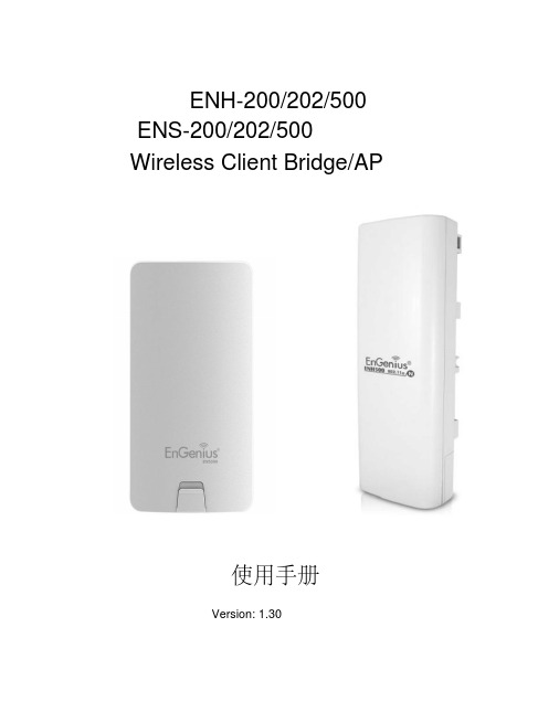
ENH-200/202/500 ENS-200/202/500Wireless Client Bridge/AP使用手册Version: 1.30一、产品介绍无线Client Bridge/Bridge Router/Access Point/WDS(wireless distribution system)工作于2.4GHz/5.8G频率,支持快速的11b/g/n (2.4GHz,300Mbps)和802.11a/g(5.8G,300Mbps)无线标准。
它为你的有线网提供了增加无线网的最好途径,或者提高你的无线网带宽。
EOC-2611P具有很高的发射功率和高接收灵敏度。
大功率和高灵敏度可以提高无线覆盖范围并且减少AP漫游时的接入设备,提高了无线连接的稳定性。
在同样的环境下,它能减少设备的费用。
为了保护你的无线网安全,它可以通过64/128位WEP加密数据,同时也支持WPA/WPA2。
MAC 过滤让你选择可以进入网络的主机。
1.1 特色 & 优点特色优点高达300Mbps传输速率有能力传输大量的数据,比如MPEG视频数据流大功率和高接收灵敏度提高传输距离和减少漫游时所需设备,提高传输稳定性点对点/点对多点无线连接让用户在两个或多个建筑间传送数据更加有效的数据安全技术支持WPA2/WPA/ IEEE 802.1xWDS (Wireless Distribution System) 使设备在作AP接入时,同时具有桥接转发的功能MAC 地址过滤(AP 模式) 保证安全的网络连接Power-over-Ethernet (IEEE802.3af) 灵活的AP安置并减少费用1.2 包装内容打开产品包装,应有如下内容:一个无线网桥/AP一个电源变压器(24V/1A)一个安装支架一张光盘和说明书一个POE供电器1.3 系统需求以下是配置设备的最小系统要求一台有网卡接口(RJ-45)的电脑有WEB浏览器的操作系统1.4 应用无线网产品是易于安装和便于使用的。
无线互动式电子白板使用手冊说明书

目錄1. 產品介紹 (2)1-1 產品簡介 (2)1-2 產品特色 (2)1-3 產品及配件 (2)1-4產品各項功能說明 (3)2. 硬體安裝說明 (4)2-1安裝架構圖 (4)2-2詳細流程步驟 (5)3. 無線互動式電子白板驅動程式、Edu Tab及無線模組安裝說明 (6)3-1安裝Microsoft Dot Net Framework (7)3-2 安裝Microsoft Windows XP Tablet PC Edition Development kit 1.7 (8)3-3 安裝Microsoft Windows XP Tablet PC Edition 2005 Recognizer Pack (僅XP需安裝) (10)3-4 安裝Touch Panel Driver (11)3-5 安裝Edu Tab (13)3-6虛擬鍵盤下載及安裝 (13)3-7虛擬鍵盤繁體中文語言套件下載及安裝 (13)3-8 安裝無線模組驅動程式 (14)3-9 無線傳輸使用說明 (16)4. Edu Tab軟體說明 (17)5. OSD (On Screen Display) 螢幕功能使用說明 (19)5-1OSD選單使用說明 (19)5-2OSD選單各項功能使用說明 (20)5-3總覽 (22)6.更新紀錄 (22)11. 產品介紹1-1 產品簡介無線互動式電子白板整合了10吋寬螢幕尺寸液晶顯示器與觸控技術,是針對教學應用而設計的解決方案。
直接在螢幕上操作,讓您以「所視即所得」的最直覺的操作方式講解授課內容,您可輕易地在數位教材上加註、畫線說明,以更清晰、更生動的教學方式與學生互動,改變傳統的教室學習方式。
此外,此無線互動式電子白板,透過無線的傳輸方式,免去電子產品最讓人頭痛的配線,讓您教學的同時也可自由地移動,使數位教學的體驗與便利性更進一步升級。
1-2 產品特色1.直覺式使用方式不同於市面一般產品,10吋互動式電子白板內建10吋寬螢幕液晶面板,對無手寫板使用經驗的使用者來說,直接於液晶面板上的輸入方式無須特別練習,是容易上手的產品。
全无线系统所用设备及说明
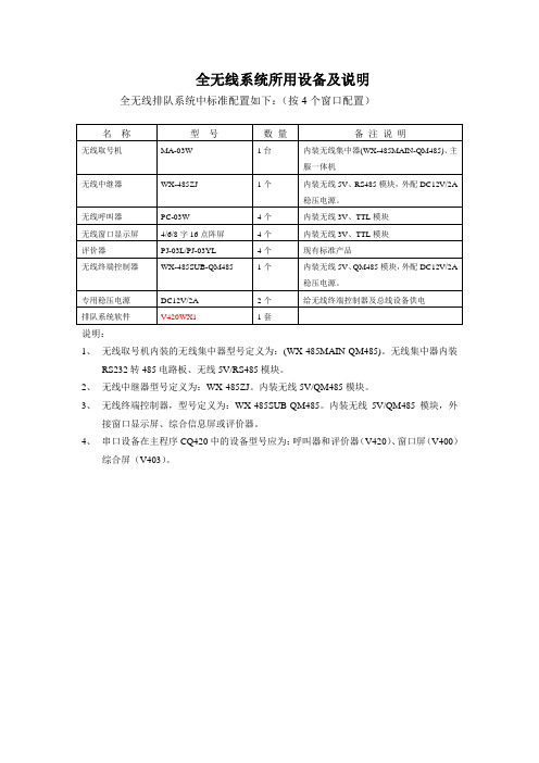
全无线系统所用设备及说明全无线排队系统中标准配置如下:(按4个窗口配置)说明:1、无线取号机内装的无线集中器型号定义为:(WX-485MAIN-QM485)。
无线集中器内装RS232转485电路板、无线5V/RS485模块。
2、无线中继器型号定义为:WX-485ZJ。
内装无线5V/QM485模块。
3、无线终端控制器,型号定义为:WX-485SUB-QM485。
内装无线5V/QM485模块,外接窗口显示屏、综合信息屏或评价器。
4、串口设备在主程序CQ420中的设备型号应为:呼叫器和评价器(V420)、窗口屏(V400)综合屏(V403)。
无线呼叫器(PC-03W)操作说明书1、呼叫器外观✓服务人员通过操作呼叫终端来为顾客办理业务;✓该呼叫器可实现重呼、转移、查询(本业务或其它业务等候人数)、插前、延后、改变柜台服务类型等多种使用功能;2、呼叫器物理特性●尺寸:95×136×45mm●型号:PC-03W●表面工艺:丝网印●材质:注朔外形●电源:两节1.5V电池●天线:内置天线●颜色:黑色●面板:16个按键,双功能转换●屏幕:8位LCD液晶显示呼叫号码●开关:后置滑动开关3、地址设定呼叫器地址设定方法:1) 调整地址方法如下:●按住“顺呼”键后,拨动后置开关,给设备上电:液晶屏显示当前地址,并进入地址设置界面;●松开“顺呼”键后,按“清屏”键,地址加1。
按“重呼”键,地址减1;2)当液晶屏上显示的地址为欲设定地址时,按“顺呼”键一下,蜂鸣器响一声(此时是设定呼叫器地址);3) 再按“登录”键,蜂鸣器响一声长声(此时是设定呼叫器内无线模块的地址);4)呼叫器断电后再通电,地址就为新设定的地址。
注意:呼叫器出厂时,初始地址为0003。
设置地址后必须重新上电,新地址才能生效。
整个网点排队系统内的呼叫器地址应该是各不相同的,否则系统出错。
4、操作功能1. 登录功能:使设备连接到系统中。
主程序设置为“简易登录”时,直接按下登录即可开始工作;主程序设置为“员工ID登录”时,输入员工ID号后按下登录即可开始工作;主程序设置为“员工ID+ 密码登录”时, 输入员工ID号后按下登录再输入个人密码,再次按下登录即可开始工作。
NETGEAR Orbi WiFi 6 System用户指南说明书

Let’s get startedT ap the Security icon in your Orbiapp to verify that your NETGEARArmor™ is activated.Download theOrbi app and installyour Orbi WiFi systemYour Orbi comes with 1 yearof free NETGEAR Armorcybersecurity. Armor blocksonline threats like hackers andphishing attempts on yourdevices.Check out everything youcan do on the Orbi app!Run a speed test, pausethe Internet, see all theconnected devices, andmore.On your mobile phone, downloadthe Orbi app and follow the setupinstructions.1Secure your deviceswith NETGEARArmorDo more with theapp3ContentsOverviewOrbi Router Orbi Satellite X 2Ethernet CablePower Adapter X 3(varies by region)Orbi Router Orbi Satellite1Sync Button2Internet Port3Ethernet Ports4Power LED5Power Connector6Reset ButtonSupport and CommunityVisit /support to get your questions answered and access the latestdownloads.You can also check out our NETGEAR Community for helpful advice at.Si ce produit est vendu au Canada, vous pouvez accéder à ce document en françaiscanadien à https:///support/download/.(If this product is sold in Canada, you can access this document in Canadian French athttps:///support/download/.)For regulatory compliance information including the EU Declaration of Conformity, visithttps:///about/regulatory/.See the regulatory compliance document before connecting the power supply.For NETGEAR’s Privacy Policy, visit https:///about/privacy-policy.By using this device, you are agreeing to NETGEAR’s T erms and Conditions athttps:///about/terms-and-conditions. If you do not agree, return thedevice to your place of purchase within your return period.NETGEAR, Inc.350 East Plumeria DriveSan Jose, CA 95134, USA© NETGEAR, Inc., NETGEAR and the NETGEAR Logo aretrademarks of NETGEAR, Inc. Any non‑NETGEAR trademarksare used for reference purposes only.NETGEAR INTERNATIONAL LTDFloor 1, Building 3,University Technology CentreCurraheen Road, Cork,T12EF21, IrelandJanuary 2021Regulatory and Legal TroubleshootingIf you’re having problems with the installation, try one of the following:• Turn off your modem and Orbi router and disconnect them. Reboot yourmodem. Reconnect your Orbi router to your modem, and try installing with theOrbi app again.• If you’re still unable to install your Orbi router using the Orbi app, manuallyinstall it using the router web interface.Visit to access the router web interface.For more information, visit /orbihelp.。
矿用无线通信系统使用说明书范文
矿用无线通信系统使用说明书范文煤矿通信系统,煤矿,矿井,广播系统煤矿通信系统,煤矿,矿井,广播系统1、概述:1.1用途KT201矿用无线通信系统做为新一代的矿井无线传输系统,采用WIFI 与TCP/IP技术相结合,在煤矿井下实现了无线数据的高速传输,为煤矿提供了一个宽带无线传输平台。
该系统根据长春东煤机电研究所企业标准《Q/DMJD30-2022KT201矿用无线通信系统》研制、生产、配套和使用,以光纤网络为骨干(接入现有工业环网或独立组网),以无线网络延伸,在煤矿井下设立若干基站,通过无线通信手段,为实现人员的语音通信、人员管理、数字化视频监控及环境监测等提供了一个共用的平台;也为实现生产调度、应急救援与安全监控与督察提供了良好的应用基础。
系统可根据用户的实际需要灵活配置,它的推广应用将使煤矿通信走上新的台阶。
KT201矿用无线通信系统可根据煤矿企业的不同需求,配备不同的功能模块从而实现不同的功能。
通过无线通信系统,可以实现煤矿企业的通信一体化、管理一体化,数据交换的一体化、数据存储与使用的一体化。
避免了采用多个单独系统所带来的数据格式不一、交换效率低下、安全性差等诸多问题。
KT201矿用无线通信系统分地面和井下两部分。
地面部分由无线控制主机、语音服务器、KJJ127矿用隔爆兼本安型环网交换机以及专用监控软件组成,可配中英文打印机、远程终端、大屏幕投影仪等设备构成功能强大的信息处理中心。
井下部分主要由KJJ127矿用隔爆兼本安型环网交换机、KT201-F矿用隔爆兼本安型无线基站、D某B18矿用隔爆型电池箱、佩带在作业人员身上的KT201-S矿用本安型手机以及矿用通信光缆等构成通信网络。
1.2系统型号含义如下图1所示:1.3使用环境条件煤矿通信系统,煤矿,矿井,广播系统1.3.1安装于地面机房、调度室的设备,环境条件须符合下列条件:1.3.1.1环境温度为15℃~30℃;1.3.1.2相对湿度为40%~70%(+25℃);1.3.1.3大气压力为80kPa~106kPa;1.3.1.4清洁、无强磁场干扰,无腐蚀性气体和无爆炸性气体。
- 1、下载文档前请自行甄别文档内容的完整性,平台不提供额外的编辑、内容补充、找答案等附加服务。
- 2、"仅部分预览"的文档,不可在线预览部分如存在完整性等问题,可反馈申请退款(可完整预览的文档不适用该条件!)。
- 3、如文档侵犯您的权益,请联系客服反馈,我们会尽快为您处理(人工客服工作时间:9:00-18:30)。
VIA Collage操作手册快速使用向导:
一、VIA设备本身的设置:
1.检查包装盒内设备及配件:
a)
b)
c)
d) VIA Collage设备一台
电源适配器一个(19V)及电源线3根
DP转H D MI适配器一个
快速使用向导说明一份
2.设备接口概览:
VIA Collage
3)
4) 连接设备
a)
b)
c)
d)
连接U SB鼠标、键
盘
通过H DMI线缆连接主显示设备,选项:通过D P转HDMI连接第二个显示设备
通过网线连接至W IFI路由器
连接电源,开启设备
配置设备:首次使用设备,可通过设备客户端中的”设置”选项来进行配置,
用户名:su 密码:supass
设置菜单中的选项:
a) 网络设置:配置V IA Collage的I P地址,使其处于路由器同一网段内,更改设置
后
需要重启V IA;默认的I P地址:192.168.1.39
b) 房间名称/密码:将房间名称更改为设备的I P地址,更改设置后需要重启
VIA
默认的房间名称:192.168.1.39
二、用户客户端设置: 1. 2.
通过 W IFI 或者有线连接终端设备(电脑, iPad,手机)到同一网络 下载安装客户端:
MAC 或者 PC : a) b) 通过 I E 浏览器,访问 V I A
的 I P 地址 选择 ”C lick to Run ”下载免安装版客户端
(一次用户使用)
选择 ”C lick to Install ”下载安装版客户端
(常用用户使用)
iOS / Android 系统的手机或 P ad:
在 A pp Store 或者
G o ogle Play 搜索 Kramer VIA ,下载免费应用 运行、登陆客户端: a) 3.
房间名称:输入 V IA 的
IP 地址
用户名:设备的昵称 密码:4位数字的密码,显示在屏幕左下
角
输入完成后,点击登陆,客户端登陆后, 进入主菜单
4. 主菜单:
a) 点击 “进入”可将终端设备的屏幕投放到主屏幕上;选择 “退出”屏幕,退
出主屏 幕显示,单个屏幕可以显示 6个画面,两个屏幕可以同时显示 12个画面;主屏幕
的显示模式,可通过主机功能菜单下的 “Display Layout ”进行更改
点击 “参与者”可查看所有加入的 V I A 平台的用户 b) c) 点击 “特性”进入子菜单,可使用菜单下的各项功
能
5. 特性菜单下功能介绍:
a) 多媒体:
i. 选择 “多媒体”选项后,可将视频文件直接拖拽到该功能下进行添加文件
也可以通过 “添加媒体文件”,将视频文件添加到该功能下 选中需要播放的文件,点击工具条上面的播放按钮,可播放文件 支持的文件格式:avi, vob, mp4, mov, mpx, mpk 等,1080P@60Hz
选中想要删除的文件,选择 ”删除媒体文件”,可将文件从列表中删除 ii.
iii.。