海康威视简易说明书完整版
海康威视监控显示器用户手册说明书

监控显示器用户手册目 录1. 责任声明 ...........................................................................................i 3. 第1章 产品简介 ................................................................................14. 第2章 设备接口................................................................................25. 第3章 面板按键................................................................................36. 第4章 遥控器 ................................................................................47. 第5章 基本操作 ................................................................................5...........................................................................................8. 保修服务 109. 限制物质或元素标识表 (11)...........................................................................................2. 前 言 i i 用户手册监控显示器版权所有©杭州海康威视数字技术股份有限公司2021。
海康威视说明书

2.3 安装DVR......................................................................................................................................................................................7
1.2 产品主要功能............................................................................................................................................................................5 2 安装指南.................................................................................................................................................................................................7
3.4 菜单项说明..............................................................................................................................................................................25
海康威视简易说明书

海康威视简易说明书海康威视iVMS-4200操作说明书前言非常感谢您购买我公司的产品,如果您有什么疑问或需要请随时联系我们。
适用型号本手册适用于网络视频监控软件iVMS-4200。
声明本手册可能包含技术上不准确的地方,或与产品功能及操作不相符的地方,或印刷错误。
我司将根据产品功能的增强或变化而更新本手册的内容,并将定期改进及更新本手册中描述的软硬件产品。
更新的内容将会在本手册的新版本中加入,恕不另行通知。
本手册中内容仅为用户提供参考指导作用,不保证与实物完全一致,请以实物为准。
约定在本手册中为了简化描述,做以下约定:网络视频监控软件iVMS-4200简称为软件。
网络硬盘录像机、、视频服务器、NVR、IP Camera和IP Dome等统一称为设备。
. iVMS-4200 简介. 功能概述软件iVMS-4200是为嵌入式网络监控设备开发的软件应用程序,适用于嵌入式网络硬盘录像机、混合型网络硬盘录像机、网络视频服务器、NVR、IP Camera、IP Dome、PCNVR和解码设备以及视音频编解码卡,支持实时预览、远程配置设备参数、录像存储、远程回放和下载等多种功能。
iVMS-4200具有以下特点:界面容器化处理模式:在客户端组件的界面设计上,精心采用容器化处理,简化了多屏和单屏切换的处理方式,大幅改善多屏操作感受,适应了一机多屏的PC发展趋势。
通道化管理模式:在客户端组件设计中,加入了通道化管理模式,抛开了以设备为核心主体的传统设计方式,更加适应于IP监控的发展方向。
用户体验为重心的界面设计:提供图片式可视化控制面板,以用户体验为重心,颠覆式的采用所需即可用的模式,提供一个功能的多个入口,以期达到最大限度减少用户操作步骤的目标。
需要才可见的显示方式:在客户端组件的界面元素上,加入了需要才可见的显示方式,在日历,时间条,工具栏,系统信息栏等多处,加入该设计模式,最大限度的节省有限的屏幕显示空间。
. 运行环境操作系统:Microsoft Windows 7/Windows 2008(支持32/64位系统)Windows 2003/Windows XP(均只支持32位系统)CPU:Intel Pentium IV GHz或以上目录前言 ............................................................................................ .. (1)iVMS-4200 简介 ............................................................................................ .. (1)功能概述 ............................................................................................ (1)运行环境 ............................................................................................ ............................................................... . (1)目录 ............................................................................................ .. (2)用户登录 ............................................................................................ (3)设备管理 ............................................................................................ (3)编码设备添加 ............................................................................................ . (3)分组 ............................................................................................ .. (5)分组添加 ............................................................................................ (6)预览 ............................................................................................ .. (7)录像配置及回放 ............................................................................................ (7)录像回放 ............................................................................................ (7)存储服务器 ............................................................................................ .. (9)存储服务器添加 ............................................................................................ (9)存储服务器配置 ............................................................................................ .. (10). 用户登录首次运行软件需要创建一个超级用户。
海康威视简易说明书完整版

海康威视简易说明书 HUA system office room 【HUA16H-TTMS2A-HUAS8Q8-HUAH1688】海康威视iVMS-4200操作说明书前言非常感谢您购买我公司的产品,如果您有什么疑问或需要请随时联系我们。
适用型号本手册适用于网络视频监控软件iVMS-4200。
声明本手册可能包含技术上不准确的地方,或与产品功能及操作不相符的地方,或印刷错误。
我司将根据产品功能的增强或变化而更新本手册的内容,并将定期改进及更新本手册中描述的软硬件产品。
更新的内容将会在本手册的新版本中加入,恕不另行通知。
本手册中内容仅为用户提供参考指导作用,不保证与实物完全一致,请以实物为准。
约定在本手册中为了简化描述,做以下约定:网络视频监控软件iVMS-4200简称为软件。
网络硬盘录像机、、视频服务器、NVR、IP Camera和IP Dome等统一称为设备。
. iVMS-4200 简介. 功能概述软件iVMS-4200是为嵌入式网络监控设备开发的软件应用程序,适用于嵌入式网络硬盘录像机、混合型网络硬盘录像机、网络视频服务器、NVR、IP Camera、IP Dome、PCNVR和解码设备以及视音频编解码卡,支持实时预览、远程配置设备参数、录像存储、远程回放和下载等多种功能。
iVMS-4200具有以下特点:界面容器化处理模式:在客户端组件的界面设计上,精心采用容器化处理,简化了多屏和单屏切换的处理方式,大幅改善多屏操作感受,适应了一机多屏的PC发展趋势。
通道化管理模式:在客户端组件设计中,加入了通道化管理模式,抛开了以设备为核心主体的传统设计方式,更加适应于IP监控的发展方向。
用户体验为重心的界面设计:提供图片式可视化控制面板,以用户体验为重心,颠覆式的采用所需即可用的模式,提供一个功能的多个入口,以期达到最大限度减少用户操作步骤的目标。
需要才可见的显示方式:在客户端组件的界面元素上,加入了需要才可见的显示方式,在日历,时间条,工具栏,系统信息栏等多处,加入该设计模式,最大限度的节省有限的屏幕显示空间。
海康威视网络摄像机用户手册格式说明书

网络摄像机操作手册V2.0.0 杭州海康威视数字技术股份有限公司技术热线:400-700-59982011-3安全须知此内容的目的是确保用户正确使用本产品,以避免危险或财产损失。
在使用此产品之前,请认真阅读此说明手册并妥善保存以备日后参考。
如下所示,预防措施分为“警告”和“注意”两部分:警告:无视警告事项,可能会导致死亡或严重伤害。
注意:无视注意事项,可能会导致伤害或财产损失。
警告事项提醒用户防范潜在的死亡或严重伤害危险。
注意事项提醒用户防范潜在的伤害或财产损失危险。
警告:1.请使用满足SELV(安全超低电压)要求的电源,并按照IEC60950-1符合LimitedPowerSource(有限电源)的额定电压为12V直流或24V交流电源(根据具体型号而定)供应。
2.如果设备工作不正常,请联系购买设备的商店或最近的服务中心,不要以任何方式拆卸或修改设备(未经许可的修改或维修所导致的问题,责任自负)。
3.为减少火灾或电击危险,请勿让本产品受到雨淋或受潮。
4.本安装应该由专业的服务人员进行,并符合当地法规规定。
5.应该在建筑物安装配线中组入易于使用的断电设备。
有关在天花板上安装设备的指示:安装后,请确保该连接至少可承受向下50牛顿(N)的拉力。
注意:1.在让摄像机运行之前,请检查供电电源是否正确。
2.请勿将此产品摔落地下或受强烈敲击。
3.请勿直接碰触到图像传感器光学元件,若有必要清洁,请将干净布用酒精稍微湿润,轻轻拭去尘污;当摄像机不使用时,请将防尘盖加上,以保护图像传感器。
4.避免对准强光(如灯光照明、太阳光等处)聚焦,否则容易引起过亮或拉光现象(这并非摄像机故障),也将影响图像传感其寿命。
5.激光束可能烧毁图像传感器,在激光装置被使用的情况下,请您一定注意不要让图像传感器的表面暴露于激光束之下。
6.避免置于潮湿,多尘,极热,极冷(正常工作温度:-10℃~+60℃),强电磁辐射等场所。
7.避免热量积蓄,请不要阻挡摄像机附近的通风。
海康威视摄像头产品用户指南说明书

How to Configure Temperature Screening ThermographicCamera1.General ParametersTemperature Measurement Range30.0-45.0 Degrees CelsiusTemperature Measurement Accuracy± 0.5 Degrees CelsiusCamera Resolution and Focal LengthDS-2TD1217B-3/PA: Thermal: 160 × 120, Optical: 2688 × 1520, 3mmDS-2TD1217B-6/PA: Thermal: 160 × 120, Optical: 2688 × 1520, 6mmDS-2TD2617B-6/PA: Thermal: 160 × 120, Optical: 2688 × 1520, 6mmDS-2TD2637B-10/P: Thermal: 384 × 288, Optical: 2688 × 1520, 10mmDS-2TD2636B-15/P: Thermal: 384 × 288, Optical: 2688 × 1520, 15mmAI Face DetectionMultiple targets skin-surface temperature detection at the same time (wearing masks or not would not affect this detection)Operating EnvironmentIndoor environment with calm air condition; 10-35 Degrees Celsius2.Installation1)Installation CautionsThe performance of this Temperature-screening scheme is greatly affected by environment. This scheme would apply only to those indoor environments, or the scenarios with calm air and consistent temperature. Besides, the relative installation location of devices and the ambient light (too bright or too dark) greatly affect the accuracy of face detection. In order to improve measurement accuracy and reach better performance of human face detection, the installation environment has to meet certain requirements:1. Select installation environments with one-direction path to ensure that camerascapture the full faces of all passing persons.2. Select installation environments with stable and sufficient lighting conditions.Supplementary light is required under backlight or insufficient lighting conditions © Hangzhou Hikvision Digital Technology Co.,Ltd. All Rights Reserved.to ensure the clear visibility of facial features.3. Select indoor environments with calm air and consistent temperature condition.Outdoor environments with rapid temperature changes are not recommended.4. If this scheme is used in entrance scenes that connect indoors and outdoorsenvironments, It is suggested that the installation location should be kept at a certain distance from the entrance (such as customs or security checkpoints).5. Avoid objects with high or low temperature placed in the scene.6. The devices should be installed firmly, thereby avoiding face detection andtemperature measurement errors caused by shaking.7. Skin-surface temperature can be affected by environment temperature, if it’s toohot and cold in outdoor environment, we recommend people to stay indoor for more than 3 minutes before temperature measurement.2)Camera InstallationThe camera should be set right in front of the one-direction path, capturing the full faces of passing persons. The installation height and the distance between the camera and measured objects is depended on the resolution and focallength of thermographic camera, as shown in the following table.There are tripods, tripod adapters, wall mount offered by HIKVISION for flexible or fixed placement, but these items require additional purchase. Only device with resolution of 384*288 is recommended to be installed on the wall.© Hangzhou Hikvision Digital Technology Co.,Ltd. All Rights Reserved.© Hangzhou Hikvision Digital Technology Co.,Ltd. All Rights Reserved.3. Configuration1) Select VCA Resource TypeSteps:1. Enter VCA Resource Type interface: Configuration > System>Maintenance>VCA Resource Type .2. Select Temperature Screening as VCA Resource Type.3. Click Save and wait for device restart.© Hangzhou Hikvision Digital Technology Co.,Ltd. All Rights Reserved.2) Set Local ConfigurationSteps:1. Go to the Local Configuration interface: Configuration > Local .2. Click to enable the following settings:Rules: It refers to the rules on your local browser; select Enable to displaybounding boxes and temperature information when the face target is detected. Display Rules Info. on Capture: Select Yes Display rules information on thecapture.Display Temperature Info.: Select Yes to display temperature information withtemperature measurement rule configured.Display Temperature Info. on Capture: Select Yes to display temperatureinformation on the capture. 3. Click Save .© Hangzhou Hikvision Digital Technology Co.,Ltd. All Rights Reserved.3) Settings of Temperature ScreeningSteps:1. Go to the Temperature Screening Settings interface: Temperature Screening > Basic Settings.2. Configure the following settings:Enable Temperature Measurement: Check this box to enable temperaturemeasurement.Display Temperature Info. on Stream: Check this box to display temperatureinformation on stream.Emissivity: The relative ability of material surface to emit energy by radiation.For human skin, this value is normally set as 0.98. Distance Mode:Set mode as ‘Self Adaption’.Distance: The actual distance between the camera and measured object. 3. Click Save .4.Go to the Temperature Screening Settings interface: Temperature Screening >Temperature Screening Configuration5.Select the optical camera channel (normally as Camera 01).6.Configure the following settings:Enable Face Detection: Check this box to enable face detection function.Display Temperature: Check this box to display measured temperature.Upload Captured Face Image: Check this box to upload captured face image.Display Face Temperature Position: Check this box to display the point with highest temperature in target frame.Configuration: Select as Targeting.Face Detection Parameters:●Set Generation Speed and Sensitivity both as 5 for best detectionperformance.●It is suggested to set Alarm When Temperature is above as 37.5 degreesCelsius and Pre-Alarm Temperature as 37 degrees Celsius, or it could beadjusted to meet other requirements.Draw Area: Draw a rectangular area; only objects in this area would be detected as targets for temperature measurement.Press Max. Pupil Distance and Min. Pupil Distance to draw width filter frame, thereby preventing false alarm caused by people’s being too close or too far. This pupil filter is actually based on the pixel width of target frame.7.Click Save.© Hangzhou Hikvision Digital Technology Co.,Ltd. All Rights Reserved.8.Select the thermal camera channel (normally as Camera 02).9.Configure the following settings:Black Body Parameters: If no blackbody is used in this scheme, uncheck this box. Body Temperature Compensation: Compensate the measured value according to the real-time environment temperature.●Enable:Check this box to enable body temperature compensation●Compensation Type: Setting as Auto is suggested; in this way, autocompensation and manual calibration value would both added to themeasured value.●Manual Calibration: The set value would be added to the measured value.(If this value is set as 2 degrees Celsius and the measured value is 35 degreesCelsius, the displayed value would be 37 degrees Celsius). See ManualCalibration part in below for details.●Environment Temperature: Setting as Auto is suggested; in this way, theenvironment temperature would be automatically measured.10.Click Save.4)Manual CalibrationPurpose:© Hangzhou Hikvision Digital Technology Co.,Ltd. All Rights Reserved.The performance of this body thermography scheme offered by HIKVISION would be affected by different actual working environments, and the affect factors in most stable environments could be regarded as a kind of system error. If needed, it is suggested to make a compensation through the manual calibration, the steps are as following.Steps:1.Device start-up; wait a period of time (more than 60 minutes) for preheating.2.For 5 to 10 individuals, complete the following 3 steps one by one:Use the ear thermometer or other specialized thermometer to get the real body temperature, and record.Use the thermographic camera to get the body temperature of the same individual, and record.Subtract these two numbers, and record the difference value.3.Set Manual Calibration with the average value of these difference values in BodyTemperature Compensation.For example:If data recorded during the calibration process are as the following table,thereby setting the Manual Calibration as 0.5 degrees Celsius.4.Other Notes for UseBefore the device is used in actual body temperature measurement, it should run for more than 60 minutes for preheating.This product is used for preliminary screening of people with Temperature. After alarm happens, specialized medical thermometer should be used in further body temperature check.© Hangzhou Hikvision Digital Technology Co.,Ltd. All Rights Reserved.First Choice for Security Professionals HIK VISION Technical Support© Hangzhou Hikvision Digital Technology Co.,Ltd. All Rights Reserved.。
海康威视录像机说明书

DS-M5504HN系列网络硬盘录像机操作手册杭州海康威视数字技术股份有限公司技术热线:400-700-59982015-06非常感谢您购买我公司的产品,如果您有什么疑问或需要请随时联系我们。
本手册适用于DS-M5504HN系列网络硬盘录像机。
本手册可能包含技术上不准确或与产品功能及操作不相符的地方或印刷错误,我司将根据产品功能的增强而更新本手册的内容,并将定期改进或更新本手册中描述的产品或程序。
更新的内容将会在本手册的新版本中加入,恕不另行通知。
安全使用注意事项使用本产品时请务必遵守以下事项:●设备安装前请先详细了解设备的电源接线方式。
●系统安装须专业汽车安装厂家或汽车厂商,安装时请尽可能将设备安置在车辆内部通风良好的位置。
●请选择硬盘生产厂商推荐的、适合设备工作要求的硬盘,以满足长时间、大数据量的读写要求;同时请从正式渠道购买,以保证硬盘的品质。
●无线网络天线以及卫星定位天线需安装在信号较好的地方且注意防雷,同时确保不要有任何物体覆盖或遮挡。
●本设备为精密电子设备,内无用户可自行维修部件,请勿私自拆装。
●若使用中有任何疑问或需要帮助,请联系海康威视或授权分销商的技术人员。
产品特点及功能产品特点●车载专用GUI界面,具备良好的用户体验性,操作简单便捷。
●录像分辨率最高支持1080P,采用H.264数字编码技术,编码效率高、策略灵活。
●支持4路IPC(或高清网络云台)接入,支持云台操作控制,提供高清车载监控视频解决方案。
●支持USB连接鼠标,可通过鼠标做设备参数配置、云台控制等操作。
●设备支持Web操作,可通过Web实现预览、回放、远程配置等功能。
●特有IPC网线接头加固设计,更适合车载环境。
●支持POE供电,方便系统搭建。
●设备能够同时接入2块2.5英寸HDD/SSD硬盘,硬盘接入方式为可插拔式,并采用具有自主知识产权的航空气囊减振专利技术。
●硬盘盒自带风扇,可实现智能温控,并具有USB数据导出功能。
海康威视Nvr1系列Nvr2系列Nvr4系列网络硬盘录像机使用说明书

网络硬盘录像机使用说明书V2.7.2前言概述本文档详细描述了NVR(Network Video Recorder)设备的安装、使用方法和界面操作等。
适用型号:型号系列具体型号NVR1系列NVR104、NVR104-P、NVR108、NVR108-P、NVR1104、NVR1104-P、NVR1108、NVR1108-P、NVR1104H、NVR1104H-P、NVR1108H、NVR1108H-P、NVR1104HS、NVR1108HSNVR2系列NVR2104HS-S1、NVR2108HS-S1、NVR2116HS-S1、NVR2104HS-P-S1、NVR2108HS-8P-S1、NVR2204-S1、NVR2208-S1、NVR2216-S1、NVR2204-P-S1、NVR2208-8P-S1NVR4系列NVR4104H、NVR4104H-P、NVR4108H、NVR4108H-P、NVR4116H、NVR4116H-P、NVR4104H-W、NVR4104H-4G、NVR4108H-4G、NVR4104、NVR4108、NVR4116、NVR4104-P、NVR4108-P、NVR4116-P、NVR4204、NVR4204-P、NVR4208、NVR4208-8P、NVR4208-P、NVR4216、NVR4216-8P、NVR4216-P、NVR4232、NVR4208-4K、NVR4216-4K、NVR4216-16P、NVR4232-16P、NVR4232-4K、NVR4408、NVR4408-8P、NVR4416、NVR4432、NVR4408-4K、NVR4416-4K、NVR4432-4K、NVR4416-16P、NVR4808、NVR4816、NVR4832、NVR4808-4K、NVR4816-4K、NVR4832-4K、NVR4104HS-HDS2、NVR4108HS-HDS2、NVR4116HS-HDS2、NVR4104HS-P-HDS2、NVR4108HS-8P-HDS2、NVR4104HS-4KS2、NVR4108HS-4KS2、NVR4116HS-4KS2、NVR4104HS-P-4KS2、NVR4108HS-8P-4KS2、NVR4208-HDS2、NVR4216-HDS2、NVR4232-HDS2、NVR4208-8P-HDS2、NVR4216-16P-HDS2、NVR4208-4KS2、NVR4208-8P-4KS2、NVR4216-4KS2、NVR4216-16P-4KS2、NVR4232-4KS2、NVR4408-HDS2、NVR4416-HDS2、NVR4432-HDS2、NVR4416-16P-4KS2、NVR4416-16P-HDS2、NVR4408-4KS2、NVR4416-4KS2、NVR4432-4KS2、NVR4808-HDS2、NVR4816-HDS2、NVR4832-HDS2、NVR4808-4KS2、NVR4816-4KS2、NVR4832-4KS2NVR5系列NVR5808-4K、NVR5816-4K、NVR5832-4K、NVR5864-4K、NVR5064-4K、NVR5032-4K、NVR5016-4K、NVR5408-4K、NVR5416-4K、NVR5432-4K、NVR5464-4K、NVR5208-4K、NVR5216-4K、NVR5232-4K、NVR5264-4K、NVR5016FG-4K、NVR5032FG-4K、NVR5064FG-4KNVR7系列NVR7032、NVR7032-R、NVR7064、NVR7064-R、NVR7808、NVR7816、NVR7832、NVR7864、NVR7816-16P、NVR7832-16P、NVR7864-16P、NVR7816-RH、NVR7832-RH、NVR7864-RH、NVR7408、NVR7416、NVR7432、NVR7464、NVR7208、NVR7208-8P、NVR7216、NVR7216-8P、NVR7232、NVR7232-8PNVR8系列NVR808-8-HD、NVR808-16-HD、NVR808-32-HD、NVR816-32-HD、NVR816-64-HD 符号约定在本文中可能出现下列标志,它们所代表的含义如下:图标说明危险表示有高度潜在危险,如果不能避免,会导致人员伤亡或严重伤害。
海康威视4200简易说明手册
精心整理海康威视iVMS-4200操作说明书前言非常感谢您购买我公司的产品,如果您有什么疑问或需要请随时联系我们。
适用型号声明✍✍将根✍✍ 约定✍✍✍✍.软件混合编解码✍✍切换的处理方式,大幅改善多屏操作感受,适应了一机多屏的PC 发展趋势。
✍✍通道化管理模式:在客户端组件设计中,加入了通道化管理模式,抛开了以设备为核心主体的传统设计方式,更加适应于IP 监控的发展方向。
✍✍用户体验为重心的界面设计:提供图片式可视化控制面板,以用户体验为重心,颠覆式的采用所需即可用的模式,提供一个功能的多个入口,以期达到最大限度减少用户操作步骤的目标。
✍✍需要才可见的显示方式:在客户端组件的界面元素上,加入了需要才可见的显示方式,在日历,时间条,工具栏,系统信息栏等多处,加入该设计模式,最大限度的节省有限的屏幕显示空间。
.运行环境✍✍操作系统:MicrosoftWindows7/Windows2008(支持32/64位系统)✍✍Windows2003/WindowsXP(均只支持32位系统)✍✍CPU:IntelPentiumIV3.0GHz或以上目录前言 (1)iVMS-4200简介 (1)功能概述 (1)运行环境 (1)目录用户登录设备管理分组分组添加预览录像回放...控制面板中选择,进入设备管理界面。
首次使用软件,需要先添加设备。
下面在线设备中显示当前局域网所有在线的编码设备,如图所示。
点击,或按住Ctrl键选择在线设备的某几台设备,点击,弹出添加设备对话框如图所示。
输入用户名密码,点击“添加”即可完成局域网全部设备或批量设备的添加局域网添加设备对话框如图所视输入别名、用户名、密码,点击“添加”即可完成局域网在线设备的添加。
点击,可修改在线设备网络参数,如图所示。
该界面可修改设备的网络参数,修改IP、掩码、端口号,输入设备管理员密码,点击“确定”,即可完成设备的网络参数修改。
点击,弹出对话框如图所示。
输入正确的验证码,点击“确定”即可恢复设备缺省密码。
海康威视DVR设备操作手册说明书

Step 17. Enter Alarm 1 Enable/Disable Submenu Press d to display flashing DSBL / ENBL .Step 18. Enable Alarm 1 SubmenuIf flashing ENBL is displayed, press a , if DSBL is displayed,press b until ENBL is displayed, then press d to store and go to the next menu item.Step 19. Select the Deviation Control Type Submenu Press d . If flashing _DEV Deviation is displayed press a ,otherwise press b until flashing _DEV is shown. Now press d to store and go to next menu item.Step 20. Select the Latched Type SubmenuPress d . If flashing UNLT Unlatched is displayed press a ,otherwise press b until UNLT is displayed.Press d to store and advance to next menu item.Step 21. Select the Normally Open Type of Contact Closure SubmenuPress d . If flashing N.o.Normally Open is displayed,press a , otherwise press b until N.o.is displayed. Press d to store and advance to next menu item.Step 22. Select the Above Type of Active Submenu Press d . If flashing ABoV Above is displayed, press a ,otherwise press b until ABoV is displayed. Press d to store and advance to next menu item.Step 23. Enable Alarm 1 at Power On (A.P.oN )Press d . If flashing ENBL is displayed, press a , otherwise press b until ENBL is displayed. Press d to store and advance to next menu item.Step 24. Enter Alarm 1 High SubmenuPress a twice to skip ALR.L Alarm 1 Low value. ALR.L is for below & ALR.H for above.Step 25. Set the Alarm 1 High value (ALR.H )Press d . Press b or c until value to set the display to 002.0. Press d to save.Step 26. Enter the Alarm 2 MenuThe display will show ALR2the top menu for Alarm 2.Repeat steps from 17 to 25 to set for Alarm 2 the same conditions as for Alarm 1.Step 27. Skip the Loop Break Time Menu (LOOP )Press a to go to the OUT1Output 1 Menu item.Step 28. Configuration the Output 1 MenuSet Alarm 1 Disabled (Step 18) to be able to Enable Output 1.Step 29. Configuration of Display Color Selection Press a until the COLR Display Color Selection Menu appears on the Display. Configure COLR as N.CLR /GRN (green), 1.CLR / RED (red), 2.CLR /AMBR (amber). Please refer to the operator’s manual if needed.For color change on Setpoints refer to Owners Manual Section 2.MQS4007/0411SPECIFICATIONSENSOR SPECIFICATIONSRelative Humidity Accuracy/Range:±2% for 10 to 90%±3% for 5 to 10% and 90 to 95%±4% for 0 to 5% and 95 to 100%Non-linearity : ±3%Hysteresis: ±1% RH Response Time :8 sec, tau 63%Repeatability : ±0.1%Resolution : 0.1%, 12bitTemperature Accuracy/Range*:±0.5°C for 5 to 45°C (±1°F for 41 to 113°F); up to ±1.5°C for -40 to 5°C and 45 to 124°C (up to ±2.7°F for -40 to 41°F and 113 to 257°F)*NOTE:extended temp range is for Probe only, the Controller’s operating temp is 0-50°CResponse Time : 5 to 30 sec, tau 63%Repeatability : ±0.1°C Resolution : 0.1°C, 14 bit METER SPECIFICATIONS Display:4-digit, 9-segment LED, •10.2 mm (0.40")Red, green, and amber programmable colors for setpoint and temperature units.Output 1†:Relay 250 Vac @ 3 A Resistive Load,SSR, Pulse Output 2†:Relay 250 Vac @ 3 A Resistive Load,SSR, Pulse †Only with -AL Limit Alarm optionOptions:Communication RS-232 / RS-485or Excitation:24 Vdc @ 25 mAExc. not available for Low Power OptionLine Voltage/Power:90 - 240 Vac ±10%,50 - 400 Hz*, or 110 - 375 Vdc, 4 W* No CE compliance above 60 HzLow Voltage Power Option:12 - 36 Vdc or 24 Vac** ±10%, 3 W**Units can be powered safely with 24 Vac but No Certification for CE/UL are claimed.Dimensions:25.4 H x 48 W x 126.3 D mm (1.0 x 1.89 x 5")Weight:127 g (0.28 lb)Approvals:CE per EN61010-1:2001It is the policy of OMEGA to comply with all worldwide safety and EMC/EMI regulations that apply.OEMGA is constantly pursuing certification of its products to the European New Approach Directives.OMEGA will add the CE mark to every appropriate device upon certification.The information contained in this document is believed to be correct, but OMEGA Engineering,Inc.accepts no liability for any errors it contains, and reserves the right to alter specifications without notice.TRADEMARK NOTICE:®,®,, andare Trademarks ofOMEGA ENGINEERING, INC.®This Quick Start Reference provides informationon setting up your instrument for basic operation.The latest complete Communication and OperationalManual as well as free Software and ActiveX Controlsare available at /specs/iseriesor on the CD-ROM enclosed with your shipment. SAFETY CONSIDERATIONThe instrument is a panel mount device protected in accordance with EN61010-1:2001. Remember that the unit has no power-on switch. Building installation should include a switch or circuit-breaker that must be compliant to IEC 947-1 and 947-3.SAFETY:•Do not exceed voltage rating on the label located onthe top of the instrument housing.•Always disconnect power before changing signal andpower connections.•Do not use this instrument on a work bench withoutits case for safety reasons.•Do not operate this instrument in flammable orexplosive atmospheres.•Do not expose this instrument to rain or moisture. EMC:•Whenever EMC is an issue, always use shielded cables.•Never run signal and power wires in the same conduit.•Use signal wire connections with twisted-pair cables.•Install Ferrite Bead(s) on signal wire close to theinstrument if EMC problems persist.MOUNTINGPanel Mounting Instruction:ing the dimensions from the panel cutout diagramshown above, cut an opening in the panel.2.Insert the unit into the opening from the front of thepanel, so the gasket seals between the bezel and thefront of the panel.3.Slide the retainer over the rear of the case and tightenagainst the backside of the mounting panel.。
海康威视 网络视频录像机 用户手册说明书

网络视频录像机用户手册V3.01目录关于本文档 (1)1 操作必读 (2)1.1 本地操作必读 (2)1.2 本地界面操作方法 (2)2 初始配置 (5)2.1 开机准备 (5)2.2 自动添加 (5)2.3 设备登录 (6)2.4 开机向导 (9)3 预览 (11)3.1 预览界面状态 (12)3.2 窗格工具栏 (12)3.3 底部工具栏 (13)3.4 右键菜单栏 (17)4 通道配置 (20)4.1 通道管理 (20)4.1.1 IPC配置 (20)4.1.2 鱼眼配置 (27)4.1.3 高级配置 (29)4.2 编码参数 (30)4.3 音频配置 (32)4.4 抓图参数 (33)4.5 OSD配置 (34)4.6 图像参数 (35)4.7 隐私遮盖 (39)4.8 云台配置 (41)5 智能分析 (46)5.1 智能功能配置 (46)5.1.1 联动方式 (47)5.1.2 布防计划 (54)5.1.3 人脸检测 (55)5.1.4 人脸比对 (57)5.1.5 越界检测 (60)5.1.6 区域入侵 (63)5.1.7 进入区域 (65)5.1.8 离开区域 (67)5.1.9 智能运动检测 (69)5.1.11 高空抛物 (71)5.1.12 虚焦检测 (73)5.1.13 场景变更 (73)5.1.14 物品搬移 (74)5.1.15 物品遗留 (75)5.1.16 自动跟踪 (76)5.1.17 人流量统计 (77)5.1.18 人员密度检测 (78)5.2 分析器配置 (80)5.3 名单库管理 (80)5.3.1 人脸名单 (80)5.4 车辆管控 (83)5.4.1 车牌名单 (83)5.4.2 车辆报警布控 (85)5.5 智能检索 (86)5.5.1 人脸抓拍检索 (86)5.5.2 人脸比对检索 (87)5.5.3 以图搜图 (90)5.5.4 车辆检索 (93)5.5.5 行为检索 (95)5.5.6 人数统计报表 (98)5.6 智能预览 (99)6 网络配置 (104)6.1 常规配置 (104)6.1.1 网络配置 (104)6.1.2 宇视云 (105)6.1.3 DDNS (109)6.1.4 邮件 (110)6.2 平台配置 (111)6.2.1 国标服务器配置 (111)6.2.2 国标本地配置 (114)6.2.3 UNP (114)6.2.4 监管平台 (116)6.2.5 SNMP (117)6.2.6 报警上报 (119)6.2.7 视图库GA/T1400本地配置 (120)6.2.8 视图库GA/T1400服务器配置 (121)6.2.9 CDN(流分发)管理 (122)6.2.10 TMS配置 (123)6.3 高级配置 (124)6.3.1 拨号上网 (124)6.3.2 端口 (125)6.3.3 端口映射 (126)6.3.4 组播 (127)6.3.5 FTP (128)6.4 无线局域网 (130)7 系统配置 (130)7.1 基本配置 (130)7.2 预览配置 (131)7.2.1 预览配置 (131)7.2.2 高级配置 (134)7.3 时间配置 (134)7.3.1 时间配置 (134)7.3.2 时间同步 (135)7.3.3 假日配置 (135)7.4 POS配置 (137)7.4.1 POS显示配置 (137)7.4.2 POS配置 (138)7.5 串口配置 (140)7.6 用户配置 (141)7.7 安全配置 (142)7.7.1 IP地址过滤 (142)7.7.2 ONVIF认证 (143)7.7.3 802.1x (143)7.7.4 ARP防攻击 (144)7.7.5 视频水印 (144)7.7.6 安全密码 (144)7.8 热备配置 (145)8 备份 (147)8.1 录像备份 (147)8.2 图片备份 (150)9 存储配置 (153)9.1 录像计划 (153)9.2 抓图计划 (156)9.3 阵列配置 (157)9.4 硬盘管理 (161)9.5 盘组配置 (163)9.6 容量配置 (164)9.7 高级配置 (165)10 报警配置 (166)10.1 运动检测 (166)10.2 遮挡检测 (167)10.3 人形检测 (167)10.4 视频丢失 (168)10.5 输入输出 (169)10.5.1 报警输入 (169)10.5.2 报警输出 (171)10.6 热成像检测 (173)10.7 温度异常 (175)10.8 异常配置 (176)10.9 声音检测 (177)10.10 蜂鸣器 (178)10.11 门铃呼叫 (179)10.12 滞留人数告警 (179)10.13 一键撤防 (181)10.14 手动报警 (183)11 系统维护 (184)11.1 系统信息 (184)11.1.1 基本信息 (184)11.1.2 通道状态 (184)11.1.3 录像状态 (185)11.1.4 在线用户 (185)11.1.5 硬盘状态 (186)11.1.6 解码卡状态 (186)11.2 网络信息 (187)11.2.1 网络流量 (187)11.2.2 网络抓包 (187)11.2.3 网络检测 (189)11.2.4 网络状态 (191)11.2.5 网络资源统计 (191)11.2.6 PoE/交换网口状态 (192)11.3 日志查询 (192)11.4 系统备份 (194)11.4.1 系统备份 (194)11.4.2 诊断信息 (194)11.5 系统恢复 (196)11.6 自动维护 (196)11.7 系统升级 (196)11.7.1 NVR升级 (197)11.7.2 IPC升级 (198)11.8 硬盘检测 (199)11.8.1 S.M.A.R.T.检测 (199)11.8.2 磁盘检测 (200)11.9 关于我们 (200)11.10 一键收集 (201)12 回放 (201)12.1 即时回放 (202)12.2 普通回放 (202)12.3 智能回放 (204)12.4 走廊回放 (206)12.5 外部文件回放 (206)12.6 标签回放 (206)12.7 检索回放 (208)12.8 文件管理 (209)13 关机 (210)14 Web操作 (210)14.1 登录前准备 (210)14.2 登录 (211)14.3 实况 (211)14.4 回放 (212)14.5 配置 (213)14.6 智能 (214)15 附录:常见问题解答 (214)关于本文档版权声明©2022浙江宇视科技有限公司。
海康威视无线路由器用户手册说明书
轻松管理路由器
系统要求:
苹果手机iOS8.0及以上版本安卓手机4.0及以上版本
设备接入互联网可能面临网络安全问题,请您加强个人信息及数据安全的保1、凭此卡享受保修期内的免费保修及保修期外的优惠性服务。
适用场景:旧路由器的联网方式为宽带拨号。
如果没有出现上述页面,请参考常见问题解答的问系统默认将登录密码设置成与无线密码相同,如果需要自定义,请取消勾选“将无线密码同时设置为登录密码”,然后设置。
如果不能上网,请参考常见问题解答的问手机等无线设备连接页面显示的无线网络,输入无线密码即可上网。
用网线连接到路由器1、2、3/IPTV 口的电脑等设备可直接上网了。
:手机等无线设备连接到路由器的无线网络。
可在路由器底面贴纸查看。
无线路由器
本路由器支持。
海康威视操作说明

监控操作说明一、安全使用注意事项使用本产品时请务必遵守以下事项:⏹ 硬盘录像机上不能放置盛有液体的容器(例如水杯)。
⏹ 将硬盘录像机放置在通风良好的位置。
⏹ 使硬盘录像机工作在允许的温度及湿度范围内。
⏹ 硬盘录像机内电路板上的灰尘在受潮后会引起短路,请定期用软毛刷对电路板、接插件、机箱及机箱风扇进行除尘。
⏹ 电池更换不当会有爆炸危险,不建议用户直接更换;如需更换,只能用同样类型或等效类型的电池进行更换。
二、前面板介绍序号说明1 状态灯1-16 通道1-16 状态显示:绿色表示正在录像,红色表示正在网传,橙色表示既在录像又在网传。
(如发现状态不亮,请联系技术人员)2 显示屏信息显示屏显示系统当前信息。
3 USB USB 接口连接USB 存储设备,如用于备份或升级。
可以热插拔4 开关键开关键设备开关,带电源指示灯,绿色表示设备正在工作,红色表示设备已经停止工作,指示灯灭表示后面板电源开关已经关闭或电源线已经拔掉5 输入键1-16 可以输入数字、大小写英文字母、符号及汉字(区位码)F1/灯光灯光控制键F2/辅助控制辅助设备6 状态灯就绪设备处于就绪状态。
状态处于遥控器控制时呈绿色,处于键盘控制下呈红色报警有报警信号输入时呈红色MODEM 当通过RS-232 串口连接的MODEM 拨号成功后呈绿色。
硬盘硬盘正在读写时呈红色并闪烁网络网络连接正常时呈绿色网传网络正在发送/接收数据时呈绿色并闪烁7 复合键主菜单/雨刷 1、到菜单操作界面的切换;2、雨刷控制。
放像/自动 1、本地回放;2、自动扫描。
退出取消当前操作,返回到上级菜单或预览界面。
录像/预置点 1、手动录像;2、调用预置点编辑/光圈 1、进入编辑状态,在编辑状态下用于删除光标前字符;2、选择框状态 与×之间的切换; 3、调整光圈云台控制/光圈- 1、进入云台控制模式;2、调整光圈输入法/焦距+ 1、输入法(数字、英文、中文、符号)之间的切换;2、调整焦距;3、本地预览界面中,显示/隐藏通道状态。
海康威视 CCTV 摄像机产品说明书

1. Backnu t1.1 Rear Compression Spigot 1.2 Rear Seal2. Middle N u t3. Pot Cap4. R u bber Pot5. EntryAStrip Cable to suit equipment as shown above,removing all cable fillers.Length I to suit equipment.If required, fit shroud.See Notes re. Drain Wires.BPosition rear of pot cap level with prepared face of cable insulation, ensuring that the cap remains concentric to cable at all times.Shroud OptionCompoundCable Preparation Gland PreparationCSpread the cable cores out for the compound packing. Pack the compound between the cores as shown.See notes overleaf and Fig. 7 for compound preparation.Operating temperature range -60°C +80°CGland Type: ICG 623Exdb IIC Gb / Exeb IIC Gb / Extb IIIC Db Baseefa06ATEX0058X II 2 GD IP66IECEx BAS06.0015X IEx 14.0272XEAC ТC RU C-GB.ГБ05.B.00750c CSA us No: 1024328 Class 1 Zone 1 AExd IIC, AExe II, Zone 21 AExtD Class 1 Div 2 ABCD, Class II Div 2 Groups EFG, Class III CNEx12.3448XCertification DetailsAI 305 - Issue U / Page 1 of 4AI 305 / Issue U - 06/17Assembly Instructions for cable gland:ICG 623I34521 1.11.223133Product supplied may differ slightly from that shown.Images are for illustrationpuproses only.EReplace the entry ⑤ over the rubber pot ④ ensuring that compound does not cover end of rubber pot ④ FLocate and hand tighten the sub-assembly ① and ② to the entry ⑤.GTo further locate and support the compoundand rubber pot assembly, while holding the middle nut ② with a spanner/wrench, tighten the backnut ① until the seal grips the cable to prevent movement of the cable gland.IMPORTANT NOTE: The conductors must not be moved for a minimum of four hours.HAllow the compound to cure.(See Fig. 7 for Curing Times).Untighten firstly the backnut ① from ② and secondly the middle nut ② from the entry ⑤.The rubber pot ④ may be removed for inspection to ensure that the packing is satisfactory. Add further compound if necessary.IRe-assemble rubber pot ④ and the entry ⑤.Tighten the sub-assembly ① and ② to the entry ⑤and add half a turn to ② with a spanner/wrench.Tighten the backnut ① to form a seal around the cable, then tighten a further full turn using a spanner/wrench. Ensure that the middle nut ② does not rotate when tightening the backnut ①.Locate the shroud over the cable gland if applicable.TapeRemove surplus compoundRemovesurplus compoundRemovesurplus compoundCompoundDWith all gaps and voids filled, bring the conductors back together and pack more compound around the outside of the conductors. Tape the conductors together to prevent disturbance of the compound seal.Pass the rubber pot ④ over pot cap ③ and remove any surplus compound from the top of rubber pot ④ and joint faces as indicated.AI 305 - Issue U / Page 2 of 435mm43541252453215211EPOXY COMPOUND PREPARATIONWhen handling this material, the gloves supplied must be worn. The epoxy compound is supplied in the form of a two part package. These should be mixed into the ratio of 1:1 until both colours have blended into one, without any streaks. Rolling and folding is the most satisfactory method of obtaining an even blend. Once mixed, the compound must be used within 30 minutes. After this time it will begin to stiffen. The compound should be kept at an ambient temperature of no less than 20°C prior to using. At lower temperatures it becomes difficult to mix. Should any compound come into contact with the skin it should be cleaned off with skin cleaner and not allowed to dry on the skin. Only compound for immediate terminations should be mixed.The mixing and installation of the compound at an ambient temperature below 4°C is not recommended due to extended curing period.The storage of the compound shall be at temperatures between 5°C and 30°C.● The compound may be adversely affected by some solvent vapours. If such vapours are likely to be present in the vicinity of the cable gland in service, suitable precautions may be necessary. (Contact Hawke's Technical Dept).● The compound cures at a Shore D hardness of 85, when it can be handled. The compound when fully cured is suitable for use at a temperature range of -60°C to +80°C.AI 305 - Issue U / Page 3 of 41.0 INSULATING DRAIN WIRES WITH HEAT SHRINK OR COLD SHRINK TUBING 1.1 Fold back the armour / braid and bend it to right angles from the inner sheath. 1.2 Remove foils and tape level with the outer sheath, exposing the drain wires and insulated conductors. Cut back a further 10mm of inner sheath. 1.3 Pass 100mm length of heat shrink or cold shrink tubing over the drain wire until it comes into contact with the foils, then shrink the tubing evenly down onto the drain wire so that no air pockets occur. 1.4 To insulate the joint between the foils and the tubing a suitable piece of 10mm long shrink tubing or neoprene stretch tubing or a 10mm wide lap of PVC tape may be used. 1.5 After completing 1.1 to 1.4 on each drain wire, lay the armour / braid parallel to the cable, if applicable, then carry out instruction B.DRAIN WIRE PREPARATIONThe following instructions are the various BASEEFA approved methods of passing drain wires etc. through the compound barrier and should be followed if permitted by cable installation specifications.2.0 INSULATING DRAIN WIRES / SCREENS WITH SEPARATE INSULATED CRIMPED CONDUCTORS OR SOLDERED CONNECTION 2.1 Fold back the armour / braid and bend to right angles from the inner sheath. 2.2 Remove a further 15mm of inner sheath (See Fig. 1). 2.3 Unravel one or two groups of wires from the screen wires, then remove the remainder of the screen wires (See Fig. 2). 2.4 Twist the group of screen wires into a pigtail and cut to 15mm long. 2.5 Crimp an insulated conductor to the pigtail wih a suitable insulated butt ferrule (or soldered connection), leaving enough length of the insulated conductor to enable the remote end to be connected to the earth terminal in the equipment. (See Fig. 3). Note: There shall be a minimum of 10mm of compound on both ends of the crimped / soldered joint. 2.6 To insulate the joint between the screen wires and the insulated conductor, place one lap of PVC insulating tape over the exposed metallic joint. 2.7 After completing 2.1 to 2.6 on each drain wire, lay the armour / braid parallel to the cable. Then carry out instruction B.3.0 INSULATING DRAIN WIRES WITH INSULATING VARNISH OR PAINT 3.1 Fold back the armour / braid and bend it at right angles from the inner sheath. 3.2 Remove the foil and tape level with the inner sheath exposing the drain wires and conductor pairs. 3.3 Cut back a further 10mm of inner sheath (See Fig. 4). 3.4 Spray or paint the drain wires with insulating varnish or paint, then leave to dry (See Fig. 5) 3.5 To insulate the foil ends a suitable piece of 10mm long shrink tubing or neoprene stretch tubing or a 10mm wide lap of PVC tape may be used (See Fig. 6).3.6 After completing 3.1 to 3.5 on each drain wire, lay the armour / braid parallel to the cable. Then carry out instruction B.Outer SheathArmour / braidArmour / braid15mm10mmInner Sheath One or two groupsof screen wiresInsulated ConductorCrimp or SolderScreen WiresInner Sheath FoilsDrain WireInsulatedDrain WireSleevingFig. 1Fig. 2Fig. 3Fig. 6Fig. 5Fig. 41289080706050403020100S h o r e H a r d n e s sTime (Hours)40 ºC 25 ºC 4 ºC416Epoxy CompoundCure Time Vs. TemperatureFig. 7ACCESSORIES:Before cable gland assembly or stripping of the cable gland assembly, consideration should be given to any cable gland accessories that may be required, such as: -● Shroud, to offer additional corrosion protection.● Locknut, to secure cable glands into position.● Sealing washer, to offer additional ingress protection of the enclosure at the cable gland entry.●Serrated washer, to dampen any vibrations that may loosen the locknut or cable gland assembly.SCHEDULE OF LIMITATIONS - Baseefa ATEX / IECEx:1. These glands are suitable for use within an operating temperature range of -60°C to +80°C.2. When the gland is used for increased safety, the entry thread shall be suitably sealed to maintain the ingress protection rating of the associated enclosure.AI 305 - Issue U / Page 4 of 4CABLE GLAND SELECTION TABLEEntry ThreadSizeMetric Size Ref.NPT Across Flats Across Corners Hexagon Dimensions O A B C C2D E FM20M20M25M32M40M50M63M7511.016.221.926.337.147.859.012.518.424.729.741.753.565.3/66.224.030.036.046.055.065.080.095.026.532.539.550.560.670.888.0104.0Inner Sheath/CoresOuter SheathMax.Cable Acceptance Details8.910.0426080100120Min.Max.Min.Standard Seal Alternative Seal (S)7.511.013.019.025.031.542.554.511.914.320.226.532.544.456.368.28.59.515.522.027.539.048.513.415.421.228.034.846.558.3---Os M2024.056.455.858.862.064.572.877.080.756.466636870728790926626.58.08.0 3.08.0---------½" - ¾"2" - 2½"2½" - 3"½"½"¾" - 1"1" - 1¼"1¼" - 1½"1½" - 2"Max.Over Cores Max.Inner Sheath C o m p r e s s e d L e n g t hM a x i m u m L e n g t h12153012Max. No.of Cores NOTES - c CSA us:1. Class 1 Division 2 suitable for Marine Shipboard applications only according to CSA Standard 245 and IEEE45 / IEC 600092-353 Standards, or certified equivalent,for use on Shipboards and Offshore Rigs / Platforms only.2. Glands must comply with the Canadian Electrical Code and National Electric Code requirements for threaded entries.3. For Exe applications, a sealing washer or thread sealant may be required between the enclosure and the gland to maintain the IP rating of the enclosure.4. Drain wires and earth screening may pass through the compound barrier using one of the methods which are details in this assembly instruction; heat shrink orcold shrink tubing, or addition of an insulated crimped or soldered conductor or insulation by varnish or paint.5. This cable gland may only be installed when temperature is above +4°C. After completion of the installation, the assembly is then suitable for -60°C to +80°C.EU Declaration of Conformity in accordance with European Directive 2014/34/EU Manufacturer: Hawke InternationalAddress: Oxford Street West, Ashton-under-Lyne, OL7 0NA, United Kingdom Equipment: Group II Barrier Cable Glands Type: ICG 623Provisions of the Directive fulfilled by the Equipment: Group II Category 2GD Exeb IIC Gb, Exdb IIC Gb, Extb IIIC Db – IP66Notified Body for EU-Type Examination: SGS-Baseefa 1180 Buxton UK EU-type Examination Certificate: Baseefa06ATEX0058X Notified Body for production: SGS-Baseefa 1180 Buxton UKHarmonised Standards used: EN 60079-0:2012+A11:2013, EN60079-1:2014, EN60079-7:2015, EN60079-31:2014On behalf of the above named company, I declare that, on the date the equipment accompanied by this declaration is placed on the market, the equipment conforms with all technical and regulatory requirements of the above listed directives.………………………………….A. TindallTechnical Manager……………………………。
海康威视使用说明

灯
Tx/Rx 网络正在发送/接收数据时呈绿色并闪烁。
后面板物理接口
后面板物理接口说明
序号
物理接口
连接说明
视频输入(VIDEO IN)
连接(模拟)视频输入设备,标准BNC接口。
1
音频输入(AUDIO IN)
连接(模拟)音频输入设备,标准BNC接口。其中DS8016HTS为视频环通输出。
录像资料备份
录像资料备份操作要求用户具有“回放”操作权限。在进 行备份操作以前,请先连接好备份设备,如U盘、USB硬盘 或USB刻录机、IDE刻录机等备份设备。
录像资料的备份是在回放操作界面中进行,所以首先需要 进入回放操作界面。如果是在预览模式下,那么按前面板 【放像/PLAY】键,在弹出的登录对话框中选择一个用户名 并输入正确的密码可进入回放操作界面。如果在菜单操作 模式下,则按前面板【放像/PLAY】键可直接进入回放操作 界面。
报警输出(OUT) 接报警输出(4路开关量,连接方法介绍参 见2.4节)。
8
电源
通过开关可以选择输入的交流电压为220V或
110V。
菜单操作方法
按【主菜单/MENU】键,进入设备主菜单界 面。
按【放像/PLAY】快捷键,进入回放操作界面。 按【录像/REC】快捷键,进入手动录像操作
界面。 按【云台控制/PTZ】快捷键,进入云台控制
通过【】、【】键可以移动光标位置。 通过【编辑/EDIT】键可以删除光标前的字符。 按【确认/ENTER】键或【退出/ESC】键可以退出编辑状态。 按钮:用作执行一个特定功能或进入下一级设置菜单,如“处理方式” 可进入下一级设置菜单。在下级菜单中,按“确认”保存设置参数并 返回上 级菜单,按【退出/ESC】键或选择“取消”放弃设置参数并返 回上级菜单。有的按钮是灰色的,说明该按钮目前被屏蔽掉了,在被 激活以前不可被操作。
海康硬盘录像机简易操作说明书
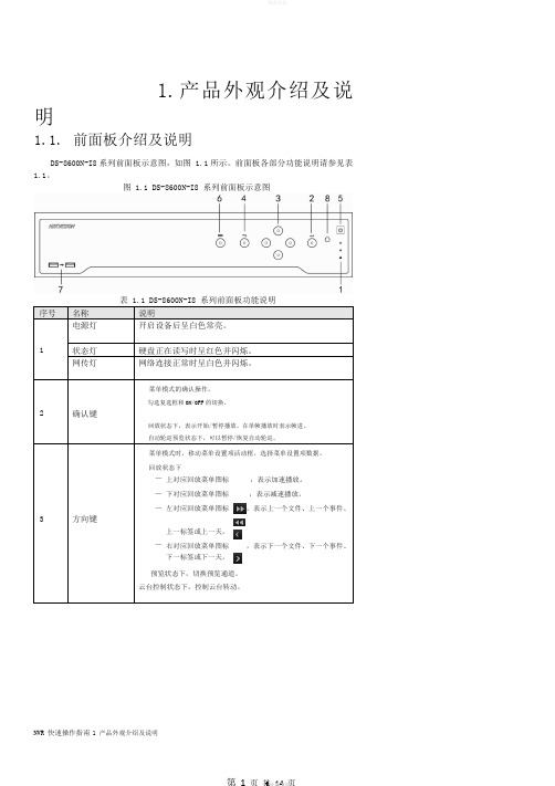
1.产品外观介绍及说明1.1.前面板介绍及说明DS-8600N-I8系列前面板示意图,如图 1.1所示。
前面板各部分功能说明请参见表1.1。
图 1.1 DS-8600N-I8 系列前面板示意图序号名称说明电源灯开启设备后呈白色常亮。
1 状态灯硬盘正在读写时呈红色并闪烁。
网传灯网络连接正常时呈白色并闪烁。
菜单模式的确认操作。
勾选复选框和ON/OFF的切换。
2 确认键回放状态下,表示开始/暂停播放。
在单帧播放时表示帧进。
自动轮巡预览状态下,可以暂停/恢复自动轮巡。
菜单模式时,移动菜单设置项活动框,选择菜单设置项数据。
回放状态下—上对应回放菜单图标,表示加速播放。
—下对应回放菜单图标,表示减速播放。
—左对应回放菜单图标,表示上一个文件、上一个事件、3 方向键上一标签或上一天。
—右对应回放菜单图标,表示下一个文件、下一个事件、下一标签或下一天。
预览状态下,切换预览通道。
云台控制状态下,控制云台转动。
NVR 快速操作指南1 产品外观介绍及说明4 返回键返回到上级菜单。
5 开关键开启/关闭 NVR。
进入主菜单界面。
6 菜单键回放状态下,显示/隐藏回放控制界面。
7 USB 接口可外接鼠标、U 盘、移动硬盘等设备。
8 红外接收口遥控器操作使用。
1.2. 后面板介绍及连接说明DS-8600N-I8后面板示意图,如图 1.2所示。
图 1.2 DS-8600N-I8 后面板示意图2.1. 安装硬盘说明在安装前,请确认已断开电源。
请使用设备生产厂商推荐的 NVR 专用监控硬盘。
安装工具十字螺丝刀一把。
DS-8600N-I8 系列硬盘安装步骤1、拧开机箱背部的螺丝,取下盖板。
2、用螺丝将硬盘固定在硬盘支架上。
如果是将硬盘安装在下层支架,请先将上层硬盘支架卸掉。
NVR 快速操作指南 2 安装与连接1、取下硬盘录像机螺丝3、将硬盘数据线一端连接在主板上。
5、将电源线连接在硬盘上。
2、将硬盘固定在硬盘支架上4、硬盘数据线的另一端连接在硬盘上。
海康威视 NVR5.0 用户手册说明书

网络数字录像机(NVR )用户手册-1-前言注意事项:欢迎您使用本公司网络数字录像机(NVR)产品,为保障你安全稳定的使用,请务必仔细阅读本使用手册,下面是关于产品的正确使用方法以及预防危险、防止财产受到损失等内容,使用时请务必遵守。
1.安装环境:请在0℃-50℃的温度环境下放置和使用本产品;设备安装与使用时应水平放置,尽量避免倾斜或倒置;避免放置或安装在高温、潮湿、有灰尘或煤烟的场所。
设备不应遭受水滴或水溅,设备上不应放置诸如花瓶一类的装满液体的物品,勿将其他设备放置于本产品上面。
为保证设备的正常散热,在设备中设计装有散热风扇,应尽量将设备安装在通风良好的环境;录像机安装时,其后部应距离其它设备或墙壁6CM 以上,便于散热;在多雷地区使用时,请安装避雷装置,以避免雷击引起的主机故障或硬件烧坏。
2.注意事项:不要用湿手或潮湿的物品接触电源开关与网络数字录像机,以免触电;安装完主机一定确保主机以及机箱接地,以避免视频、音频信号受到干扰,以及避免网络数字录像机被静电损坏;请确保网络数字录像机供电电源电压的稳定,尽量使用电压值稳定,波纹干扰较小的电源输入,不要采用直接断开总开关的方式关闭网络数字录像机; 勿将液体或金属溅落在录像机上,以免造成机器内部短路或失火;设备不包括硬盘,在使用前需正确安装硬盘,否则将不能进行录放像操作; 主板上的灰尘在受潮后会引起短路,为了使网络数字录像机能长期正常工作,应该定期用刷子对主板、接插件、机箱及机箱风扇等进行除尘;网络数字录像机关机时,不要直接关闭电源开关,应使用面板上的关机按钮,使网络数字录像机自动关掉电源,以免损坏硬盘;主机系统支持硬盘的格式化功能,如果硬盘已经使用过,请注意是否为FAT32格式的,本嵌入式网络数字录像机只支持FAT32格式,否则将有出错的隐患,; 请勿带电打开机器;为保证录像数据的完整性,发现坏硬盘请及时进行更换(日志中有关于磁盘错误的记录)。
海康威视硬盘录像机简易操作手册
海康威视硬盘录像机简易操作手册硬盘状态第一步:进入主菜单。
按前面板【主菜单】,进入硬盘录像机的菜单操作界面。
第二步:进入“管理工具”。
通过前面板【】【】移动“活动框”到菜单项“管理工具”处,按前面板【确认】键,进入“管理工具”菜单。
第三步:进入“硬盘管理”。
通过【】【】移动“活动框”到菜单项“硬盘管理”处,按前面板【确认】键,进入“硬盘管理”菜单。
第四步:对硬盘进行xx通过【】【】移动光标到“硬盘选择”选项处,通过【】【】选择未格式化的硬盘,通过【】【】移动光标到“格式化”处,按【确认】键就开始格式化。
格式化以后的硬盘将显示其容量等硬盘信息。
手动录像第一步:通过前面板【REC】键直接进入手动录像操作界面。
第二步:启动录像。
启动所有通道录像:通过【】【】键移动光标到“全部启动”,按前面板【确认】键,所有通道全部开始录像。
启动指定通道录像:通过【】【】键移动光标到指定通道对应的“启/停”选项处,同时确认“启/停”为“”状态,按前面板【确认】键,该通道开始录像。
第三步:停止录像。
停止所有通道录像:通过【】【】键移动光标到“全部停止”,按前面板【确认】键,所有通道全部停止录像。
停止指定通道录像:通过【】【】键移动光标到指定通道对应的“启/停”选项处,同时确认“启/停”为“×”状态,按前面板【确认】键,该通道停止录像。
第四步:返回预览状态按前面板【预览】或【退出】均可以返回到预览界面。
〖说明〗在“手动录像”菜单中,通道的“状态”与“启/停”的对应关系如下:启/停为“”,状态必定为“”(通道空闲)或者红色指示灯(通道正在网传),这时可以启动该通道进行录像。
启/停为“×”,状态必定为绿色灯(正在录像)或者橙色指示灯(既在录像又在网传),这时可以停止该通道正在进行的录像。
定时录像第一步:进入“录像设置”。
在主菜单中,通过前面板【】【】移动“活动框”到菜单项“录像设置”处,按前面板【确认】键,进入“录像设置”菜单。
海康威视网络摄像机用户手册格式说明书完整版

海康威视网络摄像机用户手册格式说明书HUA system office room 【HUA16H-TTMS2A-HUAS8Q8-HUAH1688】网络摄像机操作手册V2.0.0杭州海康威视数字技术股份有限公司技术热线:400-700-59982011-3安全须知此内容的目的是确保用户正确使用本产品,以避免危险或财产损失。
在使用此产品之前,请认真阅读此说明手册并妥善保存以备日后参考。
如下所示,预防措施分为“警告”和“注意”两部分:警告:无视警告事项,可能会导致死亡或严重伤害。
注意:无视注意事项,可能会导致伤害或财产损失。
警告事项提醒用户防范潜在的死亡或严重伤害危险。
注意事项提醒用户防范潜在的伤害或财产损失危险。
警告:1.请使用满足SELV(安全超低电压)要求的电源,并按照IEC60950-1符合Limited Power Source(有限电源)的额定电压为12V直流或24V交流电源(根据具体型号而定)供应。
2.如果设备工作不正常,请联系购买设备的商店或最近的服务中心,不要以任何方式拆卸或修改设备(未经许可的修改或维修所导致的问题,责任自负)。
3.为减少火灾或电击危险,请勿让本产品受到雨淋或受潮。
4.本安装应该由专业的服务人员进行,并符合当地法规规定。
5.应该在建筑物安装配线中组入易于使用的断电设备。
有关在天花板上安装设备的指示:安装后,请确保该连接至少可承受向下50牛顿(N)的拉力。
注意:1.在让摄像机运行之前,请检查供电电源是否正确。
2.请勿将此产品摔落地下或受强烈敲击。
3.请勿直接碰触到图像传感器光学元件,若有必要清洁,请将干净布用酒精稍微湿润,轻轻拭去尘污;当摄像机不使用时,请将防尘盖加上,以保护图像传感器。
4.避免对准强光(如灯光照明、太阳光等处)聚焦,否则容易引起过亮或拉光现象(这并非摄像机故障),也将影响图像传感其寿命。
5.激光束可能烧毁图像传感器,在激光装置被使用的情况下,请您一定注意不要让图像传感器的表面暴露于激光束之下。
- 1、下载文档前请自行甄别文档内容的完整性,平台不提供额外的编辑、内容补充、找答案等附加服务。
- 2、"仅部分预览"的文档,不可在线预览部分如存在完整性等问题,可反馈申请退款(可完整预览的文档不适用该条件!)。
- 3、如文档侵犯您的权益,请联系客服反馈,我们会尽快为您处理(人工客服工作时间:9:00-18:30)。
海康威视简易说明书 HUA system office room 【HUA16H-TTMS2A-HUAS8Q8-HUAH1688】海康威视iVMS-4200操作说明书前言非常感谢您购买我公司的产品,如果您有什么疑问或需要请随时联系我们。
适用型号本手册适用于网络视频监控软件iVMS-4200。
声明本手册可能包含技术上不准确的地方,或与产品功能及操作不相符的地方,或印刷错误。
我司将根据产品功能的增强或变化而更新本手册的内容,并将定期改进及更新本手册中描述的软硬件产品。
更新的内容将会在本手册的新版本中加入,恕不另行通知。
本手册中内容仅为用户提供参考指导作用,不保证与实物完全一致,请以实物为准。
约定在本手册中为了简化描述,做以下约定:网络视频监控软件iVMS-4200简称为软件。
网络硬盘录像机、、视频服务器、NVR、IP Camera和IP Dome等统一称为设备。
. iVMS-4200 简介. 功能概述软件iVMS-4200是为嵌入式网络监控设备开发的软件应用程序,适用于嵌入式网络硬盘录像机、混合型网络硬盘录像机、网络视频服务器、NVR、IP Camera、IP Dome、PCNVR和解码设备以及视音频编解码卡,支持实时预览、远程配置设备参数、录像存储、远程回放和下载等多种功能。
iVMS-4200具有以下特点:界面容器化处理模式:在客户端组件的界面设计上,精心采用容器化处理,简化了多屏和单屏切换的处理方式,大幅改善多屏操作感受,适应了一机多屏的PC发展趋势。
通道化管理模式:在客户端组件设计中,加入了通道化管理模式,抛开了以设备为核心主体的传统设计方式,更加适应于IP监控的发展方向。
用户体验为重心的界面设计:提供图片式可视化控制面板,以用户体验为重心,颠覆式的采用所需即可用的模式,提供一个功能的多个入口,以期达到最大限度减少用户操作步骤的目标。
需要才可见的显示方式:在客户端组件的界面元素上,加入了需要才可见的显示方式,在日历,时间条,工具栏,系统信息栏等多处,加入该设计模式,最大限度的节省有限的屏幕显示空间。
. 运行环境操作系统:Microsoft Windows 7/Windows 2008(支持32/64位系统)Windows 2003/Windows XP(均只支持32位系统)CPU:Intel Pentium IV 3.0 GHz或以上目录前言 ........................................................................... .............................................................................. . (1)iVMS-4200 简介 ........................................................................... . (1)功能概述 ........................................................................... .............................................................................. .. (1)运行环境 ........................................................................... .............................................................................. .. . (1)目录 ........................................................................... .............................................................................. . (2)用户登录 ........................................................................... .............................................................................. .. (3)设备管理 ........................................................................... .............................................................................. .. (3)编码设备添加 ........................................................................... .............................................................................. (3)分组 ........................................................................... .............................................................................. . (5)分组添加 ........................................................................... .............................................................................. .. (6)预览 ........................................................................... .............................................................................. . (7)录像配置及回放 ........................................................................... .. (7)录像回放 ........................................................................... .............................................................................. .. (7)存储服务器 ........................................................................... .............................................................................. . (9)存储服务器添加 ........................................................................... .. (9)存储服务器配置 ........................................................................... . (10). 用户登录首次运行软件需要创建一个超级用户。
用户名和密码自定义。
如图所示注册超级用户界面若软件已经注册了管理员账户,则启动软件后将显示用户登录对话窗口。
选择用户名、输入密码后点击“登录”,进入软件登录界面,如图所示。
勾选“启用自动登录”,下次登录软件,默认以当前用户自动登录。
. 设备管理. 编码设备添加控制面板中选择,进入设备管理界面。
首次使用软件,需要先添加设备。
下面在线设备中显示当前局域网所有在线的编码设备,如图所示。
点击,或按住Ctrl键选择在线设备的某几台设备,点击,弹出添加设备对话框如图所示。
输入用户名密码,点击“添加”即可完成局域网全部设备或批量设备的添加局域网添加设备对话框如图所视输入别名、用户名、密码,点击“添加”即可完成局域网在线设备的添加。
点击,可修改在线设备网络参数,如图所示。
该界面可修改设备的网络参数,修改IP、掩码、端口号,输入设备管理员密码,点击“确定”,即可完成设备的网络参数修改。
点击,弹出对话框如图所示。
输入正确的验证码,点击“确定”即可恢复设备缺省密码。
以上为局域网在线设备添加与管理。
在管理设备列表栏中选择,弹出对话框如图所示。
输入别名、IP/域名地址、端口、用户名、密码,完成设备的添加。
. 分组设备管理界面选择,进入分组管理界面。
软件以分组为单位对设备通道进行管理,添加设备后默认将设备导入至分组,分组名以设备IP命名,如图所示。
. 分组添加根据用户的需求可新建分组,将指定通道添加至分组。
在分组管理界面点击添加分组,弹出添加分组对话框,如图所示。
用户自定义分组名点击【确认】,分组添加成功。
. 预览控制面板中选择,进入预览界面。
设备添加完成后,在主预览界面,左侧显示分组列表,点击展开分组,鼠标拖动监控点到需要的播放窗口,或者选择播放窗口后双击监控点,则该窗口显示该监控点的实时视频。
该方式可对各监控点进行任意排列播放,但必须每个监控点各自选择播放窗口。
如图所示。
窗口左上角为录像图标,为开启音频预览图标,为停止当前预览画面按钮。
选中一个分组直接拖动到右侧窗口任意位置或直接双击该分组,可进行分组预览。
点击将停止所有通道图像预览。
. 录像回放软件可从CVR、NVR服务器或硬盘录像机上查找回放录像文件,查找回放方式有2种,一种通过控制面板中进入远程回放界面中查找回放,一种为主预览的快速回放。
控制面板中选择,进入远程回放界面。
如图所示。
监控点录像搜索在左侧监控点列表中勾选需要查询的分组或监控点,设置文件类型以及搜索日期,点击“搜索”按键。
如果搜索出录像文件,回放窗口对应的时间轴将显示具体时间段,且自动跳转至查询结果界面。
