椭圆齿轮流量计说明书
LC系列椭圆齿轮流量计
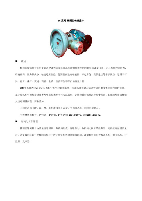
LC系列椭圆齿轮流量计■ 概述椭圆齿轮流量计是用于管道中液体流量连续或间断测量和控制的容积式计量仪表。
它具有量程范围大、准确度高、压力损失小、粘度适应性强、能测量高温高粘液体、标定方便、安装建议等诸多优点。
适用于石油、化工、化纤、交通、商贸、食品、医药卫生等部门的流量计量。
LCM型椭圆齿轮流量计装有指针和字轮累积装置,可现场直接显示流经管道内的液体流量和瞬时流量。
在计数机构中附加发讯装置与电显仪表配套可实现累积、定量和瞬时流量远传集中控制。
加装散热器或椭轮欠齿可测量高温、高粘液体。
不同的液体(酸、碱、盐、有机溶液等)流量计主体可选择不同的材质制造。
主体材质及代号:A-铸铁、E-铸钢、P-不锈钢 1Cr18Ni9Ti、1Cr18Ni12Mo2Ti。
■ 结构与工作原理椭圆齿轮流量计由流量变送器和计数机构组成。
变送器与计数机构之间加装散热器,则构成高温型流量计。
送变器由装有一对椭圆齿轮转子的计量室和密封联轴器组成,计数机构则包含减速机构、调节机构、计数器、发讯器。
计量室内由一对椭圆齿轮与盖板构成初月形空腔作为流量的计量单位。
椭圆齿轮靠流量计进出口压力差推动而旋转,从而不断地将液体经初月形空腔计量后送到出口处,每转流过的液体是初月形空腔的四倍,由密封联轴器将椭圆齿轮转的总数以及旋转的快慢传递给计数机构或发讯器,便可知道通过管道中液体总量和瞬时流量。
■主要技术参数准确度等级……………………0.2、0.5 流量范围………………………(见表1)允许基本误差(%)…….±0.2、±0.5 被测量液体温度(℃)公称通径DN(mm)……………….10~100 常温型: -10~+80公称压力PN(Mpa)高温型:+80~+200铸铁(A)、不锈钢(P)…1.0、1.6 被测液体粘度(mPa.s)…….0.3~200铸钢(E)……………2.5、4.0、6.3 管道连接法兰……………JB78~79~59表1 规格和流量范围■性能流量计的高精密度计量与底压力损失特性可由下面误差和压力损失曲线展示出来。
椭圆齿轮流量计的参数及安装

椭圆齿轮流量计的参数及安装
一、安装使用:
1、流量计前应安装过滤器,两者壳体上箭头指向与流动方向*。
2、当被测液体含有气体时,流量计前应安装气体分离器。
3、不论管路是垂直还是水平安装,但流量计中的椭圆齿轮轴安装成水平位置。
(即表度盘应与地面垂直)。
见图示。
4、流量计在正确安装情况下,如果不易看清读数,可把计数器转向180°或90°,均可。
5、新流量计在安装之前先用竹棍从出口处把齿轮推几次,如发现不动,可以用汽油浸泡(避免出厂校验后内存沉淀物)。
6、节流阀应安装在流量计进口处,开关阀安装在出口处,在开闭各阀门时要缓慢起动,不要急速开启或关闭阀门。
二.主要技术参数:
1.精度等级:普通型0.5级,高精度0.2级
2.介质压力:普通型1.6MPa,高压型
3.2MPa
3.粘度范围:普通型:0.6~200mpa.s,高粘度200~1000mpa.s
4.介质温度:普通型<120℃,高压型<200℃
5.表体材质:铸铁、不锈钢等
6.转动部件:铝合金、不锈钢等
7.本安防爆:ExiallAT3
8.连接方式:法兰连接DN10~DN100,螺纹连接DN10~DN50
9.安装方式;水平、垂直
10.口径系列:DN10,15,20,25,40,50,80,100
11.压力损失:≤0.1MPa
基本误差限(%)
公称压力(Mpa)
工作温度(℃)
液体粘度(mpa.s)
流量范围(m3/h)。
Fisherbrand FPDM1000系列机械椭圆齿流量计说明书
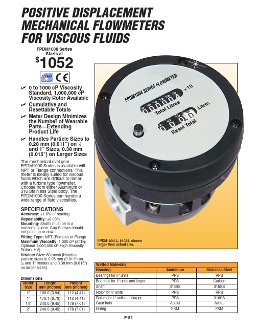
ߜ Meter Design Minimizes the Number of Wearable Parts—Extending Product Life
ߜ Handles Particle Sizes to 0.28 mm (0.011") on 1⁄2 and 1" Sizes, 0.38 mm (0.015") on Larger Sizes
Availability FPD1004, 1204 FPD1005, 1205 FPD1006, 1206 FPD1007, 1207 FPD1004, 1005, 1006, 1007, 1204 FPDM1205 FPDM1206 FPDM1207 FPDM1005, 1006, 1205, 1206 All models
FPDM1004-L, $1052, shown larger than actual size.
Wetted Materials Housing Bearings for 1⁄2" units Bearings for 1" units and larger Shaft Rotor for 1⁄2" units Rotors for 1" units and larger Gear train O-ring
1" Aluminum
2.2 (4.9) 80 (176)
34.5 (500)
1" Al w/ 150# Flange
3.1 (7.0) 80 (176) Flange Rule
1" SS
5.3 (11.7) 120 (248) 34.5 (500)
LC椭圆齿轮流量计使用说明书ZX
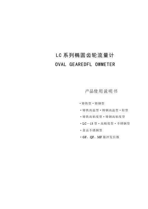
LC系列椭圆齿轮流量计OVAL GEAREDFL OWMETER产品使用说明书·铸铁型·铸钢型·铸铁高温型·铸钢高温型·轻型·铸铁高粘度型·铸钢高粘度型·LC—13型·高精度型·不锈钢型·食品不锈钢型·GF、QF、MF脉冲发信器LC系列椭圆齿轮流量计LC—AY40 LC—BH25 LC13—A25LC—AT40 LC—A50 LC12—A40一、概述椭圆齿轮流量计是用于管道中液体流量连续或间断测量和控制的容积式计量仪表。
它具有量程范围大、准确度高、压力损失小、粘度适应性强、能测量高温高粘液体、标定方便、安装建议等诸多优点。
适用于石油、化工、化纤、交通、商贸、食品、医药卫生等部门的流量计量。
LC系列椭圆齿轮流量计LC系列椭圆齿轮流量计装有指针和字轮累积装置,可现场直接显示流经管道内的液体流量和瞬时流量。
在计数机构中附加发讯装置与电显仪表配套可实现累积、定量和瞬时流量远传集中控制。
加装散热器或椭轮欠齿可测量高温、高粘液体。
不同的液体(酸、碱、盐、有机溶液等)流量计主体可选择不同的材质制造。
二、结构与工作原理椭圆齿轮流量计由流量变送器和计数机构组成。
变送器与计数机构之间加装散热器,则构成高温型流量计。
送变器由装有一对椭圆齿轮转子的计量室和密封联轴器组成,计数机构则包含减速机构、调节机构、计数器、发讯器。
计量室内由一对椭圆齿轮与盖板构成初月形空腔作为流量的计量单位。
椭圆齿轮靠流量计进出口压力差推动而旋转,从而不断地将液体经初月形空腔计量后送到出口处,每转流过的液体是初月形空腔的四倍,由密封联轴器将椭圆齿轮转的总数以及旋转的快慢传递给计数机构或发讯器,便可知道通过管道中液体总量和瞬时流量。
*如有特殊需要请另行注明三、性能(误差与压力损失曲线)解释:1 图中各种不同液体可用精度调节装置将流量计误差调整在0轴上下,使误差达最佳值。
椭圆齿轮流量计说明书

LC型椭圆齿轮流量计使用说明书目录一、概述 (1)二、技术性能特点 (1)三、工作原理 (2)四、连接方式 (3)五、调试与使用 (3)六、安装与使用注意 (5)七、型号表示方法 (6)八、开箱注意事项 (7)九、订货须知 (7)LC椭圆齿轮流量计一、概述我们具有独立的产品设计、制造体系,能够提供多种材料、口径和连接方式,还提供与之相配套的转换器、显示仪表和流量计算机等。
椭圆齿轮流量计的工作原理是液体推动一对椭圆齿轮转动;每个腔体的容积是固定体积;齿轮转速引出,传感器发出同步脉冲计数,椭圆齿轮的转动通过磁性密封联轴器及传动减速机构传递给计数器直接指示出流经流量计的总量。
若附加发信装置后,再配以电显示仪表,可实现远传只是瞬时流量和累积流量。
典型应用:椭圆齿轮流量计主要用于测量高粘度的介质,产品广泛应用于石油、石化、天然气、化工、造纸等行业,用于测量小管径的微小流量计量。
主要优点:◆口径从10~150mm;◆外壳材质有多种供选择:铝、不锈钢及中高压不锈钢、PPS、青铜等;◆轴承材质有多种供选择:陶瓷、青铜、哈氏合金、碳化物、PPS、不锈钢等;◆轴的材质:316不锈钢;◆ O形环的材质有VITON、氟橡胶、不锈钢、特氟隆供选择;◆量程比10:1,最大可达50:1;◆精度为±1%和±0.5%两种,重复性±0.03%;◆安装时直管段要求:5D+3D,需加装过滤器;◆粘度最高可达1,000 000CP;◆压力等级最高可达551bar;◆耐温等级最高可达-10~80℃;二、技术性能特点1. 椭圆齿轮流量计的技术性能型号 口径 最小流量 最大流量 精度等级工作压力(Mpa )LC —8 8 0.04 0.4 0.5,0.21.6,2.5,4.0,6.4LC —15 15 0.16 1.5 LC —20 20 0.3 3 LC —25 25 0.6 6 LC —40 40 1.5 15 LC —50 50 2.4 24 LC —80 80 6 60 LC —100 100 10 100 LC —150150121202.椭圆齿轮流量计的特点流量测量与流体的流动状态无关,这是因为椭圆齿轮流量计是依靠被测介质的压头推动椭圆齿轮旋转而进行计量的。
金湖奥科仪表有限公司

金湖奥科仪表有限公司椭圆齿轮流量计说明书AK-LC型椭圆齿轮流量计是一种容积型测量仪表,主要由计量壳体、椭圆齿轮转子和传动部件组成。
用于管道中液体流量连续或间断测量和控制的仪表。
它具有量程范围大、优异的准确度、压力损失小、粘度适应性强、能测量高温高粘液体、标定方便、安装简易等优点。
适用于原油、化工、化纤、交通、商贸、食品、医药卫生、科研和军事工业中流量的计量。
椭圆齿轮流量计可现场指示累积流量、瞬时流量,单次流量等,亦可输出脉冲信号、4-20mA或1-5V模拟信号、4-20mA+HART、MODBUS、支持232,485通讯等。
与中仪机械批控器或电子批控器组合,可实现不同型式的灌装,批控等多种功能。
三:特点流量计所有零件表面均经精密加工而成,无铸造表面,表面光洁美观。
流量计采用专利设计,无须专业人员即可现场拆卸再装,且再装后,不改变原有计量精度。
流量计采用防水设计。
流量计现场可显示累积流量、瞬时流量、单次流量等。
流量计执行标准:NIST(美国技术标准局专业标准)ZBN12001-87《容积式流量计通用技术条件》QB/SML01-2001《椭圆齿轮流量计》四:技术指标允许基本误差:±0.1% 、±0.2% 、±0.5%公称通径DN(mm):4~300公称压力PN(M.Pa):铸铁(A)、不锈钢(P)1 .0 、1.6、2.5、4.0、6.3铸钢(E)2.5、4.0、6.3 、9.6被测液体温度:低温型:-40~+60℃常温型-10℃~+80℃中温型-10℃~+200℃高温型-10℃~+300℃被测液体粘度(mPa.s):0.3~50000管道连接:GB/T9118-2000(中国标准法兰);NIST(美国标准法兰);BSPT(英国标准管螺纹):NPT(美国推拔管螺纹);现场显示:99999,999 L(累计流量)9999,999.9 L(单次流量)9999,999.9 L(瞬时流量)输出信号:脉冲信号、4~20mA、1-5V、4~20mA +HART协议、MODBUS支持RS232、RS485通讯(任选)防爆等级:EXiaIIBT5EXiaIICT5防护等级:IP65五:主要零件材料组合流量范围: 六、型号代码椭圆齿轮流量计(普通式)AK-LC系列轻型椭圆齿轮流量计,是我公司根据市场需要,研制成功的流量计。
椭圆齿轮流量计
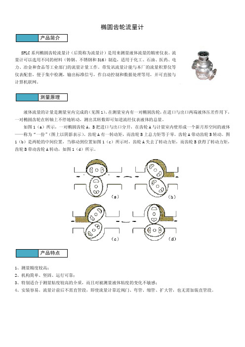
椭圆齿轮流量计SPLC系列椭圆齿轮流量计(后简称为流量计)是用来测量液体流量的精密仪表。
流量计可以选用不同的材料(铸钢、不锈钢和316)制造,适用于化工、石油、医药、电力、冶金和食品等工业部门的流量计量工作。
带发讯流量计能与本厂的流量积算仪等仪表配套,便于集中检测,输出标准信号,作自动控制和数据处理等用,并可直接与计算机联网。
液体流量的计量是测量室内完成的(见图1)。
在测量室内有一对椭圆齿轮,在进口与出口两端液体压差作用下,一对椭圆齿轮在转轴上不停地转动,测出其转数即可知道流经仪表液体的总量。
如图1(a)所示,一对椭圆齿轮A、B把进口与出口分开,在齿轮A与计量室内壁形成一个新月形空间的液体——称为“一份”(图上以阴影表示)。
齿轮A有一转动矩,而齿轮B上总力矩等于零。
齿轮A带动齿轮B转动。
图1(b)是两轮的中间位置,当移动到位置如图1(c)所示时,齿轮A失去了转动力矩,而齿轮B获得了转动力矩,齿轮B带动齿轮A转动,如图1(d)所示。
1、测量精度较高;2、机构简单、坚固、运行可靠;3、特别适合于测量粘度较高的介质,而且对被测量液体粘度的变化不敏感;4、安装容易。
流量计前后不需直管段,即使流量计靠近阀门、弯管、缩管、扩大管,也无需加装直管段。
连接法兰标准:JB/T 79-82-1994●铸钢形外形尺寸及重量单位:mm注:1.铸钢高温椭圆齿轮流量计外型尺寸:DN15-DN25,A、B尺寸接上表数据加160mm(热延伸管)其余尺寸同上表相应尺寸;DN40-DN200,A、B尺寸接上表尺寸加300mm(热延伸管)其余尺寸同上表相应尺寸。
2.表中所列数据为带A5(A6)计数器的基本型流量计的参考数据。
1、仪表安装的方向应使仪表壳体上所示箭头方向与液体流动方向一致,安装位置应注意便于读数。
2、仪表尽量安装在常温场合,不要安装在有害气体及强烈热辐射的场合,防止仪表计数器部分受损害。
3、仪表中的椭圆齿轮轴尽可能安装成水平位置,即刻度盘应安装成垂直位置(分度“0”应在上面),以减少椭圆齿轮与壳体之间的摩擦,降低零件的磨损。
HKLC 系列椭圆齿轮流量计使用说明书

使用说明HKLC系列椭圆齿轮流量计厦门宏控自动化仪表有限公司全国统一服务热线400-0592-364地址:厦门市湖里区双利工业园5号楼电话:************传真:************技术支持:153****2692(24小时)邮编:361015邮件:******************网址:目录一、概述.....................................................................................................................错误!未定义书签。
二、工作原理.............................................................................................................错误!未定义书签。
三、流量计结构 (3)四、主要技术数据 (4)五、发信器 (6)六、流量计外形尺寸 (7)七、安装与使用 (9)八、误差调整 (10)九、使用注意事项 (10)十、订货须知.............................................................................................................错误!未定义书签。
十一、常见故障原因、排除方法.............................................................................错误!未定义书签。
十二、流量计选型表.................................................................................................错误!未定义书签。
上海光华仪表 LCB型 椭圆齿轮流量变送器 说明书

LCB型椭圆齿轮流量变送器 (本质安全型 Ex ia Ⅱ CT5)使用说明书沪制02270188上海光华仪表有限公司上海光华仪表(厂)用户注意1. 本产品已通过ISO9001质量体系认证;2. 不锈钢变送器用于卫生、保洁场合时,请先用洗洁精和清水清洗;3.变送器安装前,应彻底清除管道内杂物和尘土,并加装过滤器;4.在安装使用前,必须详细阅读本使用说明书,用户应对不正确使用变送器而造成的损坏负责。
目录1.变送器外形和安装尺寸 (1)2.特点和适用范围 (1)3.型号规格和主要技术指标 (2)4.工作原理和结构 (3)5.防爆型变送器使用说明 (8)6.安装与使用 (8)7.调整 (11)8.故障的检查及排除 (13)9.运输和保管 (15)10.订货、退修须知 (15)附录过滤器外形及安装尺寸 (16)1. 变送器外形和安装尺寸图1-1 变送器外形尺寸型号 H L B Ø C n-d LCB-15□-B ~284 180~207 Ø15 Ø65 4-Ø14 LCB-20□-B ~290 200~207 Ø20 Ø75 4-Ø14 LCB-25□-B ~313 245~234 Ø25 Ø85 4-Ø14 LCB-40□-B ~343 250~234 Ø40 Ø1104-Ø18 LCB-50□-B ~365 346~278 Ø50 Ø1254-Ø18 LCB-80□-B ~392 370~278 Ø80 Ø1608-Ø182. 特点和适用范围LCB-□□-B型椭圆齿轮流量变送器,在防爆场合与LB960安全栅配套,在非防爆场合也可与适宜的其他型号流量显示仪表配套,组成椭圆齿轮流量计。
它是一种计量流经管道内液体流量总量的容积式仪表,具有远距离显示和现场读取累计流量,可与大多数调节系统组合,实现流量检测和控制的自动化。
椭圆齿轮流量计电子型号025 1英寸CR型说明书

INSTRUCTION MANUALTo the OwnerOVAL GEAR FLOWMETER ELECTRONIC MODEL 025 / 1”Type ‘CR’ for Corrosive ApplicationsPLEASE READ THIS SAFTEY INFORMATION CAREFULLY BEFORE USE.Read and retain this instruction manual to assist you in the operation and maintenance of this product.If you have any problems with the meter, refer to the maintenance and trouble shooting sections of this manual.This manual contains connection and operating in-structions for meters with Pulse outputs.Models with a Liquid Crystal Display have an addi-tional LCD instruction manual supplied. If you need further assistance, contact your local representative or distributor for advice.This Flow Meter has incorporated the oval rotor prin-cipal into its design. This has proven to be a reliable and highly accurate method of measuring flow.Exceptional repeatability and high accuracy over a wide range of fluid viscosities and flow rates are features of the oval rotor design. With a low pressure drop and high pressure rating oval rotor flow meters are suitable for both gravity and pump (in line) applications.This instruction manual covers pulse meters con-structed in Aluminium or Stainless Steel. Also in-cluded are the high pressure versions of this model.WARNINGBefore use, confirm the fluid to be used is com-patible with the meter. Refer to Industry fluid compatibility charts or consult your local rep-resentative for advice.To prevent damage from dirt or foreign matter it is recommended that a Y or Basket type 60 mesh strainer be installed as close as possible to the inlet side of the meter. Contact your local repre-sentative for advice.When a strainer is installed it should be regularly inspected and cleaned. Failure to keep the strainer clean will dramatically effect flow meter performance.To prevent damage caused by air purge slowly fill the meter with fluid. To reduce pressure build up turn off the pump at the end of each day.Maintenance can be carried out to the liquid crystal displays and pulse units without removing or isolat-ing the meter from the line. When maintenance to any other part of the meter is required, the meter must be isolated and the line pressure reduced.The reed switch pulse unit can cause inaccurate rate counts when used with high speed counters. It is advised that a debounce circuit be used. Contact your meter distributor for further information.CAUTIONCAUTION When fluid passes through the meter the rotors turn, as shown below. The magnets which are located in the rotors will pass across the pulsercircuit board (containing either Reed switches or Hall Effect sensors). A signal is generated which is then sent by the Pulse Circuit Board (PCB) to the relevantLC display or receiving instrument..1) It is recommended that when setting up pipe work for meter installations a bypass line be included in the design. This provides the facility for a meter to be removed for maintenance without interrupting production. (see figure above)2) Use thread sealant on all pipe threads.3) For pump applications ensure pipe work has the appropriate working pressure rating to match the pressure output of the pump. See Meter Specifications section for further details.4) Install a wire mesh strainer, Y or basket type60 mesh (250 micron), as close as possible to the inlet side of the meter.5) Ensure that the meter is installed so that the flow of the liquid is in the direction of the arrows embossed on the meter body.6) The meter can be installed in any orientation as long as the meter shafts are in a horizontal plane. (Refer to figures to the right for correct installation) The register assembly may be orientated to suit the individual.Note: Incorrect installation can cause premature wear of meter components.7) Do not over tighten meter connections. Note:Incorrect installation can cause premature wear of meter components.8) It is important that after initial installation you fill the line slowly, high speed air purge could cause damage to the rotors.9) Test the system for leaks.10) Check the strainer for swarf or foreign material, after the first 200 litres check periodically,particularly if the flow rate decreases.Ensure that the fluid supply to the meter is dis-connected, and the line pressure is released be-fore disassembly, with the exception for repair or maintenance to the LC Display or PCB where there is no necessity to isolate the meter from flow. Refer to the exploded parts diagram on subsequent pages for item numbers.1) Pulse Caps Models: Undo the conduit connector, remove pulse cap (item 9) and remove the wires from the pulse terminal board (item 5).2) Standard LC Display: Mark the display orientation with a marking pen, unscrew the four large screws on top of the LC Display. Carefully separate the LC Display from the plastic housing and disconnect the wires from the pulse terminalblock. (Refer to additional LCD instruction manual accompanying these instructions). Remove the mounting adaptor plate and gasket.3) Loosen the cap head screws (Item 7) that hold down the meter cap (Item 4), remove the screws, washers and lift off the cap.4) Remove the o-ring (Assembly Item 2) from the o- ring groove in the meter cap (Assembly Item 4).5) Remove rotors (Item 3).1) Before reassembling check the condition of therotors (replace if necessary).2) Check that the smooth side of the rotors (not the plug side) is facing you when inserting the rotors, the smooth side of the rotor is the magnet side. There is no difference between rotor one or rotor two.3) Replace the rotors (Item 3) onto the shafts at 90 degrees to each other (refer Fig) and check their operation by turning either of the rotors.If the rotors are not in mesh correctly or do not move freely, remove one of the rotors and replace correctly at 90 degrees to the other rotor.4) Re-check the operation of the rotors5) Replace the o’ring (Item 2) into groove in the meter cap, if the o’ring has grown or is damaged in any way replace it with a new part.6) Replace the meter cap making sure that the locating pin in the body lines up with the hole in the meter cap.7) Insert the cap head screws (Item 7) and tighten i n a diagonal sequence 1, 3, 2, 4, etc.8) The replacement of cables and connectors are a reversal of the disassembly procedure, replace conduit fitting if required.When replacing the Standard LC Display confirm the orientation marks made on disassembly are aligned then screw the register into place.9) Test the meter by turning the rotors with a finger or by applying very low air pressure (no more than a good breath) to one end of the meter, before returning t he meter to the line.1. Conforms to Directive 97/23/EC—Cat 1Pulser Board/Sensor SpecificationsThere are 2 pulse board options with all Macnaught pulse flowmeters:Standard Option 1 - 1x Reed Switch 1x Hall Effect OutputHazardous Option 2 - 2x Reed Switch Output2. Voltage & current specifications apply per sensor (not combined).3. Contact rating maximum is 10W. Neither current nor voltage maximums should be exceeded in achieving this.Analogue Output (4-20mA)Analogue outputs are available as an auxilliary display signal by including either of the following LCD displays with your flow-meter. These may be fitted to the meter or remote (wall mount) types.DRA Small display with analogue output moduleERA Large display with analogue output moduleNote: Consult the following instruction sheets if the flow meter is fitted with an LCD Display. Display Part Number: DRDRAER ERB ERAERSInstruction Sheet:DR013 DR014 MS574 MS392 MS476MS351Reed Switch 1Reed Switch 2Reed Switch Hall Effect* Macnaught pulser boards are not fitted with a pull up resistor. Consult sensor specifications on page 4 for selection of appropriate resistance.Pull up Res Ω*Note: Reed Switches are not polarity sensitive.Please read this information carefully before installationHall Effect:Hall effect sensors require an external pull up resistor to be fitted by the installer for correct operation. Powering a Hall effect sensor without a resistor wired between the supply voltage and the signal line will result in damage to the sensor. Reed Switch:In order to protect the reed switch from over current, and to maximise life expectancy, we recommend limiting the current through the switch by fitting a series resistor in between the signal leg and the PLC/signal sensing device.V1+ V1-GNDSIG2 VccV1+V1-V2+V2-NOT USEDStandard. Option 1Hazardous. Option 2Series Res Ω**** Macnaught pulser boards are not fitted with a current limiting resistor. For 12VDC we recommend a1k Ω resistor . For 24VDC, we recommend a 1.8k-2.2k Ω resistor.123 4 5Series Res Ω**Series Res Ω**1 2 3 45Parts IdentificationCoding SequenceCustomer Model NumberThere are 4 Spare Kit options available for the purchase of replacement components:∙ Pulser Kit (PKit) - Replacement PCB. ∙ Rotor Kit (RKit) - Complete Rotor assembly ∙ Seal Kit (SKit) - Complete set of O-Rings/GasketsSpare Kit Coding Procedure.1. Determine what type of Spare Parts Kit is required (e.g. Rotor Kit)2. Use the ‘Coding Sequence’ to construct a part number according to the meter type.Customer Model NumberRotor Kit - (R Kit)Customer Model NumberKit ComponentsKit ComponentsPPS - Polyphenylene SulphidePVDF - Polyvinylidene FlouridePTFE - PolytetrafluoroethyleneHast C - Hastelloy C ™K - FEP/PTFE Encapsulated100%50%The WEEE Directive requires the recycling of waste electrical and electronic equip-ment in the European Union.Whilst the WEEE Directive does not apply to some of Macnaught’s products, we sup-port its policy and ask you to be aware of how to dispose of this product.The crossed out wheelie bin symbol illustrated and found on our products signifies that this product should not be disposed of in general waste or landfill.Please contact your local dealer national distributor or Macnaught Technical Servicesfor information on product disposal.。
椭圆齿轮流量计说明书样本

一、用途:椭圆齿轮流量计是一种指针显示, 字轮累积计数装置及回零装置的轻型容积式流量仪表, 广泛应用于各工业领域的液体流量控制, 适用于各种类型的液体测量, 如原油、柴油、汽油等, 具有量程大, 精度高, 使用和维修方便等特点, 选用不同的制造材料, 可满足石油、化工、医药、食品、冶金、电力、交通等各领域的液体流量计量。
二、工作原理与结构:流量计是由计量箱和装在计量箱内的一对椭圆齿轮, 与上下盖板构成一个密封的初月形空腔( 由于齿轮的转动, 因此不是绝对密封的) 作为一次排量的计算单位。
当被测液体经管道进入流量计时, 由于进出口处产生的压力差推动一对齿轮连续旋转, 不断地把经初月形空腔计量后的液体输送到出口处, 椭圆齿轮的转数与每次排量四倍的乘积即为被测液体流量的总量( 原理见图1) 。
流量计主要是由壳体、计数器、椭圆齿轮和联轴器( 分磁性联轴器和轴向联轴器) 等组成( 结构见图2) 。
图1 椭圆齿轮运转原理图( 图2) 椭圆齿轮流量计结构图1、计数器 2发信器 3、精度调节器( DN50以上使用) 4、密封联轴器 5、前盖 6、盖板 7、椭圆齿轮8、壳体 9、后盖三、技术数据:(一)普通铸铁型(A)、铸钢型(E)、不锈钢型(B)椭圆齿轮流量计(二) 高温铸铁型(TA)、铸钢型(TE)、不锈钢型(TB)椭圆齿轮流量计(三)高粘度铸铁型(NA)、铸钢型(NE)椭圆齿轮流量计四、 LC-13型椭圆齿轮流量变送器LC-13型椭圆齿轮流量变送器是由本体和QF13型发信器组成, 可将管到内液体流量转换为电脉冲信号输出。
她与我厂生产的EL系列显示仪表配套使用( 可与能接受该信号的其它仪表, 如微机、显示仪表配套) 。
经过电子仪表直接显示流经管道中液体总量及瞬时流量, 适宜于远距离显示, 自控调节、电脑加油等场合。
1、技术性能1) 允许基本误差: ±0.2%2) 被测液体粘度: 0.6~200mpa.s3) 被测液体温度: -10~+65℃4) 最大工作压力铸铁、不锈钢1.6Mpa铸钢: DN20~25, 2.5Mpa, DN~15,DN40,6.4Mpa5) 主要材质: 铸铁、铸钢、不锈钢6) 管道连接法兰: JB78-59, JB79-597) 发信装置: QF13发信器a、供电: 12VDC( 我厂显示仪表中已配)b、脉冲幅度V=4V( 方波) 低电平<4.5V,高电平>8.5Vc、传输距离: 1Km( 金属屏蔽线导线电阻≤39Ω)8) 电性能精度: ±1个脉冲9) 防爆等级: IAⅡCT510) 防爆安全栅型号: NF713五、 QF发信器在本厂生产带A1、 E1+T计数器的椭圆齿轮流量计上( 或变送器上) 安装发信器, 即可远传发信, 它将被测介质的流量转换成电脉冲信号, 从而实现系统自动控制。
椭圆齿轮流量计

一、椭圆齿轮流量计的工作原理
一、椭圆齿轮流量计的工作原理
远传显示主要是通过减速后的齿轮 带动永久磁铁旋转,使得弹簧继电器 的触点以与永久磁铁相同的旋转频率 同步地闭合或断开,从而发出一个个 电脉冲远传给另一显示仪表.
椭圆齿轮流量计
二、椭圆齿轮流量计的优点 椭圆齿轮流量计的优点
椭圆齿轮流量计计量精度高 计量精度高, 1、椭圆齿轮流量计计量精度高, 基本误差一般为±0.5% 基本误差一般为±0.5%R,特殊的可 0.2% 或更高。 达±0.2%R或更高。通常在昂贵介质 或需要精确计量的场合使用。 或需要精确计量的场合使用。
二、椭圆齿轮流量计的优点 椭圆齿轮流量计的优点
椭圆齿轮流量计是直读式仪表, 5、椭圆齿轮流量计是直读式仪表, 无需外部能源, 无需外部能源,可直接获得累计总 清晰明了,操作简便。 量,清晰明了,操作简便。
三构复杂, 1、椭圆齿轮流量计结构复杂,体 积大,笨重, 积大,笨重,尤其较大口径椭圆齿 轮流量计体积庞大, 轮流量计体积庞大,故一般只适用 于中小口径。 于中小口径。 被测介质种类、介质工况( 2、被测介质种类、介质工况(温 压力)、口径局限性较大, )、口径局限性较大 度、压力)、口径局限性较大,适应 范围窄。 范围窄。
椭圆齿轮流量计
李桂红
辽化仪表厂
椭圆齿轮流量计是容积式流量计 的一种, 的一种,是在流量仪表中精度最高 的一类, 的一类,用于精密的连续或间断的测 量管道中液体的流量或瞬时量. 量管道中液体的流量或瞬时量.它 特别适合于重油、聚乙烯醇、 特别适合于重油、聚乙烯醇、树脂 等粘度较高介质的流量测量。 等粘度较高介质的流量测量。
四、椭圆齿轮流量计的安装 椭圆齿轮流量计的安装
1、椭圆齿轮流量计在安装前应清洁 管道.若液体内含有固体颗粒, 管道.若液体内含有固体颗粒,则必 须在管道上游加装过滤器; 须在管道上游加装过滤器;若含气体 应安装排气装置。 应安装排气装置。 2、椭圆齿轮流量计对前后直管段没 有一定的要求。 有一定的要求。它可以水平或垂直安 安装时, 装。安装时,应使流量计的椭圆齿轮 转动轴与地面平行。 转动轴与地面平行。
Omega FPD3100系列1 4英寸-1英寸椭圆齿轮流量计用户指南说明书
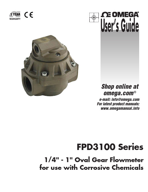
e-mail:**************For latest product manuals: FPD3100 S eries1/4" - 1" Oval Gear Flowmeter for use with CorrosiveChemicalsShop online at ®User’s Guide***********************Servicing North America:U.S.A.:Omega Engineering, Inc., One Omega Drive, P.O. Box 4047S tamford, CT 06907-0047 USAToll-Free: 1-800-826-6342 (USA & Canada only)Customer Service: 1-800-622-2378 (USA & Canada only)Engineering Service: 1-800-872-9436 (USA & Canada only)Tel: (203) 359-1660 Fax: (203) 359-7700e-mail:**************For Other Locations Visit /worldwideThe information contained in this document is believed to be correct, but OMEGA accepts no liability for any errors it contains, and reserves the right to alter specifications without notice.WARNING: These products are not designed for use in, and should not be used for, human applications.InstallationPre-installation checks Page 4 …………………………………………………………. Operating Principle Page 5 …………………………………………………………. Installation ProcedurePage 5………………………………………………………….Maintenance ProcedureDisassembly Page 6 …………………………………………………………. ReassemblyPage 6………………………………………………………….Flowmeter SpecificationsFlowmeter Specifications Page 7 …………………………………………………………. Electrical SpecificationsPage 8………………………………………………………….ServiceDigital Displays Page 9 …………………………………………………………. Exploded Diagram Page 10-11 …………………………………………………………. Spare Parts Kits Page 12 …………………………………………………………. Wetted PartsPage 12………………………………………………………….GeneralPressure Drop Graphs Page 13 …………………………………………………………. Dimensional DiagramsPage 14-15………………………………………………………….Troubleshooting Guide Page 9 ………………………………………………………….Please read and retain this instruction manual to assist you in the operation and maintenance of this product.This manual contains connection and operating instructions for the FPD Flowmeter series with Pulse outputs.Models with a Liquid Crystal Display have an additional LCD instruction manual supplied. If you need further assistance, contact your local representative or distributor for advice.This Flow Meter has incorporated the oval rotor principal into its design. This is proven to be a reliable and highly accurate method of measuring flow.Exceptional repeatability and high accuracy over a wide range of fluid viscosities and flow rates are features of the oval rotor design.With a low pressure drop and high pressure rating oval rotor flow meters are suitable for both gravity and (in-line) pump applications.FLUID COMPATABILITYBefore use, confirm the fluid to be used is compatible with the meter. Refer to Industry fluid compatibility charts or consult your local represen-tative for advice.AIR PURGE / LINE PRESSUREREED SWITCHTo prevent damage caused by air purge slowly fill the meter with fluid.To reduce pressure build-up turn off theat the end of each day.The reed switch can cause inaccurate rate counts when used with high speed counters.It is advised that a low speed counter is used or alternatively a denounce circuit be installed.STRAINERTo prevent damage from dirt or foreign matter it is recommended that a Y or Basket type mesh strainer be installed as close aspossible to the inlet side of the me-ter.When a strainer is installed it should be regularly inspected and cleaned. Failure to keep the strainer clean will dramatically effect flow me-ter performance.Contact your local representative for ad-vice.INSTALLATION PROCEDUREFluid passing through the meter causes the rotors to turn, as shown below.One of the rotors (the active rotor) is fitted with magnets.The passing of the magnets are picked up by the sensing elements (Reed and Hall Effect sensors) located in the Pulser Circuit Board.The excitation of these switches provides a ‘Raw Pulse Output’ which relates to the K -Factor. (e.g. KF 36 = 36 pulses per litre of fluid passed ) This Pulse Output Signal can either be fed directly to an external receiving element (e.g. Data Logger or PLC) or alternatively to an LC Display which condi-tions the Pulse input signal to display volume of fluid passed. (e.g. Display 1 Litre per for every 36 pulses received)1.It is recommended that when setting up pipe work for meter installations, a bypass line be included in the design. This provides the facility for a meter to be removed for maintenance without interrupt ing production. (see figure above )e thread sealant on all pipe threads.3.For pump applications ensure pipe work and Meter have the appropriate working pressure rating to match the pressure output of the pump.Refer to Meter Specifications section for further details.4.Install a wire mesh strainer, Y or basket type as close as possible to the inlet side of the meter.Meter 1/4” 74 micron / 200 mesh Meter 1”250 micron / 60 mesh5.Note: The Flowmeter can accept flow in any direction.6.The meter can be installed in any orientation as long as the meter shafts are in a horizontal plane.(Refer to diagram below for correct installation).Note: Incorrect installation can cause premature wear of meter components.The LC display may removed by loosening the 4 mounting screws and be orientated as required. 7.Do not over tighten meter connections. .8.It is important that after initial installation you fill the line slowly, high speed air purge could cause damage to the rotors.9.Test the system for leaks.10.Check the strainer for swarf or foreign material,after the first 200 litres check periodically,particularly if the flow rate is noted to be decreasing.Ensure that the fluid supply to the meter is dis-connected, and the line pressure is released be-fore disassembly, with the exception for repair or maintenance to the LC Display or PCB where there is no necessity to isolate the meter from flow. Refer to the exploded parts diagram on subsequent pages for item numbers.1) Pulse Caps Models: Undo the conduit connector, remove pulse cap (item 9) and remove the wires from the pulse terminal board (item 5).2) Standard LC Display: Mark the display orientation with a marking pen, unscrew the four large screws on top of the LC Display. Carefully separate the LC Display from the plastic housing and disconnect the wires from the pulse terminalblock. (Refer to additional LCD instruction manual accompanying these instructions). Remove the mounting adaptor plate and gasket.3) Loosen the cap head screws (Item 7) that hold down the meter cap (Item 4), remove the screws, washers and lift off the cap.4) Remove the o-ring (Assembly Item 2) from the o- ring groove in the meter cap (Assembly Item 4).5) Remove rotors (Item 3).1) Before reassembling check the condition of therotors (replace if necessary).2) Check that the smooth side of the rotors (not the plug side) is facing you when inserting the rotors, the smooth side of the rotor is the magnet side. There is no difference between rotor one or rotor two.3) Replace the rotors (Item 3) onto the shafts at 90 degrees to each other (refer Fig) and check their operation by turning either of the rotors.If the rotors are not in mesh correctly or do not move freely, remove one of the rotors and replace correctly at 90 degrees to the other rotor.4) Re-check the operation of the rotors5) Replace the o’ring (Item 2) into groove in the meter cap, if the o’ring has grown or is damaged in any way replace it with a new part.6) Replace the meter cap making sure that the locating pin in the body lines up with the hole in the meter cap.7) Insert the cap head screws (Item 7) and tighten i n a diagonal sequence 1, 3, 2, 4, etc.8) The replacement of cables and connectors are a reversal of the disassembly procedure, replace conduit fitting if required.When replacing the Standard LC Display confirm the orientation marks made on disassembly are aligned then screw the register into place.9) Test the meter by turning the rotors with a finger or by applying very low air pressure (no more than a good breath) to one end of the meter, before returning t he meter to the line.Pulser Board/Sensor SpecificationsThere are two sensors on each PCB 1x Reed Switch 1x Hall Effect Output2. Voltage & current specifications apply per sensor (not combined).3. Contact rating maximum is 10W. Neither current nor voltage maximums should be exceeded in achieving this.WIRING DIAGRAMPlease read this information carefully before installationHall Effect:Hall effect sensors require an external pull up resistor to be fitted by the installer for correct operation. Powering a Hall effect sensor without a resistor wired between the supply voltage and the signal line will result in damage to the sensor. Reed Switch:In order to protect the reed switch from over current, and to maximise life expectancy, we recommend limiting the current through the switch by fitting a series resistor in between the signal leg and the PLC/signal sensing device.Series Res Ω**HEDIGITAL DISPLAYSThe Flow meter series is supplied with either a Blind Pulser and Digital Display option.If the Flow meter is supplied with an LC Display fitted, please consult the appropriate Instruction Manual, as advised below, for all programming and wiring instructions.Analog Output (4-20mA)Analog outputs are available as an auxiliary display signal by including either of the following LC displays with your flowmeter. These may be fitted to the meter or remote (wall mount) types.FPD3100-D 12mm LC Display (No output options)FPD3100-D-A 12mm LC Display with analog output moduleTroubleshooting GuidePARTS IDENTIFICATIONThere are 4 Spare Kit options available for the purchase of replacement components: ∙Pulser Kit(PKit) -Replacement PCB.∙Rotor Kit(RKit) -Complete Rotor assembly∙Seal Kit(SKit) -Complete set of O-Rings/GasketsWETTED PARTSK - FEP/PTFE EncapsulatedFFKM - PerfluoroelastomerPPS - Polyphenylene Sulphide (PPS Resin)Digital Display Type -D or -D-A PulserDigital Display Type -D or -D-APulserWARRANTY/DISCLAIMEROMEGA ENGINEERING, INC. warrants this unit to be free of defects in materials and workmanship for a period of 13 months from date of purchase. OMEGA’s WARRANTY adds an additional one (1) month grace period to the normal one (1) year product warranty to cover handling and shipping time. This ensures that OMEGA’s customers receive maximum coverage on each product.If the unit malfunctions, it must be returned to the factory for evaluation. OMEGA’s Customer Service Department will issue an Authorized Return (AR) number immediately upon phone or written request. Upon examination by OMEGA, if the unit is found to be defective, it will be repaired or replaced at no charge. OMEGA’s WARRANTY does not apply to defects resulting from any action of the purchaser, including but not limited to mishandling, improper interfacing, operation outside of design limits, improper repair, or unauthorized modification. This WARRANTY is VOID if the unit shows evidence of having been tampered with or shows evidence of having been damaged as a result of excessive corrosion; or current, heat, moisture or vibration; improper specification; misapplication; misuse or other operating conditions outside of OMEGA’s control. Components in which wear is not warranted, include but are not limited to contact points, fuses, and triacs.OMEGA is pleased to offer suggestions on the use of its various products. However, OMEGA neither assumes responsibility for any omissions or errors nor assumes liability for any damages that result from the use of its products in accordance with information provided by OMEGA, either verbal or written. OMEGA warrants only that the parts manufactured by the company will be as specified and free of defects. OMEGA MAKES NO OTHER WARRANTIES OR REPRESENTATIONS OF ANY KIND WHATSOEVER, EXPRESSED OR IMPLIED, EXCEPT THAT OF TITLE, AND ALL IMPLIED W ARRANTIES INCLUDING ANY W ARRANTY OF MERCHANTABILITY AND FITNESS FOR A PARTICULAR PURPOSE ARE HEREBY DISCLAIMED. LIMITATION OF LIABILITY: The remedies of purchaser set forth herein are exclusive, and the total liability of OMEGA with respect to this order, whether based on contract, warranty, negligence, indemnification, strict liability or otherwise, shall not exceed the purchase price of the component upon which liability is based. In no event shall OMEGA be liable for consequential, incidental or special damages.CONDITIONS: Equipment sold by OMEGA is not intended to be used, nor shall it be used: (1) as a “Basic Component” under 10 CFR 21 (NRC), used in or with any nuclear installation or activity; or (2) in medical applications or used on humans. Should any Product(s) be used in or with any nuclear installation or activity, medical application, used on humans, or misused in any way, OMEGA assumes no responsibility as set forth in our basic WARRANTY /DISCLAIMER language, and, additionally, purchaser will indemnify OMEGA and hold OMEGA harmless from any liability or damage whatsoever arising out of the use of the Product(s) in such a manner.OMEGA’s policy is to make running changes, not model changes, whenever an improvement is possible. This affords our customers the latest in technology and engineering.OMEGA is a registered trademark of OMEGA ENGINEERING, INC.© Copyright 2013 OMEGA ENGINEERING, INC. All rights reserved. This document may not be copied, photocopied, reproduced, translated, or reduced to any electronic medium or machine-readable form, in whole or in part, without the prior written consent of OMEGA ENGINEERING, INC.FOR WARRANTY RETURNS, please have the following information available BEFORE contacting OMEGA:1. P urchase Order number under which the product was PURCHASED,2. M odel and serial number of the product under warranty, and3.Repair instructions and/or specific problems relative to the product.FOR NON-WARRANTY REPAIRS, consult OMEGA for current repair charges. Have the followinginformation available BEFORE contacting OMEGA:1.Purchase Order number to cover the COST of the repair,2.Model and serial number of the product, and3.Repair instructions and/or specific problems relative to the product.RETURN REQUESTS/INQUIRIESDirect all warranty and repair requests/inquiries to the OMEGA Customer Service Department. BEFORE RETU RNING ANY PRODU CT(S) TO OMEGA, PU RCHASER MU ST OBTAIN AN AU THORIZED RETU RN (AR) NU MBER FROM OMEGA’S CU STOMER SERVICE DEPARTMENT (IN ORDER TO AVOID PROCESSING DELAYS). The assigned AR number should then be marked on the outside of the return package and on any correspondence.The purchaser is responsible for shipping charges, freight, insurance and proper packaging to prevent breakage in transit.Where Do I Find Everything I Need for Process Measurement and Control?OMEGA…Of Course!Shop online at SMTEMPERATUREM U Thermocouple, RTD & Thermistor Probes, Connectors, Panels & AssembliesM U Wire: Thermocouple, RTD & ThermistorM U Calibrators & Ice Point ReferencesM U Recorders, Controllers & Process MonitorsM U Infrared PyrometersPRESSURE, STRAIN AND FORCEM U Transducers & Strain GagesM U Load Cells & Pressure GagesM U Displacement TransducersM U Instrumentation & AccessoriesFLOW/LEVELM U Rotameters, Gas Mass Flowmeters & Flow ComputersM U Air Velocity IndicatorsM U Turbine/Paddlewheel SystemsM U Totalizers & Batch ControllerspH/CONDUCTIVITYM U pH Electrodes, Testers & AccessoriesM U Benchtop/Laboratory MetersM U Controllers, Calibrators, Simulators & PumpsM U Industrial pH & Conductivity EquipmentDATA ACQUISITIONM U Data Acquisition & Engineering SoftwareM U Communications-Based Acquisition SystemsM U Plug-in Cards for Apple, IBM & CompatiblesM U Data Logging SystemsM U Recorders, Printers & PlottersHEATERSM U Heating CableM U Cartridge & Strip HeatersM U Immersion & Band HeatersM U Flexible HeatersM U Laboratory HeatersENVIRONMENTALMONITORING AND CONTROLM U Metering & Control InstrumentationM U RefractometersM U Pumps & TubingM U Air, Soil & Water MonitorsM U Industrial Water & Wastewater TreatmentM U pH, Conductivity & Dissolved Oxygen InstrumentsM-5425/0816。
电子椭圆齿轮流量计使用说明书2
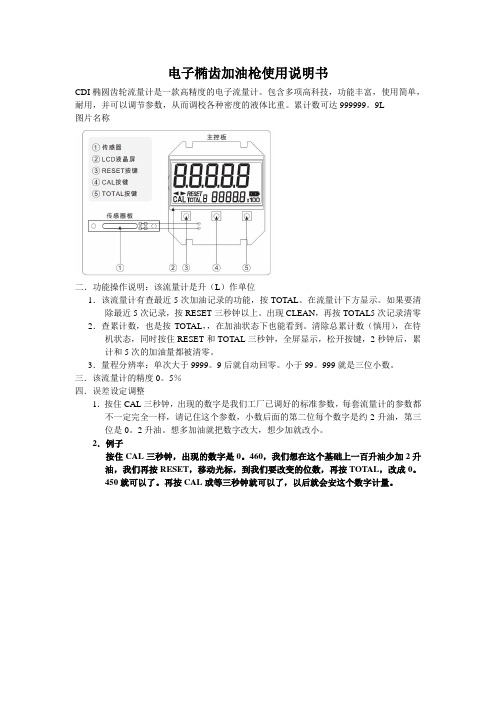
电子椭齿加油枪使用说明书
CDI椭圆齿轮流量计是一款高精度的电子流量计。
包含多项高科技,功能丰富,使用简单,耐用,并可以调节参数,从而调校各种密度的液体比重。
累计数可达999999。
9L
图片名称
二.功能操作说明:该流量计是升(L)作单位
1.该流量计有查最近5次加油记录的功能,按TOTAL。
在流量计下方显示。
如果要清除最近5次记录,按RESET三秒钟以上。
出现CLEAN,再按TOTAL5次记录清零2.查累计数,也是按TOTAL,,在加油状态下也能看到。
清除总累计数(慎用),在待机状态,同时按住RESET和TOTAL三秒钟,全屏显示,松开按键,2秒钟后,累计和5次的加油量都被清零。
3.量程分辨率:单次大于9999。
9后就自动回零。
小于99。
999就是三位小数。
三.该流量计的精度0。
5%
四.误差设定调整
1.按住CAL三秒钟,出现的数字是我们工厂已调好的标准参数,每套流量计的参数都不一定完全一样,请记住这个参数,小数后面的第二位每个数字是约2升油,第三位是0。
2升油。
想多加油就把数字改大,想少加就改小。
2.例子
按住CAL三秒钟,出现的数字是0。
460,我们想在这个基础上一百升油少加2升油,我们再按RESET,移动光标,到我们要改变的位数,再按TOTAL,改成0。
450就可以了。
再按CAL或等三秒钟就可以了,以后就会安这个数字计量。
LC 系列椭圆齿轮流量计使用说明书

LC系列椭圆齿轮流量计使用说明书TYPE LCOVAL FLOWMETERINSTRUCTION MANUAL合肥精大仪表股份有限公司(原合肥仪表总厂)HEFEI JINGDA INSTRUMENT CO.,LTD (HEFEI INSTRUMENT GENERAL FACTORY)一、概述椭圆齿轮流量计是用于对管道中液体流量进行连续测量的高精度计量仪表。
它具有量程范围大、压力损失小、粘度适应性强,能测量高温、高粘度液体、标定方便、安装简易等诸多优点,是容积式流量计的代表产品。
LC 系列椭圆齿轮流量计,装有现场指针显示、字轮累计计数装置,可以直接显示流经管道内的液体累积流量。
对不同的液体(酸、碱、盐、有机溶液等)流量计可以选择不同的材质(铸铁、铸钢、铝合金、不锈钢等)制成。
适用于石油、化工、化纤、交通、商业、食品、医药卫生等工业部门的流量计量。
二、原理结构椭圆齿轮流量计由流量变送器和计数机构组成。
变送器的主要部分是由装有一对椭圆齿轮转子的计量室和密封联轴器组成。
计数机构则包含减速机构、精度调节机构,计数器和电脉冲发信器等部件。
计量室内主要有一对椭圆齿轮与盖板构成初月形空腔作为流量的计量单位。
椭圆齿轮靠流量计进出口处的压力差推动而旋转,从而不断地把进口处的液体经初月形空腔计量后送到出口处,每转流过的液体量是图中新月腔的四倍,由密封联轴器将椭圆齿轮旋转的总数,以及旋转的快慢传递给计数机构,通过指针显示和字轮累积,即可知道通过管道中的液体总量。
在计数机构中还可安装脉冲发信器即成了带发信的椭圆齿轮流量计,与本公司电显示仪表配套,可以实现远传(定量、累积、瞬时等功能)自动化测量和控制。
使用说明另见显示仪表分类说明。
1、计数器2、发信器3、精度调节器4、密封联轴器5、前盖6、盖板7、椭圆齿轮8、壳体 9、后盖三、通用技术参数1. 主要构件材料及公称压力壳体、前盖后盖盖板椭圆齿轮轴轴套公称压力(MPa )LC-A 铸铁 铸铁 1.6LC-E 铸钢 铸铁 含油青铜 或滚动轴承 DN50以下 6.3; DN80-1004.0 、6.3; DN150-200 2.5。
ULTRA OVAL 椭圆齿轮流量计操作说明书 (中文版)

6.1 安装时的考虑事项.................................................................................................................10 6.2 标准安装,水平线.............................................................................................................10 6.3 标准安装,垂直线.............................................................................................................10 6.4 错误管线示例.....................................................................................................................10 7.如何改变流向.........................................................................................................................11 8.接线说明.................................................................................................................................12 8.1 接线指导.............................................................................................................................12 8.2 端接.....................................................................................................................................12 8.3 连接图.................................................................................................................................13 8.4 关于负载阻值范围.............................................................................................................13 9.操作说明.................................................................................................................................14 9.1 操作.....................................................................................................................................14 9.2 操作预防事项.....................................................................................................................15 9.3 有关操作停工的预防事项.................................................................................................16 9.4 关于计数器的使用寿命.....................................................................................................16 9.5 关于仪表系数.....................................................................................................................17 10.拆卸与检查...........................................................................................................................17 10.1 型号 39,41,45,50 基本仪表拆卸与检查 .................................................................17 10.2 型号 39,41,45,50 基本仪表组装程序 .....................................................................18 10.3 型号 52,53,55,56,57 仪表本体拆卸与检查 .........................................................19 10.4 型号 52,53,55,56,57 基本仪表组装程序 .............................................................21 11.计数器开关功能与参数设置 ...............................................................................................23 11.1 开关名称...........................................................................................................................23 11.1.1 开关功能说明.............................................................................................................24 11.1.2 输出模式设置开关“SW1” .....................................................................................24 11.2 各测试引脚的功能...........................................................................................................25 11.3 累加总流量与瞬时流量计算 ...........................................................................................26 11.4 参数表...............................................................................................................................27
- 1、下载文档前请自行甄别文档内容的完整性,平台不提供额外的编辑、内容补充、找答案等附加服务。
- 2、"仅部分预览"的文档,不可在线预览部分如存在完整性等问题,可反馈申请退款(可完整预览的文档不适用该条件!)。
- 3、如文档侵犯您的权益,请联系客服反馈,我们会尽快为您处理(人工客服工作时间:9:00-18:30)。
LC型椭圆齿轮流量计使用说明书
目录
一、概述 (1)
二、技术性能特点 (1)
三、工作原理 (2)
四、连接方式 (3)
五、调试与使用 (3)
六、安装与使用注意 (5)
七、型号表示方法 (6)
八、开箱注意事项 (7)
九、订货须知 (7)
LC椭圆齿轮流量计
一、概述
我们具有独立的产品设计、制造体系,能够提供多种材料、口径和连接方式,还提供与之相配套的转换器、显示仪表和流量计算机等。
椭圆齿轮流量计的工作原理是液体推动一对椭圆齿轮转动;每个腔体的容积是固定体积;齿轮转速引出,传感器发出同步脉冲计数,椭圆齿轮的转动通过磁性密封联轴器及传动减速机构传递给计数器直接指示出流经流量计的总量。
若附加发信装置后,再配以电显示仪表,可实现远传只是瞬时流量和累积流量。
典型应用:
椭圆齿轮流量计主要用于测量高粘度的介质,产品广泛应用于石油、石化、天然气、化工、造纸等行业,用于测量小管径的微小流量计量。
主要优点:
◆口径从10~150mm;
◆外壳材质有多种供选择:铝、不锈钢及中高压不锈钢、PPS、青铜等;
◆轴承材质有多种供选择:陶瓷、青铜、哈氏合金、碳化物、PPS、不锈钢等;
◆轴的材质:316不锈钢;
◆ O形环的材质有VITON、氟橡胶、不锈钢、特氟隆供选择;
◆量程比10:1,最大可达50:1;
◆精度为±1%和±0.5%两种,重复性±0.03%;
◆安装时直管段要求:5D+3D,需加装过滤器;
◆粘度最高可达1,000 000CP;
◆压力等级最高可达551bar;
◆耐温等级最高可达-10~80℃;
二、技术性能特点
1. 椭圆齿轮流量计的技术性能
型号 口径 最小流量 最大流量 精度等级
工作压力(Mpa )
LC —8 8 0.04 0.4 0.5,0.2
1.6,2.5,4.0,6.4
LC —15 15 0.16 1.5 LC —20 20 0.3 3 LC —25 25 0.6 6 LC —40 40 1.5 15 LC —50 50 2.4 24 LC —80 80 6 60 LC —100 100 10 100 LC —150
150
12
120
2.椭圆齿轮流量计的特点
流量测量与流体的流动状态无关,这是因为椭圆齿轮流量计是依靠被测介质的压头推动椭圆齿轮旋转而进行计量的。
粘度愈大的介质,从齿轮和计量空间隙中泄漏出去的泄漏量愈小,因此核测介质的粘皮愈大,泄漏误差愈小,对测量愈有利。
椭圆齿轮流量计计量精度高,适用于高粘度介质流量的测量,但不适用于含有固体颗粒的流体(固体颗粒会将齿轮卡死,以致无法测量流量)。
如果被测液体介质中夹杂有气体时,也会引起测量误差。
椭圆齿轮流量计是容积式流量计的一种,用于精密的连续或间断的测量管道中液体的流量或瞬时流量.它特别适合于重油、聚乙烯醇、树脂等粘度较高介质的流量测量。
三、工作原理
椭圆齿轮流量计的工作原理 椭圆齿轮流量计的测量部分主要由两个相互啮合的椭圆齿轮及其外壳(计量室)所构成,如下图所示:
椭圆齿轮流量计工作原理图
四、连接方式
※椭圆齿轮连接(LC—口N型、LC—口A型)
1.基本型LC-口型;
“24v+”(红色线)接DC24v正端;
“电源负:(白色线)接DC24v负端;
“脉冲”(黄色线)接二次表脉冲输入端。
2.防爆型LWGY—口N型,见图8。
3.LC—口A型,见图9。
※智能椭圆齿轮流量计(LC—口径C型)
五、调试与使用
LC—口N型椭圆齿轮流量计
基本型椭圆齿轮流量计出厂前已进行了标定与调整,无需调试
传感器与二次显示仪表连接:首先核对传感器的输出特性(输出脉频率范围、幅值、脉宽等)与显示仪表输入特性是否相配。
按照传感器的仪表系数设定显示仪表的参数设置。
核对传感器电源和线制,以及阻抗匹配。
还要考虑传感器的前置放大器防电磁干扰,如在室外还应采取防雨淋等措施。
传输电缆通常用带屏蔽和防护套的双芯或三芯通信电缆,有效截面积1.25-2mm2多股铜钱,屏蔽线只能一端接地,最好在显示仪表端接地,尽可能用一根完整的电缆(即中间不接续),电缆最好装入金属管里,以避免机械损伤,该金属管如同时装入另一电缆,则该电缆输送最大功率不能大于本仪表流量信号电缆输送最小功率10倍。
传输电缆的路径不应与动力电源线平行,也不要敷设在动力电源线集中的区域,以避免电磁场的干扰。
LC—口A型椭圆齿轮流量计
根据客户的订货要求,A型椭圆齿轮流量计的流量输出零点和满度值在出厂前已经调试好。
在流量计运行后,如果现场需要对流量计的零点输出进行调整,按以下方法进行:关闭流量计管道的阀门,确认管道内没有流量;接通流量计电源;串入电流表(万用表的直流电流档)监视流量计的输出电流;微调转换器电路板上的W502电位器,使输出电流回到4 mA。
在流量计运行后,流量计的满度输出值在现场不能进行再调整;如需调整,请将流量计返厂,由厂家根据您的要求在标准流量装置上完成。
LC—口B型智能现场显示椭圆齿轮流量计
※仪表内置参数设定:(仅限授权工程师操作)
01.仪表面板按键操作说明
进入(退出)参数设定菜单:工作状态下同时按→键和F键
光标位向右移位:参数设定状态下按→键
光标位数值加1:参数设定状态下按↑键
参数菜单切换:参数设定状态下按F键
累积流量清零:工作状态下同时按F键和↑键
02.内部参数说明
仪表程序共有三个菜单,分三屏显示,均为仪表测量范围内三点系数修正,上排为流量点频率值,下排为该流量点仪表系数,三个菜单可用F
键循环切换。
各菜单显示方式及功能如图10
注:仪表出厂前仪表参数均已设置,无特殊情况无需改动:使用三点仪表进行流量传感器的非线性修正需要用户清楚和知道传感器不同流量点(频率点)对应的仪表系数。
LC—口C型智能现场显示器带4-20mA输出椭圆齿轮流量计
01.仪表面板按键操作说明
同电池供电现场显示型椭圆齿轮流量计
02.内部参数说明
仪表程序共有四个菜单,分四屏显示,前三个菜单为仪表测量范围内三点系数修正,与电池供电现场显示型涡轮流量计完全相同,第四个菜单为4-20mAl输出满度值(即20mA对应的流量点)。
四个菜单可用F键循环切换。
1至3菜单显示方式及功能与电池供电现场显示型椭圆齿轮流量计相同,第四个菜单显示方式及功能如图11。
六、安装与使用注意
椭圆齿轮流量计在安装前应清洁管道.若液体内含有固体颗粒,则必须在管道上游加装过滤器;若含气体应安装排气装置。
椭圆齿轮流量计对前后直管段没有一定的要求。
它可以水平或垂直安装。
安装时,应使流量计的椭圆齿轮转动轴与地面平行。
相关安装尺寸参见对应章节。
按照要求正确安装后的椭圆齿轮流量计,使用时即可保证足够的精度,通常累计值的精度可达0.5级,是一种较为准确的流量计量仪表。
但是,如果使用时被测介质的流量过小,仪表的泄漏误差的影响就会突出,不能再保证足够的测量精度。
因此,不同型号规格的椭圆齿轮流量计对最小
使用流量有一允许值,只有当实际被测流量大于该下限流量允许值时,测量精度才能得到保证。
其次,使用椭圆齿轮流量计要注意被测介质的温度不能过高,否则不仅会增加测量误差,而且有使齿轮发生卡死的可能。
为此,椭圆齿轮流量计在仪表所规定的使用温度范围内使用。
长期使用后的椭圆齿轮流量计,其内部的齿轮会被腐蚀和磨损,从而影响测量精度。
因此,要经常注意观察,并定期拆下进行检查,若条件允许最好定期进行标定。
七、型号表示方法
八、开箱注意事项
8.1 开箱后,按装箱单检查文件和附件是否齐全。
装箱文件有:使用说明书一份
合格证一张
装箱单一张。
8.2 观察流量计是否有因运输而产生损坏等现象,以便妥善处理。
九、订货须知
9.1 用户在定椭圆齿轮流量计时要注意根据流体的公称口径、工作压力、工作温度、流量范围、流体种类和环境条件选择合适的规格。
当有防爆要求时必须选防爆型传感器,并严格注意防爆等级。
9.2 需要我公司的显示仪表配套时,请参阅相应的说明书,选用合适的型号,或由我公司技术人员根据您提供的资料替您设计选型。
需要传输信号用的电缆时注明规格长度。
