Autodesk Moldflow 2016 中文简介
Moldflow模流分析软件介绍
Autodesk® Moldflow® CAD ctor
Autodesk® Moldflow® Design Link
AMA产品功能构成
Cooling Quality Geometry
Sink Mark
Runner Balancing
Cooling
Warpage
Dual Domain
Thermoplastic Filling Analysis
Autodesk Moldflow 2011
Explore Alternatives – Surface Finish
Autodesk Moldflow 2011
Evaluate Alternatives – Texture can hide defects
Design
Manufacturing
Advanced
Gate Location
Molding Window
Runner Advisor
3D
MSA
AMI产品功能构成
DualDual Domain domain
True 3D Mesh
Midplane
Basic
Performance
Advanced
Synergy
Autodesk Moldflow 2011
Example: Typical CAD Digital Prototype
Autodesk Moldflow 2011
Component’s Internal Features (Ribs/Bosses)
Autodesk Moldflow 2011
Results
Algor Model
Autodesk Moldflow 2011
Autodesk Moldflow 2016 新功能介绍-

磁性模具镶件
塑胶产品
急冷急热之感应加热
仅适用于DD或3D网格
新增的结果:
Joule heat Magnetic vector potential Induced current density Source current density Source electric potential Magnetic flux density
节点 四面体 三角形 柱体
2016 2015
方案拷贝
提升节点显示效果(AMI和AMC)
当放大或者缩小模型时,节点也跟随放大或者缩小,便于看清楚模型. 2015 2016
获取”方案”注释 (AMI 和AMA)
不打开方案也可查看注释
鼠标悬停提示 右键菜单
3D翘曲设置向导
后处理
XY Plot的动画显示 同时显示各种结果 重量结果显示 流前温度的改善 初始弯曲曲率
Autodesk Moldflow 新功能
---易用性
许可借用
提供Synergy、Adviser 和 CAD Doctor的许可借用 从帮助-关于(欧特克标准菜单里) 从Help查询有关许可借用的信息
焦耳热 磁矢势(可能的磁矢量) 感应电流密度 源电流密度 源电势(源电位) 磁通量密度(磁感应强度)
急冷急热之感应加热
Microcellular 注塑成型
原Mucell更名为Microcellular
Mucell是Trexel(卓细)的商标
支持3D网格 MP/DD/3D均支持2个细胞成核的计算模型:
IdeaStation是我们努力寻找的客户建议的源泉!
最近5年新功能演进图
2Autodesk Moldflow 2016 Overview Brochure
The standard for plastic mold analysisAutodesk ® Moldflow ® plastic injection molding simulation software, part of the Autodesk ® solution for Digital Prototyping, provides tools that help manufacturers predict, optimize, and validate the design of plastic parts, injection molds, and molding processes. Companiesworldwide use Autodesk ® Moldflow ® Adviser and Autodesk ® Moldflow ® Insight software to help reduce the need for costly physical prototypes, reduce potential manufacturing defects, and get innovative products to market faster.Autodesk Moldflow product lineAutodesk is dedicated to providing a wide range of injection molding simulation tools to help CAE analysts, designers, engineers, mold makers, and molding professionals create more accurate digital prototypes and bring better products to market at less cost.Validation and optimization of plastic partsInnovative plastic resins and functional plastic part designs are on the rise in almost every industry. Plastics and fiber-filled composites answer growing pressures to reduce costs and cut time to market. The need for simulation tools that provide deep insight into the plastic injection molding process has never been greater.ContentsValidation and optimization ofplastic parts .................................................2Part layout simulation..................................3Injection molding process simulation ..........4CAD interoperability and meshing...............6Results evaluation andproductivity tools ........................................7Feature comparison . (8)Autodesk Moldflow FlexThe extended solving options of Autodesk ®Moldflow ® Flex software allows you to simulate locally or in the cloud, depending on your needs. If you are testing the setup of an analysis, use your local machine to iterate and optimize. When you are ready to initiate a longer, more computationally intensive simulation, use the power of the cloud, saving local resources for/moldflowBalancing runnersBalance runner systems of single-cavity,multicavity, and family mold layouts so parts fill simultaneously, reducing stress levels and volume of material.Hot runner systemsModel hot runner system components and set up sequential valve gates to help eliminate weld linesand control the packing phase.Plastic flow simulationSimulate the flow of melted plastic to helpoptimize plastic part and injection mold designs, reduce potential part defects, and improve the molding process.Part defectsDetermine potential part defects such as weld lines, air traps, and sink marks, then rework designs to help avoid these problems.Thermoplastic fillingSimulate the filling phase of the thermoplastic injection molding process to help predict the flow of melted plastic and fill mold cavities uniformly; avoid short shots; and eliminate, minimize, or reposition weld lines and air traps.Thermoplastic packingOptimize packing profiles and visualize magnitude and distribution of volumetric shrinkage to help minimize plastic part warpage and reduce defects such as sink marks.Feed system simulationModel and optimize hot and cold runner systems and gating configurations. Improve part surfaces, minimize part warpage, and reduce cycle times.Gate locationIdentify up to 10 gate locations simultaneously. Minimize injection pressure and exclude specific areas when determining gate location.Runner design wizardCreate feed systems based on inputs for layout, size, and type of components, such as sprues, runners, and gates.Part layout simulationValidate and optimize plastic parts, injection molds, resinselection, and the injection molding process/moldflowMold cooling simulationImprove cooling system efficiency, minimize part warpage, achieve smooth surfaces, and reduce cycle times.Cooling component modelingAnalyze a mold’s cooling system efficiency. Model cooling circuits, baffles, bubblers, heating elements, and mold inserts and bases.Cooling system analysisOptimize mold and cooling circuit designs to help achieve uniform part cooling, minimize cycle times, reduce part warpage, and decrease manufacturing costs. Capture advanced cooling techniques and layouts, such as conformal cooling, induction heating, as well as transient heat calculations.WarpagePredict warpage resulting from process-inducedstresses. Identify where warpage might occurand optimize part mold design, materialchoice, and processing parameters to help controlpart deformation.Core shift controlMinimize the movement of mold cores bydeter-mining ideal processing conditions forinjection pressure, packing profile, and gatelocations.Fiber orientation and breakageControl fiber orientation within plastics to helpreduce part shrinkage and warpage across themolded part.CAE data exchangeValidate and optimize plastic part designs usingtools to exchange data with mechanical simulationsoftware. CAE data exchange is available withAutodesk® Simulation Mechanical and Autodesk®Nastran® software, as well as ANSYS®, andAbaqus® software to predict the real-life behaviorof plastic parts by using as-manufactured materialproperties.Rapid heat cycle moldingSet up variable mold surface temperature profilesto maintain warmer temperatures during fillingto achieve smooth surfaces; reduce temperaturesin the packing and cooling phases to help freezeparts and decrease cycle times.Shrinkage and warpage simulationEvaluate plastic part and injection mold designs tohelp control shrinkage and warpage.ShrinkageMeet part tolerances by predicting part shrinkagebased on processing parameters and grade-specific material data.Thermoset flow simulationSimulate thermoset injection molding, RIM/SRIM, resin transfer molding, and rubber compound injection molding.Reactive injection moldingPredict how molds will fill with or without fiber-reinforced preforms. Help avoid short shots due to pregelation of resin, and identify air traps and problematic weld lines. Balance runner systems, select molding machine size, and evaluate thermoset materials.Microchip encapsulationSimulate encapsulation of semiconductor chips with reactive resins and the interconnectivity of electrical chips. Predict bonding wire deformation within the cavity and shifting of the lead frame due to pressure imbalances.Underfill encapsulationSimulate flip-chip encapsulation to predictmaterial flow in the cavity between the chip andthe substrate.Specialized simulation toolsSolve design challenges with simulation.Insert overmoldingRun an insert overmolding simulation to helpdetermine the impact of mold inserts on melt flow, cooling rate, and part warpage.Two-shot sequential overmoldingSimulate the two-shot sequential overmolding process: one part is filled; the tool opens and indexes to a new position; and a second part is molded over the first.BirefringencePredict optical performance of an injection-molded plastic part by evaluating refractive index changes that result from process-induced stresses. Evaluate multiple materials, processing conditions, and gate and runner designs to help control birefringence in the part.MuCell ®MuCell ® (from Trexel, Inc.) simulation resultsinclude filling pattern, injection pressure, and cell size. These are all critical factors in optimizing a given part for the process, as well as theprocess itself.Specialized molding processesSimulate a wide range of plastic injection molding processes and specialized process applications.Gas-assisted injection moldingDetermine where to position polymer and gas entrances, how much plastic to inject prior to gas injection, and how to optimize size and placement of gas channels.Co-injection moldingVisualize the advancement of skin and core materials in the cavity and view the dynamic relationship between the two materials as filling progresses. Optimize material combinations while maximizing the product's cost-performance ratio.Injection-compression moldingSimulate simultaneous or sequential polymer injection and mold compression. Evaluate material candidates, part and mold design,and processing conditions.CAD interoperability and meshingUse tools for native CAD model translation and optimization. Autodesk Moldflow provides geometry support for thin-walled parts and thick and solid applications. Select mesh type based on desired simulation accuracy and solution time.CAD solid modelsImport and mesh solid geometry from Parasolid®-based CAD systems, Autodesk® Inventor® and Autodesk® Alias® software, CATIA® V5, Creo®Parametric, Pro/ENGINEER®, Siemens® NX®, Rhino®, and SolidWorks® software, as well as ACIS®, IGES, and STEP universal files.Autodesk SimStudio ToolsQuickly simplify and edit your geometry for simulation in Moldflow. SimStudio Tools readsin multiple CAD file formats and enables you to quickly simplify models, eliminate unnecessary detail, perform basic repair, or easily make design changes so you can explore various design ideas faster.Error checking and repairScan imported geometry and automatically fixdefects that can occur when translating a modelfrom CAD software.Centerline import/exportImport and export feed system and coolingchannel centerlines from and to CAD software, tohelp decrease modeling time and avoid runnerand cooling channel modeling errors.CADdoctor for Autodesk SimulationCheck, correct, heal, and simplify solid modelsimported from 3D CAD systems to preparefor simulation.3D simulationsPerform 3D simulations on complex geometryusing a solid, tetrahedral, finite element meshtechnique. This approach is ideal for electricalconnectors, thick structural components, andgeometries with thickness variations.Dual domain technologySimulate solid models of thin-walled parts usingDual Domain™ technology. Work directly from 3Dsolid CAD models, leading to easier simulation ofdesign iterations.Midplane meshesGenerate 2D planar surface meshes with assignedthicknesses for thin-walled parts./moldflowResults interpretation and presentation Use a wide range of tools for model visualization, results evaluation, and presentation.Results adviserQuery regions of a model to identify primary causes of short shots and poor part or cooling quality. Get suggestions on how to correct the part, mold, or process.Photorealistic defect visualization Integration with Autodesk® Showcase® software enhances quality assessments of plastic parts by examining near-photorealistic renderings of digital prototypes.Automatic reporting toolsUse the Report Generation wizard to create web-based reports. Prepare and share simulation results more quickly and easily with customers, vendors, and team members.Microsoft Office export capabilityExport results and images for use in Microsoft®Word reports and PowerPoint® presentations. Autodesk Moldflow Communicator Collaborate with manufacturing personnel, procurement engineers, suppliers, and external customers using Autodesk® Moldflow®Communicator software. Use the Moldflow Communicator results viewer to export results from Autodesk Moldflow software so stakeholders can more easily visualize, quantify, and compare simulation results.Material dataImprove simulation accuracy with precise material data.Material databaseUse the built-in material database of grade- specific information on more than 8,500 plastic materials characterized for use in plastic injectionmolding simulation.Autodesk Moldflow Plastics LabsGet plastic material testing services, expert data-fitting services, and extensive material databases with Autodesk® Moldflow® Plastics Labs. Productivity toolsUse advisers and extensive help to boost productivity.Cost adviserLearn what drives part costs to help minimize those costs. Estimate product costs basedon material choice, cycle time, post-molding operations, and fixed costs.Design adviserQuickly identify areas of plastic parts thatviolate design guidelines related to the injection molding process.Results evaluation and productivity toolsVisualize and evaluate simulation results, and use automatic reporting tools to share the results with stakeholders. Take advantage of features such as a material database and advisers to further boost productivity.HelpGet help on a results plot, including informationon what to look for and how to correct typicalproblems. Learn more about solver theory,interpreting simulation results, and designingbetter plastic parts and injection molds.Automation and customizationAutomate common tasks and customize AutodeskMoldflow software for your organization.API toolsApplication programming interface (API) toolsenable you to automate common tasks, customizethe user interface, work with third-partyapplications, and help implement corporatestandards and best practices./moldflowFeature comparison/moldflow Compare the features of Autodesk Moldflow products to learn how Autodesk Moldflow Adviser and Autodesk Moldflow Insight software can help meet theneeds of your organization.Learn more or purchaseAccess specialists worldwide who can provide product expertise, a deepunderstanding of your industry, and value that extends beyond your softwarepurchase. To purchase Autodesk Moldflow software, contact an Autodesk Premier Solutions Provider or Autodesk Authorized Reseller. Locate a reseller near you at /reseller.Autodesk EducationAutodesk offers students and educators a variety of resources to help ensure students are prepared for successful design careers, including access to free* software,curricula, training materials, and other resources. Anyone can get expert guidance at an Autodesk Authorized Training Center (ATC ®) site, and validate skills with Autodesk Certification. Learn more at /education.Autodesk SubscriptionAutodesk ® Subscription for Autodesk Moldflow gives you a greater advantage with powerful cloud-based services, access to the latest software, online technical support, and flexible licensing privileges.** Learn more at /subscription.Autodesk 360The Autodesk ® 360 cloud-based framework provides tools and services to extend design beyond the desktop. Streamline your workflows, effectively collaborate, and quickly access and share your work anytime, from anywhere. Learn more at /autodesk360.*Free products are subject to the terms and conditions of the end-user license agreement that accompanies download of this software.**All Subscription benefits are not available for all products in all languages and/or regions. Flexible licensing terms, including previous version rights and home use, are subject to certain conditions.Autodesk, the Autodesk logo, Alias, ATC, Autodesk Inventor, Inventor, Moldflow, Showcase, VRED, and 3ds Max are registered trademarks or trademarks of Autodesk, Inc., and/or its subsidiaries and/or affiliates in the USA and/or other countries. Nastran is a registered trademark of the National Aeronautics and Space Administration. SolidWorks is a registered trademark of Dassault Systèmes SolidWorks Corporation. All other brand names, product names, ortrademarks belong to their respective holders. Autodesk reserves the right to alter product offerings and specifications at any time without notice, and is not responsible for typographical or graphical errors that may appear in this document. © 2015 Autodesk, Inc. All rights reserved.Autodesk Digital Prototyping is an innovative way for you to explore your ideas before they’re even built. It’s a way for team members to collaborate across disciplines. And it’s a way for individuals and companies of all sizes to get great products into market faster than ever before. From concept through design, manufacturing, marketing, and beyond, Autodesk Digital Prototyping streamlines the product development process from start to finish.。
moldflow6.1中文教程第4章Moldflow6.1操作界面
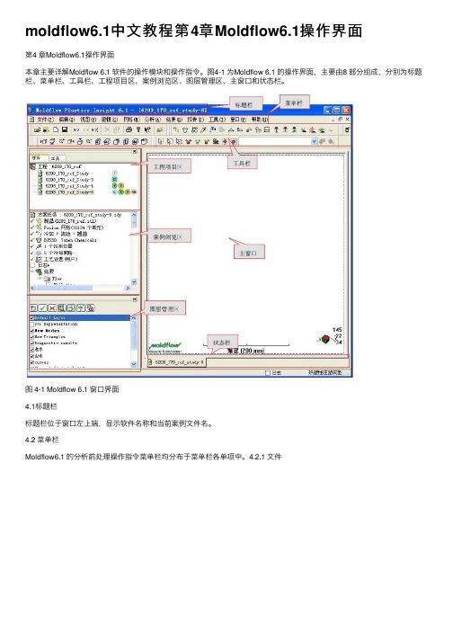
moldflow6.1中⽂教程第4章Moldflow6.1操作界⾯第4 章Moldflow6.1操作界⾯本章主要详解Moldflow 6.1 软件的操作模块和操作指令。
图4-1 为Moldflow 6.1 的操作界⾯,主要由8 部分组成,分别为标题栏、菜单栏、⼯具栏、⼯程项⽬区、案例浏览区、图层管理区、主窗⼝和状态栏。
图 4-1 Moldflow 6.1 窗⼝界⾯4.1标题栏标题栏位于窗⼝左上端,显⽰软件名称和当前案例⽂件名。
4.2 菜单栏Moldflow6.1 的分析前处理操作指令菜单栏均分布于菜单栏各单项中。
4.2.1 ⽂件图 4-2 “⽂件”下拉菜单对于项⽬⽂件的操作多在“⽂件”内完成,如图4-2 所⽰。
其下拉菜单功能如下:新建⼯程:可在设定的保存⽬录下建⽴新的⼯程项⽬,新建⼯程项⽬和已运⾏⼯程项⽬是同级的,可以互相切换处于当前活动状态。
打开⼯程:打开已存在的⼯程项⽬。
关闭⼯程:将运⾏的⼯程项⽬关闭,但不关闭模流软件。
新建:建⽴新的空⽩⽅案、报告、项⽬栏内资料夹等。
关闭:关闭当前运⾏⽅案,切换到最近上次运⾏的⽅案。
保存⽅案:保存当前运⾏⽅案。
将⽅案另存为:将当前运⾏⽅案另存为新⽅案,同时出现在⼯程项⽬区中,相当于复制原⽅案。
保存所有⽅案:保存处于运⾏状态的所有⽅案。
输⼊:在当前运⾏项⽬区中导⼊新模型。
输出:将当前分析⽅案导出,导出后的⽅案可双击或直接托进桌⾯“MF”图标中打开。
添加:在当前运⾏⽅案中添加其它模型,如调⼊1+1 模⽳中的另外⼀⽳或调⼊⼊⼦等。
组织⼯程:根据分析⽅案的属性可将同时拥有这些属性的⽅案归⼊同⼀⽂件夹下,出现在⼯程项⽬区⾥。
压缩⼯程:将分析⽣成的⽂件进⾏压缩,腾出更多磁盘空间。
⼯程属性:记录此⼯程的信息,如模流分析⼈员、公司等。
打印:打印当前显⽰窗⼝。
打印预览:预览打印效果。
打印设置:对打印效果进⾏设置。
参数设置:根据实际需求,可对系统参数进⾏个性化设置。
以下是主要的参数设置页⾯图 4-3 参数设置—概念设置页⾯在“概述”页⾯“系统”模块可以设置系统的单位、⾃动保存时间间隔;在“显⽰”模块设置表征实体处于不同情况时的颜⾊;建模基准⾯的栅格形式和⼤⼩;在“⼯程⽬录”中设置默认保存路径,便于项⽬⽂件的管理和在以后打开⽂件;在“要记住的材料数量”中可以设置显⽰在“常⽤材料列表”中塑胶材料的数量。
Moldflow软件介绍

MOLDFLOW 优化材料选择、产品、 模具设计及成型参数CAD-IT JasonMoldflow 公司简介 全球塑料注射模软件最大的供应商 1976年,发行了世界上第一套商业化的流动分析软件 1987年, 美国上市。
NASDAQ Code: MFLO The No.1 Plastic CAE company, market share:90% Branches locates in 14 countries, customers over 8,000 in 70countries. 1997年,由新科益公司带入中国市场 2000年,收购C-Mold 2008年,被AUTODESK公司收购DESIGN SOLUTIONSInformation source: Moldflow Head QuarterGlobal Company bring wider solutionEurope 36%Asia Pacific 45%America19%Corporate HQ Research & Development Manufacturing CenterDirect Sales & Support DESIGN SOLUTIONSMoldflow in your lifeDESIGN SOLUTIONSPlastic MFG Challenge in China• Plastic Material price raise • Steel for Molding Cost up • Product Development Lifecycle shorten • Customer Cost Down • Quality issue • Competition from South Asia • Communication issue • Technical people Turnover Rate is very high • Easy copy Know howDESIGN SOLUTIONSMoldflow strengthen Value ChainAutodesk® Moldflow® AdviserAutodesk® Moldflow® AdviserAutodesk® Moldflow® InsightNo Collaboration No valueAutodesk®CAE Moldflow® CommunicatorR&DAutodesk® Moldflow® CAD DoctorAssembly / ShipmentAutodesk® Moldflow® CommunicatorAutodesk® Moldflow® CommunicatorMoldingCustomer CollaborationDESIGN SOLUTIONSInjectionAutodesk® Moldflow® Communicator产品开发周期缩短试模次数 减少材料节约 2-3%注塑成本节约6-8%产品质量提高Moldflow软件费用废品率降低1%DESIGN SOLUTIONSOur End User Market SectorsAutomotive Electronics Medical Consumer Packaging Materials Contract Mfg29% 21% 9%DESIGN SOLUTIONS12% 4%3% 22%软件构架DESIGN SOLUTIONSMDL,CADDOCTOR和Communicator功能MDL功能: 没有MDL模块,Moldflow只能读入STL和IGS模型MDL For Pro/E MDL For PARASOLID MDL For CATIA V5part X_T , X_B partstep step stepCADDOCTOR 功能: 修复和简化模型, 帮助提高网格质量,大大降低网 格处理时间,提高效率。
Autodesk Moldflow 2016 中文简介
流道平衡分析平衡单型腔模具、多型腔模具和家族模具中的流道系统并优化流道尺寸,以保证所有零件能够同时充填完成,降低零件的内应力并减少塑胶材料的耗费。
热流道系统分析评估简化或详细的热流道系统设计,可详细的构建热流道系统中各部件的模型(需要各部件详细的三维几何模型)并设置顺序阀浇口,以便消除熔接线和控制保压。
塑料流动分析对塑料熔体的流动情况进行仿真分析,从而优化塑料零件和注塑模具设计、减少潜在的零件缺陷,并改善注塑成型工艺。
零件成型缺陷分析确定潜在的零件缺陷,如熔接线、困气和缩痕,然后进行设计优化以避免这些问题。
热塑性填充分析对热塑性塑料注塑成型工艺中的填充阶段进行仿真分析,以预测塑料熔体的流动模式,确保塑料熔体均匀地填充型腔,避免短射,消除或尽量避免熔接线和困气,或者改变其位置。
热塑性保压分析优化注塑成型工艺中的保压曲线,实现体积收缩量及其分布情况的可视化,从而有助于最大程度地减少塑料零件的翘曲并消除缩痕等成型缺陷。
浇注系统分析对冷、热流道系统和浇口设计进行建模和优化。
改善零件外观质量,最大限度地减少零件翘曲并缩短成型周期。
浇口位置分析可同时确定多达 10 个浇口的位置。
在确定浇口位置时,最大限度地降低注塑压力并排除特定的限制区域(如外观面)。
流道设计向导根据所输入或选择的浇注系统的排布方式、尺寸和截面类型快速创建浇注系统。
零件及模具排布分析验证和优化塑料零件、注塑模具、树脂选择和注塑成型工艺模具冷却分析评估冷却系统所确定的模具温度分布,改进冷却系统的效率,改善零件外观质量,提高零件的表面光泽度,并缩短注塑成型周期。
冷却部件的建模精确分析模具冷却系统的效率。
构建冷却水路(常规或异形水路)、隔水板、喷水管、加热元器件、蒸汽管道、感应线圈、模具镶件及模架的模型。
冷却系统分析优化模具和冷却水路设计,实现零件的均匀冷却,最大限度地缩短成型周期,减少零件翘曲,并降低制造成本。
验证高级冷却技术的应用效果及其水路的排布,如随形冷却、感应加热和瞬态冷却的计算。
MOLDFLOW模流分析
珠海优特电力科技股份有限公司
引子
我们遇到了哪些问题?
2
引子
短
射
3
引子
飞
边
4
引子
银条纹
5
引子
流 痕
6
引子
应力痕
7
引子
冲击纹
8
引子
缩 水
9
引子
熔接痕
10
引子
发 脆
11
引子
翘 曲
12
引子
如何改变传统的依靠经验的 “试错”的设计模式?
避 预知
13
目录
例如:改变保压压力,分析保压压力对成型的影响
过保压
23
保压不足
MOLDFLOW简介 功能6
冷却分析
分析冷却水路的冷却效果,冷却不均 会导致产品翘曲变形。冷却水路进出 口水温应在2℃~3 ℃为佳。
24
目录
1 2 1 3
MOLDFLOW简介 MOLDFLOW分析流程介绍 产品缺陷判定及优化对策
25
STEP2-新建工程
STEP 8-创建浇注系统和冷却系统 浇注系统
网格的划分和处 理
STEP 8-创建浇注系统和冷却系统
网格的划分和处 理
直接浇口
点浇口
侧浇口
潜伏浇口
扇形浇口
牛角浇口
STEP 8-创建浇注系统和冷却系统 冷却系统
52
STEP 8-创建浇注系统和冷却系统
OUT IN
OUT IN
IN
OUT
IN OUT
平均纵横比
33
STEP5-检查模型网格
匹配率信息 匹配率是指模型上下表面网格对 齐重合的程度。 此项是仅仅针对Fusion网格。 这也是评价网格质量的重要数据, 一般要求≥85%
Moldflow简介
Moldflow软件简介一、概述Moldflow软件可以模拟整个注塑过程以及这一过程对注塑成型产品的影响。
Moldflow软件工具中溶合了一整套设计原理,可以评价和优化组合整个过程,可以在模具制造之前对塑料产品的设计、生产和质量进行优化。
二、主要功能模块1.MF/Flow流动分析MF/Flow分析聚合物在模具中的流动,并且优化模腔的布局、材料的选择、填充和压实的工艺参数。
可以在产品允许的强度范围内和合理的充模情况下减少模腔的壁厚,把熔接线和气陷定位于结构和外观上允许的位置上,并且定义一个范围较宽的工艺条件,而不必考虑生产车间条件的变化。
2.MF/Cool冷却分析MF/Cool分析冷却系统对流动过程的影响,优化冷却管路的布局和工作条件。
MF/C ool与MF/Flow相结合,可以产生十分完美的动态的注塑过程分析。
这样可以改善冷却管路的设计,从而产生均匀的冷却,并由此缩短成型周期,减少产品成型后的内应力。
3.MF/Warp翘曲分析MF/Warp分析整个塑件的翘曲变形(包括线性、线性弯曲和非线性),同时指出产生翘曲的主要原因以及相应的补救措施。
MF/Warp能在一般的工作环境中,考虑到注塑机的大小、材料特性、环境因素和冷却参数的影响,预测并减少翘曲变形。
4.MF/Stress结构应力分析MF/Stress分析塑料产品在受外界载荷的情况下的机械性能,在考虑到注塑工艺条件下,优化塑料制品的强度和刚度。
MF/Stress预测在外载荷和温度作用下所产生的应力和位移。
对于纤维增强塑料,MF/Stress根据流动分析和塑料的种类的物性数据来确定材料的机械特性,用于结构应力分析。
5.MF/Shrink模腔尺寸确定MF/Shrink可以通过对聚合物的收缩数据和对流动分析结果来确定模腔尺寸大小。
通过使用MF/Shrink,可以在较宽的成型条件下以及紧凑的尺寸公差范围内,使得模腔的尺寸可以更准确地同产品的尺寸相匹配,使得模腔修补加工以及模具投入生产的时间大大缩短,并且大大改善了产品组装时的相互配合,进一步减少废品率和提高产品质量。
moldflow6.1中文教程第2 章Moldflow6.1 塑胶材料数据库

第2 章Moldflow6.1 塑胶材料数据库Moldflow6.1 的塑胶材料数据库中收录了丰富、全面的塑胶材料信息。
数据库中的每一种塑胶材料都有针对该材料的属性推荐的成型工艺条件;很多种材料定义了PVT数据、收缩属性参数和各向异性机械性能参数。
用户在为分析案例选择材料时,可以根据已知的材料信息,在数据库中通过不同的途径选择合适的塑胶材料。
2.1 Moldflow6.1塑胶材料数据库增补在Moldflow6.1中,塑胶材料数据库进行了内容上的增补,使材料数据库质量得到提升。
改进的材料数据显示在材料数据发表日志里,用户可以在MPI 交流中心自行下载。
以下是改进的内容:更新的热塑性材料数据库1. 供应商总数已达376家,包括14 家新添加的供应商2. 热塑性塑胶材料总数已达7734种,包括新添加322种,删除196 种,改进1275种。
其中:a. 3696 种材料定义了PVT 数据。
b. 1521 种材料有收缩数据。
c.改进Moldflow 中材料机械性能数据。
d. 多于470种塑胶新增熔体流动速率或熔体流动指数。
e.材料数据中新添材料光学属性,支持新的3D 光学双折射分析。
更新的热固性材料数据库新添11种热固性塑胶材料。
更新的模具钢材质数据库模具钢材质数据库引入更加精确的机械性能数据和热性能数据。
P20 模具钢材(系统默认的模具钢材质)的弹性模量、泊松比和热膨胀系数(MET)都已经过更新。
注意:利用更新数据后的模具钢进行冷却分析、insert molding分析和型腔移位分析,分析的结果会与以数据更新前有所不同。
2.2 选择塑胶材料在进行分析之前,先选择成型产品的塑胶材料。
点击“分析”,在其下拉菜单中选择“选择材料”指令,或直接点击案例浏览区内默认的PP料,弹出“选择材料”对话框,如图2-1所示。
图 2-1“选择材料”对话框1.常用材料:列表里存放的是经常用到的塑胶材料,选择时直接点击相应的塑胶牌号即可。
Moldflow软件介绍

MOLDFLOW 优化材料选择、产品、 模具设计及成型参数CAD-IT JasonMoldflow 公司简介 全球塑料注射模软件最大的供应商 1976年,发行了世界上第一套商业化的流动分析软件 1987年, 美国上市。
NASDAQ Code: MFLO The No.1 Plastic CAE company, market share:90% Branches locates in 14 countries, customers over 8,000 in 70 countries. 1997年,由新科益公司带入中国市场 2000年,收购C-Mold 2008年,被AUTODESK公司收购DESIGN SOLUTIONSInformation source: Moldflow Head QuarterGlobal Company bring wider solutionEurope 36% Asia Pacific 45% America19%Corporate HQ Research & Development Manufacturing Center Direct Sales & Support DESIGN SOLUTIONSMoldflow in your lifeDESIGN SOLUTIONSPlastic MFG Challenge in China• • • • • • • • • Plastic Material price raise Steel for Molding Cost up Product Development Lifecycle shorten Customer Cost Down Quality issue Competition from South Asia Communication issue Technical people Turnover Rate is very high Easy copy Know howDESIGN SOLUTIONSMoldflow strengthen Value ChainAutodesk® Moldflow® Adviser Autodesk® Moldflow® Adviser Autodesk® Moldflow® InsightNo Collaboration No valueAutodesk® Moldflow® CommunicatorCAEAutodesk® Moldflow® CommunicatorR&DAutodesk® Moldflow® CAD DoctorAssembly / ShipmentAutodesk® Moldflow® CommunicatorMoldingAutodesk® Moldflow® CommunicatorCustomer CollaborationDESIGN SOLUTIONSInjection材料节约 2-3% Moldflow软件费用 产品开发周期缩短 注塑成本节约6-8% 试模次数 减少 产品质量提高废品率降低1%DESIGN SOLUTIONSOur End User Market SectorsAutomotive Electronics Medical Consumer Packaging Materials Contract Mfg29%DESIGN SOLUTIONS21%9%12%4%3%22%软件构架DESIGN SOLUTIONSMDL,CADDOCTOR和Communicator功能MDL功能: 没有MDL模块,Moldflow只能读入STL和IGS模型 MDL For Pro/E MDL For PARASOLID MDL For CATIA V5 part X_T , X_B part step step stepCADDOCTOR 功能: 修复和简化模型, 帮助提高网格质量,大大降低网 格处理时间,提高效率。
MOLDFLOW全中文结果解释

MOLDFLOW全中文结果解释[经验] MOLDFLOW全中文结果解释!一流动分析部分1 Fill time result填充时间填充时间显示了模腔填充时每隔一定间隔的料流前锋位置。
每个等高线描绘了模型各部分同一时刻的填充。
在填充开始时,显示为暗蓝色,最后填充的地方为红色。
如果制品短射,未填充部分没有颜色。
使用:制品的良好填充,其流型是平衡的。
一个平衡的填充结果:所有流程在同一时间结束,料流前锋在同一时间到达模型末端。
这个意味着每个流程应该以暗蓝色等高线结束。
等高线是均匀间隔,等高线的间隔指示了聚合物的流动速度。
宽的等高线指示快速的流动,而窄的等高线指示了缓慢的填充。
查看项目:确认填充行为的显示状况。
短射—在填充时间结果上,短射将显示为半透明的,查看流动路径的末端是否有半透明区域。
关于3D模型, 可以使用未填充的模穴(短射)结果来检查是否在制品的内部存在未充填的部分。
滞流—如果填充时间结果显示一些区域上的云图有很近的间隔,将产生滞流。
如果一个薄区域在制品完全填充之前冻结滞流会导致短射。
过保压—如果填充时间结果显示某个流程的流程之前完成,将显示过保压。
过保压会导致高的制品重量、翘曲和不均匀的密度分布。
熔接线和气穴—在填充时间结果上重叠熔接线结果可以确定其存在,熔接线会导致结构和视觉上的缺陷。
气穴—在填充时间结果上重叠气穴结果可以确认其存在,气穴会导致结构和视觉上的缺陷。
跑道效应—跑道效应会导致气穴和熔接线,查看气穴和熔接线的位置及数量。
2 Pressure at velocity/pressure switchover resultV/P切换时刻的压力该结果从流动分析产生,显示了通过模型内的流程在从速度到压力控制切换点的压力分布。
使用:在填充开始前,模腔内各处的压力为零(或者为大气压,绝对压力)。
熔料前沿到达的位置压力才会增加,当熔料前沿向前移动填充后面的区域时压力继续增加,此取决于该位置与熔料前沿的长度。
Autodesk Simulation Moldflow 塑料注射模具注射模拟软件说明书
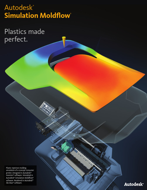
Plastics made perfect.Autodesk®Simulation Moldflow®Plastic injection moldingsimulation of a concept consumer printer. Designed in Autodesk ® Inventor ® software. Simulated in Autodesk ® Simulation Moldflow ® software. Rendered in Autodesk ® 3ds Max ® software.11Autodesk ® Simulation Moldflow ® plastic injection molding software, part of the Autodesk Simulation solution for Digital Prototyping, provides tools that help manufacturers predict, optimize, and validate the design of plastic parts, injection molds, and e xtrusion dies. Companies worldwide use Autodesk ® Simulation Moldflow ® Adviser and Autodesk ® Simulation Moldflow ® Insight software to help reduce the need for costly physical proto-types, reduce potential manufacturing defects, and get innovative products to market faster.Autodesk Simulation Moldflow Product Line Autodesk is dedicated to providing a wide range of injection molding simulation tools to help CAE analysts, designers, engineers, mold makers, and molding professionals create more accurate digital prototypes and bring better products to market at less cost.Validation and Optimization of Plastic PartsInnovative plastic resins and functional plastic part designs are on the rise in almost every industry. Plastics and fiber-filled composites answer growing pressures to reduce costs and cut time to market. The need for simulation tools that provide deep insight into the plastic injection molding process hasnever been greater.2Hot Runner SystemsModel hot runner system components and set up sequential valve gates to help eliminate weld lines and control the packing phase.Plastic Flow SimulationSimulate the flow of melted plastic to help optimize plastic part and injection mold designs, reduce potential part defects, and improve the molding process.Part DefectsDetermine potential part defects such as weld lines, air traps, and sink marks, then rework designs to help avoid these problems.Thermoplastic FillingSimulate the filling phase of the thermoplasticinjection molding process to help predict the flow of melted plastic and fill mold cavities uniformly; avoid short shots; and eliminate, minimize, or reposition weld lines and air traps.Thermoplastic PackingOptimize packing profiles and visualize magnitude and distribution of volumetric shrinkage to help minimize plastic part warpage and reduce defectssuch as sink marks.Part Layout SimulationValidate and optimize plastic parts, injection molds, resinselection, and the injection molding process.Feed System SimulationModel and optimize hot and cold runner systems and gating configurations. Improve part surfaces, minimize part warpage, and reduce cycle times.Gate LocationIdentify up to 10 gate locations simultaneously. Minimize injection pressure and exclude specific areas when determining gate location.Runner Design WizardCreate feed systems based on inputs for layout, size, and type of components, such as sprues, runners, and gates.Balancing RunnersBalance runner systems of single-cavity, multicavity, and family mold layouts so parts fill simultaneously,reducing stress levels and volume of material.3Mold Cooling SimulationImprove cooling system efficiency, minimize part warpage, achieve smooth surfaces, and reduce cycle times.Cooling Component ModelingAnalyze a mold’s cooling system efficiency.Model cooling circuits, baffles, bubblers, and mold inserts and bases.Cooling System AnalysisOptimize mold and cooling circuit designs to help achieve uniform part cooling, minimize cycle times, reduce part warpage, and decrease manufacturing costs.WarpagePredict warpage resulting from process-induced stresses. Identify where warpage might occur and optimize part and mold design, materialchoice, and processing parameters to help control part deformation.Core Shift ControlMinimize the movement of mold cores by deter-mining ideal processing conditions for injection pressure, packing profile, and gate locations.Fiber Orientation and BreakageControl fiber orientation within plastics to help reduce part shrinkage and warpage across the molded part.CAE Data ExchangeValidate and optimize plastic part designs using tools to exchange data with mechanical simulation software. CAE data exchange is available with Autodesk ® Simulation, ANSYS ®, and Abaqus ®software to predict the real-life behavior of plasticparts by using as-manufactured material properties.Rapid Heat Cycle MoldingSet up variable mold surface temperature profiles to maintain warmer temperatures during filling to achieve smooth surfaces; reduce temperatures in the packing and cooling phases to help freeze parts and decrease cycle times.Shrinkage and Warpage SimulationEvaluate plastic part and injection mold designs to help control shrinkage and warpage.ShrinkageMeet part tolerances by predicting part shrinkage based on processing parameters and grade-specificmaterial data.4Thermoset Flow SimulationSimulate thermoset injection molding, RIM/SRIM, resin transfer molding, and rubber compound injection molding.Reactive Injection MoldingPredict how molds will fill with or without fiber-reinforced preforms. Help avoid short shots due to pregelation of resin, and identify air traps and problematic weld lines. Balance runner systems, select molding machine size, and evaluate thermoset materials.Microchip EncapsulationSimulate encapsulation of semiconductor chips with reactive resins and the interconnectivity of electrical chips. Predict bonding wire deformation within the cavity and shifting of the lead frame due to pressure imbalances.Underfill EncapsulationSimulate flip-chip encapsulation to predictmaterial flow in the cavity between the chip andthe substrate.Specialized Simulation ToolsSolve design challenges with simulation.Insert OvermoldingRun an insert overmolding simulation to helpdetermine the impact of mold inserts on melt flow, cooling rate, and part warpage.Two-Shot Sequential OvermoldingSimulate the two-shot sequential overmolding process: one part is filled; the tool opens and indexes to a new position; and a second part is molded over the first.BirefringencePredict optical performance of an injection-molded plastic part by evaluating refractive index changes that result from process-induced stresses. Evaluate multiple materials, processing conditions, and gate and runner designs to help control birefringence in the part.MuCell ®MuCell ® (from Trexel, Inc.) simulation results include filling pattern, injection pressure, and cell size. These are all critical factors in optimizing a given part for the process, as well as theprocess itself.Specialized Molding ProcessesSimulate a wide range of plastic injection molding processes and specialized process applications.Gas-Assisted Injection MoldingDetermine where to position polymer and gas entrances, how much plastic to inject prior to gas injection, and how to optimize size and placement of gas channels.Co-Injection MoldingVisualize the advancement of skin and core materials in the cavity and view the dynamic relationship between the two materials as filling progresses. Optimize material combinations while maximizing the product's cost-performance ratio.Injection-Compression MoldingSimulate simultaneous or sequential polymer injection and mold compression. Evaluate material candidates, part and mold design,and processing conditions.5CAD Interoperability and MeshingUse tools for native CAD model translation and optimization. Autodesk Simulation Moldflow provides geometry support for thin-walled parts and thick and solid applications. Select meshtype based on desired simulation accuracy and solution time.CAD Solid ModelsImport and mesh solid geometry from Parasolid ®-based CAD systems, Autodesk ® Inventor ® software, CATIA ® V%, Pro/ENGINEER ®, Creo ® Elements/Pro, Autodesk ® Alias ®, Siemens ® NX ®, Rhino ®, and SolidWorks ®, as well as ACIS®, IGES, and STEP universal files.Error Checking and RepairScan imported geometry and automatically fix defects that can occur when translating a model from CAD software.Centerline Import/ExportImport and export feed system and coolingchannel centerlines from and to CAD software, to help decrease modeling time and avoid runner and cooling channel modeling errors.Autodesk Simulation Moldflow CAD Doctor Check, correct, heal, and simplify solid models imported from 3D CAD systems to prepare for simulation.3D SimulationsPerform 3D simulations on complex geometry using a solid, tetrahedral, finite element mesh technique. This approach is ideal for electrical connectors, thick structural components, and geometries with thickness variations.Dual Domain TechnologySimulate solid models of thin-walled parts using Dual Domain™ technology. Work directly from 3D solid CAD models, leading to easier simulation of design iterations.Midplane MeshesGenerate 2D planar surface meshes with assignedthicknesses for thin-walled parts.6Results Interpretation and PresentationUse a wide range of tools for model visualization, results evaluation, and presentation.Results AdviserQuery regions of a model to identify primary causes of short shots and poor part or cooling quality. Get suggestions on how to correct the part, mold, or process.Photorealistic Defect VisualizationIntegration with Autodesk ® Showcase ® software enhances quality assessments of plastic parts by examining near-photorealistic renderings of digital prototypes.Automatic Reporting ToolsUse the Report Generation wizard to create web-based reports. Prepare and share simulation results more quickly and easily with customers, vendors, and team members.Microsoft Office Export CapabilityExport results and images for use in Microsoft ® Word reports and PowerPoint ® presentations.Autodesk Simulation Moldflow Communicator Collaborate with manufacturing personnel, procurement engineers, suppliers, and external customers using Autodesk ® Simulation Moldflow ® Communicator software. Use the Autodesk Simulation Moldflow Communicator resultsviewer to export results from Autodesk Simulation Moldflow software so stakeholders can more easily visualize, quantify, and compare simulation results.Material DataImprove simulation accuracy with precise material data.Material DatabaseUse the built-in material database of grade- specific information on more than 8,500 plastic materials characterized for use in plastic injection molding simulation.Autodesk Simulation Moldflow Plastics Labs Get plastic material testing services, expert data-fitting services, and extensive material databases with the Autodesk ® Simulation Moldflow ® Plastics Labs.Productivity ToolsUse advisers and extensive help to boost productivity.Cost AdviserLearn what drives part costs to help minimize those costs. Estimate product costs based on material choice, cycle time, post-molding operations, and fixed costs.Design AdviserQuickly identify areas of plastic parts that violate design guidelines related to the injection molding process.HelpGet help on a results plot, including information on what to look for and how to correct typical problems. Learn more about solver theory, interpreting simulation results, and designing better plastic parts and injection molds.Results Evaluation and Productivity ToolsVisualize and evaluate simulation results, and use automatic reporting tools to share the results with stakeholders. Take advantage of features such as a material database and advisersto further boost productivity.Automation and CustomizationAutomate common tasks and customize Autodesk Simulation Moldflow software for your organization.API ToolsApplication programming interface (API) tools enable you to automate common tasks, customize the user interface, work with third-party applications, and help implement corporatestandards and best practices.Feature ComparisonCompare the features of Autodesk Simulation Moldflow products to learn how Autodesk Simulation Moldflow Adviser and Autodesk Simulation Moldflow Insight software can help meet the needs of your organization.78。
moldflow教材(简体中文版)
工程分析M P A培訓教材工程分析MPA培訓教材目录第一章Part Adviser简介-----------------------------------------------------------------1~3第二章开始分析--------------------------------------------------------------------------4~5 第三章塑料流动行为-----------------------------------------------------------------------6 第一节 塑料射出成型品的设计-------------------------------------------------6~16 第二节 解决充填问题-----------------------------------------------------------17~24 第四章分析结果-----------------------------------------------------------------------25~44 第五章Part Adviser操作练习-------------------------------------------------------------45 第一节Part Adviser操作界面介绍--------------------------------------------45~64 第二节 充填可行性修正--------------------------------------------------------65~72 第三节 表面品质改善-----------------------------------------------------------73~85 第六章Mold Adviser操作介绍-----------------------------------------------------------85 第一节Mold Adviser操作界面介绍------------------------------------------85~93 第二节 操作范例练习一:单模穴流道系统建立----------------------------93~97 第三节 操作范例练习二:自然平衡流道系统建立------------------------97~100 第四节 操作范例练习三:平衡非自然平衡流道系统-------------------101~105 第五节 操作范例练习四:家族模穴----------------------------------------106~109第一章Moldflow Part Adviser简介塑料射出成型是一项工业中重要的制程,制造出数以千万计的产品。
moldflow6.1中文教程第7章创建冷却系统

moldflow6.1中文教程第7章创建冷却系统第7章创建冷却系统制品冷却通常占成型周期的绝大部分时间,因此控制成型周期提高产能,加快制品冷却是至关重要的。
熔融塑胶在高温下被注射入型腔后,需要经历从高温到室温的冷却过程,在这期间熔融塑胶会释放出大量的热。
如果熔融塑胶在型腔内自然冷却至顶出温度,会需要一个很长的过程。
如果用低于模温的冷却液通过型芯,将型芯的热量带出模具从而加快制品的冷却速度。
但对于形状复杂的制品,由于冷却受限和冷却速度不一等因素,制品很容易出现各部特征产生收缩上的差异。
不合理的冷却液温度和冷却时间还会影响到内应力的释放,从而影响制品的外观、尺寸精度和机械性能。
因此需要在模腔内合理开设冷却管道,加强热量集中部位的冷却,对热量产生少的部位进行缓冷,尽量实现均匀冷却。
Moldflow 拥有分析模穴冷却管道冷却效率和冷却效果的功能。
7.1 冷却回路排布向导Moldflow 拥有自动排布冷却水路的功能,这给用户排布水路提供了极大的方便。
水路排布完成后,只需要做一些调整即可。
在排布水路前应查看型腔的布局,以防水路和其它零部件干涉。
1.旋转模型,使模型的定向与在模具型腔内的定向相同。
水路排布向导只能排布位于XY平面的水路。
2. 点击菜单栏上“建模”下拉菜单中6. 水管与制品排列方法:第一种是冷却管道与X 轴平行,第二种是冷却管道与Y 轴平行。
7. 使用默认值(D):系统会根据产品尺寸给出默认的冷却管道设置参数,如果更改后需要重新应用默认值,可点击此按钮。
8.点击“下一步”,进入对话框第二页面,如7-2所示。
a.管道数量(N):输入管道的数量。
公母模侧的冷却管道数量可能并不相同,这时可以考虑优先排布利用向导就可以完成雏形的那一侧的水路,另外一侧再通过手动进行调整。
b.管道中心之间的距离(D):输入管道之间的距离。
图 7-2“冷却回路向导”对话框第二页c.制品之外距离:冷却管道向产品外延伸的距离,由根据模仁的尺寸和模板的尺寸决定。
Autodesk Moldflow Communicator 2016 安装补充说明书
Autodesk® Moldflow® Communicator 2016 Moldflow Installation Supplement01-20-2015Autodesk® Moldflow® Communicator© 2015 Autodesk, Inc. All Rights Reserved. Except where otherwise noted, this work is licensed under a Creative Commons Attribution-NonCommercial-ShareAlike 3.0 Unported License. Please see the Autodesk Creative Commons FAQ for more information.Certain materials included in this publication are reprinted with the permission of the copyright holder.TrademarksThe following are registered trademarks or trademarks of Autodesk, Inc., and/or its subsidiaries and/or affiliates in the USA and other countries: 123D, 3ds Max, Alias, ATC, AutoCAD LT, AutoCAD, Autodesk, the Autodesk logo, Autodesk 123D, Autodesk Homestyler, Autodesk Inventor, Autodesk MapGuide, Autodesk Streamline, AutoLISP, AutoSketch, AutoSnap, AutoTrack, Backburner, Backdraft, Beast, BIM 360, Burn, Buzzsaw, CADmep, CAiCE, CAMduct, Civil 3D, Combustion, Communication Specification, Configurator 360™, Constructware, Content Explorer, Creative Bridge, Dancing Baby (image), DesignCenter, DesignKids, DesignStudio, Discreet, DWF, DWG, DWG (design/logo), DWG Extreme, DWG TrueConvert, DWG TrueView, DWGX, DXF, Ecotect, ESTmep, Evolver, FABmep, Face Robot, FBX, Fempro, Fire, Flame, Flare, Flint, ForceEffect, FormIt, Freewheel, Fusion 360, Glue, Green Building Studio, Heidi, Homestyler, HumanIK, i-drop, ImageModeler, Incinerator, Inferno, InfraWorks, InfraWorks 360, Instructables, Instructables (stylized robot design/logo), Inventor, Inventor HSM, Inventor LT, Lustre, Maya, Maya LT, MIMI, Mockup 360, Moldflow Plastics Advisers, Moldflow Plastics Insight, Moldflow, Moondust, MotionBuilder, Movimento, MPA (design/logo), MPA, MPI (design/logo), MPX (design/logo), MPX, Mudbox, Navisworks, ObjectARX, ObjectDBX, Opticore, Pixlr, Pixlr-o-matic, Productstream, Publisher 360, RasterDWG, RealDWG, ReCap, ReCap 360, Remote, Revit LT, Revit, RiverCAD, Robot, Scaleform, Showcase, Showcase 360, SketchBook, Smoke, Socialcam, Softimage, Sparks, SteeringWheels, Stitcher, Stone, StormNET, TinkerBox, ToolClip, Topobase, Toxik, TrustedDWG, T-Splines, ViewCube, Visual LISP, Visual, VRED, Wire, Wiretap, WiretapCentral, XSI.All other brand names, product names or trademarks belong to their respective holders.DisclaimerTHIS PUBLICATION AND THE INFORMATION CONTAINED HEREIN IS MADE AVAILABLE BY AUTODESK, INC. "AS IS." AUTODESK, INC. DISCLAIMS ALL WARRANTIES, EITHER EXPRESS OR IMPLIED, INCLUDING BUT NOT LIMITED TO ANY IMPLIED WARRANTIES OF MERCHANTABILITY OR FITNESS FOR A PARTICULAR PURPOSE REGARDING THESE MATERIALS.ContentsChapter 1Introduction to Product Installation . . . . . . . . . . . . . . . . 1 About Preparing for Installation . . . . . . . . . . . . . . . . . . . . . . 1About Product Language Selection . . . . . . . . . . . . . . . . . . . . . 3About the Installation Path and Product Configuration . . . . . . . . . . 3Chapter 2Windows Installation . . . . . . . . . . . . . . . . . . . . . . . . 5 To Install this Product . . . . . . . . . . . . . . . . . . . . . . . . . . . 5User Interface Language . . . . . . . . . . . . . . . . . . . . . . . . . . 6Uninstall the product . . . . . . . . . . . . . . . . . . . . . . . . . . . . 6Chapter 3Frequently Asked Questions . . . . . . . . . . . . . . . . . . . . 9 What if I want to install to a different location? . . . . . . . . . . . . . . 9Do I have to install all configuration options at once? . . . . . . . . . . 9Can I install different products to different locations? . . . . . . . . . . 9iiiivIntroduction to Product Installation This Install Guide is divided into different sections:■An overview of the installation process using the Autodesk installer, how to prepare for the process, and some useful background information.■Steps to follow for installing on a Windows operating system ■Frequently asked questions about product installation Further details are provided in the following sections.IMPORTANT This overview describes the various pages of the installer to help you navigate the installation. For Autodesk ® Moldflow ® Communicator which does not require licensing, many of the items described are not options, despite being part of the installer. Please disregard all references to licensing in this Install Guide.About Preparing for InstallationA checklist of prerequisites.Before starting to install, check the following details:■Confirm that your computer meets the minimum system requirements. If in doubt, click System Requirements at the bottom of the installer screen.■Review product documentation to clarify details such as the type of installation to do, and which products to install. Documentation is accessiblefrom links on the lower left corner of the installer:11■Ensure that your user name has Administrator permissions to installapplications on the computer or network.■Obtain serial numbers and product keys for all products you want to install.These are on the product package or email provided at the time youdownload the software.■When you are ready to run the installer, close all running applications.Windows 8/8.1 and the .NET 3.5 RequirementSome Autodesk products require Microsoft DirectX, which, in turn, requiresthe Microsoft .NET Framework. But Windows 8/8.1 has enforced restrictionson installing .NET 3.5 and earlier versions from local media. Therefore,Autodesk products require Internet access so that Windows Update can installor enable the .NET Framework.If the Autodesk installer is unable to install .NET 3.5 or an earlier version onWindows 8/8.1, the following message appears:An Internet connection is required to install a Windows component.Please connect and re-launch the installer.The .NET installation is prevented by any of the following conditions:■An Internet connection is not available during installation.■The computer is configured to use Windows Server Update Services (WSUS) instead of Windows Update.■The Windows 8/8.1 update for Microsoft Security Advisory ( 2749655) is not installed.If any of these conditions cannot be resolved, then the System Administratoror user must manually enable .NET 3.5 on each Windows 8/8.1 computerbefore running the Autodesk installer.To manually enable .NET 3.5 on a Windows 8/8.1 computer1Right-click Start screen ➤ All Apps ➤ Control Panel ➤ Programs ➤Turn Windows Features On or Off.2In the feature list, select Microsoft .NET Framework 3.5, ensuring that a check mark is visible for this feature.3Click OK.For more information, see the following MSDN article.2 | Chapter 1 Introduction to Product InstallationAbout Product Language SelectionYou can select the language you want to use during installation, using thisdrop-down menu on the installer:Language Selection MenuYou can also select the language for the installed product on the ProductInformation page, when you enter the serial number and other productinformation. If you install the product with one language, and then find youwant to use a different language, you can run the installer again and selectthe different language on the Product Information page, by clicking onthe Information button and following the instructions.These conditions apply to product language selection:■All deployments must be in a single language. One administrative image can support deployments for different languages, but each deployment isfor one language.■If you are installing multiple products and select a language that is not supported by some products, these products use a default language. About the Installation Path and Product Configur-ationInstallation PathThis path specifies where the product folder will be installed. If you changethe location, use only valid ASCII characters in the install path.Product ConfigurationOn the Configure Installation page, for every product listed there is atriangular control which you can click for access to a configuration panel.Click anywhere in the product box to open the configuration panel. For manyproducts, you can select an installation type, either Typical to accept theAbout Product Language Selection | 3default configuration settings, or Custom to review the settings and decidewhether to modify them.4 | Chapter 1 Introduction to Product Installation2 Windows InstallationAutodesk Moldflow Communicator uses an installation Wizard to guide you through the installation process.To Install this ProductThe Installation Wizard guides you through several steps. See the InstallationOverview for additional information.1Uninstall (page 6) any pre-release versions you may have.2If installing from a downloaded executable file, navigate to the■file, right click on it, and double-click on the installationexecutable to start the installation.3In the Welcome page, click Install to begin the installation process.4In the License Agreement page,■Select the appropriate entry in the Country or Region list.■Review the agreement.■Select the option to accept the agreement, then click Next.NOTE If you reject the license agreement, you cannot install thesoftware.5In the Product Information page,■Select the Product Language.■Click Next.56In the Configure Installation page, all the available software isselected by default. If you don't want to install everything now,deselect the options you don't want.■Accept the default Installation Path, or click Browse to selecta different folder.■Click Install to start the process.7The Wizard begins installing the software. In the InstallationProgress page a progress indicator shows how much of theinstallation has been completed. Once the installation is complete,the Installation Complete page appears. The successfully installedproducts are listed, as are any products that failed to install.8Click Finish to close the Setup Wizard.User Interface LanguageThe User Interface is available in the following languages:■Chinese (Simplified)■Chinese (Traditional)■English■French■German■Italian■Japanese■Korean■Portuguese■SpanishUninstall the productThe Uninstall feature enables you to remove this product from yourWindows-based computer. You should remove this product from yourcomputer if you plan to upgrade it to a newer version, or if you would like tochange the configuration settings.■Open the Windows Start menu and navigate to the Autodesk Folder.■Click the Uninstall tool and select the product you want to uninstall.6 | Chapter 2 Windows Installation■Click Uninstall then click Exit when the process is complete.Uninstall the product | 783 Frequently Asked Ques-tionsWhat if I want to install to a different location?During installation, you can install to a different location by changing theinstallation path to another valid drive or folder on your computer. Autodesktools, utilities, and service packs will be able to find the installed location. Do I have to install all configuration options at once?For many installers, the Configure Installation page provides a list of productsthat can be installed. You can choose to install as many or as few of these asyou want. If you have already installed other Autodesk products, some of theseoptions may already be installed.If you do not want to install all these options, you can install them at a latertime by relaunching the installer.NOTE You will need your license information to relaunch the installer.Can I install different products to different loca-tions?All products installed at the same time will be installed to the Installation pathindicated at the bottom of the Configure Installation page.9If you would like to install products to different locations, install each productseparately, changing the installation path for each installation.NOTE Some products must be installed to the same path as related products. Inthis case, a warning will be provided, indicating that the Installation path hasalready been set by a previous installation.10 | Chapter 3 Frequently Asked Questions。
moldflow6.1中文教程第3 章Moldflow6.1 分析流程介绍
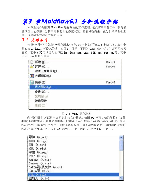
第3 章Moldflow6.1 分析流程介绍本章主要介绍使用Moldflow进行分析的工作流程,包括前期准备工作、获得最佳成型工艺参数、分析中需要的工艺参数设置、查看分析结果、在分析结果基础上做出改善措施等详细的操作步骤。
3.1 文件另存选择“文件”下拉菜单中“保存副本”指令,将一个完好的CAD 档在CAD软件中另存为moldflow可读入的档,如图3-1所示。
不同的CAD 软件可以生成不同的另存档,其中MPI可以读入的包括igs,iges,ans,unv,bdf,pat,out,stl 等。
其中以stl、igs档最为常用。
图3-1 Pro/E 保存副本在“保存副本”对话框中选择副本的文件格式,如图3-2 所示。
如果转档时“文件类型”下拉框里没有那种文件类型,比如在Pro/E 中将Part 档另存为stl 时,表明Part 档存在局部残破的情况,可能不影响拆模,但无法成功转档。
这时可以考虑将Part 档另存为stp 档,从Pro/E 转到UG 中,再以stl 档从UG 中转出。
图3-2 Pro/E 选择副本的文件格式3.2 另存文件格式对网格划分的影响转档时不同文件格式对moldflow 中网格划分有不同的影响:1. 另存为stl。
在Pro/E 中以Part 档为源档转出的情况最多,其优点为在精度控制得当的情况下,显示成功转出后的stl 档不会丢失源档的特征。
缺点是对源档点、线、面的完好性要求高,必须是完好无损的源档才能以STL 档转出。
2. 另存为igs 档。
优点是网格匹配率较stl 高一些,缺点是在源档残破的情况下也能转出,但由于无提示信息,转档过程中一旦出现重叠或缺失的特征,不仅增加网格的缺陷,细小的特征还会因无意识丢失而很难被发现,造成分析失误增加。
对于某些重要的细小特征的遗失,有时要等到去查看那里的缩水或其他成型问题时才会被发现,耽搁了宝贵的时间。
所以一定要慎用igs档。
3.3 编辑输出模型的精度图3-3 “输出副本文件”Pro/E 对话框确定副本文件格式后弹出“输出副本文件”对话框,如图3-3 所示。
- 1、下载文档前请自行甄别文档内容的完整性,平台不提供额外的编辑、内容补充、找答案等附加服务。
- 2、"仅部分预览"的文档,不可在线预览部分如存在完整性等问题,可反馈申请退款(可完整预览的文档不适用该条件!)。
- 3、如文档侵犯您的权益,请联系客服反馈,我们会尽快为您处理(人工客服工作时间:9:00-18:30)。
流道平衡分析
平衡单型腔模具、多型腔模具和家族模具中的流道系统并优化流道尺寸,以保证所有零件能够同时充填完成,降低零件的内应力并减少塑胶材料的耗费。
热流道系统分析
评估简化或详细的热流道系统设计,可详细的构建热流道系统中各部件的模型(需要各部件详细的三维几何模型)并设置顺序阀浇口,以便消除熔接线和控制保压。
塑料流动分析
对塑料熔体的流动情况进行仿真分析,从而优化塑料零件和注塑模具设计、减少潜在的零件缺陷,并改善注塑成型工艺。
零件成型缺陷分析
确定潜在的零件缺陷,如熔接线、困气和缩痕,然后进行设计优化以避免这些问题。
热塑性填充分析
对热塑性塑料注塑成型工艺中的填充阶段进行仿真分析,以预测塑料熔体的流动模式,确保塑料熔体均匀地填充型腔,避免短射,消除或尽量避免熔接线和困气,或者改变其位置。
热塑性保压分析
优化注塑成型工艺中的保压曲线,实现体积收缩量及其分布情况的可视化,从而有助于最大程度地减少塑料零件的翘曲并消除缩痕等成型缺陷。
浇注系统分析
对冷、热流道系统和浇口设计进行建模和优化。
改善零件外观质量,最大限度地减少零件翘曲并缩短成型周期。
浇口位置分析
可同时确定多达 10 个浇口的位置。
在确定浇口位置时,最大限度地降低注塑压力并排除特定的限制区域(如外观面)。
流道设计向导
根据所输入或选择的浇注系统的排布方式、尺寸和截面类型快速创建浇注系统。
零件及模具排布分析
验证和优化塑料零件、注塑模具、树脂选择和注塑成型工艺
模具冷却分析
评估冷却系统所确定的模具温度分布,改进冷却系统的效率,改善零件外观质量,提高零件的表面光泽度,并缩短注塑成型周期。
冷却部件的建模
精确分析模具冷却系统的效率。
构建冷却水路(常规或异形水路)、隔水板、喷水管、加热元器件、蒸汽管道、感应线圈、模具镶件及模架的模型。
冷却系统分析
优化模具和冷却水路设计,实现零件的均匀冷却,最大限度地缩短成型周期,减少零件翘曲,并降低制造成本。
验证高级冷却技术的应用效果及其水路的排布,如随形冷却、感应加热和瞬态冷却的计算。
注塑成型工艺的仿真
翘曲分析
预测由成型应力所导致的产品翘曲。
找出可能发生翘曲的部位,并优化零件和模具设计、材料选择和工艺参数,以帮助控制零件的变形。
型芯偏移分析
通过优化注塑压力、保压曲线、浇口位置、模具型芯的结构及固定方式等参数,找出最佳的工艺条件,预测并最大限度地减少模具型芯在成型过程中的变形。
纤维取向分布和断裂分析
通过最新的长、短玻纤求解器,以及先进的长玻纤断裂分析功能,帮助用户预测并控制注塑零件中的纤维取向分布,减少成型过程中的长玻纤断裂,以便减少注塑零件的收缩和翘曲。
CAE 数据交换
使用数据交换工具使 Moldflow 与结构分析软件进行数据交换和联合仿真,帮助验证和优化塑料零件的设计。
可与 Autodesk ® Simulation Mechanical 、Autodesk ® Nastran ® 和 ANSYS ®、 Abaqus ® 等 CAE 软件实现数据交换,从而实现根据实际制造后的产品的材质属性预测塑料零件的实际性能。
快速热循环成型(急冷急热成型)分析
基于瞬态模具温度分析的功能,通过设置模具表面温度变化曲线或模具加热器(热电偶、蒸汽或电磁等),使模具在填充阶段维持较高温度以改善充填并使表面光滑、消除熔接线;在保压和冷却阶段快速降低模具温度以冷却零件,缩短成型周期。
收缩和翘曲分析
评估塑料零件和注塑模具设计,帮助控制收缩和翘曲。
收缩分析
根据工艺参数和具体的材料数据预测零件的收缩率,以确保零件满足设计公差的要求。
热固性塑料流动分析
对热固性塑料注塑成型、RIM/SRIM 、树脂传递成型以及橡胶复合材料的注塑成型进行仿真。
反应注塑成型
评估含或不含纤维增强的热固性材料的充填效果,避免因树脂提前固化所造成的短射,预测困气或熔接线问题。
平衡流道系统,选择注塑机规格并评估热固性材料的选择。
微芯片封装
对利用树脂封装的半导体芯片以及电子芯片的封装过程进行仿真。
预测因为树脂流动或压力不均匀而造成的型腔变形和引线架的位移。
覆晶封装
对倒装芯片封装工艺进行仿真,预测材料在芯片和基板之间的型腔内的流动情况。
专业的仿真分析工具
通过仿真分析解决设计挑战。
嵌入成型分析
进行嵌入成型的仿真分析,帮助确定模具镶件或产品嵌件对熔体流动、模具冷却效率和零件的翘曲变形的影响。
双色成型分析
对双色成型工艺进行仿真分析:填充一个零件,然后打开模具,后模旋转到新位置,在第一个零件上方注射第二个零件。
双折射分析
评估由成型应力所引起的产品折射率的变化,以此预测注塑成型零件的光学性能。
评估不同材料、工艺参数以及浇口和流道的设计,以便控制零件的折射率。
MuCell ® 分析
MuCell ®(Trexel 公司的专利技术)仿真结果包括填充模式、注塑压力和细胞大小和分布。
这些结果对于优化 Mucell 成型工艺本身或使用该工艺的零件都至关重要。
特殊的成型工艺
对广泛的塑料注塑成型工艺流程和特殊的工艺流程进行仿真。
气体辅助注塑成型分析
确定浇口和进气口的位置,确定在充气前的熔体注塑体积,以及如何优化气道的尺寸和排布。
共注塑成型分析
实现型腔内的皮层材料和型芯材料的注塑过程的可视化,填充过程中查看这两种材料流动状态之间的动态关系。
优化材料组合,同时最大限度地提高产品的性价比。
注压成型或纯压缩成型分析
注压成型或纯压缩成型工艺的仿真分析。
在这种工艺中,聚合物的注入和模具的压缩阶段可同步或先后进行。
评估材料的选择,优化零件设计、模具设计以及工艺参数。
特殊注塑成型工艺的仿真
产品功能对比
比较不同 Autodesk Moldflow 产品的功能,了解 Autodesk Moldflow Adviser 和 Autodesk Moldflow Insight 软件如何满足贵公司的需求。
Autodesk
Moldflow Flex Autodesk Moldflow Adviser Autodesk Moldflow Insight
标准版标准版高级版旗舰版标准版高级版旗舰版求解器功能
本地求解数量(最大)1---133云端求解
网格划分
双层面网格技术
3D 实体网格分析技术
中面网格技术
CAD 协同
CAD 实体模型
零件
装配体
仿真分析工具
设计分析工具
结果分析工具
成本分析工具
仿真功能
填充
保压
纤维取向
表面缺陷预测
成型窗口
排气分析
结晶分析
浇口位置
冷&热流道
流道平衡
实验设计 (DOE)
冷却
瞬态模具冷却或加热
随形冷却
急冷急热
感应加热
加热元器件
翘曲
嵌入成型
模内装饰
双色成型
型芯偏移
金线偏移、晶垫偏移
成型工艺
热塑性塑料注塑成型
气体辅助注塑成型
注压成型或纯压缩成型分析
共注塑成型
Autodesk
Moldflow Flex Autodesk Moldflow Adviser Autodesk Moldflow Insight
标准版标准版高级版旗舰版标准版高级版旗舰版成型工艺(续)
双组份注塑成型
微孔发泡注塑成型
双折射
树脂传递和结构反应注塑成型
橡胶、液态硅胶注塑成型
多料筒反应成型
反应注塑成型
微芯片封装
覆晶封装
压缩成型
数据库
热塑性塑料材料
热固性材料
注塑机
冷却液材料
模具材料
软件互操作性
Simulation Mechanical (FEA)
Autodesk Nastran (FEA)
Abaqus (FEA)
ANSYS (FEA)
LS-DYNA (FEA)
CODE V(双折射)
VRED(缺陷可视化)
Showcase(缺陷可视化)
CADdoctor for Autodesk Simulation
支持的语言
英语
简体中文
繁体中文
法语
德语
意大利语
日语
葡萄牙语
西班牙语
朝鲜语
包含的软件和服务
Moldflow Communicator
SimStudio Tools
Vault
*部分工艺/分析类型可能不支持所有网格类型。
