KJ-2091可程式恒温恒湿试验箱
可程式恒温恒湿试验箱技术参数

可程式恒温恒湿试验箱技术参数可程式恒温恒湿试验箱用于考察电工电子产品、元器件、零部件及其材料在不同温湿度条件下,其耐潮湿能力,还可以作为在高低温环境下储存、运输和使用的适应性试验。
技术参数1)温度测量范围:-40.00*C~150.00°C(分辨率:0.01C,误差+0.5°C);2)5.7寸TEM彩色触摸屏;(定值/编程)两种控制方式;中(英)文菜单提示;3)PT100传感器;PID控制输出;(4-20mA)模拟输出;4)8路开关信号辅助输出;(基本配置10点,可选配置20点)5)ON/OFF继电器输出;6)程式编辑(可编120个程式,每个程式为99段)。
7)附属功能报警显示功能,停电保护功能,上限温度报警功能,定时功能(自动启动及自动停止),自诊断功能,曲线记录显示功能。
8.材质内壁#SUS304镜光板9、外壳#SUS304钢板1.2MM10、保温材料耐高温高密度氯基甲酸乙醋泡沫绝缘体材料11、系统风路循环方式离心风机-宽带式强迫气流循环(.上出下进)12、制冷方式二元复叠式制冷(即2台压缩机)采用法国“泰康”全封闭制冷压缩机组,每台机组均经过欧洲“泰康”电脑联网逐项监测并有防伪编码可通过电脑上网查寻13、制冷机全封闭活塞式法国泰康压缩机14、制冷剂R4O4A或美国杜邦环保冷媒(R23+R404)15、冷凝方式风冷16.加热器镍铬合金电热丝加热器17、加湿器半封闭蒸气加湿18、供水方式全自动循环供水19、标准配置观视窗(双层中空钢化玻璃)1个.50mm测试孔位于左侧1个、PL箱内灯1个、隔板2块、干湿球纱布1包,保险丝3个,电源线1条。
20.安全装置无熔丝开关、[压缩机过载、冷媒高低压、超湿度超温]保护开关、保险丝故障警告系统21、电源220VAC+10%50/60Hz恒温恒湿试验箱是航空、汽车、家电、科研等领域必备的测试设备,用于测试和。
mil-std-202f《电子及电气元件试验方法》可程式盐雾试验箱
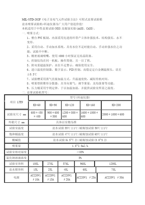
MIL-STD-202F《电子及电气元件试验方法》可程式盐雾试验箱
盐水喷雾试验机-科迪仪器为广大用户创造价值!
本机适用于中性盐雾试验(NSS)及腐蚀实验(AASS、CASS)。
一. 喷雾方式:
1、整台PVC板制,内部采用先进的环带产立体补强技术,结构强实,永不
变形。
2、采用自动、手动加水系统,具有水位不足时能自动、手动补强水位之功
能,试验不中断。
3、精密玻璃喷嘴,使用4000小时保证无结晶阻塞。
4、控制仪均在同一机板,操作简便,且一目了然。
5、附双重超温保护,水位不足警示,确保使用安全。
6、进口温度控制器,数字显示,PID控制,高稳定定白金测温探头,误差
±0.3℃
7、试验槽采用蒸气直接加温方式,升温速度快,减短待机时间。
8、喷雾塔附锥形分散器,具导向雾气,调节雾量,及均落雾等功能。
9、压力桶采用亨利定律,于以加温加湿,并提供试验室所需之湿度。
科迪仪器主营:
紫外光耐气候试验箱;紫外线加速耐候试验机;盐水喷雾试验机,盐雾箱,盐水浸泡腐蚀试验箱,盐水浸泡试验机,恒温恒湿仪,高低温试验箱,高低温交变湿热箱;
可程式恒温恒湿试验机;温湿度检定箱;高低温恒温试验箱;高低温冲击试验箱;
蓄温式冷热冲击试验机;步入林环境实验室;步入式恒温恒湿试验室;精密烘箱;
盐水喷雾试验机;模拟运输试验机;蒸气老化试验机;快速温变应力筛选试验机,电解测厚仪,电镀测厚仪,老化试验机,投影仪,影像测量仪,硬度计,色差计;其它环境试验设备.
*另可依客户要求之尺寸制作试验室,满足客户的要求。
*欢迎广大客户来电来函咨询订购!(135****9144王玲)。
恒温恒湿试验箱的基本使用要点及操作规程
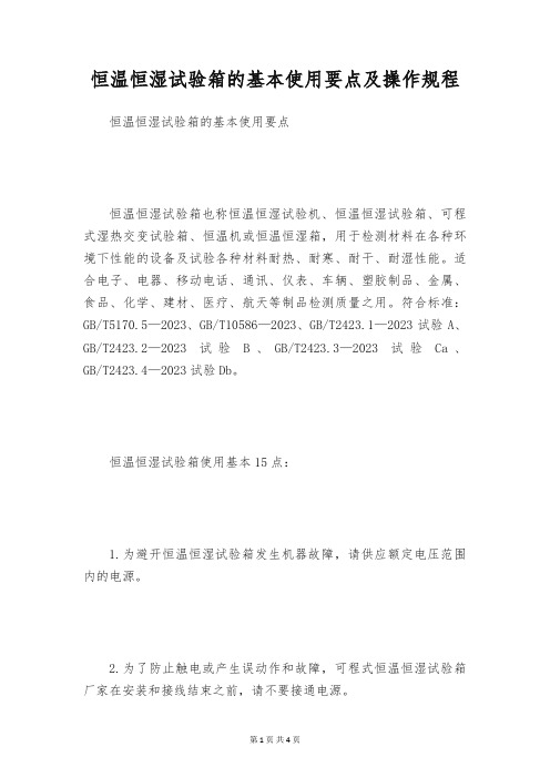
恒温恒湿试验箱的基本使用要点及操作规程恒温恒湿试验箱的基本使用要点恒温恒湿试验箱也称恒温恒湿试验机、恒温恒湿试验箱、可程式湿热交变试验箱、恒温机或恒温恒湿箱,用于检测材料在各种环境下性能的设备及试验各种材料耐热、耐寒、耐干、耐湿性能。
适合电子、电器、移动电话、通讯、仪表、车辆、塑胶制品、金属、食品、化学、建材、医疗、航天等制品检测质量之用。
符合标准:GB/T5170.5—2023、GB/T10586—2023、GB/T2423.1—2023试验A、GB/T2423.2—2023试验B、GB/T2423.3—2023试验Ca、GB/T2423.4—2023试验Db。
恒温恒湿试验箱使用基本15点:1.为避开恒温恒湿试验箱发生机器故障,请供应额定电压范围内的电源。
2.为了防止触电或产生误动作和故障,可程式恒温恒湿试验箱厂家在安装和接线结束之前,请不要接通电源。
3.在开机之前要查看电源是否稳定。
4.接线必需正确,确定要进行接地。
恒温恒湿试验箱说明书不接地可能造成触电、错误动作事故、显示不正常或测量有较大误差。
5.机器安装设置时注意不要让灰尘、线头、铁屑或其他东西进入,否则会发生错误动作或故障。
6.仪器工作中请尽量不要打开试验箱门,高温时打开可能会对操作人员造成烫伤,低温时打开可能会对工作人员造成冻伤,并且可能造成蒸发器结冰,影响制冷效果。
若确定要打开,请做好确定的防护工作。
7.仪表在运转中,进行修改设定、信号输出、启动、停止等操作之前,应充分地考虑安全性,错误的操作会使工作设备损坏或发生故障。
8.恒温恒湿试验箱仪表运转期间,电源入力端子盖必需安装在端子板上以防触电。
9.请使用干布擦拭仪表,不要使用酒精、汽油或其他有机溶剂,不要把水溅到仪表上,假如仪表浸入水中,请立刻停止使用,否则有漏电、触电或火灾的不安全。
10.定期检查端子螺丝和固定架,请不要在松动的情况下使用。
11.仪表内部零件有确定的寿命期限,为持续安全地使用本仪表,请定期进行保养和维护。
可程式恒温恒湿试验箱技术规格
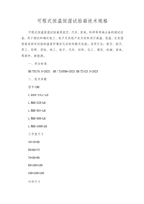
可程式恒温恒湿试验箱技术规格可程式恒温恒湿试验箱是航空、汽车、家电、科研等领域必备的测试设备,用于测试和确定电工、电子及其他产品及材料进行高温、低温、交变湿热度或恒定试验的温度环境变化后的参数及性能。
适用行业:航空、航天、军工、科研、质检、电工、电子、汽车、材料、化工、通讯、机械、家电、零部件、新能源。
一、符合标准GB/T5170.5-2023、GB∕T10586-2023.GB/T2423.3-2023二、技术参数型号(CM)1.RHS-IOi-LH1.RHS-225-LH1.RHS-504-LH1.RHS-800-LH1.RHS-1000-LH工作室尺寸45*45*5050*60*7570*80*9080*100*100100*100*100外形尺寸120*100*165 130*115*190 145*140*210 155*160*225 185*160*225 功率4.0(KW)5.5(KW)7.0(KW)9.O(KW) 11.5(KW)性能指标温度范围0℃〜150℃湿度范围30〜98%R.H 波动/均匀度±0.5℃/±2℃湿度偏差+2、-3%R.H升温速率1.0-3.0o C∕min降温速率O.7-1.0o C∕min控制系统控制器日本原装进口“优易控”品牌温度仪表,7寸高清真彩液晶触摸显示屏精度范围设定精度:温度0.1℃、湿度1%R.H,指示精度:温度0.1℃.湿度1%R.H 传感器铀金电阻.PT100Q/MV加热系统全独立系统,银辂合金电加热式加热器加湿系统外置隔离式,全不锈钢浅表面蒸发式加湿器除湿系统采用蒸发器盘管露点温度层流接触除湿方式供水系统加湿供水采用自动控制.且可回收余水.节水降耗制冷系统法国原装“泰康”全封闭风冷式压缩机制冷方式循环系统耐温低噪音空调型电机.多叶式离心风轮使用材料外箱材质优质碳素钢板.磷化静电喷塑处理/SUS304不锈钢雾面线条发纹处理内箱材质SUS304不锈钢优质镜面光板保温材质聚氨酯硬质发泡/超细玻璃纤维棉门框隔热双层耐高低温老化硅橡胶门密封条标准配置附照明玻璃视窗1套、试品架2个、测试引线孔(25、50、100mm)1个安全保护漏电、短路、超温、缺水、电机过热、压缩机超压、过载、过电流保护/控制器停电记忆电源电压AC380V±10%50±0.5Hz三相五线制使用环境温度5°C~+30°C≤85%R.H注:1、“LP/DHS”为可程式恒温恒湿试验箱型号。
可程式恒温恒湿试验机说明书
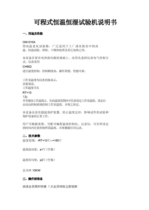
可程式恒温恒湿试验机说明书一、用途及性能GW-010A型高温老化试验箱,广泛适用于工厂或实验室中的高温、恒温试验、烘焙、干燥热处理及其它加热之用。
本设备在原有电热鼓风箱的基础上,改用先进的仪表电气控制方式,仪表采用CH902进行温度控制,控制精度高,操作简便,性能可靠,工作室温度为仪表直接显示,直观易读,工作温度可从RT+10℃起升至最高工作温度止。
在此温度范围内可任意设定工作室温度,设定后由反动控制系统控制工作室温度,并使之恒定。
本设备还设有超温保护装置,防止温度过冲,影响试件的试验和保护设备的正常工作。
用户可根据需要,另配可编程温度控制仪、记录仪,可在所设定的时间内任意控制所需温度,并将数据打印记录。
二、技术参数温度范围:-RT+10℃--+150℃温度波动度:±1℃(空载)温度均匀度:≤2℃(空载)总功率10KW三、操作前准备阅读会员限时特惠 7大会员特权立即尝鲜1.该箱应该放在室内干燥水平处。
2.在供电线路中需安装断路器一只,供本设备专用,并用比电源电线粗一倍的导线作接地线。
3.通电前先检查本箱的电气性能,并应注意是否有断路或漏电现象。
4.待一切准备就绪,可将试品放入箱内样品架,关上箱门。
四.操作面板及功能㈠接通电源。
㈡将试品放入箱内,关好箱门,开启..电源开关,此时仪表有显示,再分别按下风机和加热开关,设备便进入正常状态。
㈢.温控仪设定:控温仪面板功能及操作流程①(PV)显示器(绿)•显示测量值。
•根据仪表状态显示各类提示符。
②给定值(SV)显示器(横黄)•显示给定值。
•根据仪表状态显示各类参数。
③指示灯•自整定指示灯(AT)(绿)工作时闪烁。
•控制输出灯(OUT1)(绿)工作输出时亮。
•冷侧控制输出灯(OUT2)(绿)工作输出时亮。
•报警输出灯(ALM)(红)工作输出时亮。
•连续输出时,输出范围内(OUT1)(绿)灯闪烁。
④设定键:参数的调出,参数的修改确认。
⑤、⑥、⑦数字调整键:用于调整数字或进入自整定状态操作方法1. 在说明书的以下说明中未提及的参数设定请不要进入或修改,随意修改会引起设备故障,请设备管理者与使用者注意。
QMS-C-AS-209-01 高温特性测试技术研究说明书
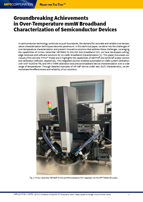
As semiconductor technology continues to push boundaries, the demand for accurate and reliable over-tempe-rature characterization techniques becomes paramount. In this technical paper, we delve into the challenges of over-temperature characterization and present innovative solutions that address these challenges. Leveraging the capabilities of Anritsu VectorStar ME7838G 70 kHz–220 GHz broadband VNA, we have developed cutting-edge hardware and software solutions for on-wafer broadband characterization [1]. This paper showcases our industry-first 220 GHz TITAN™ Probe and it highlights the capabilities of SENTIO® and QAlibria® prober control and calibration software, respectively. The integrated solution enabled automated on-wafer system calibration with NIST multiline TRL and MPI’s TMRR calibration and precise broadband device characterization over a wide range of temperatures. Through detailed examples of InP HBT device under test (DUT) characteristics, we de -monstrate the effectiveness and reliability of our solutions.Groundbreaking Achievementsin Over-Temperature mmW Broadband Characterization of Semiconductor DevicesFig. 1: Anritsu VectorStar ME7838G 70 kHz–220 GHz broadband VNA integrated with the MPA TS3500-SE system.ISOTHERMAL BROADBAND MEASUREMENTS AND CALIBRATIONBroadband measurements and calibration are critical in semiconductor testing. They comprehensively explore device behavior and verify device model parameters in a wide frequency range, ensuring the final product per -formance optimization and specification at its true operation frequencies.Accurate calibration corrects systematic errors, enhancing measurement data accuracy. It ensures precise and repeatable data, supporting accurate data analysis and the right results interpretation.The extraction of compact model parameters and the validation of IC designs require data acquisition over a wide temperature range, typically from -40 °C to +125 °C or even higher. This requirement adds another dimen -sion to the complexity of characterizing broadband mmW devices. Advanced integrated probe systems and so -phisticated RF calibration software that support advanced calibration techniques can greatly simplify this task.The seamless integration of modern single-sweep broadband vector network analyzers, such as the Anritsu Vec -torStar ME7838G 70 kHz–220 GHz broadband VNA, with the MPI TS3500-SE probe system featuring the IceFree -Environment™ option, broadband TITAN™ Probes T220A, and SENTIO® embedded QAlibria® calibration software, along with automated probe-to-pad alignment, contact quality, data consistency, and calibration accuracy ve-rification enables unattended broadband device characterization across the entire frequency and temperature ranges (Fig. 1).RF probes can experience drift due to temperature expansion. As the temperature changes, the materials com -posing the probe can expand or contract, causing mechanical stress and altering the probe’s electrical proper -ties. This drift can lead to measurement inaccuracies and inconsistent results. Furthermore, it’s important to note that the measurement system can also be affected by drift, not just due to temperature but also overall sta -bility. Factors such as the stability of the vector network analyzer (VNA) and the phase stability of the RF cables used in the setup can contribute to measurement drift. Ensuring proper calibration and monitoring of these components is essential to mitigate the impact of drift and maintain accurate RF measurements.A crucial technique we employ is calibrating at each temperature point, and our calibration software effectively manages this process. The software provides an intuitive step-by-step guide that assists the user in executing a meticulous calibration procedure. Users can follow the software’s instructions to take the necessary steps for a robust and accurate calibration. This approach guarantees that the calibration accounts for temperature-indu -ced variations and enables precise measurements at different temperature points, enhancing the reliability and consistency of our characterization process.Equally crucial is the availability of tools that facilitate calibration verification. To maintain confidence in the calibration process, we have developed advanced verification tools that enable users to assess their calibrati -on accuracy. These tools comprehensively analyze and compare measured results against reference standards or known values, allowing engineers to validate the calibration’s effectiveness. By incorporating rigorous data verification into our workflow, we ensure the calibration’s integrity and enhance our measurements’ reliability, ultimately leading to more accurate and meaningful characterization data in the shortest time possible.Probes and system driftCalibration at each temperature pointCalibration verificationOver-temperature characterization in semiconductor testing presents significant challenges. Probes and system drift can impact measurement accuracy, necessitating careful monitoring and compensation. Specialized calib -ration techniques are required to address temperature-induced variations, ensuring precise calibration across the temperature range. Calibration verification becomes even more crucial to maintain measurement integrity. Innovative hardware design, calibration techniques, and verification protocols are necessary to overcome these challenges and achieve accurate characterization.CHALLENGES OF OVER-TEMPERATURE CHARACTERIZATIONFig. 2: MPI TITAN™ Probes T220A and the IceFreeEnvironment™ option.MPI’s IceFreeEnvironment™ is a ground-breaking feature that revolutionizes testing capabilities by enabling si -multaneous testing with MicroPositioners and probe cards over an extensive temperature range. This innovative design offers significant advantages, including a shortened signal path, making it an ideal choice for demanding applications such as mmW (millimeter wave) and load-pull testing.Thus, the RF probes directly mounted on the VNA frequency extenders can be used for over-temperature device characterization, including a negative temperature range with minimal insertion loss guaranteed and the ma-ximal measurement dynamic range possible (Fig. 2). This feature especially benefits researchers and engineers working on advanced semiconductor technologies, where precise and reliable measurements at extreme tem -peratures are critical.IceFreeEnvironment™Conventional device characterization campaigns are undertaken at frequencies below 110 GHz. The wafer-level measurement system is calibrated to the RF probe tip end using commercially-available calibration standards, such as MPI’s AC-2 calibration substrate. A second-order error-correction step then follows the calibration pro -cedure, the de-embedding of the device infrastructure parasitics, and the difference in the calibration and mea -surement environment.As the measurement frequency increases, the probe-tip calibration and de-embedding errors increase. To address this issue, complex de-embedding methods must be employed with multiple steps and five or more de-embedding dummies [2]. Moreover, temperature-gradient calibration errors increase. These are the errors caused by the temperature differences of RF probes during the calibration step (standards are kept close to room temperature on a thermally-isolated AUX chuck) and on-wafer measurements of the DUT at its test temperature. The probe-tip calibration becomes impractical for mmWave device characterization beyond 110 GHz, particu -larly at typical extreme temperatures like -40 °C and +125 °C. The on-wafer calibration solves this challenge. It ensures that RF probe temperature remains unchanged between calibration and DUT measurement steps. The key advantages of the on-wafer calibration approach are:- Standards and the DUT are at the same temperature. Therefore, the temperature of the RF probes remains con -stant during calibration and measurements. As a result, the temperature gradient calibration residual errors are eliminated.- Calibration standards and the DUT share the same interface and measurement environment. Thus, the cali -bration reference plane can be located at the DUT terminals, making the de-embedding step obsolete. The measurement accuracy of the DUT is drastically increased.Importance of the on-wafer calibration for broadband isothermal device characterizationFig. 3: SENTIO® Dashboard demonstrating the RF calibration configuration at -40 °C and with the on-wafer calibration standards.Custom calibration standards are specific to semiconductor technology, device type, and layout. Hence, calibra -tion software should support simple and intuitive management of different calibration standards and their me -chanical and electrical characteristics. QAlibria® standard database implements the xml file structure, open for easy editing and modification at any time. The SENTIO® Standards Navigator module makes navigation across the calibration chip as easy as ever (Fig. 3).ON-WAFER MTRL AND TMRR CALIBRATIONS The NIST multiline TRL calibration method is widely adopted by the industry for system calibration at mm-wafer and sub-THz frequency ranges. The key advantage of this algorithm over other methods is that the equivalent electrical models of calibration standards are not required. The NIST multiline TRL implemented in NIST Statisti -CAL calibration software delivers the metrology-grated calibration and measurement results that can be used la -ter the benchmarking. QAlibria® unique integration with NIST StatistiCAL engine enabled automated NIST mTRL system calibration in the lab environment [3].The NIST multiline TRL CalibrationFig. 4: QAlibria® Dashboard configured for the NIST mTRL calibration with custom on-wafer standards.As demonstrated in [4], the on-wafer NIST mTRL can be used successfully for system calibration over a wide fre -quency and temperature range with minimal effort. The experimental system was calibrated at each measure -ment temperature using the mTRL method and the microstrip transmission lines and highly-reflective elements (Open and Short) implemented in the InP HBT process (Fig. 4). Fig. 5 shows the propagation constant (the loss and the relative phase constant) extracted for the calibration transmission lines at the room temperature and the experiment’s corner temperatures, -40 °C and +125 °C, respectively. The results ensure the accuracy and con -sistency of the calibration across the entire frequency and temperature ranges.Fig. 5: The NIST mTRL calibration verification over the entire temperature range: extracted attenuation(left) and relative phase (right) constants of the transmission lines at -40 °C, +25 °C, and +125 °C.Fig. 6: TITAN™ Probes T220A in contact with the DUT, an InP HBT.Fig. 7: Device measurement data acquired at -40 °C, +25 °C, +50 °C, and +125 °C in cold operation mode and corrected by the mTRL.To demonstrate the calibration and measurement capabilities of the integrated system discussed above, a test transistor fabricated on an InP HBT process was used (Fig. 6). The device characteristics were evaluated at each temperature and under several bias conditions. First, the DUT was measured under …cold“ operation mode, i.e., zero Volt bias at its base and collector. The DUT characteristics should remain unchanged across a wide tem -perature range under this operation mode. However, some minor variations of the DUT S-parameters observed during the experiment can be attributed to the impact of the temperature-dependent characteristics of the sub -strate dielectric (Fig. 7).Example of the InP HBT CharacterizationFig. 8: Device measurement data acquired at -40 °C, +25 °C, +50 °C, and +125 °C underbiased operation mode. Different bias voltages are used at different temperatures.The operation mode (measurements under biased conditions) demonstrated a strong dependency of the device characteristics on the temperature, as expected. The Fig. 8 presents the magnitude of the S21 (left) and S12 (right) of the device measured at -40 °C, +25 °C, +50 °C, and +125 °C. The device was driven at different bias points to demonstrate that it can provide a comparable gain across the wide frequency and temperature ranges. It is important to note, that the recommended base plate temperature should not exceed +50 °C. Nevertheless, the +125 °C DUT data are presented to demonstrate the capability of the measurement system.Typically, advanced probes systems used for unattended isothermal device characterization are equipped with programmable micro-positioners, such as TS3500-SE or TS2000-IFE and MPM80 from MPI Corporation, respec -tively. The mTRL calibration can be executed quickly and unattended. However, the mTRL calibration standards occupy the modeling chip’s large real estate area, which might be unfavorable for several commercial semicon -ductor processes. TMRR calibration is a good alternative in such cases as it significantly reduces the space of the on-wafer calibration kit. In addition, it helps to complete the calibration process faster as only four standards have to be measured, and probe re-positioning is not required.MPI’s TMRR successfully calibrates the system at mmW frequencies even if the Load standard is asymmetrical and non-ideal (a typical scenario for the wafer-embedded resistors) [5]. With the precise characterization of the Load impedance, the TMRR-corrected data demonstrate a good agreement with the data, corrected by reference NIST mTRL (Fig. 9).The TMRR CalibrationFig. 9: Device measurement data acquired at -40 °C correct by the reference mTRL and the TMRR calibration methods.The unique single-sweep broadband wafer-level measurement system demonstrated breakthrough calibration ca -pabilities and unparallel measurement results of a test InP HBT in the frequency range from DC up to 220 GHz and the temperature range from -40 °C through +125 °C. The system integrates Anritsu VectorStar ME7838G 70 GHz–220 GHz broadband VNA with MPI TS3500-SE automated probe measurement system, 220 GHz TITAN™ Probe T220A, featuring on-wafer mTRL and TMRR calibration by SENTIO® and QAlibria® probe controlling and RF calib -ration software suits. Technology innovations implemented in the discussed system and software, RF calibration and measurement results set industry benchmarks for the next decade.CONCLUSIONMPI Global PresenceDirect contact:Asia region: ****************************EMEA region: ******************************America region: ********************************MPI global presence: for your local support, please find the right contact here:/ast/support/local-support-worldwideMPI would like to acknowledge Ferdinand-Braun-Institut gGmbH (FBH), Leibniz-Institut fuer Hoechstfrequenztech -nik (Germany) for supporting this work with InP HBTs and on-wafer broadband mTRL and TMRR calibration kits.Also, the technical support of Anritsu (USA), Christian Sattler (Anritsu Germany) and the esteemed partner ATV (AutomatisierungsTechnik Voigt GmbH, Germany), is greatly appreciated.[1] A. Rumiantsev, J. Martens, and S. Reyes, …Calibration, Repeatability and Related Characteristics of On-wafer, Broadband 70 kHz–220 GHz Single-Sweep Measurements,“ in 2020 95th ARFTG Microwave Measurement Con -ference (ARFTG), 4-6 Aug. 2020 2020, pp. 1-4.[2] N. Derrier, A. Rumiantsev, and D. Celi, …State-of-the-art and future perspectives in calibration and de-embed -ding techniques for characterization of advanced SiGe HBTs featuring sub-THz fT/fMAX,“ presented at the Bipolar/BiCMOS Circuits and Technology Meeting (BCTM), 2012. IEEE, Portland, OR, 2012.[3] “Simplifying the Art of Terahertz Measurements”, Application Note QMS-C-AS-056-01, MPI Corporation, 2017.[4] A. Rumiantsev, R. Doerner, and F. Korndoerfer, …Temperature impact on the in-situ S-parameter calibration in advanced SiGe technologies,“ in 2014 IEEE Bipolar/BiCMOS Circuits and Technology Meeting (BCTM), 28 Sept.-1 Oct. 2014 2014, pp. 171-174.[5] A. Rumiantsev, T. Fu, and R. Doerner, …Improving Wafer-Level Calibration Consistency with TMRR Calibration Method,“ in 2018 91st ARFTG Microwave Measurement Conference (ARFTG), 15-15 June 2018 2018, pp. 1-4.AcknowledgmentReferences。
可程式恒温恒湿试验箱技术参数

可程式恒温恒湿试验箱技术参数可程式恒温恒湿试验箱是一种用于模拟不同温度和湿度条件下的环境试验设备。
它广泛应用于科研机构、电子仪器、汽车零部件、塑料化工、食品等行业,用于测试产品在不同温湿度条件下的可靠性和适应性。
以下是可程式恒温恒湿试验箱的技术参数。
1.冷却方式:采用机械制冷或压缩机制冷方式,可快速降温。
2.加热方式:采用电热器加热方式,可以精确控制温度。
3.温度范围:常规模型的温度范围通常在-70℃至+150℃之间。
也有一些高温型试验箱,温度可达到更高的范围。
4.温度控制精度:常规模型的温度控制精度通常在±0.5℃范围内。
高端型号的控制精度可达到更高的水平。
5.湿度范围:通常为20%-95%RH。
有些型号的试验箱具有更宽的湿度范围。
6.湿度控制精度:通常为±2%RH。
高端型号的控制精度可达到更高的水平。
7.控制系统:采用PLC控制系统,人机界面友好,可编程控制各种复杂试验程序。
8.冷却剂:常用的冷却剂包括R134a、R404a等。
这些冷却剂对环境友好,无毒无害。
9.冷却速率:冷却速率是指试验箱从高温状态到低温状态的降温速度。
通常可以满足标准要求,如GB、ASTM等标准。
10.加热速率:加热速率是指试验箱从低温状态到高温状态的升温速度。
通常可以满足标准要求,如GB、ASTM等标准。
11.冷凝方式:试验箱内部湿气会在冷凝器上冷凝,有两种冷凝方式,即直接冷凝和间接冷凝。
直接冷凝可以排水,间接冷凝可以循环使用。
12.安全保护:试验箱配有过温保护、过湿保护、漏电保护等多种安全保护装置,确保试验过程的安全性。
13.外部材质:试验箱的外壳材料通常采用优质冷轧板或不锈钢板,具有较好的耐腐蚀性和耐磨性。
14.内部材质:试验箱的内部材料通常采用不锈钢材料,具有良好的耐腐蚀性。
15.附加功能:一些高端型号的试验箱具有附加功能,如远程监控、数据记录、网络连接等。
以上是可程式恒温恒湿试验箱的技术参数。
恒温恒湿试验箱产品配置及技术参数

恒温恒湿试验箱产品配置及技术参数恒温恒湿试验箱符合标准:GB/T2423.1-2008(IEC60068-2-1:2007)试验A:低温试验方法GB/T2423.2-2008(IEC60068-2-2:2007)试验B:高温试验方法GB/T2423.4-2008试验Db:交变湿热试验GB/T2423.3-2008试验Ca:恒定湿热试验等国家标准。
应用:恒温恒湿试验箱适用于航空航天、汽车、电子、科研等领域重要的检测设备,用于检测电子电工及其它生产材料进行高温、低温、湿度或恒定试验的温度参数及性能。
型号STH1040 内部尺寸w×H×Dιooo×ιooo×IOOO恒温恒湿试验箱规格(单位:IDn1):恒温恒湿试验箱技术参数:温度范围:-70℃~+150℃湿度范围:20%~98%RH温度偏差:≤±2o C温度波动度:±0∙5°C升温时间:W40分钟降温时间:W60分钟时间设定范围:0~9999h电源电压:ΛC380V∕50HZ试验箱制冷系统:•压缩机:法国泰康;•制冷剂:美国杜邦R404A或R23(环保型);•干燥过滤器:美国斯波兰;•电磁阀:意大利卡士托;•旋钮式温控器:韩国彩虹;•冷冻油:美国冰熊。
试验箱加热系统:•高温低温湿热完全单独系统;•温湿度控制输出功率均由微电脑演算,以达到高精度的程度。
试验箱加湿系统:•外置式锅炉蒸汽式加湿器具有节能降耗功能,可节约70%能耗; •远红外不锈钢高速加温钛合金加热器;•具有水位自动补偿、多路缺水报警保护系统。
试验箱控制系统:•采用韩国进口的高精度数显温湿度控制仪,p.1.D算法精准,避免长期运行出现不稳定的现象;•湿度为直观显示控制,摒弃原有温湿度相对照的缺陷;•控温精度:±0.1℃;试验箱保护系统:•漏电保护、风机过热保护•风道温度257℃熔断保护、样品区超温保护•压缩机线圈短路保护、风机线圈短路保护试验箱箱体材质:•外壳采用A3钢板数控机床加工成型,表面进行喷塑处理,光洁美观; •内胆为镜面不锈钢板(SUS304);•保温材质:纤维保温棉,保证强有效的绝热;∙门与箱体之间采用双层耐高温的密封条以确保测试区的密闭性;•采用无反作用门把手,操作更容易。
恒温恒湿试验箱校准依据、校准器具和计量特性及测试标准与主要用途!
恒温恒湿试验箱校准依据、校准器具和计量特性及测试标准与主要用途!性能指标符合GB5170、2、3、5、6-95《电工电子产品环境试验设备基本参数检定方法低温、高温、恒定湿热、交变湿热试验设备》的要求电工电子产品基本环境试验规程试验A:低温试验方法GB 2423.1-89 (IEC 电工电子产品基本环境试验规程试验B:高温试验方法GB 2423.2-89 (IEC 电工电子产品基本环境试验规程试验Ca:恒定湿热试验方法GB/T 2423.3-93(IEC电工电子产品基本环境试验规程试验Da:交变湿热试验方法GB/T423.4-93(IEC68-2-30)GJB150.3(ML-STD0-810D)高温试验方法GJB150.4(MIL-STD-810D)低温试验方法GJB150.9-1986《用设备环境试验方法:湿热试验》GJB4.5-1983《船舶电子设备环境试验恒定湿热试验》GJB4.6-1983《船舶电子设备环境试验交变湿热试验》GJB367.2-1987《用通信设备通用技术条件环境试验方法》411 湿热试验GJB360.8-87(MIL-STDGB/T5170.2-96《温度试验设备》GB/T5170.5-96《湿热试验设备》GB10592-93《高、低温试验箱技术条件》GB10586-93《湿热试验箱技术条件》 1、本机提供高温高湿的环境,以比较橡胶、塑料测试前后的材质变化及强力的减衰程度;本机亦可模拟货柜环境,以检测橡胶、塑料在高温高湿下,褪色、收缩的情形,本机专门试验各种材料耐热,耐寒,耐湿的性能。
2、恒温恒湿试验机又名环境试验机,试验各种材料耐热、耐寒、耐干、耐湿性能。
适合电子、电器、食品、车辆、金属、化学、建材等工厂之用。
1)计量在空载条件下进行。
若带有负载,应在证书中说明负载情况。
2)计量浊湿度点一般应选择设备使用范围的上限、下限及中心点,也可根据用户需要选择实际常用的温湿度点3)计量点的位置:● 设备容积小于● 设备容积大于恒温恒湿试验箱的温湿度偏差、温湿度波动度和温湿度均匀性的计量方法如下:计算(以温度为例)波动度:△tf=(tomax-tomin)/2均匀度:△tu=(ttmax-ttmin)/nI=1偏差:△Tmax=Tmax-T标△Tmin=Tmin-T标。
可程式高温高湿步入室 H-PTHW-13FK

可程式高温高湿步入室(水冷式)H-PTHW-13FK技术规格书6.7.制冷机控制方式控制系统之控制器根据试验条件自动调节制冷机的运行工况蒸发压力调节阀冷凝压力调节阀压缩机回气冷却回路6.8.制冷剂R404a(臭氧耗损指数均为0).7.电气控制系统7.1.控制器自主研发7.2.温湿度控制器采用原装进口7英寸微电脑彩色液晶显示触控式莹幕直接按键型,中英文表示之广视角,高对比功能之温湿度同时可程控器,具250组程序12500段次记忆,每段540Hour59Min,可任意分割设定,并附多组PID控制功能.7.3.控制器规格精度:温度±0.1℃+1digit 、湿度±1%R.H+1digit 分辨率:温度±0.01℃,湿度±0.1%R.H.温度斜率:0.1~9.9可设定.具有上下限待机及警报功能.温湿度入力电子式温湿度传感器.温湿度变换出力:4~20MA.9组P.I.D控制参数设定,P.I.D自动演算.干湿球自动校正.材质表注:如有更改材料,不另行通知,或双方协议为准.设备控制特点1. 控制器运算采用模糊算法,最新技术控制,采用冷量需求算法,能合理有效地利用制冷量,有效减少冷热互耗,从而达到控制稳定及节能功效;2. 7″TFT真彩LCD触摸屏,比其它屏更大。
3. 控制器界面操作更方便,运行可靠,稳定。
4.控制制冷系统:采用静平衡技术即“制冷过程不制热”和“制热过程不制冷”的静平衡方式,它有别于大功率制冷对抗大功率加热“冷热动平衡”的传统动平衡技术。
在压缩机开启的情况下,采取通断式制冷能量调节技术,控制器根据不同的温度点通过调节制冷剂流量控制冷量的大小(即制冷不制热、制热不制冷的“静平衡”技术),使试验室内的制冷和冷损失维持一种静态平衡,少需加热即可达到很好控温精度,使设备运行始终处于相对低功耗状态。
(传统制作方法:恒定制冷量以加热低消制冷量而恒温)。
5. 制冷系统压缩机采用进口压缩机,运行噪声更低,性能更优越。
KJ-2091可程式恒温恒湿试验箱
GB11158-1989 高温试验箱技术条件GB105589-1989 低温试验箱技术条件GB10586-1989 湿热试验箱技术条件满足:GB/T2423.1-2001 (IEC68-2-1)试验A 低温试验方法GB/T2423.2-2001 (IEC68-2-2)试验B 高温试验方法GJB150.3-1986 高温试验GJB150.4-1986 低温试验可程式恒温恒湿试验箱采用高精度微电脑触控式温度及湿度控制,搭配高稳定度的白金测温抵抗体,配合温显度测试的风速循环系统,以达到均匀、准确、稳定的温度、湿度控制。
可程式恒温恒湿试验箱另有完全独立的升温、降温、加湿、冷却除湿系统,可单独作高温、低温及恒温恒湿的不同环境试验。
可程式恒温恒湿试验箱的规格参数一、适用范围:1. 温度:-40℃至150℃。
2. 湿度:20%至98%RH。
二、表头控制精度:1. 温度:±0.3℃2. 湿度:±2.5%RH三、表头解析精度:1. 温度:0.1℃2. 湿度:0.1%RH四、加温时间:自常温至100℃,约40分钟。
五、降温时间:自常温至-40℃,约60分钟。
六、机器结构与材质:1. 内箱尺寸:50cm(W)×60cm(H)×50cm(D)3. 内箱材质:SUS#304耐热耐寒不锈钢板。
4. 外箱材质:SUS#304高张力不锈钢板,并经多道薄膜游离层表面处理。
5. 保温材质:高密度玻璃棉及高强度PU发泡绝缘材料。
6. 防汗机件:以系统K型管之热能作防汗处理。
7. 门气密材料:高张力parking耐温-90至280℃。
8. 附属设备:a. 可调式活动盘2只,可任意改变距离。
b. 外接用测试孔乙只,可作动态测试。
c. 广角投射照明设备,采省电高效率日光灯。
d. 多层真空玻璃视窗,防爆型。
e. 附可调固定轴及活动轮4组。
七、冷冻系统及加热系统:1. 省电型高效率法国泰康压缩机。
2. 采环保R404A冷煤。
恒温恒湿检测试验箱

杭州奥科台式恒温恒湿试验箱一、产品用途恒温恒湿试验箱适用于考察电工电子产品、元器件、零部件及其材料在不同温湿度条件下,其耐潮湿能力,还可以作为在高低温环境下储存、运输和使用的适应性试验。
二、产品规格1.型号:HS-500 工作室尺寸:D×W×H 700×800×900 外形尺寸1350×1000×14502.型号:HS-800 工作室尺寸:D×W×H 1000×800×1000 外形尺寸1450×1000×15503.型号:HS-010 工作室尺寸:D×W×H 1000×1000×1000外形尺寸1450×1200×1550三、台式恒温恒湿试验箱技术参数1.温度范围:室温+10℃~100℃;2.湿度范围:85%~98%R.H;3.温度均匀度:≤±2℃(空载时);4.湿度均匀度:+2% -3%R.H;5.温度波动度:≤±0.5℃(空载时;6.湿度波动度:±2%;7.温度偏差:≤±2℃;8.湿度偏差:≤±2%;9.升温速率:1.0~3.0℃/min;10.时间设定范围:0~999 小时;11.电源电压:380V±10%;12.设备总功率:2.5KW~6.0KW;四、箱体结构1.整个箱体采用整体结构。
2.箱体内侧采用1.0mm进口SUS304B不锈钢板,外侧采用1.0mm冷轧钢板喷塑,保温材料采用超细玻璃保温棉。
3.大门密封采用双层硅橡胶密封材料。
4.观察窗为多层导电膜钢化中空玻璃,尺寸大小为250×260mm为防止低温时玻璃结霜,特设内置式特制发热丝环绕,并设有照明灯,为观察提供照明。
5.在箱体侧面设有带塞子的φ50mm测试孔,塞子材料为硅橡胶低发泡,能耐高低温,兼具保温效能。
步入式恒温恒湿实验室技术要求规格书
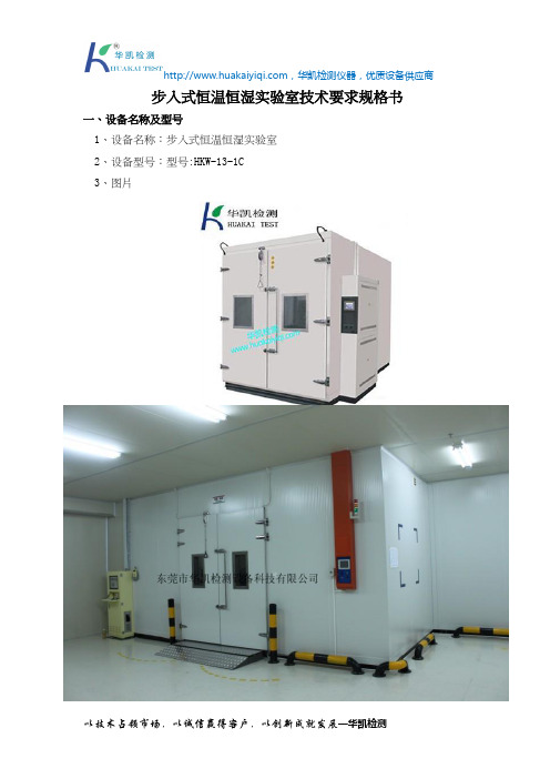
步入式恒温恒湿实验室技术要求规格书一、设备名称及型号1、设备名称:步入式恒温恒湿实验室2、设备型号:型号:HKW-13-1C3、图片(参考图)二、概况1、此设备应符合以下标准要求:GB10589-2008 低温试验箱技术条件GB10592-2008 高低温试验箱技术条件GB10586-2006 湿热试验箱技术条件GB11158-2008 高温试验箱技术条件GB/T5170.2-2008电工电子产品环境试验设备基本参数检定方法温度试验设备GB/T5170.5-2008电工电子产品环境试验设备基本参数检定方法湿热试验设备GB2423.22-2012 电工电子产品基本试验规程试验N:温度变化试验方法GB2423.1-2008 电工电子产品基本试验规程试验A: 低温试验方法GB2423.2-2008电工电子产品基本试验规程试验B: 高温试验方法GB2423.3-2006电工电子产品基本试验规程试验Ca: 恒定湿热试验方法GB2423.4-2008电工电子产品基本试验规程试验Db: 交变湿热试验方法GB2424.1-2015电工电子产品基本环境试验规程试验Db: 高低温试验导则2、设备应具有以下基本特点:1)、试验系统结构设计应先进合理,制造工艺规范,外观美观、大方。
2)、该试验箱主要功能元器件均应采用世界名牌配置(含金量高)、技术原理先进可靠、噪音与节能得到最佳控制。
3)、零部件的配套与组装匹配性好,主要功能元器件均应采用具有国际先进水平的原装进口件,提高了设备的安全性和可靠性,保证用户长时间、高频率的使用要求。
4)、设备应具有良好的操作性、维护性、良好的温度稳定性及持久性、良好的安全性能、不污染环境及危害人身健康。
5)、控制柜内所有电线均应有专用设备打印制作的序号和编号,线路清楚,一目了然。
三、主要技术指标1、室内工作室净空尺寸:长3.0m×宽2.1m×高2.1 m2、外型尺寸:以实际大小为准,箱体门:W1000×H1800mm 双开门门开在3m长方向3、观察窗尺寸:正面2个:宽400×高500 ;4、温度范围:-40℃~ +85℃;5、湿度范围:20%~95% ;6、温、湿度波动度:±1℃;±5%R.H.7、升/降温速率约:升温3.0℃/min 平均 ; 降温 1℃/min 平均8、制冷方式:水冷式9、风速、室内无明显空气对流10、箱体外壳采用库板,外壁采用0.75mm彩钢,内壁采用0.8mm不锈钢。
恒温恒湿箱校验标准

恒温恒湿箱校验标准
一、校验项目及条件
1、校验项目
(1)外观及资料
(2)温度
(3)湿度
2、校验用器具
干湿温度计:分度值0.1℃
二、技术要求
1、湿度大于90%。
2、温度
(1)砼试件:20±3℃
(2)水泥试件:20±1℃
三、校验方法
将试验箱温度显示器上的上限值定为21℃或23℃,下限值定为19℃或17℃,放入干湿温度计,
测试温度显示器上的数值是否与温度计显示一致。
四、校验结果处理
全部校验项目均符合技术要求为合格。
五、校验周期、记录与证书
校验周期为24个月,校验记录格式见下表,校验证书格式见附录Ⅰ。
注意:不同恒温恒湿试验箱校正方法可能稍有偏差,以购买商家提供的校正方法为主。
- 1、下载文档前请自行甄别文档内容的完整性,平台不提供额外的编辑、内容补充、找答案等附加服务。
- 2、"仅部分预览"的文档,不可在线预览部分如存在完整性等问题,可反馈申请退款(可完整预览的文档不适用该条件!)。
- 3、如文档侵犯您的权益,请联系客服反馈,我们会尽快为您处理(人工客服工作时间:9:00-18:30)。
GB11158-1989 高温试验箱技术条件
GB105589-1989 低温试验箱技术条件
GB10586-1989 湿热试验箱技术条件
满足:GB/T2423.1-2001 (IEC68-2-1)试验A 低温试验方法
GB/T2423.2-2001 (IEC68-2-2)试验B 高温试验方法
GJB150.3-1986 高温试验
GJB150.4-1986 低温试验
可程式恒温恒湿试验箱采用高精度微电脑触控式温度及湿度控制,搭配高稳定度的白金测温抵抗体,配合温显度测试的风速循环系统,以达到均匀、准确、稳定的温度、湿度控制。
可程式恒温恒湿试验箱另有完全独立的升温、降温、加湿、冷却除湿系统,可单独作高温、低温及恒温恒湿的不同环境试验。
可程式恒温恒湿试验箱的规格参数
一、适用范围:
1. 温度:-40℃至150℃。
2. 湿度:20%至98%RH。
二、表头控制精度:
1. 温度:±0.3℃
2. 湿度:±2.5%RH
三、表头解析精度:
1. 温度:0.1℃
2. 湿度:0.1%RH
四、加温时间:自常温至100℃,约40分钟。
五、降温时间:自常温至-40℃,约60分钟。
六、机器结构与材质:
1. 内箱尺寸:50cm(W)×60cm(H)×50cm(D)
3. 内箱材质:SUS#304耐热耐寒不锈钢板。
4. 外箱材质:SUS#304高张力不锈钢板,并经多道薄膜游离层表面处理。
5. 保温材质:高密度玻璃棉及高强度PU发泡绝缘材料。
6. 防汗机件:以系统K型管之热能作防汗处理。
7. 门气密材料:高张力parking耐温-90至280℃。
8. 附属设备:
a. 可调式活动盘2只,可任意改变距离。
b. 外接用测试孔乙只,可作动态测试。
c. 广角投射照明设备,采省电高效率日光灯。
d. 多层真空玻璃视窗,防爆型。
e. 附可调固定轴及活动轮4组。
七、冷冻系统及加热系统:
1. 省电型高效率法国泰康压缩机。
2. 采环保R404A冷煤。
3. 全程管路系统氮气加压测漏。
4. 波浪状鳍片型强迫送风冷凝器。
5. 斜率式F I N —T U B E蒸发器。
6. 电磁阀;干燥过滤器等冷冻元件。
7. 内螺旋式K —T Y P E冷媒铜管。
8. U —T Y P E高速电热管,加热迅速。
9. 加温、降温系统完全独立,不需手动控制。
八、加湿及除湿系统:
1. 采用电子并立方式微动加湿系统,附二只磁簧开关,可减少因电子式而産生错误动作。
2. 加湿筒采整座不锈钢制成。
3. 采蒸发器盘管露点温度(ADP)层流接触除湿方式。
4. 附过热、溢流双重保护装置,可安心使用。
5. 加湿、除湿系统完全独立。
6. 供应加湿筒水应尽量采纯水或RO逆渗透水。
九、送风循坏系统:
1. 采多翼离心式循坏风扇,加强轴心加耐高低温之旋转叶片铝合金制成,以达强制对流。
2. FLOW THROW送风方式;水平扩散垂直热交换弧形循环。
3. 可调式侧吹出风口及护纲回风口。
十、电路控制系统:TEMI 880控制器
a. 程序储存容量120组(每种模式最大99步)
b. 采用韩国大型液晶触摸屏LCD中英文文字与数据资料银幕显示交谈方式。
c. 可记忆多组程序(PTN),而各组程序(PTN)可反复循环执行。
d. 微电脑全自动PID+SSR控制方式,既方便又隐定。
e. 温度,湿度可做自动控制,且各组程序可相互连结(LINK)执行。
f. 微电脑智能型多功能控制,具有各组冷冻压缩机、电磁阀、加温HEATER、加湿HEATER….等全自动控制输出功能。
g. 各系统的主要元件配件备有安全检知界面装置,当异常故障发生时,立即切断电源。
十一、安全保护系统:
1. 系统控制回路保险丝。
2. 附有无熔丝保护开关。
3. 超温、断水过热保护开关。
4. 冷冻压缩机过负载保护装置。
5. 系统过电流保护装置。
6. 故障指示灯。
7. 控制器设定错误故障显示及警示。
十二、电源:三相AC220V MAX 40A 50Hz。
