eNSP实验:BGP-MPLS-VPN
华为BGPMPLS IP VPN QoS示例(网络侧为TE隧道)
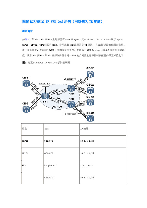
配置BGP/MPLS IP VPN QoS示例(网络侧为TE隧道)组网需求如图1,在PE1、PE2和PE3上均部署有vpna和vpnb,其中CE-11、CE-12、CE-13属于vpna;CE-21、CE-22、CE-23属于vpnb。
公网承载VPN流量的是TE隧道,且TE隧道没有配置带宽值。
由于业务需要,要限制L3VPN公网侧流量的带宽。
配置基于VPN Instance的QoS来限制带宽峰值,使从PE1到PE2和PE3两部分的属于同一VPN的公网流量总和控制在配置的带宽峰值之下。
图1 配置BGP/MPLS IP VPN QoS示例组网图配置思路采用如下的思路配置BGP/MPLS IP VPN QoS(网络侧为TE隧道):1.配置BGP/MPLS IP VPN。
2.对VPN应用隧道策略,使得VPN流量通过TE隧道来承载。
3.为vpna配置基于VPN Instance的QoS。
4.为vpnb配置基于VPN Instance的QoS。
数据准备为完成此配置例,需准备如下的数据:∙VPN实例的名称、RD及VPN-Target∙隧道策略名称以及TE隧道接口∙VPN实例的承诺信息速率∙VPN实例的突发信息速率操作步骤1.MPLS骨干网上配置IGP,使PE之间能学习到各自的Loopback路由。
这里以配置OSPF为例,具体配置过程请参见后面的配置文件配置完成后,PE上执行命令display ip routing-table protocol ospf可以看到PE之间通过OSPF学到了其他PE的Loopback接口路由。
<PE1> display ip routing-table protocol ospfRoute Flags: R - relay, D - download to fib------------------------------------------------------------------------------Public routing table : OSPFDestinations : 5 Routes : 5OSPF routing table status :<Active>Destinations : 2 Routes : 2Destination/Mask Proto Pre Cost Flags NextHop Interface2.2.2.9/32 OSPF 10 1 D 172.1.1.2Pos2/0/13.3.3.9/32 OSPF 10 1 D 172.2.1.2Pos2/0/2OSPF routing table status : <Inactive>Destinations : 3 Routes : 3Destination/Mask Proto Pre Cost Flags NextHop Interface1.1.1.9/32 OSPF 10 0 1.1.1.9LoopBack1172.1.1.0/24 OSPF 10 1 172.1.1.1 Pos2/0/1172.2.1.0/24 OSPF 10 1 172.2.1.1 Pos2/0/22.PE之间建立MP-IBGP对等体# 配置PE1。
BGP MPLS VPN综合实验
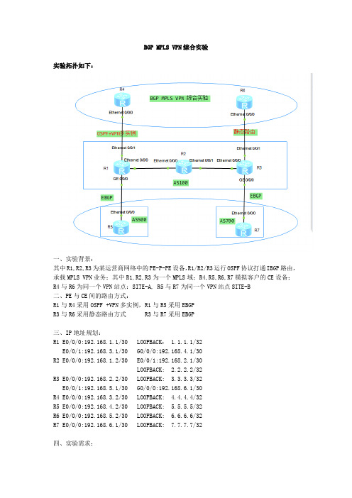
BGP MPLS VPN综合实验实验拓扑如下:一、实验背景:其中R1,R2,R3为某运营商网络中的PE-P-PE设备,R1/R2/R3运行OSPF协议打通IBGP路由,承载MPLS VPN业务;其中R1,R2,R3为一个MPLS域;R4,R5,R6,R7模拟客户的CE设备;R4与R6为同一个VPN站点:SITE-A, R5与R7为同一个VPN站点SITE-B二、PE与CE间的路由方式:R1与R4采用OSPF +VPN多实例,R1与R5采用EBGPR3与R6采用静态路由方式 R3与R7采用EBGP三、IP地址规划:R1 E0/0/0:192.168.1.1/30 LOOPBACK: 1.1.1.1/32E0/0/1:192.168.3.1/30 G0/0/0:192.168.4.1/30R2 E0/0/0:192.168.1.2/30 E0/0/1:192.168.2.1/30LOOPBACK: 2.2.2.2/32R3 E0/0/0:192.168.2.2/30 LOOPBACK: 3.3.3.3/32E0/0/1:192.168.5.1/30 G0/0/0:192.168.6.1/30R4 E0/0/0:192.168.3.2/30 LOOPBACK: 4.4.4.4/32R5 E0/0/0:192.168.4.2/30 LOOPBACK: 5.5.5.5/32R6 E0/0/0:192.168.5.2/30 LOOPBACK: 6.6.6.6/32R7 E0/0/0:192.168.6.1/30 LOOPBACK: 7.7.7.7/32四、实验需求:按照要求完成本实验,业务验证:同一VPN站点的CE能够互访;并能够熟练掌握查看VPN 路由信息;配置步骤:1.首先配置各设备的IP地址(略)2.完成R1-R2-R3之间的OSPF配置;R1ospf 1area 0.0.0.0network 192.168.1.0 0.0.0.3network 1.1.1.1 0.0.0.0R2ospf 1area 0.0.0.0network 192.168.1.0 0.0.0.3network 2.2.2.2 0.0.0.0network 192.168.2.0 0.0.0.3R3ospf 1area 0.0.0.0network 192.168.2.0 0.0.0.3network 3.3.3.3 0.0.0.03.完成R1-R3的IBGP配置R1bgp 100peer 3.3.3.3 as-number 100peer 3.3.3.3 connect-interface LoopBack0#ipv4-family unicastundo synchronizationpeer 3.3.3.3 enableR3bgp 100peer 1.1.1.1 as-number 100peer 1.1.1.1 connect-interface LoopBack0#ipv4-family unicastundo synchronizationpeer 1.1.1.1 enable注解:由于这里BGP承载的业务为MPLS VPN业务,R1-R3之间不必要建立IBGP邻居,只是为了方便大家类似学习配置BGP VPNV4 PEER,所以我们开始配置BGP VPN PEERR1:ipv4-family vpnv4policy vpn-targetpeer 3.3.3.3 enableR3:ipv4-family vpnv4policy vpn-targetpeer 1.1.1.1 enable配置完成后要查看BGP VPNV4 PEER的建立情况,查看的命令如下:[R1-bgp]display bgp vpnv4 all peerBGP local router ID : 192.168.1.1Local AS number : 100Total number of peers : 1 Peers in established state : 1Peer V AS MsgRcvd MsgSent OutQ Up/Down State PrefRcv3.3.3.3 4 100 200 201 0 03:18:14 Established4.完成PE与CE(R1-R5)之间的VPN配置;在R1上创建VPN实例(VRF)ip vpn-instance site-aipv4-familyroute-distinguisher 20:20vpn-target 10:10 export-extcommunityvpn-target 10:10 import-extcommunity#ip vpn-instance site-bipv4-familyroute-distinguisher 30:30vpn-target 40:40 export-extcommunityvpn-target 40:40 import-extcommunity在端口进行绑定VPN实例:interface GigabitEthernet0/0/0ip binding vpn-instance site-bip address 192.168.4.1 255.255.255.252注意事项一:当配置上IP地址绑定VPN实例后,interface GigabitEthernet0/0/0ip binding vpn-instance site-bInfo: All IPv4 related configurations on this interface are removed!提示IPV4地址全部清除,这时我们需要重新配置,删除后也是,切记!interface GigabitEthernet0/0/0ip binding vpn-instance site-bip address 192.168.4.1 255.255.255.252注意事项二:在VPN里我们做ping测试的时候,需要带上vpn实例名字才能ping通,不带的话ping不通的;[R1]ping 192.168.4.2PING 192.168.4.2: 56 data bytes, press CTRL_C to breakRequest time outRequest time outRequest time out正确的PING测试为:[R1]ping -vpn-instance site-b 192.168.4.2PING 192.168.4.2: 56 data bytes, press CTRL_C to breakReply from 192.168.4.2: bytes=56 Sequence=1 ttl=255 time=80 msReply from 192.168.4.2: bytes=56 Sequence=2 ttl=255 time=40 msReply from 192.168.4.2: bytes=56 Sequence=3 ttl=255 time=30 msReply from 192.168.4.2: bytes=56 Sequence=4 ttl=255 time=40 ms5.完成PE与CE(R1-R5)之间的EBGP配置;R1:bgp 100ipv4-family vpn-instance site-bpeer 192.168.4.2 as-number 500R5bgp 500peer 192.168.4.1 as-number 100#ipv4-family unicastundo synchronizationpeer 192.168.4.1 enable查看BGP VPNV4 PEER建立成功与否:[R1-bgp]display bgp vpnv4 all peerBGP local router ID : 192.168.1.1Local AS number : 100Total number of peers : 2 Peers in established state : 2Peer V AS MsgRcvd MsgSent OutQ Up/Down State PrefRcv 3.3.3.3 4 100 260 261 0 04:18:38 Established 0Peer of IPv4-family for vpn instance :VPN-Instance site-b, Router ID 192.168.1.1:192.168.4.2 4 500 3 2 0 00:00:03 Established 1 或者直接带上VPN实例名字查看[R1-bgp]display bgp vpnv4 vpn-instance site-b peerBGP local router ID : 192.168.1.1Local AS number : 100VPN-Instance site-b, Router ID 192.168.1.1:Total number of peers : 1 Peers in established state : 1Peer V AS MsgRcvd MsgSent OutQ Up/Down State PrefRcv192.168.4.2 4 500 10 9 0 00:07:08 Established 1现在我们将R5的loopback地址给宣告出去,不采用import的方式;R5bgp 500network 5.5.5.5 255.255.255.255宣告后我们在R1上进行查看是否学习到:[R1-bgp]display bgp vpnv4 all routing-tableBGP Local router ID is 192.168.1.1Status codes: * - valid, > - best, d - damped,h - history, i - internal, s - suppressed, S - StaleOrigin : i - IGP, e - EGP, ? - incompleteTotal number of routes from all PE: 1Route Distinguisher: 30:30Network NextHop MED LocPrf PrefVal Path/Ogn *> 5.5.5.5/32 192.168.4.2 0 0 500iVPN-Instance site-b, Router ID 192.168.1.1:Total Number of Routes: 1Network NextHop MED LocPrf PrefVal Path/Ogn *> 5.5.5.5/32 192.168.4.2 0 0 500i我们在R3上看看能不能学习到:<R3>display bgp vpnv4 all routing-table<R3>通过查看发现R3学习不到关于5.5.5.5这条BGP VPN路由;在思科设备里这时就应该能够学习到此条路由,但在华为设备里,必须要开启MPLS后才能学到,大家可以做个不带VPN的实验看看;6.开启R1--R2 --R3 MPLS域;R1mpls lsr-id 1.1.1.1mplsmpls ldp#interface Ethernet0/0/0ip address 192.168.1.1 255.255.255.252mplsmpls ldpR2:mpls lsr-id 2.2.2.2mplsmpls ldp#interface Ethernet0/0/0mplsmpls ldp#interface Ethernet0/0/1mplsmpls ldpR3:MPLS LSR 3.3.3.3MPLSMPLS LDP#[R3]interface Ethernet0/0/0[R3-Ethernet0/0/0]mpls[R3-Ethernet0/0/0]mpls ldp然后在R3上查看关于5.5.5.5这条路由信息:[R3]display bgp vpnv4 all routing-tableBGP Local router ID is 192.168.2.2Status codes: * - valid, > - best, d - damped,h - history, i - internal, s - suppressed, S - StaleOrigin : i - IGP, e - EGP, ? - incompleteTotal number of routes from all PE: 1Route Distinguisher: 30:30Network NextHop MED LocPrf PrefVal Path/Ogn *>i 5.5.5.5/32 1.1.1.1 0 100 0 500iVPN-Instance site-b, Router ID 192.168.2.2:Total Number of Routes: 1Network NextHop MED LocPrf PrefVal Path/Ogn *>i 5.5.5.5/32 1.1.1.1 0 100 0 500i 7.完成R3—R7之间的配置(略)配置完成后,在R3上查看BGP VPNV4路由[R3]display bgp vpnv4 all routing-tableBGP Local router ID is 192.168.2.2Status codes: * - valid, > - best, d - damped,h - history, i - internal, s - suppressed, S - StaleOrigin : i - IGP, e - EGP, ? - incompleteTotal number of routes from all PE: 2Route Distinguisher: 30:30Network NextHop MED LocPrf PrefVal Path/Ogn *>i 5.5.5.5/32 1.1.1.1 0 100 0 500i*> 7.7.7.7/32 192.168.6.2 0 0 700iVPN-Instance site-b, Router ID 192.168.2.2:Total Number of Routes: 2Network NextHop MED LocPrf PrefVal Path/Ogn*>i 5.5.5.5/32 1.1.1.1 0 100 0 500i*> 7.7.7.7/32 192.168.6.2 0 0 700i在R7上进行ping测试ping 5.5.5.5[R7-bgp]ping 5.5.5.5PING 5.5.5.5: 56 data bytes, press CTRL_C to breakRequest time outRequest time out--- 5.5.5.5 ping statistics ---2 packet(s) transmitted0 packet(s) received100.00% packet loss通过测试发现PING 5.5.5.5不通,带上源地址ping 却能通;[R7-bgp]ping -a 7.7.7.7 5.5.5.5PING 5.5.5.5: 56 data bytes, press CTRL_C to breakReply from 5.5.5.5: bytes=56 Sequence=1 ttl=253 time=210 msReply from 5.5.5.5: bytes=56 Sequence=2 ttl=253 time=110 msReply from 5.5.5.5: bytes=56 Sequence=3 ttl=253 time=170 msReply from 5.5.5.5: bytes=56 Sequence=4 ttl=253 time=110 msReply from 5.5.5.5: bytes=56 Sequence=5 ttl=253 time=100 ms--- 5.5.5.5 ping statistics ---5 packet(s) transmitted5 packet(s) received0.00% packet lossround-trip min/avg/max = 100/140/210 ms<R5>ping -a 5.5.5.5 7.7.7.7PING 7.7.7.7: 56 data bytes, press CTRL_C to breakReply from 7.7.7.7: bytes=56 Sequence=1 ttl=253 time=130 msReply from 7.7.7.7: bytes=56 Sequence=2 ttl=253 time=80 msReply from 7.7.7.7: bytes=56 Sequence=3 ttl=253 time=110 ms--- 7.7.7.7 ping statistics ---3 packet(s) transmitted3 packet(s) received0.00% packet lossround-trip min/avg/max = 80/106/130 ms这是为什么呢?因为我们直接PING 的话是相当于带着源地址为接口地址PING的,由于接口IP地址和5.5.5.5路由不通;那么怎么办呢?这时候就需要把直连vpn的接口的路由给发布出去,我们在R1上可以做network也可以做import方式;在现网实际操作中会有很多路由地址段需要发布,我们假如要做的话就需要手工的方式进行network,工作量较大,这里我们采用import的方式进行引入;[R1]bgp 100[R1-bgp] ipv4-family vpn-instance site-b[R1-bgp-site-b]import-route direct[R3]bgp 100[R3-bgp] ipv4-family vpn-instance site-b[R3-bgp-site-b]import-route direct另附上network的方式:[R1]bgp 100ipv4-family vpn-instance site-bnetwork 192.168.4.0 255.255.255.252peer 192.168.4.2 as-number 500[R3]bgp 100ipv4-family vpn-instance site-bnetwork 192.168.6.0 255.255.255.252peer 192.168.6.2 as-number 700做完之后我们可以PING测试下:[R1]ping -vpn-instance site-b 192.168.6.1PING 192.168.6.1: 56 data bytes, press CTRL_C to breakReply from 192.168.6.1: bytes=56 Sequence=1 ttl=254 time=100 ms Reply from 192.168.6.1: bytes=56 Sequence=2 ttl=254 time=50 ms Reply from 192.168.6.1: bytes=56 Sequence=3 ttl=254 time=60 ms Reply from 192.168.6.1: bytes=56 Sequence=4 ttl=254 time=70 ms Reply from 192.168.6.1: bytes=56 Sequence=5 ttl=254 time=80 ms --- 192.168.6.1 ping statistics ---5 packet(s) transmitted5 packet(s) received0.00% packet lossround-trip min/avg/max = 50/72/100 ms[R1]ping -vpn-instance site-b 5.5.5.5PING 5.5.5.5: 56 data bytes, press CTRL_C to breakReply from 5.5.5.5: bytes=56 Sequence=1 ttl=255 time=30 ms Reply from 5.5.5.5: bytes=56 Sequence=2 ttl=255 time=60 ms Reply from 5.5.5.5: bytes=56 Sequence=3 ttl=255 time=30 ms--- 5.5.5.5 ping statistics ---3 packet(s) transmitted3 packet(s) received0.00% packet lossround-trip min/avg/max = 30/40/60 ms[R1]ping -vpn-instance site-b 7.7.7.7PING 7.7.7.7: 56 data bytes, press CTRL_C to breakReply from 7.7.7.7: bytes=56 Sequence=1 ttl=254 time=130 msReply from 7.7.7.7: bytes=56 Sequence=2 ttl=254 time=90 msReply from 7.7.7.7: bytes=56 Sequence=3 ttl=254 time=60 msReply from 7.7.7.7: bytes=56 Sequence=4 ttl=254 time=130 msReply from 7.7.7.7: bytes=56 Sequence=5 ttl=254 time=70 ms--- 7.7.7.7 ping statistics ---5 packet(s) transmitted5 packet(s) received0.00% packet lossround-trip min/avg/max = 60/96/130 ms[R5]ping 7.7.7.7PING 7.7.7.7: 56 data bytes, press CTRL_C to breakReply from 7.7.7.7: bytes=56 Sequence=1 ttl=253 time=110 msReply from 7.7.7.7: bytes=56 Sequence=2 ttl=253 time=70 msReply from 7.7.7.7: bytes=56 Sequence=3 ttl=253 time=90 msReply from 7.7.7.7: bytes=56 Sequence=4 ttl=253 time=100 msReply from 7.7.7.7: bytes=56 Sequence=5 ttl=253 time=110 ms--- 7.7.7.7 ping statistics ---5 packet(s) transmitted5 packet(s) received0.00% packet lossround-trip min/avg/max = 70/96/110 ms7.完成R1—R4之间的配置(略)[R1-ospf-2]dis this#ospf 2 vpn-instance site-aarea 0.0.0.0network 192.168.3.0 0.0.0.38.<r4>dis c c ospf#ospf 2area 0.0.0.0network 192.168.3.0 0.0.0.3network 4.4.4.4 0.0.0.0同理在R1做完后需要将OSPF路由引入到BGP VPN实例中,生成BGP VPNV4路由信息:[R1]bgp 100ipv4-family vpn-instance site-aimport-route ospf 2引入之后我们在R1上查看关于R4的BGP VPNV4 路由[R1-bgp-site-a]display bgp vpnv4 vpn-instance site-a routing-tableBGP Local router ID is 192.168.1.1Status codes: * - valid, > - best, d - damped,h - history, i - internal, s - suppressed, S - StaleOrigin : i - IGP, e - EGP, ? - incompleteVPN-Instance site-a, Router ID 192.168.1.1:Total Number of Routes: 2Network NextHop MED LocPrf PrefVal Path/Ogn*> 4.4.4.4/32 0.0.0.0 2 0 ?*> 192.168.3.0/30 0.0.0.0 0 0 ?从这里我们能看到R1学习到了R4的路由(其中包含4.4.4.4和互联接口),并生成了BGP VPNV4路由信息;9.完成R3—R6之间的配置(static路由方式)在R3上指示静态路由方式打通VPNV4 路由;[R3]ip route-static vpn-instance site-a 6.6.6.6 255.255.255.255 192.168.5.2配置完成后在R3上应该能看到关于6.6.6.6的vpnv4路由[R3]display ip routing-table vpn-instance site-aRoute Flags: R - relay, D - download to fib------------------------------------------------------------------------------Routing Tables: site-aDestinations : 3 Routes : 3Destination/Mask Proto Pre Cost Flags NextHop Interface6.6.6.6/32 Static 60 0 RD 192.168.5.2 Ethernet0/0/1192.168.5.0/30 Direct 0 0 D 192.168.5.1 Ethernet0/0/1192.168.5.1/32 Direct 0 0 D 127.0.0.1 Ethernet0/0/1然后在R3上将这条路由变成BGP VPNV4路由;[R3]BGP 100ipv4-family vpn-instance site-aimport-route static完成后在R3上就能看见关于R6的bgp vpnv4路由信息;[R3-bgp-site-a]display bgp vpnv4 vpn-instance site-a routing-tableBGP Local router ID is 192.168.2.2Status codes: * - valid, > - best, d - damped,h - history, i - internal, s - suppressed, S - StaleOrigin : i - IGP, e - EGP, ? - incompleteVPN-Instance site-a, Router ID 192.168.2.2:Total Number of Routes: 3Network NextHop MED LocPrf PrefVal Path/Ogn*>i 4.4.4.4/32 1.1.1.1 2 100 0 ?*> 6.6.6.6/32 0.0.0.0 0 0 ?*>i 192.168.3.0/30 1.1.1.1 0 100 0 ?我们查看路由表,发现有R4的loopback地址和互联接口的BGP VPNV4路由,及R6的loopback地址路由,但是没有R6的互联地址的路由,这样的话会导致R6的路由出不去?这样的话,我们就将R6的路由也发布下,我们也可以采用network或者import的方式发布;我们来采用import的方式![R3]bgp 100ipv4-family vpn-instance site-aimport-route direct引入后我们来查看路由表:[R3-bgp]display bgp vpnv4 vpn-instance site-a routing-tableBGP Local router ID is 192.168.2.2Status codes: * - valid, > - best, d - damped,h - history, i - internal, s - suppressed, S - StaleOrigin : i - IGP, e - EGP, ? - incompleteVPN-Instance site-a, Router ID 192.168.2.2:Total Number of Routes: 5Network NextHop MED LocPrf PrefVal Path/Ogn*>i 4.4.4.4/32 1.1.1.1 2 100 0 ?*> 6.6.6.6/32 0.0.0.0 0 0 ?*>i 192.168.3.0/30 1.1.1.1 0 100 0 ?*> 192.168.5.0/30 0.0.0.0 0 0 ?*> 192.168.5.1/32 0.0.0.0 0 0 ?引入后就多了R3与R6的互联地址路由信息;那么在R6上我们需要做什么呢?那就是指导路由出去,匹配网关,也就是做条缺省路由;[R6] ip route-static 0.0.0.0 0.0.0.0 192.168.5.1做完以上所有的配置后,VPN之间就都能够互访了;完整配置如下:实验背景,在全国运营商中,有很多ISP基于P设备(P/PE设备一般来说都是NE5000E)的造价以及传输资源等一系列因素,可能就会放弃P设备的购买,把PE兼顾P设备进行使用;本实验就把P设备去除,用R1和R3来模拟P/PE设备;更新IP地址:R3:E0/0/0:192.168.1.2/30实验拓扑如下:然后在R3的接口上开启MPLS后,其它配置不变;实验背景:在运营商承载网里的PE-CE组网,有部分运营商采用S9300系列交换机作为CE,交换机采用静态或者动态路由协议方式打通路由在本实验中R1与R3之间的配置不变,R1与SW1采用OSPF+VPN方式打通VPNV4路由,R3与SW2采用静态路由的方式打通路由,此时R3的角色为PE兼CE,交换机就作为PC的三层网关设备;IP地址规划:R1 E0/0/1:192.168.3.1/24SW1 G0/0/1透传VLAN 4000 VLANIF4000:192.168.3.2/24PC1: 192.168.3.100/24R3 E0/0/1:192.168.5.1/24SW2 G0/0/1透传VLAN 4000 VLANIF4000:192.168.5.2/24PC2的VLAN:VLAN 10 网关VLANIF10IP:10.10.10.1/24PC2:10.10.10.100/24完整配置如附件。
华为路由器MPLS-VPN配置示例

华为路由器M P L S-V P N配置示例-CAL-FENGHAI-(2020YEAR-YICAI)_JINGBIAN配置BGP/MPLS IP VPN示例图1 配置BGP/MPLS IP VPN组网图组网需求配置思路操作步骤配置文件组网需求如图1所示:CE1连接公司总部研发区、CE3连接分支机构研发区,CE1和CE3属于vpna;CE2连接公司总部非研发区、CE4连接分支机构非研发区,CE2和CE4属于vpnb。
公司要求通过部署BGP/MPLS IP VPN,实现总部和分支机构的安全互通,同时要求研发区和非研发区间数据隔离。
配置思路采用如下的思路配置BGP/MPLS IP VPN:1.P、PE之间配置OSPF,实现骨干网的IP连通性。
2.PE、P上配置MPLS基本能力和MPLS LDP,建立MPLS LSP公网隧道,传输VPN数据。
3.PE1和PE2上配置VPN实例,其中,vpna使用的VPN-target属性为111:1,vpnb使用的VPN-target属性为222:2,以实现相同VPN间互通,不同VPN间隔离。
同时,与CE相连的接口和相应的VPN实例绑定,以接入VPN用户。
4.PE1和PE2之间配置MP-IBGP,交换VPN路由信息。
5.CE与PE之间配置EBGP,交换VPN路由信息。
操作步骤1.在MPLS骨干网上配置OSPF协议,实现骨干网PE和P的互通# 配置PE1。
<Huawei> system-view[Huawei] sysname PE1[PE1] interface loopback 1[PE1-LoopBack1] ip address 1.1.1.9 32[PE1-LoopBack1] quit[PE1] interface gigabitethernet 3/0/0[PE1-GigabitEthernet3/0/0] ip address 172.1.1.1 24[PE1-GigabitEthernet3/0/0] quit[PE1] ospf 1[PE1-ospf-1] area 0[PE1-ospf-1-area-0.0.0.0] network 172.1.1.0 0.0.0.255[PE1-ospf-1-area-0.0.0.0] network 1.1.1.9 0.0.0.0[PE1-ospf-1-area-0.0.0.0] quit[PE1-ospf-1] quit# 配置P。
juniper-OSPF-BGP-ISIS-MPLS_VPN_实验
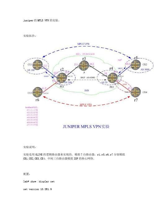
set logical-systems r3 interfaces em3 unit 34 family mpls set logical-systems r3 interfaces lo0 unit 3 family inet address 3.3.3.3/32 set logical-systems r3 interfaces lo0 unit 3 family iso address 47.0000.0000.0003.00 set logical-systems r3 protocols mpls interface em3.1 set logical-systems r3 protocols mpls interface em3.34 set logical-systems r3 protocols isis interface em3.1 set logical-systems r3 protocols isis interface em3.34 set logical-systems r3 protocols isis interface lo0.3 set logical-systems r3 protocols ospf area 0.0.0.0 interface em3.1 set logical-systems r3 protocols ospf area 0.0.0.0 interface em3.34 set logical-systems r3 protocols ospf area 0.0.0.0 interface lo0.3 set logical-systems r3 protocols ldp interface all set logical-systems r3 routing-options router-id 3.3.3.3 set logical-systems r4 interfaces em4 unit 34 vlan-id 34 set logical-systems r4 interfaces em4 unit 34 family inet address 34.1.1.4/24 set logical-systems r4 interfaces em4 unit 34 family iso set logical-systems r4 interfaces em4 unit 34 family mpls set logical-systems r4 interfaces em4 unit 45 vlan-id 45 set logical-systems r4 interfaces em4 unit 45 family inet address 45.1.1.4/24 set logical-systems r4 interfaces em4 unit 45 family mpls set logical-systems r4 interfaces em4 unit 47 vlan-id 47 set logical-systems r4 interfaces em4 unit 47 family inet address 47.1.1.4/24 set logical-systems r4 interfaces lo0 unit 4 family inet address 4.4.4.4/32
MPLS BGP VPN详解

MPLS BGP VPN 配置详解一、组网图如下:二、配置过程概述:1.PE-1、P、PE-2之间配置IGP(OSPF为例)2.PE-1、P、PE-2之间起MPLS3.PE-1和PE-2上做两个VPN实例:vpna、vpnb;CE-1、CE-3属于 vpna,CE-2、CE-4属于vpnb4.PE-1和PE-2之间建MP-BGP5.PE和CE之间起路由(PE-1和CE-1 EBGP;PE-1和CE-2 静态;PE-2和CE-3 OSPF;PE-2和CE-4 RIP)6.配置完成后,CE-1和CE-3可以互通;CE-2和CE-4可以互通三、端口对照表:设备名称端口名称IP地址描述P LoopBack0 2.2.2.2/32Ethernet2/0 100.0.0.2/30 TO-PE-1 Ethernet2/1 200.0.0.1/30 TO-PE-2PE-1 LoopBack0 1.1.1.1/32Ethernet0/0 192.168.1.1/24 TO-CE-1 Ethernet0/1 192.168.2.1/24 TO-CE-2 Ethernet3/0 100.0.0.1 TO-PPE-2 LoopBack0 3.3.3.3/32四、具体步骤:1.PE-1、P、PE-2之间起OSPF(一定要把loopback0的地址发布出去)<PE-1>ospf 1area 0.0.0.0network 1.1.1.1 0.0.0.0network 100.0.0.0 0.0.0.3<PE-2>ospf 1area 0.0.0.0network 3.3.3.3 0.0.0.0network 200.0.0.0 0.0.0.3<P>ospf 1area 0.0.0.0network 2.2.2.2 0.0.0.0network 100.0.0.0 0.0.0.3network 200.0.0.0 0.0.0.3配置完后,在P上查看OSPF邻居状态,和两个PE的邻居状态显示状态为:Full <P>dis ospf peerOSPF Process 1 with Router ID 2.2.2.2NeighborsArea 0.0.0.0 interface 200.0.0.1(Ethernet2/1)'s neighbor(s)RouterID: 3.3.3.3 Address: 200.0.0.2State: Full Mode: Nbr is Master Priority: 1DR: 200.0.0.2 BDR: 200.0.0.1Dead timer expires in 38sNeighbor has been up for 02:11:32Area 0.0.0.0 interface 100.0.0.2(Ethernet2/0)'s neighbor(s)RouterID: 1.1.1.1 Address: 100.0.0.1State: Full Mode: Nbr is Slave Priority: 1DR: 100.0.0.2 BDR: 100.0.0.1Dead timer expires in 31sNeighbor has been up for 02:10:462.PE-1、P、PE-2之间起MPLS(mpls只需要在P和两个PE的互联接口启用)<PE-1>mpls#mpls ldp#interface Ethernet3/0description TO-Pip address 100.0.0.1 255.255.255.252mplsmpls ldp enable<PE-2>mpls#mpls ldp#interface Ethernet3/0description TO-Pip address 200.0.0.2 255.255.255.252mplsmpls ldp enable<P>mpls#mpls ldp#interface Ethernet2/0description TO-PE-1ip address 100.0.0.2 255.255.255.252mplsmpls ldp enable#interface Ethernet2/1description TO-PE-2ip address 200.0.0.1 255.255.255.252mplsmpls ldp enable#配置完后,在P上查看和两个PE的MPLS LDP的状态为:Operational dis mpls ldp sessionDisplaying information about all sessions:Local LDP ID: 2.2.2.2:0; Peer LDP ID: 1.1.1.1:0TCP Connection: 2.2.2.2 -> 1.1.1.1Session State: OperationalSession Role: ActiveSession existed time: 2 hours 8 minutes 27 secondsBasic Hello Packets Sent/Received: 1948/1947KeepAlive Packets Sent/Received: 325/325Negotiated Keepalive hold time: 60 Peer PV Limit: 0LDP Basic Discovery Source((A) means active):Ethernet2/0(A)Local LDP ID: 2.2.2.2:0; Peer LDP ID: 3.3.3.3:0TCP Connection: 2.2.2.2 <- 3.3.3.3Session State: OperationalSession Role: PassiveSession existed time: 2 hours 7 minutes 45 secondsBasic Hello Packets Sent/Received: 1944/1937KeepAlive Packets Sent/Received: 323/323Negotiated Keepalive hold time: 60 Peer PV Limit: 0LDP Basic Discovery Source((A) means active):Ethernet2/1(A)3.PE-1和PE-2上做两个VPN实例:(vpna、vpnb;CE-1、CE-3属于 vpna,CE-2、CE-4属于vpnb )<PE-1>ip vpn-instance vpnaroute-distinguisher 100:1vpn-target 100:1 export-extcommunityvpn-target 100:1 import-extcommunity#ip vpn-instance vpnbroute-distinguisher 200:1vpn-target 200:1 export-extcommunityvpn-target 200:1 import-extcommunity#interface Ethernet0/0description TO-CE-1ip binding vpn-instance vpnaip address 192.168.1.1 255.255.255.0#interface Ethernet0/1description TO-CE-2ip binding vpn-instance vpnbip address 192.168.2.1 255.255.255.0#PE-1检查VPN实例配置dis ip vpn-instance vpnaVPN-Instance : vpnaNo descriptionRoute-Distinguisher : 100:1Interfaces :Ethernet0/0dis ip vpn-instance vpnbVPN-Instance : vpnbNo descriptionRoute-Distinguisher : 200:1Interfaces :Ethernet0/1<PE-2>ip vpn-instance vpnaroute-distinguisher 100:1vpn-target 100:1 export-extcommunity vpn-target 100:1 import-extcommunity #ip vpn-instance vpnbroute-distinguisher 200:1vpn-target 200:1 export-extcommunity vpn-target 200:1 import-extcommunity #interface Ethernet2/0description TO-CE-3ip binding vpn-instance vpnaip address 192.168.3.1 255.255.255.0 #interface Ethernet2/1description TO-CE-4ip binding vpn-instance vpnbip address 192.168.4.1 255.255.255.0 #PE-2上检查VPN实例配置dis ip vpn-instance vpnaVPN-Instance : vpnaNo descriptionRoute-Distinguisher : 100:1Interfaces :Ethernet2/0dis ip vpn-instance vpnbVPN-Instance : vpnbNo descriptionRoute-Distinguisher : 200:1Interfaces :Ethernet2/14.PE-1和PE-2之间建MP-BGP<PE-1>bgp 100undo synchronizationgroup in internalpeer in connect-interface LoopBack0peer 3.3.3.3 group in#ipv4-family vpnv4peer in enablepeer 3.3.3.3 group in#<PE-2>bgp 100undo synchronizationgroup in internalpeer in connect-interface LoopBack0peer 1.1.1.1 group in#ipv4-family vpnv4peer in enablepeer 1.1.1.1 group in#配置完后,检查BGP VPNV4 邻居状态为:Established<PE-1>dis bgp vpnv4 all peerPeer AS-num Ver Queued-Tx Msg-Rx Msg-Tx Up/Down State --------------------------------------------------------------------------------3.3.3.3 100 4 0 14 21 01:38:56 Established 192.168.1.2 65411 4 0 60 64 00:57:32 Established <PE-2>dis bgp vpnv4 all peerPeer AS-num Ver Queued-Tx Msg-Rx Msg-Tx Up/Down State --------------------------------------------------------------------------------1.1.1.1 100 4 0 21 14 01:42:10 Established5.PE和CE之间起路由a.PE-1和CE-1之间建立EBGP<PE-1>bgp 100ipv4-family vpn-instance vpnaimport-route directundo synchronizationgroup out externalpeer out as-number 65411peer 192.168.1.2 group out#<CE-1>bgp 65411network 10.0.0.1 255.255.255.255undo synchronizationgroup out externalpeer out as-number 100peer 192.168.1.1 group out#配置完后,检查BGP邻居状态为:Established<PE-1>dis bgp vpnv4 all peerPeer AS-num Ver Queued-Tx Msg-Rx Msg-Tx Up/Down State --------------------------------------------------------------------------------3.3.3.3 100 4 0 14 21 01:38:56 Established 192.168.1.2 65411 4 0 60 64 00:57:32 EstablishedPE-1上查看vpna路由表<PE-1>dis ip routing-table vpn-instance vpnavpna Route InformationRouting Table: vpna Route-Distinguisher: 100:1Destination/Mask Protocol Pre Cost Nexthop Interface10.0.0.1/32 BGP 256 0 192.168.1.2 Ethernet0/030.0.0.1/32 BGP 256 1563 3.3.3.3 InLoopBack0 192.168.1.0/24 DIRECT 0 0 192.168.1.1 Ethernet0/0192.168.1.1/32 DIRECT 0 0 127.0.0.1 InLoopBack0 192.168.3.0/24 BGP 256 0 3.3.3.3 InLoopBack0*由此可以看到vpna的路由表内,只有关于CE-1和CE-3的路由信息b.PE-1和CE-2之间建立静态路由<PE-1>ip route-static vpn-instance vpnb 20.0.0.1 255.255.255.255 192.168.2.2 preference 60#ipv4-family vpn-instance vpnbimport-route staticimport-route directundo synchronization<CE-2>ip route-static 0.0.0.0 0.0.0.0 192.168.2.1 preference 60配置完后,在PE-1上查看vpnb路由表<PE-1>dis ip routing-table vpn-instance vpnbvpnb Route InformationRouting Table: vpnb Route-Distinguisher: 200:1Destination/Mask Protocol Pre Cost Nexthop Interface20.0.0.1/32 STA TIC 60 0 192.168.2.2 Ethernet0/1 40.0.0.0/8 BGP 256 1 3.3.3.3 InLoopBack0 192.168.2.0/24 DIRECT 0 0 192.168.2.1 Ethernet0/1 192.168.2.1/32 DIRECT 0 0 127.0.0.1 InLoopBack0 192.168.4.0/24 BGP 256 0 3.3.3.3 InLoopBack0 *由此可以看到vpna的路由表内,只有关于CE-2和CE-4的路由信息c.PE-2和CE-3之间建立OSPF<PE-2>ospf 100 vpn-instance vpnaimport-route bgparea 0.0.0.0network 192.168.3.0 0.0.0.255#bgp 100#ipv4-family vpn-instance vpnaimport-route ospf 100import-route directundo synchronization<CE-3>ospfarea 0.0.0.0network 30.0.0.1 0.0.0.0network 192.168.3.0 0.0.0.3配置完后,在PE-2上查看vpna路由表dis ip routing-table vpn-instance vpnavpna Route InformationRouting Table: vpna Route-Distinguisher: 100:1Destination/Mask Protocol Pre Cost Nexthop Interface10.0.0.1/32 BGP 256 0 1.1.1.1 InLoopBack0 30.0.0.1/32 OSPF 10 1563 192.168.3.2 Ethernet2/0 192.168.1.0/24 BGP 256 0 1.1.1.1 InLoopBack0 192.168.3.0/24 DIRECT 0 0 192.168.3.1 Ethernet2/0 192.168.3.1/32 DIRECT 0 0 127.0.0.1 InLoopBack0d.PE-2和CE-4之间建立RIP<PE-2>rip#ipv4-family vpn-instance vpnbnetwork 192.168.4.0import-route bgp#ipv4-family vpn-instance vpnbimport-route directimport-route ripundo synchronization<CE-4>ripnetwork 192.168.4.0network 40.0.0.0配置完后,在PE-2上查看vpnb路由表<PE-2>dis ip routing-table vpn-instance vpnbvpnb Route InformationRouting Table: vpnb Route-Distinguisher: 200:1Destination/Mask Protocol Pre Cost Nexthop Interface20.0.0.1/32 BGP 256 0 1.1.1.1 InLoopBack0 40.0.0.0/8 RIP 100 1 192.168.4.2 Ethernet2/1 192.168.2.0/24 BGP 256 0 1.1.1.1 InLoopBack0 192.168.4.0/24 DIRECT 0 0 192.168.4.1 Ethernet2/1 192.168.4.1/32 DIRECT 0 0 127.0.0.1 InLoopBack0五、测试:<CE-1>dis ip routing-tableRouting Table: public netDestination/Mask Protocol Pre Cost Nexthop Interface10.0.0.1/32 DIRECT 0 0 127.0.0.1 InLoopBack0 30.0.0.1/32 BGP 256 0 192.168.1.1 Ethernet3/0 127.0.0.0/8 DIRECT 0 0 127.0.0.1 InLoopBack0 127.0.0.1/32 DIRECT 0 0 127.0.0.1 InLoopBack0192.168.1.0/24 DIRECT 0 0 192.168.1.2 Ethernet3/0 192.168.1.2/32 DIRECT 0 0 127.0.0.1 InLoopBack0 192.168.3.0/24 BGP 256 0 192.168.1.1 Ethernet3/0<CE-1>ping 30.0.0.1PING 30.0.0.1: 56 data bytes, press CTRL_C to breakReply from 30.0.0.1: bytes=56 Sequence=1 ttl=253 time=11 msReply from 30.0.0.1: bytes=56 Sequence=2 ttl=253 time=10 msReply from 30.0.0.1: bytes=56 Sequence=3 ttl=253 time=6 msReply from 30.0.0.1: bytes=56 Sequence=4 ttl=253 time=11 msReply from 30.0.0.1: bytes=56 Sequence=5 ttl=253 time=16 ms<CE-2><CE-2>dis ip routing-tableRouting Table: public netDestination/Mask Protocol Pre Cost Nexthop Interface0.0.0.0/0 STA TIC 60 0 192.168.2.1 Ethernet2/0 20.0.0.1/32 DIRECT 0 0 127.0.0.1 InLoopBack0 127.0.0.0/8 DIRECT 0 0 127.0.0.1 InLoopBack0 127.0.0.1/32 DIRECT 0 0 127.0.0.1 InLoopBack0 192.168.2.0/24 DIRECT 0 0 192.168.2.2 Ethernet2/0 192.168.2.2/32 DIRECT 0 0 127.0.0.1 InLoopBack0 <CE-2>ping 40.0.0.1PING 40.0.0.1: 56 data bytes, press CTRL_C to breakReply from 40.0.0.1: bytes=56 Sequence=1 ttl=253 time=2 msReply from 40.0.0.1: bytes=56 Sequence=2 ttl=253 time=3 msReply from 40.0.0.1: bytes=56 Sequence=3 ttl=253 time=3 msReply from 40.0.0.1: bytes=56 Sequence=4 ttl=253 time=2 msReply from 40.0.0.1: bytes=56 Sequence=5 ttl=253 time=3 ms<CE-3>dis ip routing-tableRouting Table: public netDestination/Mask Protocol Pre Cost Nexthop Interface10.0.0.1/32 O_ASE 150 1 192.168.3.1 Vlan-interface1 30.0.0.1/32 DIRECT 0 0 127.0.0.1 InLoopBack0 127.0.0.0/8 DIRECT 0 0 127.0.0.1 InLoopBack0 127.0.0.1/32 DIRECT 0 0 127.0.0.1 InLoopBack0 192.168.1.0/24 O_ASE 150 1 192.168.3.1 Vlan-interface1 192.168.3.0/24 DIRECT 0 0 192.168.3.2 Vlan-interface1 192.168.3.2/32 DIRECT 0 0 127.0.0.1 InLoopBack0 <CE-3>ping 10.0.0.1PING 10.0.0.1: 56 data bytes, press CTRL_C to breakReply from 10.0.0.1: bytes=56 Sequence=1 ttl=252 time = 15 msReply from 10.0.0.1: bytes=56 Sequence=2 ttl=252 time = 7 msReply from 10.0.0.1: bytes=56 Sequence=3 ttl=252 time = 7 msReply from 10.0.0.1: bytes=56 Sequence=4 ttl=252 time = 8 msReply from 10.0.0.1: bytes=56 Sequence=5 ttl=252 time = 9 ms<CE-4>dis ip routing-tableRouting Table: public netDestination/Mask Protocol Pre Cost Nexthop Interface20.0.0.0/8 RIP 100 1 192.168.4.1 Ethernet0/1 40.0.0.1/32 DIRECT 0 0 127.0.0.1 InLoopBack0 127.0.0.0/8 DIRECT 0 0 127.0.0.1 InLoopBack0 127.0.0.1/32 DIRECT 0 0 127.0.0.1 InLoopBack0 192.168.2.0/24 RIP 100 1 192.168.4.1 Ethernet0/1 192.168.4.0/24 DIRECT 0 0 192.168.4.2 Ethernet0/1 192.168.4.2/32 DIRECT 0 0 127.0.0.1 InLoopBack0 <CE-4>ping 20.0.0.1PING 20.0.0.1: 56 data bytes, press CTRL_C to breakReply from 20.0.0.1: bytes=56 Sequence=1 ttl=253 time=3 msReply from 20.0.0.1: bytes=56 Sequence=2 ttl=253 time=2 msReply from 20.0.0.1: bytes=56 Sequence=3 ttl=253 time=3 msReply from 20.0.0.1: bytes=56 Sequence=4 ttl=253 time=3 msReply from 20.0.0.1: bytes=56 Sequence=5 ttl=253 time=3 ms。
域内MP BGP实验总结

域内MP BGP /MPLS VPN配置实验总结CE----PE:可运行静态路由、RIPV2、EIGRP、OSPF、EBGP。
PE----P: 只运行MPLS IP即可,PE1—P—PE2在同一路由选择域内(IGP)。
PE1--PE2: 建立MP-IBGP VPNV4邻居关系,传递VPN路由。
所有VRF均配置在PE设备上,CE设备不知道VPN信息。
P:Provider Router PE: Provider Edge Router CE: Customer Edge RouterCE—PE间静态路由CE:无需知道VPN信息,配置一条指向CE—PE间互联链路PE侧接口的缺省路由即可。
CE(config)#ip route 0.0.0.0 0.0.0.0 10.10.12.2PE:在PE上宣告CE站点上存在的私网(VPN)路由即可。
PE(config)#ip route vrf VPNA 1.1.1.1 255.255.255.255 serial 1/0PE(config)#ip route vrf VPNA 172.16.1.1 255.255.255.0 serial 1/0CE—PE间RIPV2路由协议CE:在RIPV2中宣告接口地址的网段;宣告作为VPN私网地址的网段,并将这些接口设置为被动接口(passive-interface)。
CE(config)#router ripversion 2network 10.10.12.1network 1.1.1.1network 172.16.1.1passive-interface loopback 0passive-interface loopback 10 这就是CE所需的全部配置!PE:启动RIPV2协议进程,在ipv4 vrf VPNA地址簇宣告互联接口地址,引入BGP中VRF VPNA 的路由信息。
在BGP的ipv4 vrf VPNA地址簇中引入RIPV2 路由信息。
MPLS vpn配置--私网静态路由

MPLS vpn配置--私网静态路由实验环境:如图,Internet运行OSPF协议使外网互通;两个私网,运行静态路由,与外网建立联系;R2、R4运行扩展IBGP,承载vpn-v4地址族。
配置解析:1、按IP地址配置各接口2、配置PE1-P-PE2 公网路由3、各设备启用ip cefRouter (config)#ip cef4、在PE1-P-PE2主干接口启用mplsPe1(config)#int fa0/1PE1(config-if)#mpls ip5、在PE上创建VRFPE1(config)#ip vrf vpnaPE1(config-vrf)#rd 100:1PE1(config-vrf)#route-target 100:16、将PE上与CE相连的接口加入到VRF中PE1(config)#int fa0/0PE1(CONFIG-IF)#ip vrf forwarding vpnaPE1(config-if)#ip add 192.168.1.1255.255.255.0PE1(config-if)#no shut7、在PE上配置VRF 静态路由PE1(config)#ip route vrf vpna 1.1.1.1 255.255.255.255 192.168.1.1 8、配置PE1、PE2 iBGPPE1(config)#router bgp 100PE1(config-router )#bgp router –id 2.2.2.2PE1(config-router)#nei 4.4.4.4remote-as 100PE1(config-router)#nei 4.4.4.4update lo0PE1(config-router)#no syPE1(config-router)#no auto9、在PE上启用address-familyVPNV4扩展团体属性PE1(config)#router bgp 100PE1(config-router)#address-family vpnv4PE1(config –router )#nei 4.4.4.4actiPE1(config –router )#nei 4.4.4.4send-community ex10、在PE上启用address-familyvrf ipv4 vpnaPE1(config)#router bgp 100PE1(config-router)#address-family ipv4 vrfvpnaPE1(config-router-af)#no syPE1(config-router-af)#no auto将静态路由重分布到address-familyipv4 vrf vpna中PE1(config-router-af)#redis static11、配置CE间的静态路由CE1(config)#ip route 5.5.5.5255.255.255.255 192.168.1.2配置步骤:R1#sh run!hostname R1!ip cef!interface Loopback0ip address 1.1.1.1 255.255.255.255!interface Ethernet0/0ip address 192.168.1.1 255.255.255.0!no ip http serverno ip http secure-serverip route 5.5.5.5 255.255.255.255 192.168.1.2R2#sh run!hostname R2!ip cef!ip vrf vpnard 100:1route-target export 100:1route-target import 100:1!interface Loopback0ip address 2.2.2.2 255.255.255.255!interface Ethernet0/0ip vrf forwarding vpnaip address 192.168.1.2 255.255.255.0!interface Ethernet0/1ip address 100.1.1.1 255.255.255.252mpls ip!router ospf 1network 2.2.2.2 0.0.0.0 area 0network 2.2.2.0 0.0.0.255 area 0network 100.1.1.0 0.0.0.3 area 0!router bgp 100no synchronizationbgp router-id 2.2.2.2neighbor 4.4.4.4 remote-as 100neighbor 4.4.4.4 update-source Loopback0 no auto-summary!address-family vpnv4neighbor 4.4.4.4 activateneighbor 4.4.4.4 send-community extended exit-address-family!address-family ipv4 vrf vpnaredistribute staticno synchronizationexit-address-family!ip route vrf vpna 1.1.1.1 255.255.255.255 192.168.1.1R3#sh run!hostname R3!ip cef!interface Loopback0ip address 3.3.3.3 255.255.255.255!interface Ethernet0/0ip address 100.1.1.5 255.255.255.252mpls ip!interface Ethernet0/1ip address 100.1.1.2 255.255.255.252mpls ip!router ospf 1network 3.3.3.3 0.0.0.0 area 0network 100.1.1.0 0.0.0.3 area 0network 100.1.1.4 0.0.0.3 area 0R4#sh run!hostname R4!ip cef!ip vrf vpnard 100:1route-target export 100:1route-target import 100:1!interface Loopback0ip address 4.4.4.4 255.255.255.255 !interface Ethernet0/0ip address 100.1.1.6 255.255.255.252mpls ip!interface Ethernet0/1ip vrf forwarding vpnaip address 192.168.2.4 255.255.255.0!router ospf 1network 4.4.4.4 0.0.0.0 area 0network 100.1.1.4 0.0.0.3 area 0!router bgp 100no synchronizationbgp router-id 4.4.4.4neighbor 2.2.2.2 remote-as 100neighbor 2.2.2.2 update-source Loopback0 no auto-summary!address-family vpnv4neighbor 2.2.2.2 activateneighbor 2.2.2.2 send-community extended exit-address-family!address-family ipv4 vrf vpnaredistribute staticno synchronizationexit-address-family!ip route vrf vpna 5.5.5.5 255.255.255.255 192.168.2.5R5#sh run!hostname R5!ip cef!interface Loopback0ip address 5.5.5.5 255.255.255.255!interface Ethernet0/1ip address 192.168.2.5 255.255.255.0!ip route 1.1.1.1 255.255.255.255 192.168.2.4测试:R1#sh ip rou1.0.0.0/32 is subnetted, 1 subnetsC 1.1.1.1 is directly connected, Loopback05.0.0.0/32 is subnetted, 1 subnetsS 5.5.5.5 [1/0] via 192.168.1.2C 192.168.1.0/24 is directly connected, Ethernet0/0R1# ping 5.5.5.5 source 1.1.1.1Type escape sequence to abort.Sending 5, 100-byte ICMP Echos to 5.5.5.5, timeout is 2 seconds:Packet sent with a source address of 1.1.1.1Success rate is 100 percent (5/5), round-trip min/avg/max = 80/99/124 msR1#tracerouteProtocol [ip]:Target IP address: 5.5.5.5Source address: 1.1.1.1Numeric display [n]:Timeout in seconds [3]:Probe count [3]:Minimum Time to Live [1]:Maximum Time to Live [30]:Port Number [33434]:Loose, Strict, Record, Timestamp, Verbose[none]:Type escape sequence to abort.Tracing the route to 5.5.5.51 192.168.1.2 44 msec 40 msec 32 msec2 100.1.1.2 [MPLS: Labels 17/19 Exp 0] 128 msec 92 msec 92 msec3 192.168.2.4 [MPLS: Label 19 Exp 0] 92 msec 64 msec 92 msec4 192.168.2.5 92 msec * 100 msec。
BGP-MPLS-VPN配置示例及思路
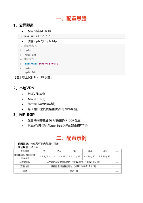
一、配置思路1、公网隧道配置本结点LSR ID1mpls lsr‐id *.*.*.*使能mpls 与 mpls ldp1系统模式下:2 mpls3 mpls ldp4接口模式下:5 interface ethernet 0/0/16 mpls7 mpls ldp【注】以上仅针对P、PE设备。
2、本地VPN创建VPN实例;配置RD、RT;绑定接口与VPN实例;将PE和CE之间的路由实例 与 VPN绑定;3、MP-BGP配置PE间的普通BGP邻居和MP-BGP邻居;将本地VPN路由和mp-bgp之间的路由相互引入二、配置示例组网需求:完成各VPN内部用户互通;地址规划:如下表设备名称P1PE2PE3CE4CE5……loopback / router id/ lsr-id 1.1.1.1 / 32 1.1.1.1 / 32 1.1.1.1 / 32 4.4.4.4 / 32 5.5.5.5 / 32……互联地址段从左到右设备数字组合数(如PE2与P1:10.0.21.0 / 24)……互联地址设备数字对应各自地址(如PE2:10.0.21.2 / 24)……其他详见下图……1、公网隧道配置P与PE的IGP路由(ospf);配置P与PE的LSR ID,并使能系统及接口下的mpls和mpls ldp功能;2、本地VPN创建VPN实例;配置RD、RT;1ip vpn‐instance company‐12 route‐distinguisher 100:13 vpn‐target 100:1 export‐extcommunity4 vpn‐target 100:1 import‐extcommunity56ip vpn‐instance company‐27 route‐distinguisher 100:28 vpn‐target 100:2 export‐extcommunity9 vpn‐target 100:2 import‐extcommunity10 //PE1与PE2该配置相同绑定私网接口与VPN实例;在PE上, 与对应用户(CE设备)相连接口与VPN进行绑定(CE设备无感知,接口只需普通地址配置);1 //以PE2为例,其他接口及PE相同2interface GigabitEthernet0/0/03 ip binding vpn‐instance company‐24 ip address 10.0.82.2 255.255.255.0将PE和CE之间的路由实例 与 VPN绑定;1 //PE22ospf 11 vpn‐instance company‐13 area 0.0.0.04 network 10.0.42.0 0.0.0.2555 //CE46ospf 117 area 0.0.0.08 network 10.0.42.0 0.0.0.2559 network 10.0.64.0 0.0.0.2553、MP-BGP配置PE间的普通BGP邻居(只能传递普通IPv4路由);1bgp 100 //PE2配置2 peer 3.3.3.3 as‐number 1003 peer 3.3.3.3 connect‐interface LoopBack045bgp 100 //PE3配置6 peer 2.2.2.2 as‐number 1007 peer 2.2.2.2 connect‐interface LoopBack0配置PE间的MP-BGP邻居(能传递BGP mpls VPN的私网路由,即VPNv4路由);建立MP-BGP邻居前提是PE间已经建立了普通的BGP邻居;1BGP 100 //PE2配置2 ipv4‐family vpnv43 peer 3.3.3.3 enable45BGP 100 //PE3配置6 ipv4‐family vpnv47 peer 2.2.2.2 enable配置本地VPN路由和mp-bgp之间的路由相互引入;建立MP-BGP邻居前提是PE间已经建立了普通的BGP邻居;1 bgp 100 //BGP中引入直连和IGP2 ipv4‐family vpn‐instance company‐13 import‐route direct4 import‐route ospf 115 ipv4‐family vpn‐instance company‐225 ip address 10.0.21.1 255.255.255.026 mpls27 mpls ldp28#29interface Ethernet0/0/130 ip address 10.0.13.1 255.255.255.031 mpls32 mpls ldp33#34interface Serial0/0/035 link‐protocol ppp36#37interface Serial0/0/138 link‐protocol ppp39#40interface Serial0/0/241 link‐protocol ppp42#43interface Serial0/0/344 link‐protocol ppp45#46interface GigabitEthernet0/0/047#48interface GigabitEthernet0/0/149#50interface GigabitEthernet0/0/251#52interface GigabitEthernet0/0/353#54wlan55#56interface NULL057#58interface LoopBack059 ip address 1.1.1.1 255.255.255.255 60#61ospf 162 area 0.0.0.027 accounting‐scheme default28 domain default29 domain default_admin30 local‐user admin password cipher F<Z4DJzy<+jKUGU‐KkpB7bo#31 local‐user admin service‐type http32#33firewall zone Local34 priority 1635#36interface Ethernet0/0/037 ip binding vpn‐instance company‐138 ip address 10.0.42.2 255.255.255.039#40interface Ethernet0/0/141 ip address 10.0.21.2 255.255.255.042 mpls43 mpls ldp44#45interface Serial0/0/046 link‐protocol ppp47#48interface Serial0/0/149 link‐protocol ppp50#51interface Serial0/0/252 link‐protocol ppp53#54interface Serial0/0/355 link‐protocol ppp56#57interface GigabitEthernet0/0/058 ip binding vpn‐instance company‐259 ip address 10.0.82.2 255.255.255.060#61interface GigabitEthernet0/0/162#63interface GigabitEthernet0/0/264#65interface GigabitEthernet0/0/366#67wlan68#69interface NULL070#71interface LoopBack072 ip address 2.2.2.2 255.255.255.25573#74bgp 10075 peer 3.3.3.3 as‐number 10076 peer 3.3.3.3 connect‐interface LoopBack077 #78 ipv4‐family unicast79 undo synchronization80 peer 3.3.3.3 enable81 #82 ipv4‐family vpnv483 policy vpn‐target84 peer 3.3.3.3 enable85 #86 ipv4‐family vpn‐instance company‐187 import‐route direct88 import‐route ospf 1189 #90 ipv4‐family vpn‐instance company‐291 import‐route direct92 import‐route ospf 1293#94ospf 195 area 0.0.0.096 network 10.0.21.0 0.0.0.25597 network 2.2.2.2 0.0.0.098#99ospf 11 vpn‐instance company‐1100 import‐route bgp101 area 0.0.0.0102 network 10.0.42.0 0.0.0.25525 authentication‐scheme default26 authorization‐scheme default27 accounting‐scheme default28 domain default29 domain default_admin30 local‐user admin password cipher F5S!+T‐YL&:z9:%F`[a=vbt#31 local‐user admin service‐type http32#33firewall zone Local34 priority 1635#36interface Ethernet0/0/037 ip address 10.0.13.3 255.255.255.038 mpls39 mpls ldp40#41interface Ethernet0/0/142 ip binding vpn‐instance company‐143 ip address 10.0.35.3 255.255.255.044#45interface Serial0/0/046 link‐protocol ppp47#48interface Serial0/0/149 link‐protocol ppp50#51interface Serial0/0/252 link‐protocol ppp53#54interface Serial0/0/355 link‐protocol ppp56#57interface GigabitEthernet0/0/058 ip binding vpn‐instance company‐259 ip address 10.0.39.3 255.255.255.060#61interface GigabitEthernet0/0/162#63interface GigabitEthernet0/0/264#65interface GigabitEthernet0/0/366#67wlan68#69interface NULL070#71interface LoopBack072 ip address 3.3.3.3 255.255.255.25573#74bgp 10075 peer 2.2.2.2 as‐number 10076 peer 2.2.2.2 connect‐interface LoopBack077 #78 ipv4‐family unicast79 undo synchronization80 peer 2.2.2.2 enable81 #82 ipv4‐family vpnv483 policy vpn‐target84 peer 2.2.2.2 enable85 #86 ipv4‐family vpn‐instance company‐187 import‐route direct88 import‐route ospf 1389 #90 ipv4‐family vpn‐instance company‐291 import‐route direct92 import‐route ospf 1493#94ospf 195 area 0.0.0.096 network 10.0.13.0 0.0.0.25597 network 3.3.3.3 0.0.0.098#99ospf 13 vpn‐instance company‐15 authentication‐scheme default6 authorization‐scheme default7 accounting‐scheme default8 domain default9 domain default_admin10 local‐user admin password cipher a9uRU{EO!7ECB7Ie7'/)Gbd#11 local‐user admin service‐type http12#13firewall zone Local14 priority 1615#16interface Ethernet0/0/017 ip address 10.0.35.5 255.255.255.018#19interface Ethernet0/0/120 ip address 10.0.57.5 255.255.255.021#22interface Serial0/0/023 link‐protocol ppp24#25interface Serial0/0/126 link‐protocol ppp27#28interface Serial0/0/229 link‐protocol ppp30#31interface Serial0/0/332 link‐protocol ppp33#34interface GigabitEthernet0/0/035#36interface GigabitEthernet0/0/137#38interface GigabitEthernet0/0/239#40interface GigabitEthernet0/0/32sysname Huawei3#4aaa5 authentication‐scheme default6 authorization‐scheme default7 accounting‐scheme default8 domain default9 domain default_admin10 local‐user admin password cipher {07;SSP`4Kpe}@HMNPn@fba#11 local‐user admin service‐type http12#13firewall zone Local14 priority 1615#16interface Ethernet0/0/017 ip address 10.0.39.9 255.255.255.018#19interface Ethernet0/0/120 ip address 10.0.90.9 255.255.255.021#22interface Serial0/0/023 link‐protocol ppp24#25interface Serial0/0/126 link‐protocol ppp27#28interface Serial0/0/229 link‐protocol ppp30#31interface Serial0/0/332 link‐protocol ppp33#34interface GigabitEthernet0/0/035#36interface GigabitEthernet0/0/137#38interface GigabitEthernet0/0/240interface GigabitEthernet0/0/341#42wlan43#44interface NULL045#46ospf 1447 area 0.0.0.048 network 10.0.39.0 0.0.0.25549 network 10.0.90.0 0.0.0.25550#51user‐interface con 052user‐interface vty 0 453user‐interface vty 16 2054#55return~ END ~。
BGP MPLS IP VPN 配置实例
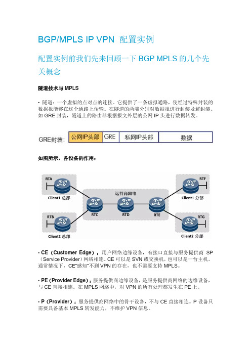
BGP/MPLS IP VPN 配置实例配置实例前我们先来回顾一下BGP MPLS的几个先关概念隧道技术与MPLS• 隧道:一个虚拟的点对点的连接。
它提供了一条虚拟通路,使经过特殊封装的数据报能够在这个通路上传输。
在隧道的两端分别对数据报进行封装及解封装。
如GRE封装,隧道上的路由器根据报文外层的公网IP头进行数据转发。
如图所示,各设备的作用:•CE(Customer Edge):用户网络边缘设备,有接口直接与服务提供商SP (Service Provider)网络相连。
CE可以是SVN或交换机,也可以是一台主机。
通常情况下,CE“感知”不到VPN的存在,也不需要支持MPLS。
•PE(Provider Edge):服务提供商边缘设备,是服务提供商网络的边缘设备,与CE直接相连。
在MPLS网络中,对VPN的所有处理都发生在PE上。
•P(Provider):服务提供商网络中的骨干设备,不与CE直接相连。
P设备只需要具备基本MPLS转发能力,不维护VPN信息。
用户设备所在的区域,称为一个站点(Site),站点是指相互之间具备IP连通性的一组IP系统,并且这组IP系统的IP连通性不需通过运营商网络实现。
传统的VPN技术存在一些固有的缺陷,导致客户组网时的很多需求无法得到满足,并且实施比较复杂,MPLS VPN的出现解决了传统VPN技术的固有缺陷——地址空间的重叠问题。
• MPLS是天然的隧道,隧道上的路由器可以根据报文的MPLS头进行报文转发。
VRF(Virtual Routing and Forwarding):虚拟路由及转发,它是一种VPN 路由和转发实例。
• 一台PE 路由器,由于可能同时连接了多个VPN 用户,这些用户(的路由)彼此之间需要相互隔离,那么这时候就用到了VRF,PE 路由器上每一个VPN 都有一个VRF。
PE 路由器除了维护全局IP 路由表之外,还为每个VRF 维护一张独立的IP 路由表,这张路由表称为VRF 路由表。
BGP-MPLS-VPN配置与故障排查

PE1:
interface Ethernet0/1 ip binding vpn-instance vpn1 ip address 192.168.1.1 255.255.255.252
# interface Ethernet0/2 ip binding vpn-instance vpn2 ip address 172.32.1.1 255.255.255.252
网络环境和需求
VPN1 CE1
用户1: 192.168.254.1/24
用户2: 172.32.254.1/24
VPN1 CE3
Loopback0:1.1.1.1/32
Loopback0:1.1.1.2/32
PE1
E0/1 E0/0
Loopback0:1.1.1.3/32 PE2
.2
E1/0
.6
E0/1
配置接口与VPN实例绑定 interface interface-type interface-number ip binding vpn-instance vpn-instance-name
配置PE与CE之间的路由实例与VPN绑定,以OSPF为例: ospf [ process-id | router-id router-id | vpn-instance vpn-instance-name ]
BGP MPLS VPN的配置思路与对BGP MPLS VPN技 术原理的理解一致,分为以下三个步骤:
配置公网隧道 配置本地VPN 配置MP-BGP
5
目录
BGP MPLS VPN配置思路 BGP MPLS VPN配置命令 BGP MPLS VPN配置示例 BGP MPLS VPN故障排查
华为BGP MPLS VPN实验及配置思路和排错
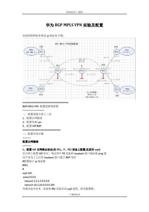
华为BGP MPLS VPN实验及配置实验的组网拓扑图及ip地址如下图:===================================BGP MPLS VPN 配置思路和排错---------------------------一、配置思路大体上三步1、配置公网隧道2、配置本地vpn3、配置MP-BGP=============================二、配置具体步骤----------配置公网隧道-----------1、配置IGP公网路由协议(在PE1、P、PE2设备上配置,这里用ospf)在公网上配置IGP协议、保证两个PE设备的loopback接口地址能ping通这个是为了之后用loopback接口建立BGP邻居#配置接口ip地址略#PE1#ospf 145area 0.0.0.0network 2.2.2.2 0.0.0.0network 10.1.24.0 0.0.0.255用相同命令在P、设备和PE2设备启动ospf进程、相关配置略。
我们可以通过display ip routing-table查看有无学习到对端PE设备的loopback接口ip如果无法ping通对端PE设备的loopback地址,就结合OSPF排错思路进行相关排错2、使能mpls和mpls ldp(需要在公网的PE和P设备上使能,全局和接口模式都要使能)#PE1#mpls lsr-id 2.2.2.2#mpls#mpls ldp#interface GigabitEthernet0/1/2port link-mode routeip address 10.1.24.2 255.255.255.0mplsmpls ldp注意:#在使能mpls 和mpls ldp 功能的时候是既要在全局模式下又要在接口模式下#PE和P设备中的mpls lsr-id 2.2.2.2这后面的这个地址,在ip路由中要相互可达,否则无法正常建立ldp邻居关系#一般我们将mpls lsr-id 后面的这个地址用设备的loopback地址即可,只要保证loopback地址能相互ping通即可排错:我们可以通过display mpls ldp session查看公网设备间的mpls ldp邻居是否正常建立,operational为正常状态进一步通过display mpls ldp lsp查看有无建立隧道、lsp是单向的所以要再公网每台设备上查看----------配置本地vpn实例----------3、按照需求配置vpn实例(只需要在两个PE设备上配置)#PE1#ip vpn-instance vpn1route-distinguisher 100:1vpn-target 100:1 export-extcommunityvpn-target 100:1 import-extcommunity#ip vpn-instance vpn2route-distinguisher 100:2vpn-target 100:2 export-extcommunityvpn-target 100:2 import-extcommunity4、将私网接口与vpn实例绑定#PE1interface GigabitEthernet0/1/0port link-mode routeip binding vpn-instance vpn1ip address 10.1.12.2 255.255.255.0#interface GigabitEthernet0/1/1port link-mode routeip binding vpn-instance vpn2ip address 10.1.23.2 255.255.255.0注意:如果接口之前已经配置好了ip,在绑定vpn实例之后ip地址会丢失,需要重新配置即可,建议绑定之后再配置私网ip5、配置PE设备与CE设备之间的路由协议(这里也用0spf)这里面PE设备相对特殊,PE运行的路由协议需要和vpn实例进行绑定,以就是运行路由协议的多实例。
MPLS VPN的实验报告

南京邮电大学通达学院实验报告题目: MPLS VPN的实现专业:通信工程学生姓名:***班级学号: ********指导教师:***指导单位:日期:2018 年 5 月 7 日至 2018 年 5 月 7 日实验名称: MPLS VPN的实现一、实验目的该实验通过MPLS VPN的数据配置,使学生掌握路由器相关接口的IP地址设置、路由协议的配置以及MPLS VPN的完整的创建过程, 从而加深对IP网络的IP编址、路由协议以及MPLS的相关理论的理解。
二、实验内容利用网络模拟器GNS3模拟Cisco的实验环境,搭建IP网络,完成CE、PE和P路由器上的数据配置, 使属于同一VPN的两个路由器能够互通。
三、实验设备1.硬件:PC机。
2.软件:①网络模拟器 GNS3-2.0.3-all-in-one②终端仿真程序 SecureCRT③ Cisco IOS文件 C3640-JK9O3S-M-12.4(7a).BIN④抓包软件Wireshark四、安装软件1. 安装SecureCRT软件2. 安装Wireshark软件3. 安装GNS3软件,完成配置(此部分可贴图说明安装过程)五、实验步骤1. 按图5.1创建网络拓扑结构。
图5.1 网络拓扑结构2.配置各个路由器相关接口的IP地址。
f0/0接口f1/0接口Lookback R1 1.10.12.1/24 1.1.1.1/32 R2 1.10.12.2/24 1.10.23.2/24 2.2.2.2/32 R3 1.10.23.3/24 1.10.34.3/24 3.3.3.3/32 R4 1.10.34.4/24 1.10.45.4/24 4.4.4.4/32 R5 1.10.45.5/24 1.10.56.5/24 5.5.5.5/32 R6 1.10.56.6/24 6.6.6.6/32R1(CE1) R2(PE1) R3(P1)int f0/0ip address 1.10.12.1 255.255.255.0 no shutdownint lo0ip address 1.1.1.1 255.255.255.255int f0/0ip address 1.10.12.2 255.255.255.0no shutdownint f1/0ip address 1.10.23.2 255.255.255.0no shutdownint lo0ip address 2.2.2.2 255.255.255.255int f0/0ip address 1.10.23.3 255.255.255.0no shutdownint f1/0ip address 1.10.34.3 255.255.255.0no shutdownint lo0ip address 3.3.3.3 255.255.255.255R4(P2) R5(PE2) R6(CE2)int f0/0ip address 1.10.34.4 255.255.255.0 no shutdownint f1/0ip address 1.10.45.4 255.255.255.0 no shutdownint lo0ip address 4.4.4.4 255.255.255.255int f0/0ip address 1.10.45.5 255.255.255.0no shutdownint f1/0ip address 1.10.56.5 255.255.255.0no shutdownint lo0ip address 5.5.5.5 255.255.255.255int f0/0ip address 1.10.56.6 255.255.255.0no shutdownint lo0ip address 6.6.6.6 255.255.255.255点击图标启动各路由器,在R2和R3之间的链路上启动Wireshark软件抓包。
BGP MPLS VPN实验操作部分

华为3COM合资公司
5
配置
•MPLS配置
•MP-BGP配置
•配置vpn-intstance •配置RD •配置RT •配置PE到CE之间的连接 •将vpn-intstance与接口关连 •PE与CE之间的路由协议 •配置 MP-BGP
•调试命令
•Trouble shooting
华为3COM合资公司 网络创造无限
华为3COM合资公司
网络创造无限
3
查看MPLS的邻居状态
[NE16E_01]dis mpls ldp session Showing information about all sessions: Peer LDP ID: 10.0.0.41:0; Local LDP ID: 10.0.0.1:1 Tcp connection:10.0.0.41 - 10.0.1.198 Session State: Operational Session Role: Active Session existed time: 11 days 5 hours 47 minutes 32 seconds KeepAlive packet sent/received: 40467/38849 Negotiated Value of Keepalive Timer: 60 Peer PV Limit: 0 LDP discovery Interface:Pos3/1/0
此命令只可以查看学习到的BGP路由的私网标签情况,对于本地始发的路由无 法查看,必须通过命令 display bgp vpnv4 all routing-table查看。
华为3COM合资公司
网络创造无限
16
Ping&Telnet&tracert
mpls vpn bgp

BGP MPLS VPN 分享刚做网络3年网络界的嫩手。
维护的网络就是MPLS VPN 内部为一个区域的自治系统100 。
下面我模拟的一个实验全省的缩写。
呈上来往对大家有帮助。
当然也可以提意见了!!!一定要提的啊!实验环境:5台路由器7200系列支持MPLS实验拓扑: (VPNA) CE -----PE------P -----PE ------CE (VPNB)实验目的: VPNA 100.1.1.1 lookback 能PING 通VPNB 200.1.1.1 的lookback这篇文档难度较小而且配置绝对是最完整的。
r1#sh runBuilding configuration...Current configuration : 1028 bytes!version 12.3service timestamps debug datetime msecservice timestamps log datetime msecno service password-encryption!hostname r1!boot-start-markerboot-end-marker!!no aaa new-modelip subnet-zero!!!ip cefip audit po max-events 100!!!!!!!!!!!!!!!!!!interface Loopback0ip address 100.1.1.1 255.255.255.0!interface FastEthernet0/0no ip addressshutdownduplex half!interface Serial1/0ip address 10.1.1.1 255.255.255.0 serial restart-delay 0!interface Serial1/1no ip addressshutdownserial restart-delay 0!interface Serial1/2no ip addressshutdownserial restart-delay 0!interface Serial1/3no ip addressshutdownserial restart-delay 0!router bgp 200no synchronizationbgp log-neighbor-changesnetwork 100.1.1.0 mask 255.255.255.0 neighbor 10.1.1.2 remote-as 100no auto-summary!ip classlessno ip http serverno ip http secure-server!!!!!!!!!gatekeepershutdown!!line con 0stopbits 1line aux 0stopbits 1line vty 0 4login!!endr2#sh runBuilding configuration...Current configuration : 1661 bytes!version 12.3service timestamps debug datetime msec service timestamps log datetime msec no service password-encryption!hostname r2!boot-start-markerboot-end-marker!!no aaa new-modelip subnet-zero!!!ip vrf vpnard 100:1route-target export 100:1route-target import 100:1 maximum routes 10 warning-only!ip cefip audit po max-events 100!!!!!!!!!!!!!!!!!!interface Loopback0ip address 10.10.1.1 255.255.255.255 !interface FastEthernet0/0no ip addressshutdownduplex half!interface Serial1/0ip vrf forwarding vpnaip address 10.1.1.2 255.255.255.0 serial restart-delay 0!interface Serial1/1ip address 10.10.12.1 255.255.255.0 ip ospf network point-to-pointtag-switching ipserial restart-delay 0!interface Serial1/2no ip addressshutdownserial restart-delay 0!interface Serial1/3no ip addressshutdownserial restart-delay 0!router ospf 1router-id 10.10.1.1log-adjacency-changesnetwork 10.10.1.0 0.0.0.255 area 0network 10.10.12.0 0.0.0.255 area 0!router bgp 100no synchronizationbgp log-neighbor-changesneighbor 10.10.3.3 remote-as 100neighbor 10.10.3.3 update-source Loopback0 no auto-summary!address-family vpnv4neighbor 10.10.3.3 activateneighbor 10.10.3.3 send-community extended exit-address-family!address-family ipv4 vrf vpnaredistribute connectedneighbor 10.1.1.1 remote-as 200neighbor 10.1.1.1 activateno auto-summaryno synchronizationexit-address-family!ip classlessno ip http serverno ip http secure-server!!!!!!!!gatekeepershutdown!!line con 0stopbits 1line aux 0stopbits 1line vty 0 4login!!endr2#r3#sh runBuilding configuration...Current configuration : 1082 bytes!version 12.3service timestamps debug datetime msec service timestamps log datetime msec no service password-encryption!hostname r3!boot-start-markerboot-end-marker!!no aaa new-modelip subnet-zero!!!ip cefip audit po max-events 100!!!!!!!!!!!!!!!!!interface FastEthernet0/0no ip addressshutdownduplex half!interface Serial1/0ip address 10.10.23.2 255.255.255.0 ip ospf network point-to-pointtag-switching ipserial restart-delay 0clock rate 64000!interface Serial1/1ip address 10.10.12.2 255.255.255.0 ip ospf network point-to-pointtag-switching ipserial restart-delay 0clock rate 64000!interface Serial1/2no ip addressshutdownserial restart-delay 0!interface Serial1/3no ip addressshutdownserial restart-delay 0!router ospf 1log-adjacency-changesnetwork 10.10.12.0 0.0.0.255 area 0network 10.10.23.0 0.0.0.255 area 0!ip classlessno ip http serverno ip http secure-server!!!!!!!!!gatekeepershutdown!!line con 0stopbits 1line aux 0--More--*Aug 7 22:51:07.039: %LDP-5-NBRCHG: TDP Neighbor 10.10.12.1:0 is DOWN (Discovery Hello Hold Time stopbits 1line vty 0 4login!!Endr4#sh runBuilding configuration...Current configuration : 1632 bytes!version 12.3service timestamps debug datetime msecservice timestamps log datetime msecno service password-encryptionhostname r4!boot-start-markerboot-end-marker!!no aaa new-modelip subnet-zero!!!ip vrf vpnbrd 100:1route-target export 100:1route-target import 100:1!ip cefip audit po max-events 100!!!!!!!!!!!!!!!!!!interface Loopback0ip address 10.10.3.3 255.255.255.255 !interface FastEthernet0/0no ip addressshutdownduplex halfinterface Serial1/0ip address 10.10.23.3 255.255.255.0ip ospf network point-to-pointtag-switching ipserial restart-delay 0!interface Serial1/1ip vrf forwarding vpnbip address 10.10.10.1 255.255.255.0serial restart-delay 0clock rate 64000!interface Serial1/2no ip addressshutdownserial restart-delay 0!interface Serial1/3no ip addressshutdownserial restart-delay 0!router ospf 1log-adjacency-changesnetwork 10.10.3.0 0.0.0.255 area 0network 10.10.23.0 0.0.0.255 area 0!router bgp 100no synchronizationbgp log-neighbor-changesneighbor 10.10.1.1 remote-as 100neighbor 10.10.1.1 update-source Loopback0 no auto-summary!address-family vpnv4neighbor 10.10.1.1 activateneighbor 10.10.1.1 send-community extended exit-address-family!address-family ipv4 vrf vpnbredistribute connectedneighbor 10.10.10.2 remote-as 300 neighbor 10.10.10.2 activateno auto-summaryno synchronizationexit-address-family!ip classlessno ip http serverno ip http secure-server!!!!!!!!!gatekeepershutdown!!line con 0stopbits 1line aux 0stopbits 1line vty 0 4login!!Endr5#r5#sh runBuilding configuration...Current configuration : 1047 bytes!version 12.3service timestamps debug datetime msec service timestamps log datetime msec no service password-encryption!hostname r5!boot-start-markerboot-end-marker!!no aaa new-modelip subnet-zero!!!ip cefip audit po max-events 100!!!!!!!!!!!!!!!!!!interface Loopback0ip address 200.1.1.1 255.255.255.0 !interface FastEthernet0/0no ip addressshutdownduplex half!interface Serial1/0no ip addressshutdownserial restart-delay 0!interface Serial1/1ip address 10.10.10.2 255.255.255.0 serial restart-delay 0interface Serial1/2no ip addressshutdownserial restart-delay 0!interface Serial1/3no ip addressshutdownserial restart-delay 0!router bgp 300no synchronizationbgp log-neighbor-changes network 200.1.1.0 mask 255.0.0.0 network 200.1.1.0neighbor 10.10.10.1 remote-as 100 no auto-summary!ip classlessno ip http serverno ip http secure-server!!!!!!!!!gatekeepershutdown!!line con 0stopbits 1line aux 0stopbits 1line vty 0 4login!!endr5#。
- 1、下载文档前请自行甄别文档内容的完整性,平台不提供额外的编辑、内容补充、找答案等附加服务。
- 2、"仅部分预览"的文档,不可在线预览部分如存在完整性等问题,可反馈申请退款(可完整预览的文档不适用该条件!)。
- 3、如文档侵犯您的权益,请联系客服反馈,我们会尽快为您处理(人工客服工作时间:9:00-18:30)。
eNSP实验:BGP-MPLS-VPNBGP MPLS VPN 配置实验目录1网络拓扑 (5)2配置文件 (5)2.1PE1的相关配置52.1.1在MPLS骨干网上配置IGP协议,实现骨干网PE和P的互通 (5)2.1.2在PE1上配置与PE2、P的IBGP62.1.3MPLS骨干网上配置MPLS基本能力和MPLS LDP,建立LDP LSP (7)2.1.4在PE设备上配置VPN实例,将CE接入PE (7)2.1.5在PE与CE之间建立EBGP对等体,引入VPN路由 (9)2.2P的相关配置102.2.1在MPLS骨干网上配置IGP协议,实现骨干网PE和P的互通 (10)2.2.2P上配置与PE1、PE2的IBGP112.2.3MPLS骨干网上配置MPLS基本能力和MPLS LDP,建立LDP LSP (12)2.2.4 (xxx)错误!未定义书签。
2.3PE2相关配置 142.3.1在MPLS骨干网上配置IGP协议,实现骨干网PE和P的互通 (14)2.3.2在PE2上配置与P、PE1的IBGP152.3.3MPLS骨干网上配置MPLS基本能力和MPLS LDP,建立LDP LSP (15)2.3.4在PE设备上配置VPN实例,将CE接入PE (16)2.3.5PE与CE之间建立EBGP对等体,引入VPN路由 (17)2.4CE1的相关配置 182.5CE2的相关配置 192.6CE3的相关配置192.7CE4的相关配置203实验结果: (20)3.1PE1 vpn 路由表203.2P路由表213.3Ping:相同VPN之间可以通,不同VPN之间不通, (23)1网络拓扑2配置文件2.1PE1的相关配置2.1.1在MPLS骨干网上配置IGP-OSPF协议,实现骨干网PE和P的互通#Sysna PE1ospf 1area 0.0.0.0network 10.0.0.0 0.0.0.3network 1.1.1.1 0.0.0.0 (igp-ospf)#interface LoopBack0ip address 1.1.1.1 255.255.255.255ospf enable 1 area 0.0.0.0 端口使能ospf)network 10.0.0.0 255.255.255.252peer 2.2.2.2 enable Array peer 3.3.3.3 enable (宣告网络)#2.1.3MPLS骨干网上配置MPLS基本能力和MPLS LDP,建立LDP LSP#mpls lsr-id 1.1.1.1 mplslsp-trigger allmpls ldp(使能mpls)#interface Ethernet0/0/0mplsmpls ldp(端口使能mpls)#2.1.4在PE设备上配置VPN实例,将CE接入PEip vpn-instance VPN1创建并进入VPN实例视图ipv4-familyroute-distinguisher 100:1 为vpn-instance创建RDvpn-target 111:1 export-extcommunity 为vpn-instance创建vpn-target扩展团体vpn-target 111:1 import-extcommunity (配置VPN1)#ip vpn-instance VPN2ipv4-familyroute-distinguisher 200:1vpn-target 222:1 export-extcommunityvpn-target 222:1 import-extcommunity (配置VPN2)#interface Ethernet0/0/1ip binding vpn-instance VPN1 将接口与vpn-instance关联ip address 10.0.0.13 255.255.255.252 (端口绑定VPN)interface GigabitEthernet0/0/0ip binding vpn-instance VPN2ip address 10.0.0.9 255.255.255.252 (端口绑定VPN)#2.1.5在PE与CE之间建立EBGP对等体,引入VPN路由#bgp 65115ipv4-family vpnv4进入MBGP的VPNv4地址族视图policy vpn-targetpeer 2.2.2.2 enable激活MBGP对等体peer 3.3.3.3 enable(建立邻居关系)#ipv4-family vpn-instance VPN1进入BGP的VPN地址族视图import-route directimport-route static (配置 vpn路由)ipv4-family vpn-instance VPN2import-route directimport-route static (配置 vpn路由)#ip route-static vpn-instance VPN1 0.0.0.00.0.0.0 10.0.0.14ip route-static vpn-instance VPN2 0.0.0.00.0.0.0 10.0.0.10 (配置vpn静态路由:PE和CE间通过静态路由链接的配置)#2.2P的相关配置2.2.1在MPLS骨干网上配置IGP协议,实现骨干网PE和P的互通#sysna Pospf 1area 0.0.0.0network 10.0.0.0 0.0.0.3network 10.0.0.4 0.0.0.3network 2.2.2.2 0.0.0.0 (igp-ospf)#interface LoopBack0ip address 2.2.2.2 255.255.255.255ospf enable 1 area 0.0.0.0 (端口使能ospf)interface Ethernet0/0/0ip address 10.0.0.2 255.255.255.252ospf enable 1 area 0.0.0.0 (端口使能ospf)interface Ethernet0/0/1ip address 10.0.0.5 255.255.255.252ospf enable 1 area 0.0.0.0 (端口使能ospf)#2.2.2P上配置与PE1、PE2的IBGP#bgp 65115router-id 2.2.2.2peer 1.1.1.1 as-number 65115peer 1.1.1.1 connect-interfaceEthernet0/0/0peer 3.3.3.3 as-number 65115peer 3.3.3.3 connect-interfaceEthernet0/0/1 (配置bgp)#ipv4-family unicastundo synchronizationnetwork 2.2.2.2 255.255.255.255network 10.0.0.0 255.255.255.252network 10.0.0.4 255.255.255.252peer 1.1.1.1 enablepeer 3.3.3.3 enable (宣告网络)#2.2.3MPLS骨干网上配置MPLS基本能力和MPLS LDP,建立LDP LSP#mpls lsr-id 2.2.2.2mplslsp-trigger allmpls ldp(使能mpls)#interface Ethernet0/0/0mplsmpls ldp (端口使能mpls)#interface Ethernet0/0/1mplsmpls ldp (端口使能mpls)#2.2.4建立P与PE1、PE2的邻居关系#bgp 65115ipv4-family vpnv4policy vpn-targetpeer 1.1.1.1 enablepeer 3.3.3.3 enable (建立邻居关系)#2.3PE2相关配置和PE1类似2.3.1在MPLS骨干网上配置IGP协议,实现骨干网PE和P的互通#Sysna PE2ospf 1area 0.0.0.0network 10.0.0.4 0.0.0.3network 3.3.3.3 0.0.0.0 (igp-ospf)#interface LoopBack0ip address 3.3.3.3 255.255.255.255ospf enable 1 area 0.0.0.0 端口使能ospf)interface Ethernet0/0/0ip address 10.0.0.6 255.255.255.252ospf enable 1 area 0.0.0.0 (端口使能ospf)#2.3.2在PE2上配置与P、PE1的IBGP#bgp 65115router-id 3.3.3.3peer 1.1.1.1 as-number 65115peer 1.1.1.1 connect-interface LoopBack0(配置bgp)ipv4-family unicastundo synchronizationnetwork 3.3.3.3 255.255.255.255network 10.0.0.4 255.255.255.252peer 2.2.2.2 enablepeer 1.1.1.1 enable (宣告网络)#2.3.3MPLS骨干网上配置MPLS基本能力和MPLS LDP,建立LDP LSP#mpls lsr-id 3.3.3.3mplslsp-trigger allmpls ldp(使能mpls)#interface Ethernet0/0/0mplsmpls ldp(端口使能mpls)#2.3.4在PE设备上配置VPN实例,将CE接入PE#ip vpn-instance VPN1ipv4-familyroute-distinguisher 100:1vpn-target 111:1 export-extcommunityvpn-target 111:1 import-extcommunity# (配置VPN1)ip vpn-instance VPN2ipv4-familyroute-distinguisher 200:1vpn-target 222:1 export-extcommunityvpn-target 222:1 import-extcommunity(配置VPN2)#interface Ethernet0/0/1ip binding vpn-instance VPN1ip address 10.0.0.17 255.255.255.252 (端口绑定VPN)interface GigabitEthernet0/0/0ip binding vpn-instance VPN2ip address 10.0.0.21 255.255.255.252 (端口绑定VPN)#2.3.5PE与CE之间建立EBGP对等体,引入VPN路由bgp 65115ipv4-family vpnv4policy vpn-targetpeer 2.2.2.2 enablepeer 1.1.1.1 enable(建立邻居关系)#ipv4-family vpn-instance VPN1import-route directimport-route static (配置 vpn路由)ipv4-family vpn-instance VPN2import-route directimport-route static (配置 vpn路由)#ip route-static vpn-instance VPN1 0.0.0.0 0.0.0.0 10.0.0.18ip route-static vpn-instance VPN2 0.0.0.0 0.0.0.0 10.0.0.22#(配置vpn静态路由)2.4CE1的相关配置#Sysn CE1interface Ethernet0/0/0ip address 10.0.0.10 255.255.255.252ip route-static 0.0.0.0 0.0.0.0 10.0.0.9(配置静态路由)#save2.5CE2的相关配置#Sysn CE2interface Ethernet0/0/0ip address 10.0.0.14 255.255.255.252 ip route-static 0.0.0.0 0.0.0.0 10.0.0.13 #2.6CE3的相关配置#Sysn CE3interface Ethernet 0/0/0ip address 10.0.0.18 255.255.255.252 ip route-static 0.0.0.0 0.0.0.0 10.0.0.17 #2.7CE4的相关配置#SysSysn CE4interface Ethernet 0/0/0ip address 10.0.0.22 255.255.255.252 ip route-static 0.0.0.0 0.0.0.0 10.0.0.21 #3实验结果:3.1PE1 vpn 路由表[PE1]disp ip rout[PE1]disp ip routing-tableRoute Flags: R - relay, D - download to fib------------------------------------------------------------------------------Routing Tables: PublicDestinations : 8 Routes : 8Destination/Mask Proto Pre Cost Flags NextHop Interface1.1.1.1/32 Direct 0 0 D 127.0.0.1 LoopBack02.2.2.2/32 OSPF 10 1 D 10.0.0.2 Ethernet0/0/03.3.3.3/32 OSPF 10 2 D 10.0.0.2 Ethernet0/0/010.0.0.0/30 Direct 0 0 D 10.0.0.1 Ethernet0/0/010.0.0.1/32 Direct 0 0 D 127.0.0.1 Ethernet0/0/010.0.0.4/30 OSPF 10 2 D 10.0.0.2 Ethernet0/0/0127.0.0.0/8 Direct 0 0 D 127.0.0.1 InLoopBack0127.0.0.1/32 Direct 0 0 D 127.0.0.1 InLoopBack0[PE1]disp ip routing-table vp[PE1]disp ip routing-table vpn-instance ?STRING<1-31> VPN instance name[PE1]disp ip routing-table vpn-instance VPN1Route Flags: R - relay, D - download to fib------------------------------------------------------------------------------Routing Tables: VPN1Destinations : 4 Routes : 4Destination/Mask Proto Pre Cost Flags NextHop Interface0.0.0.0/0 Static 60 0 RD 10.0.0.14 Ethernet0/0/110.0.0.12/30 Direct 0 0 D 10.0.0.13 Ethernet0/0/110.0.0.13/32 Direct 0 0 D 127.0.0.1 Ethernet0/0/110.0.0.16/30 IBGP 255 0 RD 3.3.3.3 Ethernet0/0/0[PE1][PE1]disp ip routing-table vpn-instance VPN2Route Flags: R - relay, D - download to fib------------------------------------------------------------------------------Routing Tables: VPN2Destinations : 4 Routes : 4Destination/Mask Proto Pre Cost Flags NextHop Interface0.0.0.0/0 Static 60 0 RD 10.0.0.10GigabitEthernet0/0/010.0.0.8/30 Direct 0 0 D 10.0.0.9GigabitEthernet0/0/010.0.0.9/32 Direct 0 0 D 127.0.0.1GigabitEthernet0/0/010.0.0.20/30 IBGP 255 0 RD 3.3.3.3 Ethernet0/0/0 [PE1]3.2P路由表<P>disp ip routingRoute Flags: R - relay, D - download to fib------------------------------------------------------------------------------ Routing Tables: PublicDestinations : 9 Routes : 9Destination/Mask Proto Pre Cost Flags NextHop Interface1.1.1.1/32 OSPF 10 1 D 10.0.0.1 Ethernet0/0/02.2.2.2/32 Direct 0 0 D 127.0.0.1 LoopBack03.3.3.3/32 OSPF 10 1 D 10.0.0.6 Ethernet0/0/110.0.0.0/30 Direct 0 0 D 10.0.0.2 Ethernet0/0/010.0.0.2/32 Direct 0 0 D 127.0.0.1 Ethernet0/0/010.0.0.4/30 Direct 0 0 D 10.0.0.5 Ethernet0/0/110.0.0.5/32 Direct 0 0 D 127.0.0.1 Ethernet0/0/1127.0.0.0/8 Direct 0 0 D 127.0.0.1 InLoopBack0127.0.0.1/32 Direct 0 0 D 127.0.0.1 InLoopBack0PE2 Vpn 路由表<PE2>dis ip routRoute Flags: R - relay, D - download to fib------------------------------------------------------------------------------ Routing Tables: PublicDestinations : 8 Routes : 8Destination/Mask Proto Pre Cost Flags NextHop Interface1.1.1.1/32 OSPF 10 2 D 10.0.0.5 Ethernet0/0/02.2.2.2/32 OSPF 10 1 D 10.0.0.5 Ethernet0/0/03.3.3.3/32 Direct 0 0 D 127.0.0.1 LoopBack010.0.0.0/30 OSPF 10 2 D 10.0.0.5 Ethernet0/0/010.0.0.4/30 Direct 0 0 D 10.0.0.6 Ethernet0/0/010.0.0.6/32 Direct 0 0 D 127.0.0.1 Ethernet0/0/0127.0.0.0/8 Direct 0 0 D 127.0.0.1 InLoopBack0127.0.0.1/32 Direct 0 0 D 127.0.0.1 InLoopBack0<PE2>dis ip rou<PE2>dis ip routing-table vpn-instance VPN1Route Flags: R - relay, D - download to fib------------------------------------------------------------------------------ Routing Tables: VPN1Destinations : 3 Routes : 3Destination/Mask Proto Pre Cost Flags NextHop Interface10.0.0.12/30 IBGP 255 0 RD 1.1.1.1 Ethernet0/0/010.0.0.16/30 Direct 0 0 D 10.0.0.17 Ethernet0/0/110.0.0.17/32 Direct 0 0 D 127.0.0.1 Ethernet0/0/1<PE2>dis ip routing-table vpn-instance VPN2Route Flags: R - relay, D - download to fib------------------------------------------------------------------------------ Routing Tables: VPN2Destinations : 4 Routes : 4Destination/Mask Proto Pre Cost Flags NextHop Interface0.0.0.0/0 Static 60 0 RD 10.0.0.22 GigabitEthernet0/0/0 10.0.0.8/30 IBGP 255 0 RD 1.1.1.1 Ethernet0/0/010.0.0.20/30 Direct 0 0 D 10.0.0.21 GigabitEthernet0/0/0 10.0.0.21/32 Direct 0 0 D 127.0.0.1 GigabitEthernet0/0/0<PE2><P>3.3Ping:相同VPN之间可以通,不同VPN之间不通,CE2-CE4不通<CE2>ping 10.0.0.22PING 10.0.0.22: 56 data bytes, press CTRL_C to breakRequest time outRequest time outRequest time outRequest time outRequest time out--- 10.0.0.22 ping statistics ---5 packet(s) transmitted0 packet(s) received100.00% packet lossCE2-CE3能通<CE2>ping 10.0.0.18PING 10.0.0.18: 56 data bytes, press CTRL_C to breakReply from 10.0.0.18: bytes=56 Sequence=1 ttl=253 time=390 ms Reply from 10.0.0.18: bytes=56 Sequence=2 ttl=253 time=140 ms Reply from 10.0.0.18: bytes=56 Sequence=3 ttl=253 time=140 ms Reply from 10.0.0.18: bytes=56 Sequence=4 ttl=253 time=140 ms Reply from 10.0.0.18: bytes=56 Sequence=5 ttl=253 time=120 ms--- 10.0.0.18 ping statistics ---5 packet(s) transmitted5 packet(s) received0.00% packet lossround-trip min/avg/max = 120/186/390 ms <CE2>。
