VLAN与TRUNK配置
交换机vlan基本配置

交换机上配置静态VLAN1、创建VLAN(1)在全局模式下创建VLAN:switch>enable 进入特权模式switch#configure terminal 进入全局模式switch(config)#vlan vlan-ID创建VLAN号switch(config)#name vlan-name配置VLAN名称switch(config)#mtu mtu-size改变MTU大小(可选命令)switch(config)#end 退出switch(config)#show vlan {name vlan-name|ID vlan-id}验证查看vlanswitch(config)#copy running-config startup-config 保存配置(2)在VLAN数据库中创建VLAN(VLAN数据库模式目前已经过时IOS版本不在支持,推荐使用全局模式配置定义VLAN)switch#vlan datebase 进入VLAN配置状态switch(vlan)#vlan vlan-id name vlan-name创建VLAN号及VLAN名称switch(vlan)#vlan vlan-id mtu mtu-size 修改MTU大小switch(vlan)#exit 更新VLAN数据并退出switch(config)#show vlan {name vlan-name|ID vlan-id}验证查看vlanswitch(config)#copy running-config startup config 保存配置(3)在VLAN中添加、删除端口switch#configure terminal 进入配置状态switch(config)# interface interface-id 进入要分配的端口switch(config)#switchport mode access 定义二层端口switch(config)#switchport access vlan vlan-id把端口划分给某个VLANswitch(config)#end 退出switch#show running-config interface interface-ID验证端口号的VLAN号switch#show interfaces interface-id switchport 验证端口的管理模式和VLAN情况switch#copy running-config startup-config 保存配置使用default interface interface-id命令可以还原接口的默认配置状态(4)验证VLAN的配置switch#show vlan brief 查看VLAN信息的命令switch#show vlan vlan-id查看指定的某一个VLAN信息(5)删除VLAN用no vlan vlan-id命令Switch#configure terminalSwitch(config)#no vlan vlan-id++++++++++++++++++++++++++++++++++++++++++++++++++++++++++++++++++++ 2、Turnk的模式和协商接口的配置模式1、switchport mode access将接口设定为永久的非中继模式,并协商将链路转换为非中继链路,即使邻接端口是中继端口,此接口也会成为非中继接口2、switchport mode dynamic desirable 使得接口主动尝试将链路转换为中继链路。
【数通大讲坛 10】vlan、trunk的概念和配置
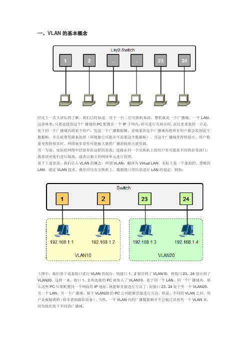
一、VLAN的基本概念经过上一次大讲坛的了解,我们已经知道,对于一台二层交换机来说,整机就是一个广播域、一个LAN。
这意味着,只要连接到这个广播域的PC配置在一个IP子网内,即可进行互相访问,而且更重要的一点是,处于同一个广播域内的某个用户,发送一个广播数据帧,意味着在这个广播域内的所有用户都会收到这个数据帧,并且耗费资源来处理(即使她它可能并不需要这个数据帧)。
当这个广播域变得特别大、用户数量变得特别多时,网络就非常有可能被大量的广播消耗掉大量资源。
另一方面,实际的网络中经常存在这样的需求:连接在同一个交换机上的用户有可能是不同的业务部门,我希望对他们进行隔离,或者以独立的网络单元进行管理。
基于上述需求,我们引入VLAN的概念,所谓VLAN,翻译为Virtual LAN,实际上是一个虚拟的、逻辑的LAN,通过VLAN技术,我们可以在交换机上,根据接口等信息进行LAN的划定。
例如:上图中,我们基于设备接口进行VLAN的划分。
将接口1、2划分到了VLAN10,将接口23、24划分到了VLAN20。
这样一来,接口1、2所连接的PC就加入了VLAN10,处于同一个LAN、同一个广播域内,那么这些PC只要配置同一个网段的IP地址,就能够直接进行互访了。
而接口23、24处于另一个VLAN20,另一个LAN、另一个广播域。
属于VLAN20的PC之间能够直接进行互访。
但是,不同的VLAN之间,用户是被隔离的(除非借助路由设备),当然,一个VLAN内的广播数据帧并不会被泛洪到另一个VLAN来,因为他们处于不同的广播域。
有了VLAN技术,我们的网络设计将更加灵活、更加可控。
VLAN是一个虚拟的LAN,不再受设备的限制。
我们可以根据实际的业务环境需要,灵活的进行VLAN的规划。
而VLAN更可以跨交换机,因此VLAN的成员,也就是业务PC所处的位置就非常灵活了。
例如上图所示,你可能希望每个部门单独划分到一个LAN 中,部分之间互相隔离,而一个部门的员工又往往未必在同一楼层,可能分散在不同的楼层,那么有了VLAN 技术,完全可以把分散在不同楼层的业务PC划分入一个VLAN。
计算机网络基础-TRUNK配置

Switch# show vlan id vlan-id
复习
Trunk的作用
❖如何实现交换机之间的VLAN通信
▪ 为每一个VLAN提供一条链路?
VLAN 10
VLAN 20
பைடு நூலகம்
如果有100 个VLAN怎 么办呢?
VLAN 10
VLAN 20
VLAN 30
VLAN 30
Trunk的作用2-2
配置以太网通道3-1
❖EthernetChannel-以太通道
▪ 多条线路负载均衡,带宽提高 ▪ 容错,当一条线路失效时,其他线路通信,不会丢包
配置为以太通道的接口, 必须物理特性相同
配置以太网通道3-2
❖配置接口为以太通道模式
Switch(config)# interface range fastEthernet 0/1 – 2
Name: Fa0/24
Switchport: Enabled
Administrative Mode: trunk
Operational Mode: trunk
…………
Operational private-vlan: none
Trunking VLANs Enabled: 1,3-1005
Pruning VLANs Enabled: 2-1001 Capture Mode Disabled
Operational private-vlan: none Trunking VLANs Enabled: ALL Pruning VLANs Enabled: 2-1001
Trunk可以承载所有的 VLAN
Capture Mode Disabled
交换机(Switch)VLAN划分、删除、VLAN Trunk的配置

一、在SwA上分别创建VLAN2和VLAN3,并把端口划归相应的VLAN Switch>enable //进入特权模式Switch#vlan database //进入vlan配置模式% Warning: It is recommended to configure VLAN from config mode,as VLAN database mode is being deprecated. Please consult userdocumentation for configuring VTP/VLAN in config mode.Switch(vlan)#vlan 2 name NetA //划分vlan 2名称为NetAVLAN 2 added:Name: NetASwitch(vlan)#vlan 3 name NetB //划分vlan 3名称为NetBVLAN 3 added:Name: NetBSwitch(vlan)#exitAPPLY completed.Exiting....Switch#conf tEnter configuration commands, one per line. End with CNTL/Z.Switch(config)#int f0/1 //进入交换机的Fastethernet0/1接口Switch(config-if)#switchport mode access //配置成接入模式Switch(config-if)#switchport access vlan 2 //将vlan 划分到Fastethernet0/1接口Switch(config-if)#exitSwitch(config)#int f0/3 //同上Switch(config-if)#switchport mode accessSwitch(config-if)#switchport access vlan 3Switch(config-if)#endSwitch#%SYS-5-CONFIG_I: Configured from console by consoleSwitch#wr //保存当前配置Building configuration...[OK]Switch#二、对SwB划分VLAN2和VLAN3,并划归相应端口。
VLAN与TRUNK实验

实验过程:环境:PC1:172..16.1.1 PC2:172.16.1.21.划分VLAN之前两台交换机未做任何配置,可以PING通。
2.对交换机switch2配置两个VLAN:2和3(1)下图为创建VLAN2 和VLAN3两个VLAN。
(2)下图将SW2的fa0/2配置到VLAN3中(接PC1),fa0/1配置到VLAN2中(接SW1)。
(3)测试(在PC2上进行)3.TRUNK实验拓扑如下:(1)环境:6个PC 的IP地址依次为:172.16.1.1、1.2、1.3、1.4、1.5、1.6。
PC1、PC2、PC3、PC4属于VLAN2PC3、PC6属于VLAN3。
两个SW通过FA0/12连接(2)两个SW的VLAN基本配置①SW1的配置:②SW2的配置:也是先创建2个VLAN,VLAN2和VLAN3,然后分配借口。
③测试:PC1 PING PC2 通PC1 PING PC3、PC4、PC5、PC6 不通(3)两个SW的TRUNK配置①SW1的配置:②SW2的配置:③测试:PC1 PING PC2 、PC4、PC5 通PC1 PING PC3、PC6 不通PC3 PING PC6 通;其他的不通。
4.VTP实验cisco#vlan database \*进入VLAN配置cisco(vlan)# \*表示你进入了VLAN配置模式cisco(vlan)#vtp domain VTP 域名\*配置VTP的域名cisco(vlan)#VTP password 密码\*为VTP域设置密码cisco(vlan)#VTP MODE server|client|transparent\*这里特别说明一下,SERVER就是配置VTP为服务器,CLIENT就是配置VTP 的客户端TRANSPARENT就是设置为透明模式,按照你的需求设置5.单臂路由实验(1)环境(2)PC的IP192.168.2.1和192.168.2.2 /24 GW:192.168.2.254 192.168.3.1和192.168.3.2 /24 GW:192.168.3.254 (3)VLAN的IP:VLAN1:192.168.2.253(包含PC1、PC2)VLAN2:192.168.3.253(包含PC3、PC4)(4)SW配置(5)测试各个终端之间不通。
细说VLAN与Trunk

网络性能是影响业务效率的一个重要因素。
将大型广播域分段是提高网络性能的方法之一。
路由器能够将广播包阻隔在一个接口上,但是,路由器的LAN接口数量有限,它的主要功能是在网络间传输数据,而不是对终端设备提供网络接入。
访问LAN的功能还是由接入层交换机来实现。
与三层交换机相类似,通过在二层交换机上创建VLAN来减少广播域。
现代交换机就是通过VLAN来构造的,因此在某种程度上,学习交换机就是学习VLAN。
问题的产生:如下图所示,当网络上的所有设备在广播域产生大量的广播以及多播帧,就会与数据流竞争带宽。
这是由网络管理数据流组成,如:ARP,DHCP,STP等。
如下图所示,假设PC 1产生ARP,Windows登录,DHCP等请求:这些广播帧到达交换机1之后,遍历整个网络并到达所有节点直至路由器。
随着网络节点增加,开销的总数也在增长,直至影响交换机性能。
通过实施VLAN断开广播域将数据流隔离开来,能够解决这一问题。
什么是VLAN:VLAN(virtual local area network)是一组与位置无关的逻辑端口。
VLAN就相当于一个独立的三层网络。
VLAN的成员无需局限于同一交换机的顺序或偶数端口。
下图显示了一个常规的部署,左边这张图节点连接到交换机,交换机连接到路由器。
所有的节点都位于同一IP网络,因为他们都连接到路由器同一接口。
图中没有显示的是,缺省情况下,所有节点实际上都是同一VLAN。
因此,这种拓扑接口可看作是基于同一VLAN的,如上面右图所示。
例如,Cisco设备默认VLAN是VLAN 1,也称为管理VLAN。
默认配置下包含所有的端口,体现在源地址表(source address table,SAT)中。
该表用于交换机按照目的MAC地址将帧转发至合适的二层端口。
引入VLAN之后,源地址表按照VLAN将端口与MAC地址相对应起来,从而使得交换机能够做出更多高级转发决策。
下图显示了show mac address table和show vlan命令的显示输出。
关于LAN网内VLAN与Trunk的详细配置
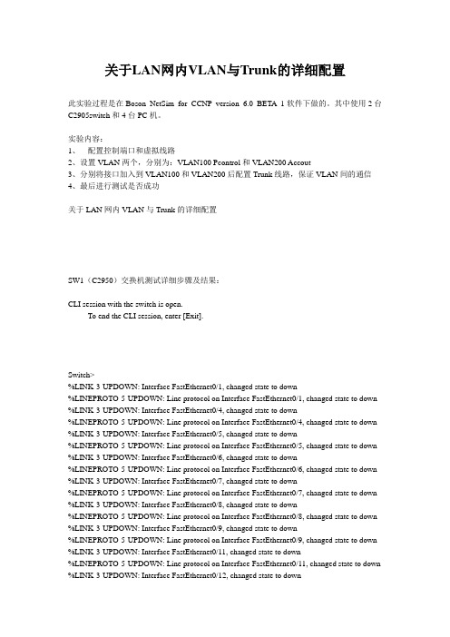
关于LAN网内VLAN与Trunk的详细配置此实验过程是在Boson NetSim for CCNP version 6.0 BETA 1软件下做的。
其中使用2台C2905switch和4台PC机。
实验内容:1、配置控制端口和虚拟线路2、设置VLAN两个,分别为:VLAN100 Pcontrol和VLAN200 Accout3、分别将接口加入到VLAN100和VLAN200后配置Trunk线路,保证VLAN间的通信4、最后进行测试是否成功关于LAN网内VLAN与Trunk的详细配置SW1(C2950)交换机测试详细步骤及结果:CLI session with the switch is open.To end the CLI session, enter [Exit].Switch>%LINK-3-UPDOWN: Interface FastEthernet0/1, changed state to down%LINEPROTO-5-UPDOWN: Line protocol on Interface FastEthernet0/1, changed state to down %LINK-3-UPDOWN: Interface FastEthernet0/4, changed state to down%LINEPROTO-5-UPDOWN: Line protocol on Interface FastEthernet0/4, changed state to down %LINK-3-UPDOWN: Interface FastEthernet0/5, changed state to down%LINEPROTO-5-UPDOWN: Line protocol on Interface FastEthernet0/5, changed state to down %LINK-3-UPDOWN: Interface FastEthernet0/6, changed state to down%LINEPROTO-5-UPDOWN: Line protocol on Interface FastEthernet0/6, changed state to down %LINK-3-UPDOWN: Interface FastEthernet0/7, changed state to down%LINEPROTO-5-UPDOWN: Line protocol on Interface FastEthernet0/7, changed state to down %LINK-3-UPDOWN: Interface FastEthernet0/8, changed state to down%LINEPROTO-5-UPDOWN: Line protocol on Interface FastEthernet0/8, changed state to down %LINK-3-UPDOWN: Interface FastEthernet0/9, changed state to down%LINEPROTO-5-UPDOWN: Line protocol on Interface FastEthernet0/9, changed state to down %LINK-3-UPDOWN: Interface FastEthernet0/11, changed state to down%LINEPROTO-5-UPDOWN: Line protocol on Interface FastEthernet0/11, changed state to down %LINK-3-UPDOWN: Interface FastEthernet0/12, changed state to down%LINEPROTO-5-UPDOWN: Line protocol on Interface FastEthernet0/12, changed state to down Switch>enableSwitch#show versionBoson Operating Simulation SoftwareBOSS (tm) C2900 Software (C2900-Enterprise), Version 12.1, RELEASE SOFTWARE Copyright (c) 1998-2003 by Boson Software, Inc.BOSS ROM: System Bootstrap, Version 12.2, RELEASE SOFTWARESwitch Uptime Is 0 days, 0 hours, 0 minutesSystem restarted by power-onSystem image file is ""flash:c2900-enterprise.12.1.boss"", booted via flashBoson 2900 (BOSS) processor (revision 5.0)12 FastEthernet/IEEE 802.3 interface(s)32K bytes of simulated non-volatile configuration memory.8192K bytes of simulated System flash (Read/Write)Switch#Switch#Switch#show runn!Version 12.1service timestamps debug uptimeservice timestamps log uptimeno service password-encryption!hostname Switch!!!ip subnet-zerospanning-tree extend system-id!!!!!!!!interface FastEthernet0/1!interface FastEthernet0/2Switch#show runn!Version 12.1service timestamps debug uptime service timestamps log uptime no service password-encryption !hostname Switch!!!ip subnet-zerospanning-tree extend system-id !!!!!!!!interface FastEthernet0/1!interface FastEthernet0/2!interface FastEthernet0/3!interface FastEthernet0/4!interface FastEthernet0/5!interface FastEthernet0/6!interface FastEthernet0/7!interface FastEthernet0/8!interface FastEthernet0/9!interface FastEthernet0/10!interface FastEthernet0/11interface FastEthernet0/12!vtp domain bigdomain!interface Vlan 1no ip addressno ip route-cache!!ip classlessno ip http server!!!!line con 0transport input noneline aux 0line vty 0 15!no scheduler allocateendSwitch#Switch#Switch#configure terminalEnter configuration commands, one per line. End with CNTL/Z. Switch(config)#hostname SW1SW1(config)#line console 0SW1(config-line)#exec-timeout 20 0SW1(config-line)#logging synchronousSW1(config-line)#password dsfengSW1(config-line)#loginSW1(config-line)#line vty 0 15SW1(config-line)#exec-timeout 15 0SW1(config-line)#logging synchronousSW1(config-line)#password dsfengSW1(config-line)#loginSW1(config-line)#enable secret ciscoSW1(config)#exitSW1#SW1#SW1#vlan databaseSW1(vlan)#vlan 100 name PcontrolVLAN 100 added:Name:PcontrolSW1(vlan)#vlan 200 name AccoutVLAN 200 added:Name:AccoutSW1(vlan)#exitAPPL Y completed.Exiting....SW1#SW1#SW1#configure terminalEnter configuration commands, one per line. End with CNTL/Z.SW1(config)#interface fastethernet 0/2SW1(config-if)#switchport mode accessSW1(config-if)#switchport access vlan 100SW1(config-if)#exitSW1(config)#interface fastethernet 0/3SW1(config-if)#switchport mode accessSW1(config-if)#switchport access vlan 200SW1(config-if)#exitSW1(config)#interface fasteterhent 0/10SW1(config-if)#switchport mode trunkSW1(config-if)#switchport trunk encapsulation dot1qSW1(config-if)#endSW1#SW1#SW1#show interface fastethernet 0/2FastEthernet0/2 is up, line protocol is upHardware is Fast Ethernet, address is 000C.6542.9093 (bia 000C.6542.9093) MTU 1500 bytes, BW 10000 Kbit, DL Y 1000 usec,reliability 255/255, txload 1/255, rxload 1/255Auto-duplex, Auto-speedEncapsulation ARPA, loopback not setARP type: ARPA, ARP Timeout 04:00:00Last input 02:29:44, output never, output hang neverLast clearing of "show interface" counters neverInput queue: 0/75/0/0 (size/max/drops/flushes); Total output drops: 0 Queueing strategy: fifoOutput queue :0/40 (size/max)5 minute input rate 0 bits/sec, 0 packets/sec5 minute output rate 0 bits/sec, 0 packets/sec269 packets input, 71059 bytes, 0 no bufferReceived 6 broadcasts, 0 runts, 0 giants, 0 throttles0 input errors, 0 CRC, 0 frame, 0 overrun, 0 ignored7290 packets output, 429075 bytes, 0 underruns0 output errors, 3 interface resets0 output buffer failures, 0 output buffers swapped outSW1#SW1#SW1#show interface fastethernet 0/3FastEthernet0/3 is up, line protocol is upHardware is Fast Ethernet, address is 000C.3849.2796 (bia 000C.3849.2796) MTU 1500 bytes, BW 10000 Kbit, DL Y 1000 usec,reliability 255/255, txload 1/255, rxload 1/255Auto-duplex, Auto-speedEncapsulation ARPA, loopback not setARP type: ARPA, ARP Timeout 04:00:00Last input 02:29:44, output never, output hang neverLast clearing of "show interface" counters neverInput queue: 0/75/0/0 (size/max/drops/flushes); Total output drops: 0 Queueing strategy: fifoOutput queue :0/40 (size/max)5 minute input rate 0 bits/sec, 0 packets/sec5 minute output rate 0 bits/sec, 0 packets/sec269 packets input, 71059 bytes, 0 no bufferReceived 6 broadcasts, 0 runts, 0 giants, 0 throttles0 input errors, 0 CRC, 0 frame, 0 overrun, 0 ignored7290 packets output, 429075 bytes, 0 underruns0 output errors, 3 interface resets0 output buffer failures, 0 output buffers swapped outSW1#SW1#SW1#show interface fastethernet 0/10FastEthernet0/10 is up, line protocol is upHardware is Fast Ethernet, address is 000C.3878.9745 (bia 000C.3878.9745) MTU 1500 bytes, BW 10000 Kbit, DL Y 1000 usec,reliability 255/255, txload 1/255, rxload 1/255Auto-duplex, Auto-speedEncapsulation ARPA, loopback not setARP type: ARPA, ARP Timeout 04:00:00Last input 02:29:44, output never, output hang neverLast clearing of "show interface" counters neverInput queue: 0/75/0/0 (size/max/drops/flushes); Total output drops: 0 Queueing strategy: fifoOutput queue :0/40 (size/max)5 minute input rate 0 bits/sec, 0 packets/sec5 minute output rate 0 bits/sec, 0 packets/sec269 packets input, 71059 bytes, 0 no bufferReceived 6 broadcasts, 0 runts, 0 giants, 0 throttles0 input errors, 0 CRC, 0 frame, 0 overrun, 0 ignored7290 packets output, 429075 bytes, 0 underruns0 output errors, 3 interface resets0 output buffer failures, 0 output buffers swapped outSW1#SW1#SW1#show vlanVLAN Name Status Ports---- -------------------------------- --------- -------------------------------1 default active Fa0/1, Fa0/4, Fa0/5, Fa0/6Fa0/7, Fa0/8, Fa0/9, Fa0/10Fa0/11, Fa0/12100 Pcontrol active Fa0/2200 Accout active Fa0/31002 fddi-default active1003 token-ring-default active1004 fddinet-default active1005 trnet-default activeVLAN Type SAID MTU Parent RingNo BridgeNo Stp BrdgMode Trans1 Trans2 ---- ----- ---------- ----- ------ ------ -------- ---- -------- ------ ------1 enet 100001 1500 - - - - - 0 0100 enet 100100 1500 - - - - - 0 0200 enet 100200 1500 - - - - - 0 01002 fddi 101002 1500 - - - - - 0 01003 tr 101003 1500 - - - - - 0 01004 fdnet 101004 1500 - - - ieee - 0 01005 trnet 101005 1500 - - - ibm - 0 0SW1#SW1#SW1#show cdp neighborsCapability Codes: R - Router, T - Trans Bridge, B - Source Route BridgeS -Switch, H - Host, i - IGMP, r - RepeaterDevice ID Local Intrfce Holdtme Capability Platform Port IDSW2 Fas0/10 167 T S 2950 Fas 0/10SW1#SW1#SW1#show mac-address-tableCapability Codes: R - Router, T - Trans Bridge, B - Source Route BridgeS -Switch, H - Host, i - IGMP, r - RepeaterDevice ID Local Intrfce Holdtme Capability Platform Port IDSW2 Fas0/10 167 T S 2950 Fas 0/10Mac Address Table------------------------------------------Vlan Mac Address Type Ports---- ----------- ---- -----200 000C.9631.1997 DYNAMIC Fa0/3100 000C.7036.8702 DYNAMIC Fa0/21 000C.3817.8412 DYNAMIC Fa0/101 000C.9623.5011 DYNAMIC Fa0/101 000C.1738.3819 DYNAMIC Fa0/10Total Mac Addresses for this criterion: 5SW1#SW1#SW1#show run!Version 12.1service timestamps debug uptimeservice timestamps log uptimeno service password-encryption!hostname SW1enable secret 5 $sdf$6978yhg$jnb76sd!!!ip subnet-zerospanning-tree extend system-id!!!!!!!!interface FastEthernet0/1!interface FastEthernet0/2 switchport mode access switchport access vlan 100!interface FastEthernet0/3 switchport mode access switchport access vlan 200!interface FastEthernet0/4!interface FastEthernet0/5!interface FastEthernet0/6!interface FastEthernet0/7!interface FastEthernet0/8!interface FastEthernet0/9!interface FastEthernet0/10 switchport mode trunkswitchport trunk encapsulation dot1q !interface FastEthernet0/11!interface FastEthernet0/12!vtp domain bigdomain!interface Vlan 1no ip addressno ip route-cache!vlan 100 name Pcontrolvlan 200 name Accout!ip classlessno ip http server!!!!line con 0logintransport input nonepassword dsfengexec-timeout 15 0logging synchronousline aux 0line vty 0 15loginpassword dsfeng!no scheduler allocateendSW1#SW1#SW1#copy running-config startup-configDestination filename [startup-config]?Building configuration...[OK]SW1#SW1#SW2(C2950)交换机测试详细步骤及结果:CLI session with the switch is open.To end the CLI session, enter [Exit].%LINK-3-UPDOWN: Interface FastEthernet0/1, changed state to down%LINEPROTO-5-UPDOWN: Line protocol on Interface FastEthernet0/1, changed state to down %LINK-3-UPDOWN: Interface FastEthernet0/4, changed state to down%LINEPROTO-5-UPDOWN: Line protocol on Interface FastEthernet0/4, changed state to down %LINK-3-UPDOWN: Interface FastEthernet0/5, changed state to down%LINEPROTO-5-UPDOWN: Line protocol on Interface FastEthernet0/5, changed state to down %LINK-3-UPDOWN: Interface FastEthernet0/6, changed state to down%LINEPROTO-5-UPDOWN: Line protocol on Interface FastEthernet0/6, changed state to down %LINK-3-UPDOWN: Interface FastEthernet0/7, changed state to down%LINEPROTO-5-UPDOWN: Line protocol on Interface FastEthernet0/7, changed state to down %LINK-3-UPDOWN: Interface FastEthernet0/8, changed state to down%LINEPROTO-5-UPDOWN: Line protocol on Interface FastEthernet0/8, changed state to down %LINK-3-UPDOWN: Interface FastEthernet0/9, changed state to down%LINEPROTO-5-UPDOWN: Line protocol on Interface FastEthernet0/9, changed state to down %LINK-3-UPDOWN: Interface FastEthernet0/11, changed state to down%LINEPROTO-5-UPDOWN: Line protocol on Interface FastEthernet0/11, changed state to down %LINK-3-UPDOWN: Interface FastEthernet0/12, changed state to down%LINEPROTO-5-UPDOWN: Line protocol on Interface FastEthernet0/12, changed state to down Switch>Switch>enableSwitch#show versionBoson Operating Simulation SoftwareBOSS (tm) C2900 Software (C2900-Enterprise), Version 12.1, RELEASE SOFTWARE Copyright (c) 1998-2003 by Boson Software, Inc.BOSS ROM: System Bootstrap, Version 12.2, RELEASE SOFTWARESwitch Uptime Is 0 days, 0 hours, 5 minutesSystem restarted by power-onSystem image file is ""flash:c2900-enterprise.12.1.boss"", booted via flashBoson 2900 (BOSS) processor (revision 5.0)12 FastEthernet/IEEE 802.3 interface(s)32K bytes of simulated non-volatile configuration memory.8192K bytes of simulated System flash (Read/Write)Switch#Switch#Switch#show runn!Version 12.1service timestamps debug uptimeservice timestamps log uptimeno service password-encryption!hostname Switch!!!ip subnet-zerospanning-tree extend system-id !!!!!!!!interface FastEthernet0/1!interface FastEthernet0/2!interface FastEthernet0/3!interface FastEthernet0/4!interface FastEthernet0/5!interface FastEthernet0/6!interface FastEthernet0/7!interface FastEthernet0/8!interface FastEthernet0/9!interface FastEthernet0/10!interface FastEthernet0/11!interface FastEthernet0/12!vtp domain bigdomain!interface Vlan 1no ip addressno ip route-cache!!ip classlessno ip http server!!!!line con 0transport input noneline aux 0line vty 0 15!no scheduler allocateendSwitch#Switch#Switch#configure terminalEnter configuration commands, one per line. End with CNTL/Z. Switch(config)#hostname SW2SW2(config)#line console 0SW2(config-line)#exec-timeout 20 0SW2(config-line)#logging synchronousSW2(config-line)#password dsfengSW2(config-line)#loginSW2(config-line)#line vty 0 15SW2(config-line)#exec-timeout 15 0SW2(config-line)#logging synchronousSW2(config-line)#password dsfengSW2(config-line)#loginSW2(config-line)#enable secret ciscoSW2(config)#endSW2#SW2#SW2#vlan databaseSW2(vlan)#vlan 100 name PcontrolVLAN 100 added:Name:PcontrolSW2(vlan)#vlan 200 name AccoutVLAN 200 added:Name:AccoutSW2(vlan)#exitAPPL Y completed.Exiting....SW2#SW2#SW2#configure terminalEnter configuration commands, one per line. End with CNTL/Z.SW2(config)#interface fastethernet 0/2SW2(config-if)#switchport mode accessSW2(config-if)#switchport access vlan 100SW2(config-if)#exitSW2(config)#interface fastethernet 0/3SW2(config-if)#switchport mode accessSW2(config-if)#switchport access vlan 200SW2(config-if)#exitSW2(config)#interface fastethernet 0/10SW2(config-if)#switchport mode trunkSW2(config-if)#switchport trunk encapsulation dot1qSW2(config-if)#endSW2#SW2#SW2#show interface fastethernet 0/2FastEthernet0/2 is up, line protocol is upHardware is Fast Ethernet, address is 000C.2018.9057 (bia 000C.2018.9057) MTU 1500 bytes, BW 10000 Kbit, DL Y 1000 usec,reliability 255/255, txload 1/255, rxload 1/255Auto-duplex, Auto-speedEncapsulation ARPA, loopback not setARP type: ARPA, ARP Timeout 04:00:00Last input 02:29:44, output never, output hang neverLast clearing of "show interface" counters neverInput queue: 0/75/0/0 (size/max/drops/flushes); Total output drops: 0 Queueing strategy: fifoOutput queue :0/40 (size/max)5 minute input rate 0 bits/sec, 0 packets/sec5 minute output rate 0 bits/sec, 0 packets/sec269 packets input, 71059 bytes, 0 no bufferReceived 6 broadcasts, 0 runts, 0 giants, 0 throttles0 input errors, 0 CRC, 0 frame, 0 overrun, 0 ignored7290 packets output, 429075 bytes, 0 underruns0 output errors, 3 interface resets0 output buffer failures, 0 output buffers swapped outSW2#SW2#SW2#show interface fastethernet 0/3FastEthernet0/3 is up, line protocol is upHardware is Fast Ethernet, address is 000C.4287.4991 (bia 000C.4287.4991) MTU 1500 bytes, BW 10000 Kbit, DL Y 1000 usec,reliability 255/255, txload 1/255, rxload 1/255Auto-duplex, Auto-speedEncapsulation ARPA, loopback not setARP type: ARPA, ARP Timeout 04:00:00Last input 02:29:44, output never, output hang neverLast clearing of "show interface" counters neverInput queue: 0/75/0/0 (size/max/drops/flushes); Total output drops: 0 Queueing strategy: fifoOutput queue :0/40 (size/max)5 minute input rate 0 bits/sec, 0 packets/sec5 minute output rate 0 bits/sec, 0 packets/sec269 packets input, 71059 bytes, 0 no bufferReceived 6 broadcasts, 0 runts, 0 giants, 0 throttles0 input errors, 0 CRC, 0 frame, 0 overrun, 0 ignored7290 packets output, 429075 bytes, 0 underruns0 output errors, 3 interface resets0 output buffer failures, 0 output buffers swapped outSW2#SW2#SW2#show interface fastethernet 0/10FastEthernet0/10 is up, line protocol is upHardware is Fast Ethernet, address is 000C.3817.8412 (bia 000C.3817.8412) MTU 1500 bytes, BW 10000 Kbit, DL Y 1000 usec,reliability 255/255, txload 1/255, rxload 1/255Auto-duplex, Auto-speedEncapsulation ARPA, loopback not setARP type: ARPA, ARP Timeout 04:00:00Last input 02:29:44, output never, output hang neverLast clearing of "show interface" counters neverInput queue: 0/75/0/0 (size/max/drops/flushes); Total output drops: 0 Queueing strategy: fifoOutput queue :0/40 (size/max)5 minute input rate 0 bits/sec, 0 packets/sec5 minute output rate 0 bits/sec, 0 packets/sec269 packets input, 71059 bytes, 0 no bufferReceived 6 broadcasts, 0 runts, 0 giants, 0 throttles0 input errors, 0 CRC, 0 frame, 0 overrun, 0 ignored7290 packets output, 429075 bytes, 0 underruns0 output errors, 3 interface resets0 output buffer failures, 0 output buffers swapped outSW2#SW2#SW2#show vlanVLAN Name Status Ports---- -------------------------------- --------- -------------------------------1 default active Fa0/1, Fa0/4, Fa0/5, Fa0/6Fa0/7, Fa0/8, Fa0/9, Fa0/10Fa0/11, Fa0/12100 Pcontrol active Fa0/2200 Accout active Fa0/31002 fddi-default active1003 token-ring-default active1004 fddinet-default active1005 trnet-default activeVLAN Type SAID MTU Parent RingNo BridgeNo Stp BrdgMode Trans1 Trans2 ---- ----- ---------- ----- ------ ------ -------- ---- -------- ------ ------1 enet 100001 1500 - - - - - 0 0100 enet 100100 1500 - - - - - 0 0200 enet 100200 1500 - - - - - 0 01002 fddi 101002 1500 - - - - - 0 01003 tr 101003 1500 - - - - - 0 01004 fdnet 101004 1500 - - - ieee - 0 01005 trnet 101005 1500 - - - ibm - 0 0SW2#SW2#SW2#show mac-address-tableVLAN Name Status Ports---- -------------------------------- --------- -------------------------------1 default active Fa0/1, Fa0/4, Fa0/5, Fa0/6Fa0/7, Fa0/8, Fa0/9, Fa0/10Fa0/11, Fa0/12100 Pcontrol active Fa0/2200 Accout active Fa0/31002 fddi-default active1003 token-ring-default active1004 fddinet-default active1005 trnet-default activeVLAN Type SAID MTU Parent RingNo BridgeNo Stp BrdgMode Trans1 Trans2 ---- ----- ---------- ----- ------ ------ -------- ---- -------- ------ ------1 enet 100001 1500 - - - - - 0 0100 enet 100100 1500 - - - - - 0 0 200 enet 100200 1500 - - - - - 0 0 1002 fddi 101002 1500 - - - - - 0 0 1003 tr 101003 1500 - - - - - 0 0 1004 fdnet 101004 1500 - - - ieee - 0 0 1005 trnet 101005 1500 - - - ibm - 0 0Mac Address Table------------------------------------------Vlan Mac Address Type Ports---- ----------- ---- -----200 000C.1738.3819 DYNAMIC Fa0/3100 000C.9623.5011 DYNAMIC Fa0/21 000C.3878.9745 DYNAMIC Fa0/101 000C.7036.8702 DYNAMIC Fa0/101 000C.9631.1997 DYNAMIC Fa0/10Total Mac Addresses for this criterion: 5SW2#SW2#SW2#show runn!Version 12.1service timestamps debug uptimeservice timestamps log uptimeno service password-encryption!hostname SW2enable secret 5 $sdf$6978yhg$jnb76sd!!!ip subnet-zerospanning-tree extend system-id!!!!!!!!interface FastEthernet0/1!interface FastEthernet0/2 switchport mode access switchport access vlan 100!interface FastEthernet0/3 switchport mode access switchport access vlan 200!interface FastEthernet0/4!interface FastEthernet0/5!interface FastEthernet0/6!interface FastEthernet0/7!interface FastEthernet0/8!interface FastEthernet0/9!interface FastEthernet0/10 switchport mode trunkswitchport trunk encapsulation dot1q !interface FastEthernet0/11!interface FastEthernet0/12!vtp domain bigdomain!interface Vlan 1no ip addressno ip route-cache!vlan 100 name Pcontrolvlan 200 name Accout!ip classlessno ip http server!!!!line con 0logintransport input nonepassword dsfengexec-timeout 15 0logging synchronousline aux 0line vty 0 15loginpassword dsfeng!no scheduler allocateendSW2#SW2#SW2#copy running-config startup-configDestination filename [startup-config]?Building configuration...[OK]SW2#SW2#PC1测试结果:Boson BOSS 5.0Copyright 1998-2005 Boson Software, Inc.Use the command help to get startedPress Enter to beginC:>C:>ipconfig /ip 192.168.1.1 255.255.255.0C:>ping 192.168.1.2Pinging 192.168.1.2 with 32 bytes of data:Reply from 192.168.1.2: bytes=32 time=60ms TTL=241 Reply from 192.168.1.2: bytes=32 time=60ms TTL=241Reply from 192.168.1.2: bytes=32 time=60ms TTL=241Reply from 192.168.1.2: bytes=32 time=60ms TTL=241Reply from 192.168.1.2: bytes=32 time=60ms TTL=241Ping statistics for 192.168.1.2: Packets: Sent = 5, Received = 5, Lost = 0 (0% loss), Approximate round trip times in milli-seconds:Minimum = 50ms, Maximum = 60ms, Average = 55msPC2测试结果:Boson BOSS 5.0Copyright 1998-2005 Boson Software, Inc.Use the command help to get startedPress Enter to beginC:>ipconfig /ip 192.168.10.1 255.255.255.0C:>C:>ping 192.168.10.2Pinging 192.168.10.2 with 32 bytes of data:Reply from 192.168.10.2: bytes=32 time=60ms TTL=241Reply from 192.168.10.2: bytes=32 time=60ms TTL=241Reply from 192.168.10.2: bytes=32 time=60ms TTL=241Reply from 192.168.10.2: bytes=32 time=60ms TTL=241Reply from 192.168.10.2: bytes=32 time=60ms TTL=241Ping statistics for 192.168.10.2: Packets: Sent = 5, Received = 5, Lost = 0 (0% loss), Approximate round trip times in milli-seconds:Minimum = 50ms, Maximum = 60ms, Average = 55msPC3测试结果:Boson BOSS 5.0Copyright 1998-2005 Boson Software, Inc.Use the command help to get startedPress Enter to beginC:>ipconfig /ip 192.168.1.2 255.255.255.0C:>ping 192.168.1.1Pinging 192.168.1.1 with 32 bytes of data:Reply from 192.168.1.1: bytes=32 time=60ms TTL=241Reply from 192.168.1.1: bytes=32 time=60ms TTL=241Reply from 192.168.1.1: bytes=32 time=60ms TTL=241Reply from 192.168.1.1: bytes=32 time=60ms TTL=241Reply from 192.168.1.1: bytes=32 time=60ms TTL=241Ping statistics for 192.168.1.1: Packets: Sent = 5, Received = 5, Lost = 0 (0% loss), Approximate round trip times in milli-seconds:Minimum = 50ms, Maximum = 60ms, Average = 55msPC4测试结果:Boson BOSS 5.0Copyright 1998-2005 Boson Software, Inc.Use the command help to get startedPress Enter to beginC:>ipconfig /ip 192.168.10.2 255.255.255.0C:>ping 192.168.10.1Pinging 192.168.10.1 with 32 bytes of data:Reply from 192.168.10.1: bytes=32 time=60ms TTL=241Reply from 192.168.10.1: bytes=32 time=60ms TTL=241Reply from 192.168.10.1: bytes=32 time=60ms TTL=241Reply from 192.168.10.1: bytes=32 time=60ms TTL=241Reply from 192.168.10.1: bytes=32 time=60ms TTL=241Ping statistics for 192.168.10.1: Packets: Sent = 5, Received = 5, Lost = 0 (0% loss), Approximate round trip times in milli-seconds:Minimum = 50ms, Maximum = 60ms, Average = 55ms。
基于trunk端口划分vlan的基本配置

基于trunk端口划分vlan的基本配置基于trunk端口划分VLAN的基本配置是网络管理员必须了解和掌握的重要技能之一。
VLAN(虚拟局域网)是一种将物理网络划分成逻辑上独立的多个网络的技术。
通过将不同的设备和用户分配到不同的VLAN中,可以实现网络资源的灵活分配和管理。
本文将以基于trunk端口划分VLAN的基本配置为主题,逐步回答相关问题,帮助读者了解和掌握这一技能。
一、什么是trunk端口?Trunk端口是一种可以传输多个VLAN数据的端口。
它可以将来自不同VLAN的数据打包封装,通过一个物理链路传输到其他设备,从而实现VLAN之间的通信。
二、为什么需要使用trunk端口?在实际网络中,通常会有多个VLAN,而这些VLAN之间需要进行通信。
如果不使用trunk端口,每个VLAN将被限制在各自的物理链路中,无法实现互相连接。
而使用trunk端口,能够将多个VLAN的数据打包封装在一个物理链路中传输,从而提高网络的灵活性和可管理性。
三、如何配置trunk端口划分VLAN?1. 确认网络拓扑:首先,需要了解网络的拓扑结构,包括设备和链路的连接关系。
2. 配置VLAN:在交换机上创建所需的VLAN,可以通过VLAN ID来标识不同的VLAN。
3. 配置trunk端口:确定哪些端口需要配置为trunk端口。
进入交换机的配置模式,找到相应的端口,输入命令“switchport mode trunk”来将端口配置为trunk模式。
4. 配置允许的VLAN:在trunk端口上,需要配置允许传输的VLAN。
可以使用命令“switchport trunk allowed vlan”+“VLAN ID”的方式来配置允许传输的VLAN,可以同时配置多个VLAN。
5. 验证配置:使用命令“show interfaces trunk”来验证trunk端口的配置,确认配置已经生效。
四、trunk端口配置注意事项1. 确保网络拓扑准确无误:配置trunk端口前,必须清楚网络的拓扑结构,确保理解了各个设备和链路的连接关系,避免配置错误。
华为 VLAN、TRUNK实验笔记记录

配置要求:PC1与PC3之间互通,PC2/PC4之间能互通,PC1与PC2/PC4不能互通,PC2与PC1、PC3不能互通。
LSW1:The device is running!<Huawei><Huawei>u t mInfo: Current terminal monitor is off.<Huawei><Huawei>system-view (进入全局配置模式)Enter system view, return user view with Ctrl+Z.[Huawei][Huawei][Huawei]sy[Huawei]sysname SW1(命名)[SW1][SW1]vlan b[SW1]vlan batch 10 20 (批量创建vlan)Info: This operation may take a few seconds. Please wait for a moment...done.[SW1][SW1]int g[SW1]int GigabitEthernet 0/0/2[SW1-GigabitEthernet0/0/2][SW1-GigabitEthernet0/0/2]port[SW1-GigabitEthernet0/0/2]port link-type?link-type[SW1-GigabitEthernet0/0/2]port link-type ?access Access portdot1q-tunnel QinQ porthybrid Hybrid porttrunk Trunk port[SW1-GigabitEthernet0/0/2]port link-type a[SW1-GigabitEthernet0/0/2]port link-type access (配置交换机接口类型Access)[SW1-GigabitEthernet0/0/2][SW1-GigabitEthernet0/0/2]port d?default discard[SW1-GigabitEthernet0/0/2]port de[SW1-GigabitEthernet0/0/2]port default vl[SW1-GigabitEthernet0/0/2]port default vlan 10 (将接口加入到vlan)[SW1-GigabitEthernet0/0/2][SW1-GigabitEthernet0/0/2]dis this (查看当前配置)#interface GigabitEthernet0/0/2port link-type accessport default vlan 10#return[SW1-GigabitEthernet0/0/2]q[SW1][SW1]int g[SW1]int GigabitEthernet 0/0/3[SW1-GigabitEthernet0/0/3][SW1-GigabitEthernet0/0/3]po[SW1-GigabitEthernet0/0/3]port li[SW1-GigabitEthernet0/0/3]port link-t[SW1-GigabitEthernet0/0/3]port link-type a[SW1-GigabitEthernet0/0/3]port link-type access[SW1-GigabitEthernet0/0/3][SW1-GigabitEthernet0/0/3]po[SW1-GigabitEthernet0/0/3]port d[SW1-GigabitEthernet0/0/3]port de[SW1-GigabitEthernet0/0/3]port default vlan 20[SW1-GigabitEthernet0/0/3][SW1-GigabitEthernet0/0/3]dis this#interface GigabitEthernet0/0/3port link-type accessport default vlan 20#return[SW1-GigabitEthernet0/0/3][SW1-GigabitEthernet0/0/3][SW1-GigabitEthernet0/0/3]q[SW1][SW1][SW1][SW1]int[SW1]interface g[SW1]interface GigabitEthernet 0/0/1[SW1-GigabitEthernet0/0/1]port link-t[SW1-GigabitEthernet0/0/1]port link-type t[SW1-GigabitEthernet0/0/1]port link-type trunk (配置接口类型:trunk)[SW1-GigabitEthernet0/0/1][SW1-GigabitEthernet0/0/1]Mar 13 2017 16:55:39-08:00 SW1 DS/4/DATASYNC_CFGCHANGE:OID 1.3.6.1.4.1.2011.5.25.191.3.1 configurations have been changed. The current change number is 11, thechange loop count is 0, and the maximum number of records is 4095.[SW1-GigabitEthernet0/0/1][SW1-GigabitEthernet0/0/1][SW1-GigabitEthernet0/0/1]dis this (查当前配置)#interface GigabitEthernet0/0/1port link-type trunk#return[SW1-GigabitEthernet0/0/1][SW1-GigabitEthernet0/0/1]port t[SW1-GigabitEthernet0/0/1]port trunk ?allow-pass Allowed vlanpvid Specify current port's PVID VLAN characteristics[SW1-GigabitEthernet0/0/1]port trunk all[SW1-GigabitEthernet0/0/1]port trunk allow-pass vlan 10 20 (允许当前vlan通过此接口)[SW1-GigabitEthernet0/0/1][SW1-GigabitEthernet0/0/1]dis this#interface GigabitEthernet0/0/1port link-type trunkport trunk allow-pass vlan 10 20#return[SW1-GigabitEthernet0/0/1][SW1-GigabitEthernet0/0/1][SW1-GigabitEthernet0/0/1]q[SW1][SW1][SW1][SW1]q<SW1>sa (保存配置)The current configuration will be written to the device.Are you sure to continue?[Y/N]yInfo: Please input the file name ( *.cfg, *.zip ) [vrpcfg.zip]:Mar 13 2017 17:01:30-08:00 SW1 %%01CFM/4/SAVE(l)[0]:The user chose Y when decidi ng whether to save the configuration to the device.<SW1><SW1>dis<SW1>display por<SW1>display port v<SW1>display port vlan (查看vlan接口类型)Port Link Type PVID Trunk VLAN List-------------------------------------------------------------------------------GigabitEthernet0/0/1 trunk 1 1 10 20GigabitEthernet0/0/2 access 10 -GigabitEthernet0/0/3 access 20 -GigabitEthernet0/0/4 hybrid 1 -GigabitEthernet0/0/5 hybrid 1 -GigabitEthernet0/0/6 hybrid 1 -GigabitEthernet0/0/7 hybrid 1 -GigabitEthernet0/0/8 hybrid 1 -GigabitEthernet0/0/9 hybrid 1 -GigabitEthernet0/0/10 hybrid 1 -GigabitEthernet0/0/11 hybrid 1 -GigabitEthernet0/0/12 hybrid 1 -GigabitEthernet0/0/13 hybrid 1 -GigabitEthernet0/0/14 hybrid 1 -GigabitEthernet0/0/15 hybrid 1 -GigabitEthernet0/0/16 hybrid 1 -GigabitEthernet0/0/17 hybrid 1 -GigabitEthernet0/0/18 hybrid 1 -GigabitEthernet0/0/19 hybrid 1 -GigabitEthernet0/0/20 hybrid 1 -GigabitEthernet0/0/21 hybrid 1 -GigabitEthernet0/0/22 hybrid 1 -GigabitEthernet0/0/23 hybrid 1 -GigabitEthernet0/0/24 hybrid 1 -<SW1><SW1><Huawei><Huawei>system-viewEnter system view, return user view with Ctrl+Z.[Huawei][Huawei][SW1][SW1]dis int br (查看接口情况)PHY: Physical*down: administratively down(l): loopback(s): spoofing(b): BFD down(e): ETHOAM down(dl): DLDP down(d): Dampening SuppressedInUti/OutUti: input utility/output utilityInterface PHY Protocol InUti OutUti inErrors outErrors GigabitEthernet0/0/1 up up 0% 0% 0 0 GigabitEthernet0/0/2 up up 0% 0% 0 0 GigabitEthernet0/0/3 up up 0% 0% 0 0 GigabitEthernet0/0/4 down down 0% 0% 0 0 GigabitEthernet0/0/5 down down 0% 0% 0 0 GigabitEthernet0/0/6 down down 0% 0% 0 0 GigabitEthernet0/0/7 down down 0% 0% 0 0 GigabitEthernet0/0/8 down down 0% 0% 0 0 GigabitEthernet0/0/9 down down 0% 0% 0 0 GigabitEthernet0/0/10 down down 0% 0% 0 0 GigabitEthernet0/0/11 down down 0% 0% 0 0 GigabitEthernet0/0/12 down down 0% 0% 0 0 GigabitEthernet0/0/13 down down 0% 0% 0 0 GigabitEthernet0/0/14 down down 0% 0% 0 0 GigabitEthernet0/0/15 down down 0% 0% 0 0 GigabitEthernet0/0/16 down down 0% 0% 0 0 GigabitEthernet0/0/17 down down 0% 0% 0 0 GigabitEthernet0/0/18 down down 0% 0% 0 0 GigabitEthernet0/0/19 down down 0% 0% 0 0 GigabitEthernet0/0/20 down down 0% 0% 0 0 GigabitEthernet0/0/21 down down 0% 0% 0 0 GigabitEthernet0/0/22 down down 0% 0% 0 0 GigabitEthernet0/0/23 down down 0% 0% 0 0 GigabitEthernet0/0/24 down down 0% 0% 0 0 MEth0/0/1 down down 0% 0% 0 0 NULL0 up up(s) 0% 0% 0 0 Vlanif1 up down -- -- 0 0[SW1][SW1][SW1] User interface con0 is availablePlease Press ENTER.---------------------------------------------------------------------------------------------------LSW2The device is running!<Huawei><Huawei>u t mInfo: Current terminal monitor is off.<Huawei><Huawei>sy<Huawei>system-viewEnter system view, return user view with Ctrl+Z.[Huawei][Huawei]sys SW2[SW2][SW2][SW2]v[SW2]vlan b[SW2]vlan batch 10 20Info: This operation may take a few seconds. Please wait for a moment...done. [SW2][SW2][SW2]dis[SW2]display po[SW2]display por[SW2]display port ?vlan Virtual LAN[SW2]display port v[SW2]display port vlanPort Link Type PVID Trunk VLAN List------------------------------------------------------------------------------- GigabitEthernet0/0/1 hybrid 1 -GigabitEthernet0/0/2 hybrid 1 -GigabitEthernet0/0/3 hybrid 1 -GigabitEthernet0/0/4 hybrid 1 -GigabitEthernet0/0/5 hybrid 1 -GigabitEthernet0/0/6 hybrid 1 -GigabitEthernet0/0/7 hybrid 1 -GigabitEthernet0/0/8 hybrid 1 -GigabitEthernet0/0/9 hybrid 1 -GigabitEthernet0/0/10 hybrid 1 -GigabitEthernet0/0/11 hybrid 1 -GigabitEthernet0/0/12 hybrid 1 -GigabitEthernet0/0/13 hybrid 1 -GigabitEthernet0/0/14 hybrid 1 -GigabitEthernet0/0/15 hybrid 1 -GigabitEthernet0/0/16 hybrid 1 -GigabitEthernet0/0/17 hybrid 1 -GigabitEthernet0/0/18 hybrid 1 -GigabitEthernet0/0/19 hybrid 1 -GigabitEthernet0/0/20 hybrid 1 -GigabitEthernet0/0/21 hybrid 1 -GigabitEthernet0/0/22 hybrid 1 -GigabitEthernet0/0/23 hybrid 1 -GigabitEthernet0/0/24 hybrid 1 -[SW2][SW2][SW2]vlan b[SW2]vlan batch 10 20Info: This operation may take a few seconds. Please wait for a moment...done. [SW2][SW2][SW2][SW2]int g[SW2]int GigabitEthernet 0/0/1[SW2-GigabitEthernet0/0/1][SW2-GigabitEthernet0/0/1]por[SW2-GigabitEthernet0/0/1]port lin[SW2-GigabitEthernet0/0/1]port link-t[SW2-GigabitEthernet0/0/1]port link-type t[SW2-GigabitEthernet0/0/1]port link-type trunk[SW2-GigabitEthernet0/0/1][SW2-GigabitEthernet0/0/1]por[SW2-GigabitEthernet0/0/1]port t[SW2-GigabitEthernet0/0/1]port trunk ?allow-pass Allowed vlanpvid Specify current port's PVID VLAN characteristics[SW2-GigabitEthernet0/0/1]port trunk a[SW2-GigabitEthernet0/0/1]port trunk allow-pass vlan 10 20[SW2-GigabitEthernet0/0/1][SW2-GigabitEthernet0/0/1]dis this#interface GigabitEthernet0/0/1port link-type trunkport trunk allow-pass vlan 10 20#return[SW2-GigabitEthernet0/0/1]q[SW2][SW2][SW2]int g0/0/2[SW2-GigabitEthernet0/0/2]por[SW2-GigabitEthernet0/0/2]port lin[SW2-GigabitEthernet0/0/2]port link-t[SW2-GigabitEthernet0/0/2]port link-type a [SW2-GigabitEthernet0/0/2]port link-type access [SW2-GigabitEthernet0/0/2][SW2-GigabitEthernet0/0/2]por[SW2-GigabitEthernet0/0/2]port de[SW2-GigabitEthernet0/0/2]port default v [SW2-GigabitEthernet0/0/2]port default vlan 10 [SW2-GigabitEthernet0/0/2][SW2-GigabitEthernet0/0/2]dis this#interface GigabitEthernet0/0/2port link-type accessport default vlan 10#return[SW2-GigabitEthernet0/0/2]q[SW2][SW2][SW2][SW2]int g0/0/3[SW2-GigabitEthernet0/0/3][SW2-GigabitEthernet0/0/3]por[SW2-GigabitEthernet0/0/3]port lin[SW2-GigabitEthernet0/0/3]port link-t[SW2-GigabitEthernet0/0/3]port link-type a [SW2-GigabitEthernet0/0/3]port link-type access [SW2-GigabitEthernet0/0/3][SW2-GigabitEthernet0/0/3]por[SW2-GigabitEthernet0/0/3]port de[SW2-GigabitEthernet0/0/3]port default v[SW2-GigabitEthernet0/0/3]port default vlan 20[SW2-GigabitEthernet0/0/3][SW2-GigabitEthernet0/0/3]dis this#interface GigabitEthernet0/0/3port link-type accessport default vlan 20#return[SW2-GigabitEthernet0/0/3]q[SW2][SW2][SW2]dis[SW2]display po[SW2]display por[SW2]display port v[SW2]display port vlanPort Link Type PVID Trunk VLAN List ------------------------------------------------------------------------------- GigabitEthernet0/0/1 trunk 1 1 10 20 GigabitEthernet0/0/2 access 10 - GigabitEthernet0/0/3 access 20 - GigabitEthernet0/0/4 hybrid 1 - GigabitEthernet0/0/5 hybrid 1 - GigabitEthernet0/0/6 hybrid 1 - GigabitEthernet0/0/7 hybrid 1 - GigabitEthernet0/0/8 hybrid 1 - GigabitEthernet0/0/9 hybrid 1 - GigabitEthernet0/0/10 hybrid 1 - GigabitEthernet0/0/11 hybrid 1 - GigabitEthernet0/0/12 hybrid 1 - GigabitEthernet0/0/13 hybrid 1 - GigabitEthernet0/0/14 hybrid 1 - GigabitEthernet0/0/15 hybrid 1 - GigabitEthernet0/0/16 hybrid 1 - GigabitEthernet0/0/17 hybrid 1 - GigabitEthernet0/0/18 hybrid 1 - GigabitEthernet0/0/19 hybrid 1 - GigabitEthernet0/0/20 hybrid 1 - GigabitEthernet0/0/21 hybrid 1 - GigabitEthernet0/0/22 hybrid 1 -GigabitEthernet0/0/23 hybrid 1 -GigabitEthernet0/0/24 hybrid 1 -[SW2]q<SW2><SW2>saThe current configuration will be written to the device.Are you sure to continue?[Y/N]yInfo: Please input the file name ( *.cfg, *.zip ) [vrpcfg.zip]:Now saving the current configuration to the slot 0.Save the configuration successfully.<SW2><SW2>----------------------------------------------------------------------------------------------------- ping测试。
Vlan配置和eth-trunk配置实验报告

实验报告班级组号05 联络人组长同组人组成员课程名称计算机网络实验日期10月16日实验名称实验三 Vlan配置和eth-trunk配置成绩实验目的:1.掌握vlan的配置,掌握端口的类型,以及各种端口类型下的vlan配置;2.掌握Eth-trunk的配置,能够创建eth-trunk,并增加eth-trunk成员。
实验条件:计算机、eNSP实验内容:实验拓扑图如下:实验思路:要在各个交换机上配置vlan,SWC的interface Ethernet0/0/1只能通过vlan 10,interface Ethernet0/0/2只能通过vlan 20,其他接口都能通过vlan 10 20.即如下:[SWA]vlan batch 10 20[SWB]vlan batch 10 20[SWC]vlan batch 10 20实验步骤:配置交换机SWC的接口类型以及相应的vlaninterface Ethernet0/0/1要用access型接口,因为它连接的是一台PC机。
它的缺省vlan即为所在vlan。
interface Ethernet0/0/2和接口interface Ethernet0/0/1一样,不同的是它的缺省vlan为20.interface Ethernet0/0/3要用trunk型接口,因为它连接的是交换机。
配置交换机SWA(SWB)时要用到eth-trunkEth-trunk:将多个以太网接口捆绑形成一个逻辑接口以增大带宽和提高设备之间链路的可靠性,保证流量的可靠传输。
配置交换机SWA的接口类型以及相应的vlan(SWB同SWA)interface Ethernet0/0/1要用trunk型接口,因为它连接的是交换机。
interface Ethernet0/0/2和interface Ethernet0/0/3要形成一个逻辑接口eth-trunk,以此来增加带宽,保证可靠性。
测试:SWCSWA(SWB同SWA)Eth-trunk。
华为Eth-trunk链路聚合及VLAN相关命令

stp region-configuration
region-name RG1
instance 1 vlan 1 to 10
instance 2 vlan 11 to 20
active region-configuration
配置实例的优先级:
stp instance 1 priority 4096
stp instance 2 priority 8192
配置相应的交换机为相应实例的根桥:
[SW1]stp instance 2 root primary
[SW1]stp instance 1 root secondary
[S1]quit
S1]interface g0/0/10
[S1]eth-trunk 1
[S1]quit
端口原来是acces要改成Hybrid,要先打port default vlan 1命令,
再打port link-type hybrid命令。
单臂路由的子接口配置示例:
arp-proxy inter-sub-vlan-proxy enabl100
mux-vlan
subordinate separate 20
subordinate group 10
interface GigabitEthernet0/0/1.2
control-vid 20 dot1q-termination
dot1q termination vid 2
ip address 10.0.20.1 255.255.255.0
arp broadcast enable
超级VLAN配 置命令:
VLAN配置Trunk接口

VLAN配置Trunk接⼝实验⼆:配置Trunk接⼝。
实验原理:实验内容:本实验模拟某公司⽹络场景。
公司规模较⼤,员⼯200余名,内部⽹络是-⼀个⼤的局域⽹。
公司放置了多台接⼊交换机(如S1和S2)负责员⼯的⽹络接⼊。
接⼊交换机之间通过汇聚交换机S3相连。
公司通过划分VLAN来隔离⼴播域,由于员⼯较多,相同部门的员⼯通过不同交换机接⼊。
为了保证在不同交换机下相同部门的员⼯能互相通信,需要配置交换机之间链路为⼲道模式,以实现相同VLAN跨交换机通信。
实验拓扑如图:实验编址:第⼀步:基本配置,根据实验编址表进⾏相应的基本I地址配置,并⽤ping命令检测各直连链路的连通性。
在没有完成划分vlan之前各路PC 之间都能互通(属于默认vlan1)这⾥以PC1和PC3的ping测试为例:第⼆步:创建vlan,配置Access⼝公司内⽹需要通过vlan的划分来隔离不同的部门,需要在3台交换机S1、S2、S3上都分别创建vlan10和vlan20,研发部员⼯属于vlan10,市场部门员⼯属于vlan20。
以S2为例,S1、S3相同:配置完成后,使⽤display vlan命令查看所配置的vlan信息,以S1为例:可以观察到相关的vlan都已经配置好了,也可以使⽤display vlan summary 命令查看所配置vlan的简要信息:在S1上配置E 0/0/2和E /0/0/3为Access接⼝,并划分到相应的vlan:在S1上配置E 0/0/3和E /0/0/4为Access接⼝,并划分到相应的vlan:配置完成后,使⽤diaplay port vlan命令检查VLAN 和接⼝配置情况:可以观察到PC所连接的交换机接⼝都已经被配置成access模式,并且已经加⼊到正确的vlan中。
第三步:配置Trunk接⼝将PC所连⼊的交换机接⼝划⼊到相应的部门vlan后,测试相同部门中的PC是否能够通信。
测试PC1和PC3之间的连通性:测试PC2和PC4之间的连通性:可以观察到此时同部门的PC间不能通信。
VLAN配置和Eth-trunk的配置
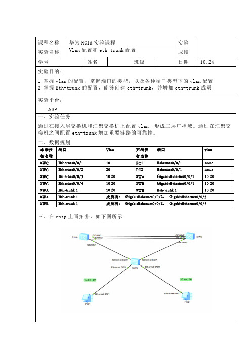
课程名称华为HCIA实验课程实验成绩实验名称Vlan配置和eth-trunk配置学号姓名班级日期10.24实验目的:1.掌握vlan的配置,掌握端口的类型,以及各种端口类型下的vlan配置2.掌握Eth-trunk的配置,能够创建eth-trunk,并增加eth-trunk成员实验平台:ENSP一、实验任务通过在接入层交换机和汇聚交换机上配置vlan,形成二层广播域。
通过在汇聚交换机之间配置eth-trunk增加重要链路的可靠性。
二、数据规划本端设备名称端口Vlan 对端设备名称端口vlanSWC Ethernet0/0/1 10 PC1 Ethernet0/0/1 none SWC Ethernet0/0/2 20 PC2 Ethernet0/0/1 none SWC Ethernet0/0/3 10 20 SWA GigabitEthernet0/0/1 10 20 SWC Ethernet0/0/4 10 20 SWB GigabitEthernet0/0/1 10 20 SWA Eth-trunk 1 10 20 SWB Eth-trunk 1 10 20 SWA Eth-trunk 1 成员有:GigabitEthernet0/0/2、GigabitEthernet0/0/3 SWB Eth-trunk 1 成员有:GigabitEthernet0/0/2、GigabitEthernet0/0/3三、在ensp上画拓扑,如下图所示[SWB]vlan batch 10 20[SWB]interface GigabitEthernet 0/0/1[SWB-GigabitEthernet0/0/1]port link-type trunk[SWB-GigabitEthernet0/0/1]port trunk allow-pass vlan 10 20 [SWB-GigabitEthernet0/0/1]quit[SWB]interface Eth-Trunk 1[SWB-Eth-Trunk1]port link-type trunk[SWB-Eth-Trunk1]port trunk allow-pass vlan 10 20[SWB-Eth-Trunk1]quit[SWB] interface GigabitEthernet 0/0/2[SWB-GigabitEthernet0/0/2]eth-trunk 1[SWB-GigabitEthernet0/0/2]quit[SWB] interface GigabitEthernet 0/0/3[SWB-GigabitEthernet0/0/3]eth-trunk 1[SWB-GigabitEthernet0/0/3]quit[SWB]quit<SWB>save2,通过配置生成了虚拟局域网,并且有两条两路捆绑生成了一条链路。
Trunk详细配置

Trunk基本配置Trunk和Native VLAN举例:1、如果Vlan 2的数据帧要通过Trunk链路发送,并且Trunk又允许Vlan 2通过,那么Trunk在发送该帧前将打上Vlan 2的标记;当对端Trunk链路收到带Vlan 2标记的该数据帧时会剥掉标记,并把该帧交付给Vlan 2。
2、如果Vlan 2是这个Trunk接口的Native Vlan,那么Vlan2的数据帧在进入Trunk链路时,不打标签直接转发。
3、当对端Trunk链路收到一个不带标签的数据帧时(如2中的Native Vlan 2、BPDU帧等),它将会把这个数据帧交付给本地的Native Vlan。
为了可以正确的转发,Trunk链路两端的交换机接口必须配置一致的Native Vlan。
说明:1.在一个交换网络中,帧有两种格式:标记帧(被Trunk打标签)和未标记帧(没被Trunk打标签)。
2.Native VLAN是802.1Q Trunk接口上的概念,在Access口没有Native VLAN 的概念,.默认情况下,Cisco交换机在802.1Q的VLAN封装类型下不对Native VLAN打标签,可以通过“show vlan dot1q tag native”命令查看。
3.Native VLAN的主要的目是不丢弃非标记帧,接收方交换机把所有接收到的未标记的数据帧交付到Native VLAN中,而不是丢弃。
4.默认Native VLAN是Vlan 1,可以通过“show interface trunk”命令来查看;也可以进入Trunk接口,通过“swithport trunk native vlan 2”命令来修改Native Vlan。
5.Trunk链路的两端指定的本征VLAN要一致,否则将导致数据帧从一个VLAN传播到另一个VLAN上。
6.CDP版本2在Cisco交换机之间传送Native VLAN的信息,CDP协议每分钟发送一次数据包。
trunk和access与vlan实验
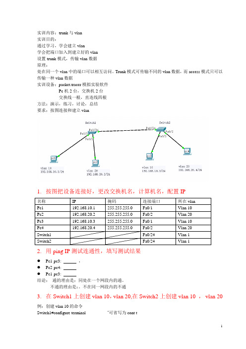
实训内容:trunk与vlan实训目的:通过学习,学会建立vlan学会把端口加入到建立好的vlan设置trunk模式,传输vlan数据原理:处在同一个vlan中的端口可以相互访问。
Trunk模式可传输不同的vlan数据,而access模式只可以传输一种vlan数据实训设备:packet.tracer模拟实验软件Pc机2台,交换机2台交换线一根,直连线四根方法:演示,练习,讨论,总结要求:按图连接和建立vlan1.按图把设备连接好,更改交换机名,计算机名,配置IP2.用ping IP测试连通性,填写测试结果●Pc1-pc3: ,●Pc2-pc4:●Pc1-pc3:结论:通的理由是:同处在一个网段内的通。
不通的理由是:。
不在同一网段内的不通3.在Switch1上创建vlan 10,vlan 20,在Switch2上创建vlan 10 ,vlan 20 例:创建vlan 10的命令Switch1#configure terminal ‘可省写为cont tSwitch1(config)#vlan 10 ‘创建vlan 10Switch1(config-vlan)#exitSwitch1(config)#int vlan 10 ‘进入虚拟端口vlan 10Switch1(config-if)#no shut ‘打开该端口Switch1(config-if)#endSwitch1#show vlan ‘显示创建的vlanVLAN Name Status Ports---- -------------------------------- --------- -------------------------------1 default active Fa0/1, Fa0/2, Fa0/3, Fa0/4●写出在Switch1上创建vlan 20的命令,并创建vlan 20,并显示创建的vlan●用同样的方法,在Switch2上创建vlan 10 , vlan 20,显示vlan●测试连接性Pc1-pc2: ,Pc1-pc3:Pc1-pc4:结论:建立好vlan ,但并没有把vlan加入,结果和没建立好的是一样。
vlan间路由的trunk接口的配置方法
vlan间路由的trunk接口的配置方法VLAN间路由是一种通过Trunk接口实现不同VLAN之间通信的方法。
在本文中,我们将详细介绍如何配置Trunk接口以实现VLAN间路由。
我们需要了解Trunk接口的概念。
Trunk接口是一种可以传输多个VLAN数据的物理或逻辑接口。
它允许在交换机之间传输来自不同VLAN的数据包,从而实现VLAN间路由。
在配置Trunk接口之前,我们需要先创建VLAN并为其分配相应的接口。
假设我们有三个VLAN,分别为VLAN10、VLAN20和VLAN30。
现在我们将为这三个VLAN创建Trunk接口并配置路由。
1. 配置Trunk接口我们需要进入交换机的配置模式。
可以通过命令"enable"进入特权模式,然后再输入"configure terminal"进入全局配置模式。
接下来,我们需要找到Trunk接口的接口编号。
可以使用命令"show interfaces"查看所有接口的状态和编号。
一旦找到了Trunk接口的编号,我们可以使用以下命令来配置Trunk接口:```interface interface编号switchport mode trunk```其中,"interface编号"是我们找到的Trunk接口的编号。
这个命令将接口配置为Trunk模式,使其能够传输多个VLAN的数据。
2. 配置VLAN间路由接下来,我们需要配置VLAN间的路由。
在本例中,我们将使用交换机自带的路由功能来实现。
我们需要创建VLAN接口并将其与相应的VLAN关联。
可以使用以下命令来完成:```interface vlan vlan编号```其中,"vlan编号"是我们要创建的VLAN的编号。
使用这个命令后,我们进入了VLAN接口的配置模式。
然后,我们需要为VLAN接口配置IP地址。
可以使用以下命令来完成:```ip address IP地址子网掩码```其中,"IP地址"是我们要为VLAN接口配置的IP地址,"子网掩码"是相应的子网掩码。
华为交换机端口的trunk属性配置
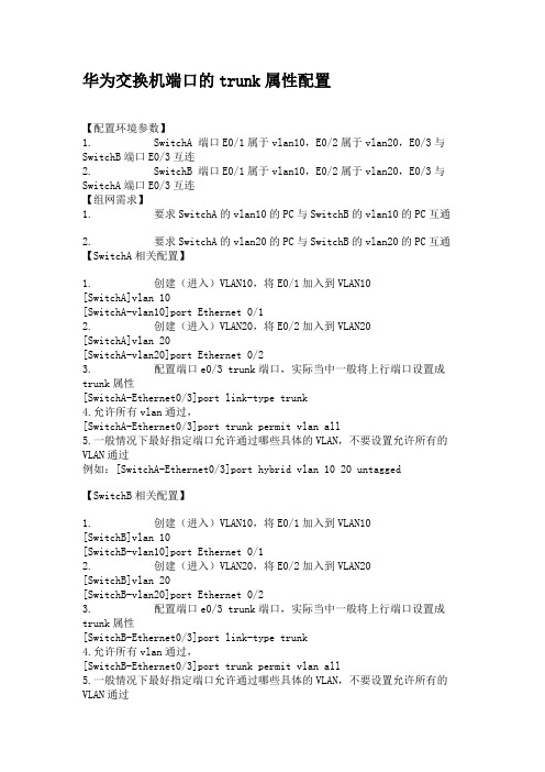
华为交换机端口的trunk属性配置【配置环境参数】1. SwitchA 端口E0/1属于vlan10,E0/2属于vlan20,E0/3与SwitchB端口E0/3互连2. SwitchB 端口E0/1属于vlan10,E0/2属于vlan20,E0/3与SwitchA端口E0/3互连【组网需求】1. 要求SwitchA的vlan10的PC与SwitchB的vlan10的PC互通2. 要求SwitchA的vlan20的PC与SwitchB的vlan20的PC互通【SwitchA相关配置】1. 创建(进入)VLAN10,将E0/1加入到VLAN10[SwitchA]vlan 10[SwitchA-vlan10]port Ethernet 0/12. 创建(进入)VLAN20,将E0/2加入到VLAN20[SwitchA]vlan 20[SwitchA-vlan20]port Ethernet 0/23. 配置端口e0/3 trunk端口,实际当中一般将上行端口设置成trunk属性[SwitchA-Ethernet0/3]port link-type trunk4.允许所有vlan通过,[SwitchA-Ethernet0/3]port trunk permit vlan all5.一般情况下最好指定端口允许通过哪些具体的VLAN,不要设置允许所有的VLAN通过例如:[SwitchA-Ethernet0/3]port hybrid vlan 10 20 untagged【SwitchB相关配置】1. 创建(进入)VLAN10,将E0/1加入到VLAN10[SwitchB]vlan 10[SwitchB-vlan10]port Ethernet 0/12. 创建(进入)VLAN20,将E0/2加入到VLAN20[SwitchB]vlan 20[SwitchB-vlan20]port Ethernet 0/23. 配置端口e0/3 trunk端口,实际当中一般将上行端口设置成trunk属性[SwitchB-Ethernet0/3]port link-type trunk4.允许所有vlan通过,[SwitchB-Ethernet0/3]port trunk permit vlan all5.一般情况下最好指定端口允许通过哪些具体的VLAN,不要设置允许所有的VLAN通过例如:[SwitchB-Ethernet0/3]port hybrid vlan 10 20 untagged【测试验证】1. SwitchA vlan10内的PC可以与SwitchB vlan10内的PC互通2. SwitchA vlan20内的PC可以与SwitchB vlan20内的PC互通3. SwitchA vlan10内的PC不能与SwitchB vlan20内的PC互通4. SwitchA vlan20内的PC不能与SwitchB vlan10内的PC互通【注】1. 如果一个端口是trunk端口,则该端口可以属于多个vlan2. 报文在进入交换机端口时如果没有802.1Q标记将被打上端口的PVID(即defauld vlan ID),之后该数据包就只能在这个vlan域内进行转发,不同的vlan在二层之间是隔离开的,不能实现互相访问。
思科802.1q trunk的VLAN配置
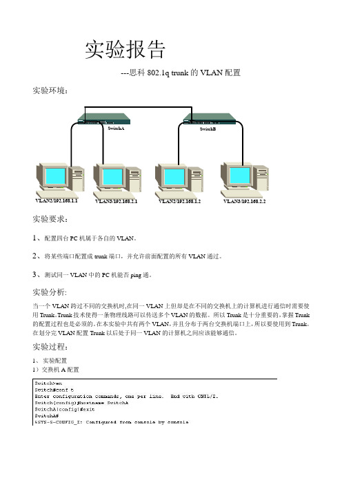
实验报告---思科802.1q trunk的VLAN配置实验环境:实验要求:1、配置四台PC机属于各自的VLAN。
2、将某些端口配置成trunk端口,并允许前面配置的所有VLAN通过。
3、测试同一VLAN中的PC机能否ping通。
实验分析:当一个VLAN跨过不同的交换机时,在同一VLAN上但却是在不同的交换机上的计算机进行通信时需要使用Trunk。
Trunk技术使得一条物理线路可以传送多个VLAN的数据。
所以Trunk是十分重要的,掌握Trunk 的配置过程也是必须的。
在本实验中共有两个VLAN,并且分布于两台交换机端口上,所以要使用到Trunk。
在划分完VLAN配置Trunk以后处于同一VLAN的计算机之间应该能够通信。
实验过程:1、实验配置1)交换机A配置2)交换机B配置3)实验验证4)实验总结本实验的总结我引用的是在网上发现的一篇文章当在交换机上划分有多个VLAN时,若欲借助一条链路实现与其他交换机的通信,就必须要创建Trunk(如图6-13所示)。
默认状态下,第二层接口自动处于动态的Switchport模式,当相邻接口(即借助于双绞线或光纤连接在一起的两个端口)支持Trunk,并且配置为Trunk或动态匹配模式,该链接即可作为Trunk链接。
1.配置Trunk端口进入全局配置模式。
Switch# configure terminal指定欲设置为Trunk的端口。
当然,Trunk应当在交换机级联端口上配置。
Switch(config)# interface interface-id将接口配置为第二层Trunk。
只有接口是第二层访问接口,或者指定Trunk模式时,才需要使用该命令。
dynamic aut o,如果相邻接口被设置为trunk或desirable模式,将该接口置为Trunk连接。
dynamic desirable,如果相邻接口设置为t runk、desirable或auto模式,将该接口置为Trunk连接。
vlan基本命令配置trunk链路配置

vlan基本命令配置trunk链路配置<a target="_blank" href="///wpa/qunwpa?idkey=8a8ad9b8f03685df6bde84370578b288f2a615862defa4f1313567ee78a10858"><img border="0"src="///wpa/images/group.png" alt="IT资料群" title="IT资料群"></a>1 案例1:vlan基本命令1.1 问题1)在交换机上创建vlan10,修改名称为web并查看vlan配置2)删除vlan10,查看vlan配置3)创建vlan20,将端⼝f0/1加⼊此vlan,查看vlan配置4)将f0/1从vlan20中删除,查看vlan配置1.2 步骤实现此案例需要按照如下步骤进⾏步骤⼀:在交换机上创建vlan10,修改名称为web并查看vlan配置1. Switch>enable2. Switch#configure terminal3. Switch(config)#vlan 104. Switch(config-vlan)#name web5. Switch(config-vlan)#end6. Switch#show vlan brief步骤⼆:删除vlan10,查看vlan配置1. Switch#configure terminal2. Switch(config)#no vlan 103. Switch(config)#end4. Switch#show vlan brief步骤三:创建vlan20,将f0/1端⼝加⼊此vlan,查看vlan配置1. Switch#configure terminal2. Switch(config)#vlan 203. Switch(config-vlan)#exit4. Switch(config)#interface fastethernet 0/15. Switch(config-if)#switchport access vlan 206. Switch(config)#end7. Switch#show vlan brief步骤四:将f0/1端⼝从vlan20中删除,查看vlan配置1. Switch#configure terminal2. Switch(config)#interface fastethernet 0/13. Switch(config-if)#no switchport access vlan 204. Switch(config)#end5. Switch#show vlan brief2 2 案例2:vlan基本配置2.1 问题在交换机上创建以下vlan,按照拓扑图-1将端⼝加⼊到指定的vlan并配置服务器IP地址,实现通vlan主机的通信图-12.2 步骤1. Switch>enable2. Switch#configure terminal3. Switch(config)#vlan 24. Switch(config-vlan)#vlan 35. Switch(config-vlan)#exit6. Switch(config)#interface range fastEthernet 0/3-47. Switch(config-if-range)#switchport access vlan 28. Switch(config-vlan)#exit9. Switch(config)#interface range fastEthernet 0/5-610. Switch(config-if-range)#switchport access vlan 311. Switch#show vlan brief3 3 案例3:跨交换机同vlan通信3.1 问题通过配置交换机实现图-2中的vlan主机互通图-23.2 步骤S1配置1. Switch#configure terminal2. Switch(config)#interface fastethernet 0/73. Switch(config-if)#switchport access vlan 3S2配置1. Switch>enable2. Switch#configure terminal3. Switch(config)#vlan 34. Switch(config-vlan)#exit5. Switch(config)#interface range fastEthernet 0/5-76. Switch(config-if-range)#switchport access vlan 34 4 案例4:trunk链路配置4.1 问题如图-3所⽰1)配置s1的f0/1端⼝为trunk模式,分别查看两台交换机f0/1端⼝的状态2)恢复s1的f0/1端⼝为默认模式,分别查看两台交换机f0/1端⼝的状态图-34.2 步骤配置s1的f0/1⼝为trunk模式,分别查看两台交换机f0/1端⼝状态1. Switch>enable2. Switch#configure terminal3. Switch(config)#interface fastEthernet 0/14. Switch(config-if)#switchport mode trunk5. Switch(config-if)#end6. Switch#show interfaces fastEthernet 0/1 switchport恢复s1的f0/1⼝为默认模式,分别查看两台交换机f0/1端⼝状态1. Switch#configure terminal2. Switch(config)#interface fastEthernet 0/13. Switch(config-if)#no switchport mode trunk4. Switch#show interfaces fastEthernet 0/1 switchport5 5 案例5:多vlan跨交换机通信5.1 问题通过配置实现跨交换机的同vlan通信,如图-4所⽰图-45.2 步骤注:以下配置需要在练习3的基础上完成S1配置1. Switch>enable2. Switch#configure terminal3. Switch(config)#interface fastEthernet 0/74. Switch(config-if)#switchport mode trunkS2配置1. Switch>enable2. Switch#configure terminal3. Switch(config)#vlan 24. Switch(config-vlan)#exit5. Switch(config)#interface range fastEthernet 0/3-46. Switch(config-if-range)#switchport access vlan 27. Switch(config-if-range)#exit8. Switch(config)#interface fastEthernet 0/79. Switch(config-if)#switchport mode trunk6 6 案例6:以太⽹通道6.1 问题参照图-5将交换机的f0/7-f0/9端⼝配置为以太⽹通道图-56.2 步骤S1配置1. Switch>enable2. Switch#configure terminal3. Switch(config)#interface range fastEthernet 0/7-94. Switch(config-if-range)#channel-group 1 mode on5. Switch(config-if-range)#end6. Switch#show etherchannel summaryS2配置1. Switch>enable2. Switch#configure terminal3. Switch(config)#interface range fastEthernet 0/7-94. Switch(config-if-range)#channel-group 1 mode on5. Switch(config-if-range)#end6. Switch#show etherchannel summary。
VLAN配置命令

VLAN配置命令vlan 配置思路(access 、Trunk)(1)创建Vlan在基于IOS的交换机上配置静态VLAN:switch# vlan databaseswitch(vlan)# vlan vlan-num name vlan-nameswitch(vlan)# exitswitch# configure teriminalswitch(config)# interface interface module/numberswitch(config-if)# switchport mode access // 设置端口模式为access模式switch(config-if)# switchport access vlan vlan-num // 设置端口所属的VLANswitch(config-if)# end核验配置:show vlan(2)配置干道链路干道是在两台catalyst交换机端口或catalyst交换机与路由器间的一条点对点链路。
干道链路可以承载多个vlan。
在基于IOS的交换机上配置干道链路switch(config)# interface interface mod/portswitch(config-if)# switchport mode trunk // 设置端口模式为trunk模式switch(config-if)# switchport trunk encapsulation {isl|dotlq} // 设置trunk所封装的帧switch(config-if)# switchport trunk allowed vlan remove vlan-list // 允许那些VLAN通过干路no switchportno switchport // 把物理端口变成三层口,即把三层口当成路由器上的口,当将一个端口配置成三层端口之后,就可以在此端口上分配IP地址了,当然还是可以连接PC机的,。
- 1、下载文档前请自行甄别文档内容的完整性,平台不提供额外的编辑、内容补充、找答案等附加服务。
- 2、"仅部分预览"的文档,不可在线预览部分如存在完整性等问题,可反馈申请退款(可完整预览的文档不适用该条件!)。
- 3、如文档侵犯您的权益,请联系客服反馈,我们会尽快为您处理(人工客服工作时间:9:00-18:30)。
步骤三:
• VID里填写要增加的VLAN ID 100,点击增加
•
如下图所示在“删除”的左边有100这个VLAN 选项了。将1-5,21,22,23加入到 VLAN 100里。在下面的“VID号将嵌入到802.1Q标示里”在这里不需要选中2 1,22,23端口的。点击“设置”。
• 下图为VLAN 100在VLAN成员里的变化。
• 如下图为VLAN200的勾选设置。
• 如下图为VLAN300的勾
• 下图为我们设置完VLAN 100,200,300,400后 VLAN成员的显示。此时我们的设置已经完成。
• 下图可以看到VLAN No. 10在VLAN成员里的变化。1-5端 口为VLAN 100;6-10端口为VLAN115;21,22,23端口为tru nk。对11-20端口划分VLAN可参考以上VLAN100和VLAN 115的操作。此时我们的设置已经完成了。
FS2024的FS2024_ V1.8.bin版本配置步骤
• 如下图所示:VLAN NO. 05 和VID 100 对应,选中1-5端 口,将1-5的PVID改为04;21,22,23的的PVID改为00,其 他的不变,点击“设置”。
• 下图为VLAN No. 5在VLAN成员里的变化。
• 如下图所示:VLAN NO. 10 和VID 115 对应,选中6-10端 口,将6-10的PVID改为09;21,22,23的的PVID为00,其 他的不变,点击“设置”。
FS2024 VLAN与TRUNK 配置
• 交换机说明:
1.FS2024出厂默认地址为:192.168.1.1/24,通过第24口进行管理;其 他端口可以ping通192.168.1.1但是管理页面不能打开。 2.登陆的用户名和密码都是admin。在FS2000系列的产品中有登陆用户名 为admin,密码为system的产品。个别产品的用户名是admin,密码是 password。 3.FS2024出厂默认为端口隔离状态,各个端口在同一网段,但是相互间不能 PING通,24口为上联口。 4.目前FS2024的出厂版本和FS2024_SW_V0.7.bin版本配置界面相同, 只能通过第24口管理交换机。最新的FS2024_ V1.8.bin版本每个端口 都可以管理交换机。
• FS2024的出厂版本和FS2024_SW_V0.7.bin 版本的配置步骤: 步骤一:点击“更改模式”更改模式为Tag Ba se Vlan,既基于802.1q的模式。
• 步骤二:1-20口用于接入用户,修改为“删除”标 签,也就是access模式。21,22,23口作为级联口, 修改为“增加”标签,也就是trunk模式。24口不 变,为“忽略”标签,作为管理端口。
如下图在图形界面里显示的是FS2024-V1.0.2
• 步骤一:点击“更改模式”更改模式为Tag Ba se Vlan,既基于802.1q的模式。
• 步骤二:1-20口用于接入用户,修改为“删除”标签,也就 是access模式。21,22,23口作为级联口,修改为“增加” 标签,也就是trunk模式。24口不变,为“忽略”标签,作 为管理端口。这个版本不需要专门用24口做管理口,在端口 数有空闲的情况推荐最后一个口做管理口。
步骤三:
• 1.VLAN NO. 05 和VID 100 的关系就是一种对应 关系,只是方便后期设置。 • 2.VLAN NO. 05 代表:第5个VLAN的VLAN VID 为100,此处的100等同于创建了VLAN 100。 • 3.在Index中,将需要划进VLAN100的端口1-5填 写04(PVID序号等于VLAN NO.-1);Trunk端口 配置成00 • 4.VLAN成员表格可以不做理会,作为参考,可以看 到以前配置的痕迹。 • 5.读取每个VLAN对应的端口配置,可以选择VLAN NO.数值,点击“读取”
