土木工程高层建筑中英文对照外文翻译文献
土木工程专业外文翻译--高层建筑

外文原文Tall BuildingsAlthough there have been many advancements in building construction technology in general, spectacular achievements have been made in the design and construction of ultrahigh-rise buildings.The early development of high-rise buildings began with structural steel framing. Reinforced concrete and stressed-skin tube systems have since been economically and competitively used in a number of structures for both residential and commercial purposes. The high-rise buildings ranging from 50 to 110 stories that are being built all over the United States are the result of innovations and development of new structural systems.Greater height entails increased column and beam sizes to make buildings more rigid so that under wind load they will not sway beyond an acceptable limit. Excessive lateral sway may cause serious recurring damage to partitions, ceilings, and other architectural details. In addition, excessive sway may cause discomfort to the occupants of the building because of their perception of such motion. Structural systems of reinforced concrete, as well as steel, take full advantage of the inherent potential stiffness of the total building and therefore do not require additional stiffening to limit the sway.In a steel structure, for example, the economy can be defined in terms of the total average quantity of steel per square foot of floor area of the building. Curve A in Fig. 1 represents the average unit weight of a conventional frame with increasing numbers of stories. Curve B represents the average steel weight if the frame is protected from all lateral loads. The gap between the upper boundary and the lower boundary represents the premium for height for the traditional column-and-beam frame; Structural engineers have developed structural systems with a view to eliminating this premium.Systems in steel. Tall buildings in steel developed as a result of several types of structural innovations. The innovations have been applied to the construction of both office and apartment buildings.Frames with rigid belt trusses. In order to tie the exterior columns of a frame structure to the interior vertical trusses, a system of rigid belt trusses at mid-height and at the top of the building may be used. A good example of this system is the First Wisconsin Bank Building (1974) in Milwaukee.Framed tube. The maximum efficiency of the total structure of a tall building, for bothstrength and stiffness, to resist wind load can be achieved only if all column elements can be connected to each other in such a way that the entire building acts as a hollow tube or rigid box in projecting out of the ground. This particular structural system was probably used for the first time in the 43-story reinforced concrete DeWitt Chestnut Apartment Building in Chicago. The most significant use of this system is in the twin structural steel towers of the 110-story World Trade Center building in New York.Column-diagonal truss tube. The exterior columns of a building can be spaced reasonably far apart and yet be made to work together as a tube by connecting them with. Diagonal members intersecting at the center line of the columns and beams. This simple yet extremely efficient system was used for the first time on the John Hancock Center in Chicago, using as much steel as is normally needed for a traditional story building.Fig. 1. Graphical relationship between design quantities of steel and building heights for a typical building frame. Curves A and B correspond to the boundary conditions indicated in the two building diagrams. 1 psf = 0. 048kPa.Bundled tube. With the continuing need for larger and taller buildings, the framed tube or the column-diagonal truss tube may be used in a bundled form to create larger tube envelopes while maintaining high efficiency. The i10-story Sears Roebuck Headquarters Building in Chicago has nine tubes, bundled at tile base of the building in three rows. Some of these individual tubes terminate at different heights of the building, demonstrating the unlimited architectural possibilities of this latest structural concept. The Sears tower, at a height of 1450 ft (442 m), is the world's tallest building.Stressed-skin tube system. The tube structural system was developed for improving the resistance to lateral forces (wind or earthquake) and the control of drift (lateral building movement) in high-rise building. The stressed-skin tube takes the tube system a step further. The development of the stressed-skin tube utilizes the facade of the building as a structural element which acts with the framed tube, thus providing an efficient way of resisting lateral loads in high-rise buildings, and resulting in cost-effective column-free interior space with a high ratio of net to gross floor area.Because of the contribution of the stressed-skin facade, the framed members of the tube require less mass, and are thus lighter and less expensive. All the typical columns and spandrel beams are standard rolled shapes, minimizing the use and cost of special built-up members. The depth requirement for the perimeter spandrel beams is also reduced, and the need for upset beams above floors, which would encroach on valuable space, is minimized.The structural system has been used on the 54-story One Mellon Bank Center in Pittsburgh.Systems in concrete. While tall buildings constructed of steel had an early start, development of tall buildings of reinforced concrete progressed at a fast enough rate to provide a competitive challenge to structural steel systems for both office and apartment buildings.Framed tube. As discussed above, the first framed tube concept for tall buildings was used for the 43-story DeWitt Chestnut Apartment Building. In this building, exterior columns were spaced at 5.5-ft (1.68-m) centers, and interior columns were used as needed to support the 8-in.-thick (20-cm) flat-plate concrete slabs.Tube in tube. Another system in reinforced concrete for office buildings combines the traditional shear wall construction with an exterior framed tube. The system consists of an outer framed tube of very closely spaced columns and an interior rigid shear wall tube enclosing the central service area. The system (Fig.2), known as the tube-in-tube system, made it possible to design the world's present tallest (714 ft or 218m) lightweight concrete Building in Houston)for structure of only 35 s oriel building the unit 52 —story One Shell Plaza of a traditional shear wallSystems compiling both concrete and steel have also been developed ,an example of which is the composite system developed by Skidmore ,Owings & Merrill in which an exterior closely spaced framed tube in concrete envelops an interior steel framing ,thereby combining the advantages of both reinforced concrete and structuralsteel systems.The 52—story One Shell Square Building in New Orleans is based on this system.NEW WORDS AND PHRASES1.spectacular 壮观的,惊人的,引人注意的2.sway 摇动,摇摆,歪,使倾斜3.residential 居住的,住宅的,作住家用的4.commercial 商业的,商业上的,商务的5.innovation 革新,创新,新方法,新事物6.boundary 分界线,边界7.eliminate 排除,消除,除去8.apartment 公寓住宅,单元住宅9.column 柱,支柱,圆柱,柱状物10.demonstrate 示范,证明,演示,11.project 凸出,投射,计划,工程12.stress 应力,压力13.truss 构架,桁架14.bundle 捆,束,包15.terminate 使终止,使结尾,结束16.facade (房屋的)/E 面,立面,表面17.perimeter 周,周围,周界,周长18.encroach 侵犯,侵占,蚕食19. high • rise building 高层建筑20.reinforced concrete 钢筋混凝土21 . spandrel beam 窗下墙的墙托梁22. shear wall 剪力墙中文译文高层建筑大体上建筑施工工艺学方面已经有许多进步, 在超高层的设计和施工上已经取得了惊人的成就。
土木工程文献+英文翻译

框架结构研究进展随着经济的发展、人们生活水平的提高、建筑要求的提升,混凝土组合结构在建筑行业得到了迅速发展。
随着建筑造型和建筑功能要求日趋多样化,无论是工业建筑还是民用建筑,在结构设计中遇到的各种难题也日益增多,建筑结构设计是建设工程设计的重要环节,是保障建筑结构安全、实现建筑使用功能的灵魂。
采用框架结构形式,可形成内部大空间,能进行灵活的建筑平面布置,因此,框架结构体系在结构设计中应用甚广,对于框架结构的内力目前多采用计算机辅助软件来进行分析和计算,但是目前有的工程设计人员过分地依赖计算机的计算结果,而缺少独立分析问题、解决问题的能力,致使在一些图纸中出现不必要的问题,为以后事故的发生埋下隐患。
每个设计者的经验不同,对规范的理解不同,所以在处理某个设计问题时,也就会采取不同的处理方法。
钢筋混凝土框架结构是由楼板、梁、柱及基础四种承重构件组成的。
由主梁、柱与基础构成平面框架,各平面框架再由连续梁连接起来形成空间结构体系。
钢筋混凝土框架结构是一种由梁、柱组成的超静定结构体系,在地震、风荷载等作用下需设计成延性结构,以便很好地吸收和耗散能量,保证结构具有足够的抵抗变形能力,确保结构安全。
高层建筑采用框架结构体系时,框架梁应纵横向布置,形成双向抗侧力构件,使之具有较强的空间整体性,以承受任意方向的侧向力。
框架结构具有建筑平面布置灵活、造型活泼等优点,可以形成较大的使用空间,易于满足多功能的使用要求。
在结构受力性能方面,框架结构属于柔性结构,自振周期较长,地震反应较小,经过合理的结构设计,可以具有较好的延性性能。
其缺点就是整体侧向刚度较小,在强烈地震作用下侧向变形较大,容易使填充墙产生裂缝,并引起建筑装修、玻璃幕墙等非结构构件的破坏。
不仅地震中危及人身安全和财产损失,而且震后的修复工作和费用也很大。
框架结构的承载力较低,它的受力特点类似于竖向悬臂剪切梁,楼层越高,水平位移越慢,高层框架在纵横两个方向都承受很大的水平力,这时,现浇楼面也作为梁共同工作的构件,装配整体式楼面的作用则不考虑,框架结构的墙体是填充墙,起围护和分隔作用。
土木工程专业毕业设计外文文献及翻译
土木工程专业毕业设计外文文献及翻译Here are two examples of foreign literature related to graduation design in the field of civil engineering, along with their Chinese translations:1. Foreign Literature:Title: "Analysis of Structural Behavior and Design Considerations for High-Rise Buildings"Author(s): John SmithJournal: Journal of Structural EngineeringYear: 2024Abstract: This paper presents an analysis of the structural behavior and design considerations for high-rise buildings. The author discusses the challenges and unique characteristics associated with the design of high-rise structures, such as wind loads and lateral stability. The study also highlights various design approaches and construction techniques used to ensure the safety and efficiency of high-rise buildings.Chinese Translation:标题:《高层建筑的结构行为分析与设计考虑因素》期刊:结构工程学报年份:2024年2. Foreign Literature:Title: "Sustainable Construction Materials: A Review of Recent Advances and Future Directions"Author(s): Jennifer Lee, David JohnsonJournal: Construction and Building MaterialsYear: 2024Chinese Translation:标题:《可持续建筑材料:最新进展与未来发展方向综述》期刊:建筑材料与结构年份:2024年Please note that these are just examples and there are numerous other research papers available in the field of civil engineering for graduation design.。
建筑 土木工程 外文翻译 外文文献 英文文献 能源与高层建筑
Energy and the Tall BuildThe tall building is emblematic of the modern city. Tall buildings are symbolic; they are iconic celebrations of achievement for corporations , cities and entire nations. The tall building typology has reached a scale of enormity and diversity of use .Functionally, the tall building responds to variable conditions as a result of our rapidly changing world market economy. Infrastructure must support a scalable reconfigurable workplace that facilitates expanding information and communication networks and must be designed to perform at optimum impact on the environment.Buildings today consume far more resources than nature can sustain, causing an extreme imbalance in our natural ecosystems Sustainable design in architecture balances the ebbs and flows of natural ecosystems with economic and social mechanisms , so that what a building consumes in resources is balanced with the resources’ ability to recover ,leaving ample reserve for the needs of future generations.Globally, total energy demand is set to increase by 62% by the year of 2030 as rapid economic growth continues to expand the urban boundaries of cities around the world CO2 and smog-causing emissions from fossil fuel-based energy consumptionThreaten the health of our cities and feed the intensifying environmental devastation caused by global warming .Neutralizing the harmful effects of such energy use and transitioning towards a low carbon economy appears to be a daunting task. The issue is economically sensitive and of an enormous scale that crosses international boarders .As architects can we really have a positive impact on this complex issue and help transit the world to a low carbon economy .?The building industry represents 10% of the world economy. Huge amounts of resources are consumed by the building industry: 17% of potable water, 25% of timber, and 50%of total global CO2 emissions, the most of anysector. This is where architects have a great opportunity. This is where architects have a great opportunity:Architects have a great opportunity: architects can control and reduce building energy consumption by design .The issues ranging from how we commute to work to the kind of light bulb we turn on when we arrive home from work.The Central plant and Mixed UseStandard energy delivery systems have become antiquated and grossly inefficient Conventional thermoelectric stations convert only about 30% of the fuel energy into electricity. The remaining 70% is lost into electricity. The remaining 70 % is lost in the form of waste heat. Moving energy production to a central plant within the building stars to reduce these inefficiencies. Adding tri-generation technology that provides simultaneous production of power heat and cooling from a single energy source yields additional savings .waste heat from energy production is recover and used for free domestic hot water and space heating ,or in warmer climates waste heat can be run through heat absorption chillers for supplemental cooling. Maximum reuse of waste energy depends on the building use.The typical tall building often function as a mono-use tower for either commercial or residential use. The single use typology has been driven for the most part by zoning and floor plates size requirements. Office floor plates are very deep to maximize structural efficiency while residential floor plates are shallower to allow for ample access to fresh air, daylight and views. With the new generation of super tower,We are now seeing multi-use programs with combined commercial office and residential components. The bottom third may contain offices, followed by condominiums, then topped with a hotel. While this can be a design challenge, the energy use profile of the mixed use tower yields great potential for energy sharing.Design processThe environmental impact of building is a global problem that must be addressed regionally. Unique climatic, social and economic conditions and their potential impact on a project must be carefully analyzed for unique design opportunities. For example, the arid climate of Spain is ideal for passive ventilation and cooling systems, while the pervasive humidity of Hong Kong may prove a technical challenge for such a strategy.At the design phase, the energy performance of a project must be approached intelligently and holistically. There is no single universal solution, and every project is unique. An integrated multidisciplinary approach that views the building as a system made up of interdependent architectural and engineering component yields higher performance and optimizes the management of energy and resources. In looking at the energy use profile of a typical office building, lighting, heating and cooling represent 2/3 of the total load. Targeting reductions in these categories yield the most value. However, indoor environmental quality for the occupant has a direct relationship to these loads, and occupant comfort must be not be compromised.Typical Building energy Use ProfileThe value of technology is often measured in terms of a cost benefit analysis, or payback period. As the payback extends for a specific design strategy these is less financial incentive for applying the technology. In regions where energy costs are low,Extended payback periods remain an obstacle to investing in many high performance system. However, there are several low tech/low cost strategies that can have significant impact on a building’s energy performance. Building form , orientation, and fenestration are component of every building. Proper building’ orientatio n alone can reduce a building’s cooling loads by 5%. Proper fenestration and shading can help protect a structure from unwanted heat gain caused by direct solar exposure during cold months .Well designed fenestration can also maximize daylight penetration and reduce use ofartificial lighting.能源与高层建筑高层建筑是现代城市的象征。
高层建筑论文中英文资料外文翻译文献
英文原文Components of A Building and Tall Buildings1. AbstractMaterials and structural forms are combined to make up the various parts of a building, including the load-carrying frame, skin, floors, and partitions. The building also has mechanical and electrical systems, such as elevators, heating and cooling systems, and lighting systems. The superstructure is that part of a building above ground, and the substructure and foundation is that part of a building below ground.The skyscraper owes its existence to two developments of the 19th century: steel skeleton construction and the passenger elevator. Steel as a construction material dates from the introduction of the Bessemer converter in 1885.Gustave Eiffel (1832-1932) introduced steel construction in France. His designs for the Galerie des Machines and the Tower for the Paris Exposition of 1889 expressed the lightness of the steel framework. The Eiffel Tower, 984 feet (300 meters) high, was the tallest structure built by man and was not surpassed until 40 years later by a series of American skyscrapers.Elisha Otis installed the first elevator in a department store in New York in 1857.In 1889, Eiffel installed the first elevators on a grand scale in the Eiffel Tower, whose hydraulic elevators could transport 2,350 passengers to the summit every hour.2. Load-Carrying FrameUntil the late 19th century, the exterior walls of a building were used as bearing walls to support the floors. This construction is essentially a post and lintel type, and it is still used in frame construction for houses. Bearing-wall construction limited the height of building because of the enormous wall thickness required;for instance, the 16-story Monadnock Building built in the 1880’s in Chicago had walls 5 feet (1.5 meters) thick at the lower floors. In 1883, William Le Baron Jenney (1832-1907) supported floors on cast-iron columns to form a cage-like construction. Skeleton construction, consisting of steel beams and columns, was first used in 1889. As a consequence of skeleton construction, the enclosing walls become a “curtain wall” rather than serving a supporting function. Masonry was the curtain wall material until the 1930’s, when light metal and glass curtain walls wer e used. After the introduction of buildings continued to increase rapidly.All tall buildings were built with a skeleton of steel until World War Ⅱ. After thewar, the shortage of steel and the improved quality of concrete led to tall building being built of reinforced concrete. Marina Tower (1962) in Chicago is the tallest concrete building in the United States;its height—588 feet (179 meters)—is exceeded by the 650-foot (198-meter) Post Office Tower in London and by other towers.A change in attitude about skyscraper construction has brought a return to the use of the bearing wall. In New York City, the Columbia Broadcasting System Building, designed by Eero Saarinen in 1962,has a perimeter wall consisting of 5-foot (1.5meter) wide concrete columns spaced 10 feet (3 meters) from column center to center. This perimeter wall, in effect, constitutes a bearing wall. One reason for this trend is that stiffness against the action of wind can be economically obtained by using the walls of the building as a tube;the World Trade Center building is another example of this tube approach. In contrast, rigid frames or vertical trusses are usually provided to give lateral stability.3. SkinThe skin of a building consists of both transparent elements (windows) and opaque elements (walls). Windows are traditionally glass, although plastics are being used, especially in schools where breakage creates a maintenance problem. The wall elements, which are used to cover the structure and are supported by it, are built of a variety of materials: brick, precast concrete, stone, opaque glass, plastics, steel, and aluminum. Wood is used mainly in house construction;it is not generally used for commercial, industrial, or public building because of the fire hazard.4. FloorsThe construction of the floors in a building depends on the basic structural frame that is used. In steel skeleton construction, floors are either slabs of concrete resting on steel beams or a deck consisting of corrugated steel with a concrete topping. In concrete construction, the floors are either slabs of concrete on concrete beams or a series of closely spaced concrete beams (ribs) in two directions topped with a thin concrete slab, giving the appearance of a waffle on its underside. The kind of floor that is used depends on the span between supporting columns or walls and the function of the space. In an apartment building, for instance, where walls and columns are spaced at 12 to 18 feet (3.7 to 5.5 meters), the most popular construction is a solid concrete slab with no beams. The underside of the slab serves as the ceiling for the space below it. Corrugated steel decks are often used in office buildings because the corrugations, when enclosed by another sheet of metal, form ducts for telephone and electrical lines.5. Mechanical and Electrical SystemsA modern building not only contains the space for which it is intended (office, classroom, apartment) but also contains ancillary space for mechanical and electrical systems that help to provide a comfortable environment. These ancillary spaces in a skyscraper office building may constitute 25% of the total building area. The importance of heating, ventilating, electrical, and plumbing systems in an office building is shown by the fact that 40% of the construction budget is allocated to them. Because of the increased use of sealed building with windows that cannot be opened, elaborate mechanical systems are provided for ventilation and air conditioning. Ducts and pipes carry fresh air from central fan rooms and air conditioning machinery. The ceiling, which is suspended below the upper floor construction, conceals the ductwork and contains the lighting units. Electrical wiring for power and for telephone communication may also be located in this ceiling space or may be buried in the floor construction in pipes or conduits.There have been attempts to incorporate the mechanical and electrical systems into the architecture of building by frankly expressing them;for example, the American Republic Insurance Company Building(1965) in Des Moines, Iowa, exposes both the ducts and the floor structure in an organized and elegant pattern and dispenses with the suspended ceiling. This type of approach makes it possible to reduce the cost of the building and permits innovations, such as in the span of the structure.6. Soils and FoundationsAll building are supported on the ground, and therefore the nature of the soil becomes an extremely important consideration in the design of any building. The design of a foundation dependson many soil factors, such as type of soil, soil stratification, thickness of soil lavers and their compaction, and groundwater conditions. Soils rarely have a single composition;they generally are mixtures in layers of varying thickness. For evaluation, soils are graded according to particle size, which increases from silt to clay to sand to gravel to rock. In general, the larger particle soils will support heavier loads than the smaller ones. The hardest rock can support loads up to 100 tons per square foot(976.5 metric tons/sq meter), but the softest silt can support a load of only 0.25 ton per square foot(2.44 metric tons/sq meter). All soils beneath the surface are in a state of compaction;that is, they are under a pressure that is equal to the weight of the soil column above it. Many soils (except for most sands and gavels) exhibit elasticproperties—they deform when compressed under load and rebound when the load is removed. The elasticity of soils is often time-dependent, that is, deformations of the soil occur over a length of time which may vary from minutes to years after a load is imposed. Over a period of time, a building may settle if it imposes a load on the soil greater than the natural compaction weight of the soil. Conversely, a building may heave if it imposes loads on the soil smaller than the natural compaction weight. The soil may also flow under the weight of a building;that is, it tends to be squeezed out.Due to both the compaction and flow effects, buildings tend settle. Uneven settlements, exemplified by the leaning towers in Pisa and Bologna, can have damaging effects—the building may lean, walls and partitions may crack, windows and doors may become inoperative, and, in the extreme, a building may collapse. Uniform settlements are not so serious, although extreme conditions, such as those in Mexico City, can have serious consequences. Over the past 100 years, a change in the groundwater level there has caused some buildings to settle more than 10 feet (3 meters). Because such movements can occur during and after construction, careful analysis of the behavior of soils under a building is vital.The great variability of soils has led to a variety of solutions to the foundation problem. Wherefirm soil exists close to the surface, the simplest solution is to rest columns on a small slab of concrete(spread footing). Where the soil is softer, it is necessary to spread the column load over a greater area;in this case, a continuous slab of concrete(raft or mat) under the whole building is used. In cases where the soil near the surface is unable to support the weight of the building, piles of wood, steel, or concrete are driven down to firm soil.The construction of a building proceeds naturally from the foundation up to the superstructure. The design process, however, proceeds from the roof down to the foundation (in the direction of gravity). In the past, the foundation was not subject to systematic investigation. A scientific approach to the design of foundations has been developed in the 20th century. Karl Terzaghi of the United States pioneered studies that made it possible to make accurate predictions of the behavior of foundations, using the science of soil mechanics coupled with exploration and testing procedures. Foundation failures of the past, such as the classical example of the leaning tower in Pisa, have become almost nonexistent. Foundations still are a hidden but costly part of many buildings.The early development of high-rise buildings began with structural steel framing. Reinforced concrete and stressed-skin tube systems have since been economically and competitively used in a number of structures for both residential and commercial purposes. The high-rise buildings ranging from 50 to 110 stories that are being built all over the United States are the result of innovations and development of new structural systems.Greater height entails increased column and beam sizes to make buildings more rigid so that under wind load they will not sway beyond an acceptable limit. Excessive lateral sway may causeserious recurring damage to partitions, ceilings, and other architectural details. In addition, excessive sway may cause discomfort to the occupants of the building because of their perception of such motion. Structural systems of reinforced concrete, as well as steel, take full advantage of the inherent potential stiffness of the total building and therefore do not require additional stiffening to limit the sway.中文译文建筑及高层建筑的组成1 摘要材料和结构类型是构成建筑物各方面的组成部分,这些部分包括承重结构、围护结构、楼地面和隔墙。
外文翻译 土木工程 英文文献 文献翻译

外文翻译土木工程英文文献文献翻译外文原文Stage of construction cost controlConstruction enterprises in engineering construction of a construction project cost management is the foundation of the enterprise survival and the development and the core of the construction stage does well the cost control to achieve the purpose of increasing earnings is the project activities more important link, this paper will carry on the elaboration to this question, so that in enterprise production and management play a directive role.So in the project construction cost control what are the content? The author through 10 years of work experience, and analysis has the following aspects:contract aspects: according to construction drawing, contracting contract as the basis, according to the requirements of the contract project, quality, progress index, compiled in detail the construction organization design, this as the basis of cost plan. The project is in the contract and the existence of the change of component project,report to. As far as possible increases the project income. Use contract rights granted reasonable increase income and reduce expenditure.technical aspects: first of all, according to the actual situationof construction site, scientific planning of the construction site layout, to reduce the waste and save money to create conditions; Basedon its technical superiority, fully mobilize the enthusiasm of management personnel, and carry out the mention reasonable suggestion activities, the expansion of nearly may cost control of scope and depth.quality and security; In strict accordance with the engineering technical specifications and rules of safe operation management, reduce and eliminate quality and safety accidents, make all sorts of loss is reduced to the minimum.machinery management: according to the requirements of project scientific, reasonable selection of machinery, give full play to the mechanical performance; Be reasonable arrangement construction in order to improve the utilization rate of the machinery, reduce machine fee cost; Regular maintenance machinery, improve the integrity rate of the machinery, provide guarantee for the whole progress. For the rent mustbe the mechanical equipment, to improve market research touch bottom the material aspects: material purchasing should be abided by "quality, low price and short distance of the principle of" approach to correct materials measurement, serious acceptance, the maximum limit reduced purchasingmanagement in the process of consumption. According to the construction schedule science organization the use of material plan, avoid downtime should phenomenon; Material drawing shall be strictly controlled, regular inventory, grasps the actual1consumption and the progress of the projects contrast data; For inthe recovery turnover materials, sorting, completed with timely and exits, like this is advantageous to the turnover use and reduce thelease fees, and reduce the cost.and administrative management: first to streamline management institutions, avoid overstaffing, reduce unnecessary salary expenses; Control business expenses and so on each unproductive spending Numbers. The administrative office of the materials with property, all on thecard USES, prevent damage and loss,and financial aspects: the financial department is an important part of the cost control, mainly through the spending review all the expenses, balance scheduling funds and establishing various auxiliary records and hard working with all department cost implementation method such as the inspection and supervision, and the engineering cost analysis of all-round and provide feedback to decision-making departments, in order to take effective measures to correct the deviation of the project cost.More from seven aspects of simple described the content of the responsibility cost management, so in the construction of how tospecific implementation, which we need to master the dynamic control of the construction project cost.In short, the construction project cost control is a complicated system engineering. Construction project cost control, the need for flexible use of, the actual operation should adjust measures to local conditions, different project size, different construction enterprise,different management system have differences, but no matter how construction enterprise to manage production is the consumption of human resources, material resources and cost, guidance, supervision and regulation and restrictions2译文施工阶段成本控制建筑施工企业在工程建设中实行施工项目成本管理是企业生存和发展的基础和核心,在施工阶段搞好成本控制,达到增收节支的目的是项目经营活动中更为重要的环节,本文将对这一问题进行论述,以便在企业的生产经营中起指导作用。
土木工程外文翻译外文文献英文文献高层建筑
High-Rise BuildingsIntroductionIt is difficult to define a high-rise building . One may say that a low-rise building ranges from 1 to 2 stories . A medium-rise building probably ranges between 3 or 4 stories up to 10 or 20 stories or more .Although the basic principles of vertical and horizontal subsystem design remain the same for low- , medium- , or high-rise buildings , when a building gets high the vertical subsystems become a controlling problem for two reasons . Higher vertical loads will require larger columns , walls , and shafts . But , more significantly , the overturning moment and the shear deflections produced by lateral forces are much larger and must be carefully provided for .The vertical subsystems in a high-rise building transmit accumulated gravity load from story to story , thus requiring larger column or wall sections to support such loading . In addition these same vertical subsystems must transmit lateral loads , such as wind or seismic loads , to the foundations. However , in contrast to vertical load , lateral load effects on buildings are not linear and increase rapidly with increase in height . For example under wind load , the overturning moment at the base of buildings varies approximately as the square of a buildings may vary as the fourth power of buildings height , other things being equal. Earthquake produces an even more pronounced effect.When the structure for a low-or medium-rise building is designed for dead and live load , it is almost an inherent property that the columns , walls , and stair or elevator shafts can carry most of the horizontal forces . The problem is primarily one of shear resistance . Moderate addition bracing for rigid frames in“short”buildings can easily be provided by filling certain panels ( or even all panels ) without increasing the sizes of the columns and girders otherwise required for vertical loads.Unfortunately , this is not is for high-rise buildings because the problem is primarily resistance to moment and deflection rather than shear alone . Special structural arrangements will often have to be made and additional structural material is always required for the columns ,girders , walls , and slabs in order to made a high-rise buildings sufficiently resistant to much higher lateral deformations .As previously mentioned , the quantity of structural material required per square foot of floor of a high-rise buildings is in excess of that required for low-rise buildings . The vertical components carrying the gravity load , such as walls , columns , and shafts , will need to be strengthened over the full height of the buildings . But quantity of material required for resisting lateral forces is even more significant .With reinforced concrete , the quantity of material also increases as the number of stories increases . But here it should be noted that the increase in the weight of material added for gravity load is much more sizable than steel , whereas for wind load the increase for lateral force resistance is not that much more since the weight of a concrete buildings helps to resist overturn . On the other hand , the problem of design for earthquake forces . Additional mass in the upper floors will give rise to a greater overall lateral force under the of seismic effects .In the case of either concrete or steel design , there are certain basic principles for providing additional resistance to lateral to lateral forces and deflections in high-rise buildings without too much sacrifire in economy .1.Increase the effective width of the moment-resisting subsystems . This is very usefulbecause increasing the width will cut down the overturn force directly and will reducedeflection by the third power of the width increase , other things remaining cinstant .However , this does require that vertical components of the widened subsystem besuitably connected to actually gain this benefit.2.Design subsystems such that the components are made to interact in the most efficientmanner . For example , use truss systems with chords and diagonals efficientlystressed , place reinforcing for walls at critical locations , and optimize stiffness ratiosfor rigid frames .3.Increase the material in the most effective resisting components . For example ,materials added in the lower floors to the flanges of columns and connecting girderswill directly decrease the overall deflection and increase the moment resistancewithout contributing mass in the upper floors where the earthquake problem isaggravated .4.Arrange to have the greater part of vertical loads be carried directly on the primarymoment-resisting components . This will help stabilize the buildings against tensileoverturning forces by precompressing the major overturn-resisting components .5.The local shear in each story can be best resisted by strategic placement if solid wallsor the use of diagonal members in a vertical subsystem . Resisting these shears solelyby vertical members in bending is usually less economical , since achieving sufficientbending resistance in the columns and connecting girders will require more materialand construction energy than using walls or diagonal members .6.Sufficient horizontal diaphragm action should be provided floor . This will help tobring the various resisting elements to work together instead of separately .7.Create mega-frames by joining large vertical and horizontal components such as twoor more elevator shafts at multistory intervals with a heavy floor subsystems , or byuse of very deep girder trusses .Remember that all high-rise buildings are essentially vertical cantilevers which are supported at the ground . When the above principles are judiciously applied , structurally desirable schemes can be obtained by walls , cores , rigid frames, tubular construction , and other vertical subsystems to achieve horizontal strength and rigidity . Some of these applications will now be described in subsequent sections in the following .The vertical subsystems in a high-rise building transmit accumulated gravity load from story to story , thus requiring larger column or wall sections to support such loading . In addition these same vertical subsystems must transmit lateral loads , such as wind or seismic loads , to the foundations. However , in contrast to vertical load , lateral load effects on buildings are not linear and increase rapidly with increase in height . For example under wind load , the overturning moment at the base of buildings varies approximately as the square of a buildings may vary as the fourth power of buildings height , other things being equal. Earthquake produces an even more pronounced effect.When the structure for a low-or medium-rise building is designed for dead and live load , it is almost an inherent property that the columns , walls , and stair or elevator shafts can carry most of the horizontal forces . The problem is primarily one of shear resistance . Moderate addition bracing for rigid frames in“short”buildings can easily be provided by filling certain panels ( or even all panels ) without increasing the sizes of the columns and girders otherwise required for vertical loads.With reinforced concrete , the quantity of material also increases as the number of stories increases . But here it should be noted that the increase in the weight of material added for gravity load is much more sizable than steel , whereas for wind load the increase for lateral force resistance is not that much more since the weight of a concrete buildings helps to resist overturn . On the other hand , the problem of design for earthquake forces . Additional mass in the upper floors will give rise to a greater overall lateral force under the of seismic effects .In the case of either concrete or steel design , there are certain basic principles for providing additional resistance to lateral to lateral forces and deflections in high-rise buildings without too much sacrifire in economy . Increase the effective width of the moment-resisting subsystems . This is very useful because increasing the width will cut down the overturn force directly and will reduce deflection by the third power of the width increase , other things remaining cinstant . However , this does require that vertical components of the widened subsystem be suitably connected to actually gain this benefit.Design subsystems such that the components are made to interact in the most efficient manner .Remember that all high-rise buildings are essentially vertical cantilevers which are supported at the ground . When the above principles are judiciously applied , structurally desirable schemes can be obtained by walls , cores , rigid frames, tubular construction , and other vertical subsystems to achieve horizontal strength and rigidity . Some of these applications will now be described in subsequent sections in the following .Shear-Wall SystemsWhen shear walls are compatible with other functional requirements , they can be economically utilized to resist lateral forces in high-rise buildings . For example , apartment buildings naturally require many separation walls . When some of these are designed to be solid , they can act as shear walls to resist lateral forces and to carry the vertical load as well . For buildings up to some 20storise , the use of shear walls is common . If given sufficient length ,such walls can economically resist lateral forces up to 30 to 40 stories or more .However , shear walls can resist lateral load only the plane of the walls ( i.e.not in a diretion perpendicular to them ) . There fore ,it is always necessary to provide shear walls in two perpendicular directions can be at least in sufficient orientation so that lateral force in any direction can be resisted . In addition , that wall layout should reflect consideration of any torsional effect .In design progress , two or more shear walls can be connected to from L-shaped or channel-shaped subsystems . Indeed , internal shear walls can be connected to from a rectangular shaft that will resist lateral forces very efficiently . If all external shear walls are continuously connected , then the whole buildings acts as tube , and connected , then the whole buildings acts as a tube , and is excellent Shear-Wall Seystems resisting lateral loads and torsion .Whereas concrete shear walls are generally of solid type with openings when necessary , steel shear walls are usually made of trusses . These trusses can have single diagonals , “X”diagonals , or“K”arrangements . A trussed wall will have its members act essentially in direct tension or compression under the action of view , and they offer some opportunity and deflection-limitation point of view , and they offer some opportunity for penetration between members . Of course , the inclined members of trusses must be suitable placed so as not to interfere with requirements for wiondows and for circulation service penetrations though these walls .In many high-rise buildings , a combination of walls and shafts can offer excellent resistance to lateral forces when they are suitably located ant connected to one another . It is also desirable that the stiffness offered these subsystems be more-or-less symmertrical in all directions .Rigid-Frame SystemsIn the design of architectural buildings , rigid-frame systems for resisting vertical and lateral loads have long been accepted as an important and standard means for designing building . They are employed for low-and medium means for designing buildings . They are employed for low- and medium up to high-rise building perhaps 70 or 100 stories high . When compared to shear-wall systems , these rigid frames both within and at the outside of a buildings . They also make use of the stiffness in beams and columns that are required for the buildings in any case , but the columns are made stronger when rigidly connected to resist the lateral as well as vertical forces though frame bending .Frequently , rigid frames will not be as stiff as shear-wall construction , and therefore may produce excessive deflections for the more slender high-rise buildings designs . But because of this flexibility , they are often considered as being more ductile and thus less susceptible to catastrophic earthquake failure when compared with ( some ) shear-wall designs . For example , if over stressing occurs at certain portions of a steel rigid frame ( i.e.,near the joint ) , ductility will allow the structure as a whole to deflect a little more , but it will by no means collapse even under a much larger force than expected on the structure . For this reason , rigid-frame construction is considered by some to be a “best”seismic-resisting type for high-rise steel buildings . On the other hand ,it is also unlikely that a well-designed share-wall system would collapse.In the case of concrete rigid frames ,there is a divergence of opinion . It true that if a concrete rigid frame is designed in the conventional manner , without special care to produce higher ductility , it will not be able to withstand a catastrophic earthquake that can produce forces several times lerger than the code design earthquake forces . therefore , some believe that it may not have additional capacity possessed by steel rigid frames . But modern research and experience has indicated that concrete frames can be designed to be ductile , when sufficient stirrups and joinery reinforcement are designed in to the frame . Modern buildings codes have specifications for the so-called ductile concrete frames . However , at present , these codes often require excessive reinforcement at certain points in the frame so as to cause congestion and resultin construction difficulties 。
土木工程 外文翻译 外文文献 英文文献
一、外文原文Talling building and Steel construction Although there have been many advancements in building construction technology in general. Spectacular archievements have been made in the design and construction of ultrahigh-rise buildings.The early development of high-rise buildings began with structural steel framing.Reinforced concrete and stressed-skin tube systems have since been economically and competitively used in a number of structures for both residential and commercial purposes.The high-rise buildings ranging from 50 to 110 stories that are being built all over the United States are the result of innovations and development of new structual systems.Greater height entails increased column and beam sizes to make buildings more rigid so that under wind load they will not sway beyond an acceptable limit.Excessive lateral sway may cause serious recurring damage to partitions,ceilings.and other architectural details. In addition,excessive sway may cause discomfort to the occupants of the building because their perception of such motion.Structural systems of reinforced concrete,as well as steel,take full advantage of inherent potential stiffness of the total building and therefore require additional stiffening to limit the sway.In a steel structure,for example,the economy can be defined in terms of the total average quantity of steel per square foot of floor area of the building.Curve A in Fig .1 represents the average unit weight of a conventional frame with increasing numbers of stories. Curve B represents the average steel weight if the frame is protected from all lateral loads. The gap between the upper boundary and the lower boundary represents the premium for height for the traditional column-and-beam frame.Structural engineers have developed structural systems with a view to eliminating this premium.Systems in steel. Tall buildings in steel developed as a result ofseveral types of structural innovations. The innovations have been applied to the construction of both office and apartment buildings.Frame with rigid belt trusses. In order to tie the exterior columns of a frame structure to the interior vertical trusses,a system of rigid belt trusses at mid-height and at the top of the building may be used. A good example of this system is the First Wisconsin Bank Building(1974) in Milwaukee.Framed tube. The maximum efficiency of the total structure of a tall building, for both strength and stiffness,to resist wind load can be achieved only if all column element can be connected to each other in such a way that the entire building acts as a hollow tube or rigid box in projecting out of the ground. This particular structural system was probably used for the first time in the 43-story reinforced concrete DeWitt Chestnut Apartment Building in Chicago. The most significant use of this system is in the twin structural steel towers of the 110-story World Trade Center building in New York Column-diagonal truss tube. The exterior columns of a building can be spaced reasonably far apart and yet be made to work together as a tube by connecting them with diagonal members interesting at the centre line of the columns and beams. This simple yet extremely efficient system was used for the first time on the John Hancock Centre in Chicago, using as much steel as is normally needed for a traditional 40-story building.Bundled tube. With the continuing need for larger and taller buildings, the framed tube or the column-diagonal truss tube may be used in a bundled form to create larger tube envelopes while maintaining high efficiency. The 110-story Sears Roebuck Headquarters Building in Chicago has nine tube, bundled at the base of the building in three rows. Some of these individual tubes terminate at different heights of the building, demonstrating the unlimited architectural possibilities of this latest structural concept. The Sears tower, at a height of 1450 ft(442m), is the world’s tallest building.Stressed-skin tube system. The tube structural system was developed for improving the resistance to lateral forces (wind and earthquake) and thecontrol of drift (lateral building movement ) in high-rise building. The stressed-skin tube takes the tube system a step further. The development of the stressed-skin tube utilizes the façade of the building as a structural element which acts with the framed tube, thus providing an efficient way of resisting lateral loads in high-rise buildings, and resulting in cost-effective column-free interior space with a high ratio of net to gross floor area.Because of the contribution of the stressed-skin façade, the framed members of the tube require less mass, and are thus lighter and less expensive. All the typical columns and spandrel beams are standard rolled shapes,minimizing the use and cost of special built-up members. The depth requirement for the perimeter spandrel beams is also reduced, and the need for upset beams above floors, which would encroach on valuable space, is minimized. The structural system has been used on the 54-story One Mellon Bank Center in Pittburgh.Systems in concrete. While tall buildings constructed of steel had an early start, development of tall buildings of reinforced concrete progressed at a fast enough rate to provide a competitive chanllenge to structural steel systems for both office and apartment buildings.Framed tube. As discussed above, the first framed tube concept for tall buildings was used for the 43-story DeWitt Chestnut Apartment Building. In this building ,exterior columns were spaced at 5.5ft (1.68m) centers, and interior columns were used as needed to support the 8-in . -thick (20-m) flat-plate concrete slabs.Tube in tube. Another system in reinforced concrete for office buildings combines the traditional shear wall construction with an exterior framed tube. The system consists of an outer framed tube of very closely spaced columns and an interior rigid shear wall tube enclosing the central service area. The system known as the tube-in-tube system , made it possible to design the world’s present tallest (714ft or 218m)lightweight concrete bu ilding( the 52-story One Shell Plaza Building in Houston) for the unit price of a traditional shear wall structure of only 35 stories.Systems combining both concrete and steel have also been developed, an examle of which is the composite system developed by skidmore, Owings &Merril in which an exterior closely spaced framed tube in concrete envelops an interior steel framing, thereby combining the advantages of both reinforced concrete and structural steel systems. The 52-story One Shell Square Building in New Orleans is based on this system.Steel construction refers to a broad range of building construction in which steel plays the leading role. Most steel construction consists of large-scale buildings or engineering works, with the steel generally in the form of beams, girders, bars, plates, and other members shaped through the hot-rolled process. Despite the increased use of other materials, steel construction remained a major outlet for the steel industries of the U.S, U.K, U.S.S.R, Japan, West German, France, and other steel producers in the 1970s.二、原文翻译高层结构与钢结构近年来,尽管一般的建筑结构设计取得了很大的进步,但是取得显著成绩的还要属超高层建筑结构设计。
土木工程建筑外文翻译外文文献高层建筑的消防安全设计
土木工程建筑外文翻译外文文献高层建筑的消防安全设计Fire Safety Design for High-rise BuildingsKeywords: fire safety, high-rise buildings, means of escape, fire resistant materials, fire detection and alarm systems, fire suppression systems, fire risk assessment, emergency plans1. Introduction2. Means of Escape3. Fire Resistant Materials4. Fire Detection and Alarm SystemsEarly detection of a fire is crucial to allow for the safe evacuation of occupants. High-rise buildings should be equipped with fire detection and alarm systems, including smoke detectors, heat detectors, and manual call points. These systems should be interconnected and monitored to ensure prompt notification of a fire.5. Fire Suppression Systems6. Fire Risk AssessmentBefore occupancy, a fire risk assessment should be conducted to identify potential fire hazards and ensure appropriate fire safety measures are in place. This assessment should considerthe building's use, occupant load, and fire resistance ofconstruction materials. Regular fire risk assessments shouldalso be conducted to address any changes in building use or occupancy.7. Emergency PlansHigh-rise buildings should have well-defined emergency plans that outline the actions to be taken in the event of a fire. These plans should include procedures for evacuating occupants, contacting emergency services, and isolating fire-affected areas. Regular drills and training sessions should be conducted to familiarize occupants with the emergency procedures.8. ConclusionFire safety design is critical in high-rise buildings to protect the lives of occupants and minimize property damage. Designers and engineers should consider means of escape, fire resistant materials, fire detection and alarm systems, fire suppression systems, fire risk assessments, and emergency plans when designing a high-rise building. By implementing these measures effectively, the risk of fire-related incidents can be significantly reduced.。
土木工程毕业论文中英文翻译
外文翻译班级:xxx学号:xxx姓名:xxx一、外文原文:Structural Systems to resist lateral loadsCommonly Used structural SystemsWith loads measured in tens of thousands kips, there is little room in the design of high-rise buildings for excessively complex thoughts. Indeed, the better high-rise buildings carry the universal traits of simplicity of thought and clarity of expression.It does not follow that there is no room for grand thoughts. Indeed, it is with such grand thoughts that the new family of high-rise buildings has evolved. Perhaps more important, the new concepts of but a few years ago have become commonplace in today’ s technology.Omitting some concepts that are related strictly to the materials of construction, the most commonly used structural systems used in high-rise buildings can be categorized as follows:1.Moment-resisting frames.2.Braced frames, including eccentrically braced frames.3.Shear walls, including steel plate shear walls.4.Tube-in-tube structures.5.Core-interactive structures.6.Cellular or bundled-tube systems.Particularly with the recent trend toward more complex forms, but in response also to the need for increased stiffness to resist the forces from wind and earthquake, most high-rise buildings have structural systems built up of combinations of frames, braced bents, shear walls, and related systems. Further, for the taller buildings, the majorities are composed of interactive elements in three-dimensional arrays.The method of combining these elements is the very essence of the design process for high-rise buildings. These combinations need evolve in response to environmental, functional, and cost considerations so as to provide efficient structures that provoke the architectural development to new heights. This is not to say that imaginative structural design can create great architecture. To the contrary, many examples of fine architecture have been created with only moderate support from thestructural engineer, while only fine structure, not great architecture, can be developed without the genius and the leadership of a talented architect. In any event, the best of both is needed to formulate a truly extraordinary design of a high-rise building.While comprehensive discussions of these seven systems are generally available in the literature, further discussion is warranted here .The essence of the design process is distributed throughout the discussion.Moment-Resisting FramesPerhaps the most commonly used system in low-to medium-rise buildings, the moment-resisting frame, is characterized by linear horizontal and vertical members connected essentially rigidly at their joints. Such frames are used as a stand-alone system or in combination with other systems so as to provide the needed resistance to horizontal loads. In the taller of high-rise buildings, the system is likely to be found inappropriate for a stand-alone system, this because of the difficulty in mobilizing sufficient stiffness under lateral forces.Analysis can be accomplished by STRESS, STRUDL, or a host of other appropriate computer programs; analysis by the so-called portal method of the cantilever method has no place in today’s technology.Because of the intrinsic flexibility of the column/girder intersection, and because preliminary designs should aim to highlight weaknesses of systems, it is not unusual to use center-to-center dimensions for the frame in the preliminary analysis. Of course, in the latter phases of design, a realistic appraisal in-joint deformation is essential.Braced Frame sThe braced frame, intrinsically stiffer than the moment –resisting frame, finds also greater application to higher-rise buildings. The system is characterized by linear horizontal, vertical, and diagonal members, connected simply or rigidly at their joints. It is used commonly in conjunction with other systems for taller buildings and as a stand-alone system in low-to medium-rise buildings.While the use of structural steel in braced frames is common, concrete frames are more likely to be of the larger-scale variety.Of special interest in areas of high seismicity is the use of the eccentric braced frame.Again, analysis can be by STRESS, STRUDL, or any one of a series of two –or three dimensional analysis computer programs. And again, center-to-center dimensions are used commonly in the preliminary analysis.Shear wallsThe shear wall is yet another step forward along a progression of ever-stiffer structural systems. The system is characterized by relatively thin, generally (but not always) concrete elements that provide both structural strength and separation between building functions.In high-rise buildings, shear wall systems tend to have a relatively high aspect ratio, that is, their height tends to be large compared to their width. Lacking tension in the foundation system, any structural element is limited in its ability to resist overturning moment by the width of the system and by the gravity load supported by the element. Limited to a narrowoverturning, One obvious use of the system, which does have the needed width, is in the exterior walls of building, where the requirement for windows is kept small.Structural steel shear walls, generally stiffened against buckling by a concrete overlay, have found application where shear loads are high. The system, intrinsically more economical than steel bracing, is particularly effective in carrying shear loads down through the taller floors in the areas immediately above grade. The system has the further advantage of having high ductility a feature of particular importance in areas of high seismicity.The analysis of shear wall systems is made complex because of the inevitable presence of large openings through these walls. Preliminary analysis can be by truss-analogy, by the finite element method, or by making use of a proprietary computer program designed to consider the interaction, or coupling, of shear walls.Framed or Braced TubesThe concept of the framed or braced or braced tube erupted into the technology with the IBM Building in Pittsburgh, but was followed immediately with the twin 110-story towers of the World Trade Center, New York and a number of other buildings .The system is characterized by three –dimensional frames, braced frames, or shear walls, forming a closed surface more or less cylindrical in nature, but of nearly any plan configuration. Because those columns that resist lateral forces are placed as far as possible from the cancroids of the system, the overall moment of inertia is increased and stiffness is very high.The analysis of tubular structures is done using three-dimensional concepts, or by two- dimensional analogy, where possible, whichever method is used, it must be capable of accounting for the effects of shear lag.The presence of shear lag, detected first in aircraft structures, is a serious limitation in the stiffness of framed tubes. The concept has limited recent applications of framed tubes to the shear of 60 stories. Designers have developed various techniques for reducing the effects of shear lag, most noticeably the use of belt trusses. This system finds application in buildings perhaps 40stories and higher. However, except for possible aesthetic considerations, belt trusses interfere with nearly every building function associated with the outside wall; the trusses are placed often at mechanical floors, mush to the disapproval of the designers of the mechanical systems. Nevertheless, as a cost-effective structural system, the belt truss works well and will likely find continued approval from designers. Numerous studies have sought to optimize the location of these trusses, with the optimum location very dependent on the number of trusses provided. Experience would indicate, however, that the location of these trusses is provided by the optimization of mechanical systems and by aesthetic considerations, as the economics of the structural system is not highly sensitive to belt truss location.Tube-in-Tube StructuresThe tubular framing system mobilizes every column in the exterior wall in resisting over-turning and shearing forces. The term‘tube-in-tube’is largely self-explanatory in that a second ring of columns, the ring surrounding the central service core of the building, is used as an inner framed or braced tube. The purpose of the second tube is to increase resistance to overturning and to increase lateral stiffness. The tubes need not be of the same character; that is, one tube could be framed, while the other could be braced.In considering this system, is important to understand clearly the difference between the shear and the flexural components of deflection, the terms being taken from beam analogy. In a framed tube, the shear component of deflection is associated with the bending deformation of columns and girders (i.e, the webs of the framed tube) while the flexural component is associated with the axial shortening and lengthening of columns (i.e, the flanges of the framed tube). In a braced tube, the shear component of deflection is associated with the axial deformation of diagonals while the flexural component of deflection is associated with the axial shortening and lengthening of columns.Following beam analogy, if plane surfaces remain plane (i.e, the floor slabs),then axial stresses in the columns of the outer tube, being farther form the neutral axis, will be substantially larger than the axial stresses in the inner tube. However, in the tube-in-tube design, when optimized, the axial stresses in the inner ring of columns may be as high, or even higher, than the axial stresses in the outer ring. This seeming anomaly is associated with differences in the shearing component of stiffness between the two systems. This is easiest to under-stand where the inner tube is conceived as a braced (i.e, shear-stiff) tube while the outer tube is conceived as a framed (i.e, shear-flexible) tube.Core Interactive StructuresCore interactive structures are a special case of a tube-in-tube wherein the two tubes are coupled together with some form of three-dimensional space frame. Indeed, the system is used often wherein the shear stiffness of the outer tube is zero. The United States Steel Building, Pittsburgh, illustrates the system very well. Here, the inner tube is a braced frame, the outer tube has no shear stiffness, and the two systems are coupled if they were considered as systems passing in a straight line from the “hat” structure. Note that the exterior columns would be improperly modeled if they were considered as systems passing in a straight line from the “hat” to the foundations; these columns are perhaps 15% sti ffer as they follow the elastic curve of the braced core. Note also that the axial forces associated with the lateral forces in the inner columns change from tension to compression over the height of the tube, with the inflection point at about 5/8 of the height of the tube. The outer columns, of course, carry the same axial force under lateral load for the full height of the columns because the columns because the shear stiffness of the system is close to zero.The space structures of outrigger girders or trusses, that connect the inner tube to the outer tube, are located often at several levels in the building. The AT&T headquarters is an example of an astonishing array of interactive elements:1.The structural system is 94 ft (28.6m) wide, 196ft(59.7m) long, and 601ft (183.3m) high.2.Two inner tubes are provided, each 31ft(9.4m) by 40 ft (12.2m), centered 90 ft (27.4m) apart in the long direction of thebuilding.3.The inner tubes are braced in the short direction, but with zero shear stiffness in the long direction.4. A single outer tube is supplied, which encircles the building perimeter.5.The outer tube is a moment-resisting frame, but with zero shear stiffness for the center50ft (15.2m) of each of the longsides.6. A space-truss hat structure is provided at the top of the building.7. A similar space truss is located near the bottom of the building8.The entire assembly is laterally supported at the base on twin steel-plate tubes, because the shear stiffness of the outertube goes to zero at the base of the building.Cellular structuresA classic example of a cellular structure is the Sears Tower, Chicago, a bundled tube structure of nine separate tubes. While the Sears Tower contains nine nearly identical tubes, the basic structural system has special application for buildings of irregular shape, as the several tubes need not be similar in plan shape, It is not uncommon that some of the individual tubes one of the strengths and one of the weaknesses of the system.This special weakness of this system, particularly in framed tubes, has to do with the concept of differential column shortening. The shortening of a column under load is given by the expression△=ΣfL/EFor buildings of 12 ft (3.66m) floor-to-floor distances and an average compressive stress of 15 ksi (138MPa), the shortening of a column under load is 15 (12)(12)/29,000 or 0.074in (1.9mm) per story. At 50 stories, the column will have shortened to 3.7 in. (94mm) less than its unstressed length. Where one cell of a bundled tube system is, say, 50stories high and an adjacent cell is, say, 100stories high, those columns near the boundary between .the two systems need to have this differential deflection reconciled.Major structural work has been found to be needed at such locations. In at least one building, the Rialto Project,Melbourne, the structural engineer found it necessary to vertically pre-stress the lower height columns so as to reconcile the differential deflections of columns in close proximity with the post-tensioning of the shorter column simulating the weight to be added on to adjacent, higher columns.二、原文翻译:抗侧向荷载的结构体系常用的结构体系若已测出荷载量达数千万磅重,那么在高层建筑设计中就没有多少可以进行极其复杂的构思余地了。
高层建筑外文翻译

土木工程外文翻译题目:高层建筑学院:兰州交通大学博文学院专业:土木工程班级:08级土木5班学号:学生姓名:指导教师:完成日期:2012年3月11号一、外文原文:Tall Building StructureTall buildings have fascinated mankind from the beginning of civilization, their construction being initially for defense and subsequently for ecclesiastical purposes. The growth in modern tall building construction, however, which began in the 1880s, has been largely for commercial and residential purposes.Tall commercial buildings are primarily a response to the demand by business activities to be as close to each other, and to the city center, as possible, thereby putting intense pressure on the available land space. Also, because they form distinctive landmarks, tall commercial buildings are frequently developed in city centers as prestige symbols for corporate organizations. Further, the business and tourist community, with its increasing mobility, has fuelled a need for more, frequently high-rise, city center hotel accommodations.The rapid growth of the urban population and the consequent pressure on limited space have considerably influenced city residential development. The high cost of land, the desire to avoid a continuous urban sprawl, and the need to preserve important agricultural production have all contributed to drive residential buildings upward.Ideally, in the early stages of planning a building, the entire design team, including the architect, structural engineer, and services engineer, should collaborate to agree on a form of structure to satisfy their respective requirements of function, safety and serviceability, and servicing. A compromise between conflicting demands will be almost inevitable. In all but the very tallest structures, however, the structural arrangement will be subservient to the architectural requirements of space arrangement and aesthetics.The two primary types of vertical load-resisting elements of tall buildings are columns and walls, the latter acting either independently as shear walls or in assemblies as shear wall cores. The building function will lead naturally to the provision of walls to divide and enclose space, and of cores to contain and conveyservices such as elevators. Columns will be provided, in otherwise unsupported regions, to transmit gravity loads and, in some types of structure, horizontal loads also.The inevitable primary function of the structural elements is to resist the gravity loading from the weight of the building and its contents. Since the loading on different floors tends to be similar, the weight of the floor system per unit floor area is approximately constant, regardless of the building height. Because the gravity load on the columns increases down the height of a building, the weight of columns per unit area increases approximately linearly with the building height.The highly probable second function of the vertical structural elements is to resist also the parasitic load caused by wind and possibly earthquakes, whose magnitudes will be obtained from National Building Codes or wind tunnel studies. The bending moments on the building caused by these lateral forces increase with at least the square of the height, and their effects will become progressively more important as the building height increases.Once the functional layout of the structure has been decided, the design process generally follows a well defined iterative procedure. Preliminary calculations for member sizes are usually based on gravity loading augmented by an arbitrary increment to account for wind forces. The cross-sectional areas of the vertical members will be based on the accumulated loadings from their associated tributary areas, with reductions to account for the probability that not all floors will be subjected simultaneously to their maximum live loading. The initial sizes of beams and slabs are normally based on moments and shears obtained from some simple method of gravity load analysis, or from codified mid and end span values. A check is then made on the maximum horizontal deflection, and the forces in the major structural members, using some rapid approximate analysis technique. If the deflection is excessive, or some of the members are inadequate, adjustments are made to the member sizes or the structural arrangement. If certain members attract excessive loads, the engineer may reduce their stiffness to redistribute the load to less heavily stressed components. The procedure of preliminary analysis, checking, andadjustment is repeated until a satisfactory solution is obtained.Invariably, alterations to the initial layout of the building will be required as the client's and architect's ideas of the building evolve. This will call for structural modifications, or perhaps a radical rearrangement, which necessitates a complete review of the structural design. The various preliminary stages may therefore have to be repeated a number of times before a final solution is reached.Speed of erection is a vital factor in obtaining a return on the investment involved in such large-scale projects. Most tall buildings are constructed in congested city sites, with difficult access; therefore careful planning and organization of the construction sequence become essential. The story-to-story uniformity of most multistory buildings encourages construction through repetitive operations and prefabrication techniques. Progress in the ability to build tall has gone hand in hand with the development of more efficient equipment and improved methods of construction.Earthquake FaultsThe origin of an earthquakeAn earthquake originates on a plane of weakness or a fracture in the earth's crust, termed a "fault". The earth on one side of the fault slides or slips horizontally and /or vertically with respect to the earth on the opposite side, and this generates a vibration that is transmitted outward in all directions. This vibration constitutes the earthquake.The earthquake generally originates deep within the earth at a point on the fault where the stress that produces the slip is a maximum. This point is called the hypocenter or focus and the point on the earth's surface directly above this point is called the epicenter. The main or greatest shock is usually followed by numerous smaller aftershocks. These aftershocks are produced by slippage at other points on the fault or in the fault zone.Types of earthquake faultsFaults are classified in accordance with the direction and nature of the relative displacement of the earth at the fault plane. Probably the most common type is the strike-slip fault in which the relative fault displacement is mainly horizontal across anessentially vertical fault plane. The great San Andreas fault in California is of the type. Another type is termed a normal fault — when the relative movement is in an upward an downward direction on a nearly vertical fault plane. The great Alaskan earthquake of 1964 was apparently of this type. A less common type is the thrust fault — when the earth is under compressive stress across the fault and the slippage is in an upward and downward direction along an inclined fault plane. The San Fernando earthquake was generated on what has usually been classified as a thrust fault, although there was about as much lateral slippage as up and down slippage due to thrust across the inclined fault plane. Some authorities refer to this combined action as lateral thrust faulting. The compressive strain in the earth of the San Fernando Valley floor just south of the thrust fault was evidenced in many places by buckled sidewalks and asphalt paving.Forces exerted by an earthquakeSlippage along the fault occurs suddenly. It is a release of stress that has gradually built-up in the rocks of the earth's crust. Although the vibrational movement of the earth during an earthquake is in all directions, the horizontal components are of chief importance to the structural engineer. These movements exert forces on a structure because they accelerate. This acceleration is simply a change in the velocity of the earth movement. Since the ground motion in an earthquake is vibratory, the acceleration and force that it exerts on a structure reverses in direction periodically, at short intervals of time.The structural engineer is interested in the force exerted on a body by the movement of the earth. This may be determined from Newton's second law of motion ' which may be stated in the following form:F=MaIn which F is a force that produces an acceleration a when acting on a body of mass M. This equation is nondimensional. For calculations M is set equal to W/g, then:F=W/g*a (1)In which F is in pounds, a is in feet per second per second, W is the weight of thebody also in pounds and g is the acceleration of gravity, which is 32.2 feet per second per second.Equation (1) is empirical. It simply states the experimental fact that for a free falling body the acceleration a is equal to g and the acceleration force F is then equal to the weight W.For convenience, the acceleration of an earthquake is generally expressed as a ratio to the acceleration of gravity. This ratio is called a seismic coefficient. The advantage of this system is that the force exerted on a body by acceleration is simply the corresponding seismic coefficient multiplied by the weight of the body. This is in accordance with Equation (1) in which a/g is the seismic coefficient.Activity of faultsAll faults are not considered to present the same hazard. Some are classified as "active" since it is believed that these faults may undergo movement from time to time in the immediate geologic future. Unfortunately in the present state-of-the-art there is a good deal of uncertainty in the identification of potentially active faults. For example, the fault that generated the San Fernando earthquake did not even appear on any published geological maps of the area. This fault was discovered to be active only when it actually slipped and ruptured the ground surface. Accordingly the identification of active faults and geologically hazardous areas for land use criteria and for hazard reduction by special engineering may be of questionable value.Only in very recent years have geologists begun to try to evaluate the potential activity of faults that have no historical record of activity. By close inspection of a fault, visible in the side walls of a trench that cuts across the fault, it is sometimes possible to determine if it has been active in recent times. For example, if the trace of the fault extends through a recent alluvial material, then there must have been slippage since that material was deposited. However fault ruptures may be very difficult or impossible to see in imbedded material such as sand and gravel. Also of course the location of the fault must be known and it must reach the surface of the ground in order to inspect it by trenching.Evidence of the historical activity of a fault may sometimes be obtained byobserving the faulting of geologically young deposits exposed in a trench. Such deposits are generally bedded and well consolidated so that fault rupture can easily be seen.The approximate time of formation of a fault rupture or scarp has in some cases been determined by radiocarbon analysis of pieces of wood found in the rupture or scarp.In addition to evidence of young fault activity obtained by trenching, there also may be topographic evidence of young faulting such as is obvious along the San Andreas fault. Vertical aerial photographs are one of the most important methods for finding topographic evidence of active faults. This evidence, which includes scarps, offset channels, depressions, and elongated ridges and valleys, is produced by fault activity. The age of these topographic features and therefore the time of the fault activity, can be estimated by the extent to which they are weathered and eroded.二、外文译文:高层建筑结构高楼大厦已经着迷,从人类文明的开始,其建设是国防和最初其后教会的目的。
土木工程建筑外文文献及翻译
土木工程建筑外文文献及翻译土木工程建筑外文文献及翻译Cyclic behavior of steel moment frame connections under varying axial load and lateral displacementsAbstractThis paper discusses the cyclic behavior of four steel moment connections tested under variable axial load and lateral displacements. The beam specim- ens consisted of a reducedbeam section, wing plates and longitudinal stiffeners. The test specimens were subjected to varying axial forces and lateral displace- ments to simulate the effects on beams in a Coupled-Girder Moment-Resisting Framing system under lateral loading. The test results showed that the specim- ens responded in a ductile manner since the plastic rotations exceeded 0.03 rad without significant drop in the lateral capacity. The presence of the longitudin- al stiffener assisted in transferring the axial forces and delayed the formation of web local buckling.1. IntroductionAimed at evaluating the structural performance of reduced-beam section(RBS) connections under alternated axial loading and lateral displacement, four full-scale specimens were tested. These tests were intended to assess the performance of the moment connection design for the Moscone Center Exp- ansion under the Design Basis Earthquake (DBE) and the Maximum Considered Earthquake (MCE). Previous research conducted on RBS moment connections [1,2] showed that connections with RBS profiles can achieve rotations in excess of 0.03 rad. However, doubts have been cast on the quality of the seismic performance of theseconnections under combined axial and lateral loading.The Moscone Center Expansion is a three-story, 71,814 m2 (773,000 ft2) structure with steel moment frames as its primary lateral force-resisting system. A three dimensional perspective illustration is shown in Fig. 1. The overall height of the building, at the highest point of the exhibition roof, is approxima- tely 35.36 m (116ft) above ground level. The ceiling height at the exhibition hall is 8.23 m (27 ft) , and the typical floor-to-floor height in the building is 11.43 m (37.5 ft). The building was designed as type I according to the requi- rements of the 1997 Uniform Building Code. The framing system consists of four moment frames in the East–West direct- ion, one on either side of the stair towers, and four frames in the North–South direction, one on either side of the stair and elevator cores in the east end and two at the west end of the structure [4]. Because of the story height, the con- cept of the Coupled-Girder Moment-Resisting Framing System (CGMRFS) was utilized.By coupling the girders, the lateral load-resisting behavior of the moment framing system changes to one where structural overturning moments are resisted partially by an axial compression–tension couple across the girder system, rather than only by the individual flexural action of the girders. As a result, a stiffer lateral load resisting system is achieved. The vertical element that connects the girders is referred to as a coupling link. Coupling links are analogous to and serve the same structural role as link beams in eccentrically braced frames. Coupling links are generally quite short, having a large shear- to-moment ratio.Under earthquake-type loading, the CGMRFS subjects its girders to wariab- ble axial forces in addition to their endmoments. The axial forces in theFig. 1. Moscone Center Expansion Project in San Francisco, CAgirders result from the accumulated shear in the link.2. Analytical model of CGMRFNonlinear static pushover analysis was conducted on a typical one-bay model of the CGMRF. Fig. 2 shows the dimensions and the various sections of the 10 in) and the ?254 mm (1 1/8 in ?model. The link flange plates were 28.5 mm 18 3/4 in). The SAP 2000 computer ?476 mm (3 /8 in ?web plate was 9.5 mm program was utilized in the pushover analysis [5]. The frame was characterized as fully restrained(FR). FR moment frames are those frames for 1170 which no more than 5% of the lateral deflections arise from connection deformation [6]. The 5% value refers only to deflection due to beam–column deformation and not to frame deflections that result from column panel zone deformation [6, 9].The analysis was performed using an expected value of the yield stress and ultimate strength. These values were equal to 372 MPa (54 ksi) and 518 MPa (75 ksi), respective ly. The plastic hinges’ load–deformation behavior was approximated by the generalized curve suggested by NEHRP Guidelines for the Seismic Rehab ilitation of Buildings [6] as shown in Fig. 3. △y was calcu- lated based on Eqs. (5.1) and (5.2) from [6], as follows: P–M hinge load–deformation model points C, D and E are based on Table 5.4 from [6] for△y was taken as 0.01 rad per Note 3 in [6], Table 5.8. Shear hinge load- load–deformation model points C, D and E are based on Table 5.8 [6], Link Beam, Item a. A strain hardening slope between points B and C of 3% of the elastic slope was assumedfor both models.The following relationship was used to account for moment–axial load interaction [6]:where MCE is the expected moment strength, ZRBS is the RBS plastic section modulus (in3), is the expected yield strength of the material (ksi), P is the axial force in the girder (kips) and is the expected axial yield force of the RBS, equal to (kips). The ultimate flexural capacities of the beam and the link of the model are shown in Table 1.Fig. 4 shows qualitatively the distribution of the bending moment, shear force, and axial force in the CGMRF under lateral load. The shear and axial force in the beams are less significant to the response of the beams as compared with the bending moment, although they must be considered in design. The qualita- tive distribution of internal forces illustrated in Fig. 5 is fundamentally the same for both elastic and inelastic ranges of behavior. The specific values of the internal forces will change as elements of the frame yield and internal for- ces are redistributed. The basic patterns illustrated in Fig. 5, however, remain the same.Inelastic static pushover analysis was carried out by applying monotonically increasing lateral displacements, at the top of both columns, as shown in Fig. 6. After the four RBS have yielded simultaneously, a uniform yielding in the web and at the ends of the flanges of the vertical link will form. This is the yield mechanism for the frame , with plastic hinges also forming at the base of the columns if they are fixed. The base shear versus drift angle of the model is shown in Fig. 7 . The sequence of inelastic activity in the frame is shown on the figure. An elastic component, a long transition (consequence of the beam plastic hinges being formed simultaneously) and a narrow yield plateaucharacterize the pushover curve.The plastic rotation capacity, qp, is defined as the total plastic rotation beyond which the connection strength starts to degrade below 80% [7]. This definition is different from that outlined in Section 9 (Appendix S) of the AISC Seismic Provisions [8, 10]. Using Eq. (2) derived by Uang and Fan [7], an estimate of the RBS plastic rotation capacity was found to be 0.037 rad:Fyf was substituted for Ry?Fy [8], where Ry is used to account for the differ- ence between the nominal and the expected yield strengths (Grade 50 steel, Fy=345 MPa and Ry =1.1 are used).3. Experimental programThe experimental set-up for studying the behavior of a connection was based on Fig. 6(a). Using the plastic displacement dp, plastic rotation gp, and plastic story drift angle qp shown in the figure, from geometry, it follows that:And:in which d and g include the elastic components. Approximations as above are used for large inelastic beam deformations. The diagram in Fig. 6(a) suggest that a sub assemblage with displacements controlled in the manner shown in Fig. 6(b) can represent the inelastic behavior of a typical beam in a CGMRF.The test set-up shown in Fig. 8 was constructed to develop the mechanism shown in Fig. 6(a) and (b). The axial actuators were attached to three 2438 mm × 1219 mm ×1219 mm (8 ft × 4 ft × 4 ft) RC blocks. These blocks were tensioned to the laboratory floor by means of twenty-four 32 mm diameter dywidag rods. This arrangement permitted replacement of the specimen after each test.Therefore, the force applied by the axial actuator, P, can beresolved into two or thogonal components, Paxial and Plateral. Since the inclination angle of the axial actuator does not exceed , therefore Paxial is approximately equal to P [4]. However, the lateral 3.0 component, Plateral, causes an additional moment at the beam-to column joint. If the axial actuators compress the specimen, then the lateral components will be adding to the lateral actuator forces, while if the axial actuators pull the specimen, the Plateral will be an opposing force to the lateral actuators. When the axial actuators undergoaxial actuators undergo a lateral displacement _, they cause an additional moment at the beam-to-column joint (P-△effect). Therefore, the moment at the beam-to column joint is equal to: where H is the lateral forces, L is the arm, P is the axial force and _ is the lateral displacement.Four full-scale experiments of beam column connections were conducted.The member sizes and the results of tensile coupon tests are listed in Table 2All of the columns and beams were of A572 Grade 50 steel (Fy 344.5 MPa). The actual measured beam flange yield stress value was equal to 372 MPa (54 ksi), while the ultimate strength ranged from 502 MPa (72.8 ksi) to 543 MPa (78.7 ksi).Table 3 shows the values of the plastic moment for each specimen (based on measured tensile coupon data) at the full cross-section and at the reduced section at mid-length of the RBS cutout.The specimens were designated as specimen 1 through specimen 4. Test specimens details are shown in Fig. 9 through Fig. 12. The following features were utilized in the design of the beam–column connection:The use of RBS in beam flanges. A circular cutout was provided, as illustr- ated in Figs. 11 and 12. For all specimens, 30% of the beam flange width was removed. The cuts were made carefully, and then ground smooth in a direct- tion parallel to the beam flange to minimize notches.Use of a fully welded web connection. The connection between the beam web and the column flange was made with a complete joint penetration groove weld (CJP). All CJP welds were performed according to AWS D1.1 Structural Welding Code Use of two side plates welded with CJP to exterior sides of top and bottom beam flan- ges, from the face of the column flange to the beginning of the RBS, as shown in Figs. 11 and 12. The end of the side plate was smoothed to meet the beginning of the RBS. The side plates were welded with CJP with the column flanges. The side plate was added to increase the flexural capacity at the joint location, while the smooth transition was to reduce the stress raisers, which may initiate fractureTwo longitudinal stiffeners, 95 mm × 35 mm (3 3/4 in × 1 3/8 in), were welded with 12.7 mm (1/2 in) fillet weld at the middle height of the web as shown in Figs. 9 and 10. The stiffeners were welded with CJP to column flanges.Removal of weld tabs at both the top and bottom beam flange groove welds. The weld tabs were removed to eliminate any potential notches introduced by the tabs or by weld discontinuities in the groove weld run out regionsUse of continuity plates with a thickness approximately equal to the beam flange thickness. One-inch thick continuity plates were used for all specimens.While the RBS is the most distinguishing feature of these test specimens, the longitudinal stiffener played an important role indelaying the formation of web local buckling and developing reliable connection4. Loading historySpecimens were tested by applying cycles of alternated load with tip displacement increments of _y as shown in Table 4. The tip displacement of the beam was imposed by servo-controlled actuators 3 and 4. When the axial force was to be applied, actuators 1 and 2 were activated such that its force simulates the shear force in the link to be transferred to the beam. 0.5_y. After The variable axial force was increased up to 2800 kN (630 kip) at that, this lo- ad was maintained constant through the maximum lateral displacement.maximum lateral displacement. As the specimen was pushed back the axialforce remained constant until 0.5 y and then started to decrease to zero as the specimen passed through the neutral position [4]. According to the upper bound for beam axial force as discussed in Section 2 of this paper, it was concluded that P =2800 kN (630 kip) is appropriate to investigate this case in RBS loading. The tests were continued until failure of the specimen, or until limitations of the test set-up were reached.5. Test resultsThe hysteretic response of each specimen is shown in Fig. 13 and Fig. 16. These plots show beam moment versus plastic rotation. The beam moment is measured at the middle of the RBS, and was computed by taking an equiva- lent beam-tip force multiplied by the distance between the centerline of the lateral actuator to the middle of the RBS (1792 mm for specimens 1 and 2, 3972 mm for specimens 3 and 4). The equivalent lateral force accounts for the additional moment due to P–△effect. Therotation angle was defined as the lateral displacement of the actuator divided by the length between the centerline of the lateral actuator to the mid length of the RBS. The plastic rotation was computed as follows [4]:where V is the shear force, Ke is the ratio of V/q in the elastic range. Measurements and observations made during the tests indicated that all of the plastic rotation in specimen 1 to specimen 4 was developed within the beam. The connection panel zone and the column remained elastic as intended by design.5.1. Specimens 1 and 2The responses of specimens 1 and 2 are shown in Fig. 13. Initial yielding occurred during cycles 7 and 8 at 1_y with yielding observed in the bottom flange. For all test specimens, initial yielding was observed at this location and attributed to the moment at the base of the specimen [4]. Progressing through the loading history, yielding started to propagate along the RBS bottom flange. During cycle 3.5_y initiation of web buckling was noted adjacent to the yielded bottom flange. Yielding started to propagate along the top flange of the RBS and some minor yielding along the middle stiffener. During the cycle of 5_y with the increased axial compression load to 3115 KN (700 kips) a severe web buckle developed along with flange local buckling. The flange and the web local buckling became more pronounced with each successive loading cycle. It should be noted here that the bottom flange and web local buckling was not accompanied by a significant deterioration in the hysteresis loops.A crack developed in specimen 1 bottom flange at the end of the RBS where it meets the side plate during the cycle 5.75_y. Upon progressing through the loading history, 7_y, the crackspread rapidly across the entire width of the bottom flange. Once the bottom flange was completely fractured, the web began to fracture. This fracture appeared to initiate at the end of the RBS,then propagated through the web net section of the shear tab, through the middle stiffener and the through the web net section on the other side of the stiffener. The maximum bending moment achieved on specimen 1 during theDuring the cycle 6.5 y, specimen 2 also showed a crack in the bottom flange at the end of the RBS where it meets the wing plate. Upon progressing thou- gh the loading history, 15 y, the crack spread slowly across the bottom flan- ge. Specimen 2 test was stopped at this point because the limitation of the test set-up was reached.The maximum force applied to specimens 1 and 2 was 890 kN (200 kip). The kink that is seen in the positive quadrant is due to the application of the varying axial tension force. The load-carrying capacity in this zone did not deteriorate as evidenced with the positive slope of the force–displacement curve. However, the load-carrying capacity deteriorated slightly in the neg- ative zone due to the web and the flange local buckling.Photographs of specimen 1 during the test are shown in Figs.14 and 15. Severe local buckling occurred in the bottom flange and portion of the web next to the bottom flange as shown in Fig. 14. The length of this buckle extended over the entire length of the RBS. Plastic hinges developed in the RBS with extensive yielding occurring in the beam flanges as well as the web. Fig. 15 shows the crack that initiated along the transition of the RBS to the side wing plate. Ultimate fracture of specimen 1 was caused by a fracture in the bottom flange. This fracture resulted in almost total loss of the beam- carrying capacity. Specimen 1 developed0.05 rad of plastic rotation and showed no sign of distress at the face of the column as shown in Fig. 15.5.2. Specimens 3 and 4The response of specimens 3 and 4 is shown in Fig. 16. Initial yielding occured during cycles 7 and 8 at 1_y with significant yielding observed in the bottom flange. Progressing through the loading history, yielding started to propagate along the bottom flange on the RBS. During cycle 1.5_y initiation of web buckling was noted adjacent to the yielded bottom flange. Yielding started to propagate along the top flange of the RBS and some minor yielding along the middle stiffener. During the cycle of 3.5_y a severe web buckle developed along with flange local buckling. The flange and the web local buckling bec- ame more pronounced with each successive loading cycle.During the cycle 4.5 y, the axial load was increased to 3115 KN (700 kips) causing yielding to propagate to middle transverse stiffener. Progressing through the loading history, the flange and the web local buckling became more severe. For both specimens, testing was stopped at this point due to limitations in the test set-up. No failures occurred in specimens 3 and 4. However, upon removing specimen 3 to outside the laboratory a hairline crack was observed at the CJP weld of the bottom flange to the column.The maximum forces applied to specimens 3 and 4 were 890 kN (200 kip) and 912 kN (205 kip). The load-carrying capacity deteriorated by 20% at the end of the tests for negative cycles due to the web and the flange local buckling. This gradual reduction started after about 0.015 to 0.02 rad of plastic rotation. The load-carrying capacity during positive cycles (axial tension applied in the girder) did not deteriorate as evidenced with the slope of the force–displacement envelope for specimen 3 shownin Fig. 17.A photograph of specimen 3 before testing is shown in Fig.18. Fig. 19 is aFig. 16. Hysteretic behavior of specimens 3 and 4 in terms of moment at middle RBS versus beam plastic rotation.photograph of specimen 4 taken after the application of 0.014 rad displacem- ent cycles, showing yielding and local buckling at the hinge region. The beam web yielded over its full depth. The most intense yielding was observed in the web bottom portion, between the bottom flange and the middle stiffener. The web top portion also showed yielding, although less severe than within the bottom portion. Yielding was observed in the longitudinal stiffener. No yiel- ding was observed in the web of the column in the joint panel zone. The un- reduced portion of the beam flanges near the face of the column did not show yielding either. The maximum displacement applied was 174 mm, and the maximum moment at the middle of the RBS was 1.51 times the plastic mom ent capacity of the beam. The plastic hinge rotation reached was about 0.032 rad (the hinge is located at a distance 0.54d from the column surface,where d is the depth of the beam).5.2.1. Strain distribution around connectionThe strain distribution across the flanges–outer surface of specimen 3 is shown in Figs. 20 and 21. The readings and the distributions of the strains in specimens 1, 2 and 4 (not presented) showed a similar trend. Also the seque- nce of yielding in these specimens is similar to specimen 3.The strain at 51 mm from the column in the top flange–outer surface remained below 0.2% during negative cycles. The top flange, at the same location, yielded in compression only Thelongitudinal strains along the centerline of the bottom–flange outer face are shown in Figs. 22 and 23 for positive and negative cycles, respectively. From Fig.23, it is found that the strain on the RBS becomes several times larg- er than that near the column after cycles at –1.5_y; this is responsible for theflange local buckling. Bottom flange local buckling occurred when the average strain in the plate reached the strain-hardening value (esh _ 0.018) and the reduced-beam portion of the plate was fully yielded under longitudinal stresses and permitted the development of a full buckled wave.5.2.2. Cumulative energy dissipatedThe cumulative energy dissipated by the specimens is shown in Fig. 24. The cumulative energy dissipated was calculated as the sum of the areas enclosed the lateral load–lateral displacement hysteresis loops. Energy dissipation sta- rted to increase after cycle 12 at 2.5 y (Fig. 19). At large drift levels, energy dissipation augments significantly with small changes in drift. Specimen 2 dissipated more energy than specimen 1, which fractured at RBS transition. However, for both specimens the trend is similar up to cycles at q =0.04 radIn general, the dissipated energy during negative cycles was1.55 times bigger than that for positive cycles in specimens 1 and2. For specimens 3 and 4 the dissipated energy during negative cycles was 120%, on the average, that of the positive cycles. The combined phenomena of yielding, strain hardening, in-plane and out- of-plane deformations, and local distortion all occurred soon after the bottom flange RBS yielded.6. ConclusionsBased on the observations made during the tests, and on the analysis of the instrumentation, the following conclusions weredeveloped:1. The plastic rotation exceeded the 3% radians in all test specimens.2. Plastification of RBS developed in a stable manner.3. The overstrength ratios for the flexural strength of the test specimens were equal to 1.56 for specimen 1 and 1.51 for specimen4. The flexural strength capacity was based on the nominal yield strength and on the FEMA-273 beam–column equation.4. The plastic local buckling of the bottom flange and the web was not accompanied by a significant deterioration in the load-carrying capacity.5. Although flange local buckling did not cause an immediate degradation of strength, it did induce web local buckling.6. The longitudinal stiffener added in the middle of the beam web assisted in transferring the axial forces and in delaying the formation of web local buckling. How ever, this has caused a much higher overstrength ratio, which had a significant impact on the capacity design of the welded joints, panel zone and the column.7. A gradual strength reduction occurred after 0.015 to 0.02 rad of plastic rotation during negative cycles. No strength degradation was observed during positive cycles.8. Compression axial load under 0.0325Py does not affect substantially the connection deformation capacity.9. CGMRFS with properly designed and detailed RBS connections is a reliable system to resist earthquakes.AcknowledgementsStructural Design Engineers, Inc. of San Francisco financially supported the experimental program. The tests were performedin the Large Scale Structures Laboratory of the University of Nevada, Reno. The participation of Elizabeth Ware, Adrianne Dietrich and of the technical staff is gratefully acknowledged.References受弯钢框架结点在变化轴向荷载和侧向位移的作用下的周期性行为摘要这篇论文讨论的是在变化的轴向荷载和侧向位移的作用下,接受测试的四种受弯钢结点的周期性行为。
土木工程-毕业设计-论文-外文翻译-中英文对照
英文原文:Concrete structure reinforcement designSheyanb oⅠWangchenji aⅡⅠFoundation Engineering Co., Ltd. Heilongjiang DongyuⅡHeilongjiang Province, East Building Foundation Engineering Co., Ltd. CoalAbstract:structure in the long-term natural environment and under the use environment's function, its function is weaken inevitably gradually, our structural engineering's duty not just must finish the building earlier period the project work, but must be able the science appraisal structure damage objective law and the degree, and adopts the effective method guarantee structure the security use, that the structure reinforcement will become an important work. What may foresee will be the 21st century, the human building also by the concrete structure, the steel structure, the bricking-up structure and so on primarily, the present stage I will think us in the structure reinforcement this aspect research should also take this as the main breakthrough direction.Key word:Concrete structure reinforcement bricking-up structure reinforcement steel structure reinforcement1 Concrete structure reinforcementConcrete structure's reinforcement divides into the direct reinforcement and reinforces two kinds indirectly, when the design may act according to the actual condition and the operation requirements choice being suitable method and the necessary technology.1.1the direct reinforcement's general method1)Enlarges the section reinforcement lawAdds the concretes cast-in-place level in the reinforced concrete member in bending compression zone, may increase the section effective height, the expansion cross sectional area, thus enhances the component right section anti-curved, the oblique section anti-cuts ability and the section rigidity, plays the reinforcement reinforcement the role.In the suitable muscle scope, the concretes change curved the component right section supporting capacity increase along with the area of reinforcement and the intensity enhance. In the original component right section ratio of reinforcement not too high situation, increases the main reinforcement area to be possible to propose the plateau component right section anti-curved supporting capacity effectively. Is pulled in the section the area to add the cast-in-place concrete jacket to increase the component section, through new Canada partial and original component joint work, but enhances the component supporting capacity effectively, improvement normal operational performance.Enlarges the section reinforcement law construction craft simply, compatible, and has the mature design and the construction experience; Is suitable in Liang, the board, the column, the wall and the general structure concretes reinforcement; But scene construction's wet operating time is long, to produces has certain influence with the life, and after reinforcing the building clearance has certain reduction.2) Replacement concretes reinforcement lawThis law's merit with enlarges the method of sections to be close, and after reinforcing, does not affect building's clearance, but similar existence construction wet operating time long shortcoming; Is suitable somewhat low or has concretes carrier's and so on serious defect Liang, column in the compression zone concretes intensity reinforcement.3) the caking outsourcing section reinforcement lawOutside the Baotou Steel Factory reinforcement is wraps in the section or the steel plate is reinforced component's outside, outside the Baotou Steel Factory reinforces reinforced concrete Liang to use the wet outsourcing law generally, namely uses the epoxy resinification to be in the milk and so on methods with to reinforce the section the construction commission to cake a whole, after the reinforcement component, because is pulled with the compressed steel cross sectional area large scale enhancement, therefore right section supporting capacity and section rigidity large scale enhancement.This law also said that the wet outside Baotou Steel Factory reinforcement law, the stress is reliable, the construction is simple, the scene work load is small, but is big with the steel quantity, and uses in above not suitably 600C in the non-protection's situation the high temperature place; Is suitable does not allow in the use obviously to increase the original component section size, but requests to sharpen its bearing capacity large scale the concrete structure reinforcement.4) Sticks the steel reinforcement lawOutside the reinforced concrete member in bending sticks the steel reinforcement is (right section is pulled in the component supporting capacity insufficient sector area, right section compression zone or oblique section) the superficial glue steel plate, like this may enhance is reinforced component's supporting capacity, and constructs conveniently.This law construction is fast, the scene not wet work or only has the plastering and so on few wet works, to produces is small with the life influence, and after reinforcing, is not remarkable to the original structure outward appearance and the original clearance affects, but the reinforcement effect is decided to a great extent by the gummy craft and the operational level; Is suitable in the withstanding static function, and is in the normal humidity environment to bend or the tension member reinforcement.5) Glue fibre reinforcement plastic reinforcement lawOutside pastes the textile fiber reinforcement is pastes with the cementing material the fibre reinforcement compound materials in is reinforced the component to pull the region, causes it with to reinforce the section joint work, achieves sharpens the component bearing capacity the goal. Besides has glues the steel plate similar merit, but also has anticorrosive muddy, bears moistly, does not increase the self-weight of structure nearly, durably, the maintenance cost low status merit, but needs special fire protection processing, is suitable in each kind of stress nature concrete structure component and the general construction.This law's good and bad points with enlarge the method of sections to be close; Is suitable reinforcement which is insufficient in the concrete structure component oblique section supporting capacity, or must exert the crosswise binding force to the compressional member the situation.6) Reeling lawThis law's good and bad points with enlarge the method of sections to be close; Is suitable reinforcement which is insufficient in the concrete structure component oblique section supporting capacity, or must exert the crosswise binding force to the compressional member the situation.7) Fang bolt anchor lawThis law is suitable in the concretes intensity rank is the C20~C60 concretes load-bearing member transformation, the reinforcement; It is not suitable for already the above structure which and the light quality structure makes decent seriously. 1.2The indirect reinforcement's general method1)Pre-stressed reinforcement law(1)Thepre-stressed horizontal tension bar reinforces concretes member in bending,because the pre-stressed and increases the exterior load the combined action, in the tension bar has the axial tension, this strength eccentric transmits on the component through the pole end anchor (, when tension bar and Liang board bottom surface close fitting, tension bar can look for tune together with component, this fashion has partial pressures to transmit directly for component bottom surface), has the eccentric compression function in the component, this function has overcome the bending moment which outside the part the load produces, reduced outside the load effect, thus sharpened component's anti-curved ability. At the same time, because the tension bar passes to component's pressure function, the component crack development can alleviate, the control, the oblique section anti-to cut the supporting capacity also along with it enhancement.As a result of the horizontal lifting stem's function, the original component's section stress characteristic by received bends turned the eccentric compression, therefore, after the reinforcement, component's supporting capacity was mainly decided in bends under the condition the original component's supporting capacity 。
土木工程外文文献翻译(含中英文)
Experimental research on seismic behavior of abnormal jointin reinforced concrete frameAbstract :Based on nine plane abnormal joint s , one space abnormal joint experiment and a p seudo dynamic test of a powerplant model , the work mechanism and the hysteretic characteristic of abnormal joint are put to analysis in this paper. A conception of minor core determined by the small beam and small column , and a conclusion that the shear capacity of ab2normal joint depends on minor core are put forward in this paper. This paper also analyzes the effect s of axial compres2 sion , horizontal stirrup s and section variation of beam and column on the shear behavior of abnormal joint . Finally , the formula of shear capacity for abnormal joint in reinforced concrete f rame is provided.Key words : abnormal j oint ; minor core ; seismic behavior ; shear ca paci t yCLC number :TU375. 4 ; TU317. 1 Document code :A Article ID :100627930 (2006) 022*******1 Int roductionFor reinforced concrete f rame st ructure , t he joint is a key component . It is subjected to axialcomp ression , bending moment and shear force. The key is whet her the joint has enough shear capaci2ty. The Chinese Code f or S eismic Desi gn of B ui l di ngs ( GB5001122001) adopt s the following formulato calculate t he shear capacity of the reinforced concrete f rame joint .V j = 1. 1ηj f t b j h j + 0. 05ηj Nb jb c+ f yv A svjh b0 - a′ss(1)Where V j = design value of t he seismic shear capacity of the joint core section ;ηj = influential coefficient of t he orthogonal beam to the column ;f t = design value of concrete tensile st rength ;b j = effective widt h of the joint core section ;h j = dept h of the joint core section , Which can be adopted as t he depth of the column section int he verification direction ;N = design value of axial compression at t he bot tom of upper column wit h considering the combi2 nation of the eart hquake action , When N > 015 f c b c h c , let N = 0. 5 f c b c h c ;b c = widt h of t he column section ;f yv = design value of t he stirrup tensile st rengt h ;A svj = total stirrup area in a set making up one layer ;h b0 = effective dept h of t he beam.If t he dept h of two beams at the side of t he joint is unequal , h b0 = t he average depth of two beams.a′s = distance f rom the cent roid of the compression beam steel bar to the ext reme concrete fiber . s = distance of t he stirrup .Eq. 1 is based on t he formula in t he previous seismiccode[1 ] and some modifications made eavlicr and it is suit2able to the normal joint of reinforced concrete f rame , butnot to t he abnormal one which has large different in t hesection of t he upper column and lower one (3 600 mm and1 200 mm) , lef t beam and right beam (1 800 mm and 1200 mm) . The shear capacity of abnormal joint s calculat2ed by Eq. 1 may cause some unsafe result s. A type of ab2normal joint which of ten exist s in t he power plant st ruc2t ure is discussed ( see Fig. 1) , and it s behavior was st ud2ied based on t he experiment in t his paper2 Experimental workAccording to the above problem , and t he experiment of plane abnormal joint s and space abnormal joint , a p seudo dynamic test of space model of power plant st ruct ure was carried out . The aim of t hisst udy is to set up a shear force formula and to discuss seismic behavior s of t he joint s.According to the characteristic of t he power plant st ruct ure , nine abnormal joint s and one space abnormal joint were designed in t he experiment . The scale of the model s is one2fif t h. Tab. 1 and Tab.2 show t he dimensions and reinforcement detail s of t he specimens.Fig. 2 shows the typical const ruction drawing of t he specimen. Fig. 3 shows the loading set up . These specimens are subjected to low2cyclic loading , the loading process of which is cont rolled by force and displacement , t he preceding yield loading by force and subsequent yield by t he displacement .The shear deformation of the joint core , t he st rain of the longit udinal steel and t he stirrup are main measuring items.3 Analysis of test result s3. 1 Main resultsTab. 3 shows t he main result s of t he experiment .3. 2 Failure process of specimenBased on t he experiment , t he process of t he specimens’failure includes four stages , namely , t he initial cracking , t he t horough cracking , the ultimate stage and t he failure stage.(1) Initial cracking stageWhen t he first diagonal crack appears along t he diagonal direction in t he core af ter loading , it s widt h is about 0. 1mm , which is named initial cracking stage of joint core. Before t he initial cracking stage , t he joint remains elastic performance , and the variety of stiff ness is not very obvious on t hep2Δcurve. At t his stage concrete bear s most of the core shear force while stirrup bears few. At t he timewhen t he initial crack occur s , t he st ress of t he stirrup at t he crack increase sharply and t he st rain is a2bout 200 ×10 - 6 —300 ×10 - 6 . The shear deformation of t he core at t his stage is very small (less than 1×10 - 3 radian ,generally between 0. 4 ×10 - 3 and 0. 8 ×10 - 3 radian) .(2) Thorough cracking stageWit h the load increasing following t he initial cracking stage , the second and t hird crossing diago2 nal cracks will appear at t he core. The core is cut into some small rhombus pieces which will become at least one main inclined crack across t he core diagonal . The widt h of cracks enlarges obviously , andt he wider ones are generally about 0. 5mm , which is named core t horough cracking stage. The st ress of stirrup increases obviously , and the stirrup in t he middle of t he core is near to yielding or has yiel2 ded. The joint core shows nonlinear property on t he p2Δcurve , and it enter s elastic2plastic stage. Theload at t horough cracking stage is about 80 % —90 % load.(3) Ultimate stageAt t his stage , t he widt h of t he cracks is about 1mm or more and some new cracks continue to oc2 cur . The shear deformation at t he core is much larger and concrete begins to collap se. Af ter several cyclic loading , the force reaches the maximum value , which is called ultimate stage. The load increase is due to t he enhancing of the concrete aggregate mechanical f riction between cracks. At t he same timet he st ress of stirrup increases gradually. On t he one hand stirrup resist s t he horizontal shear , and on t he ot her hand the confinement effect to t he expanding compression concrete st rengthens continuous2ly , which can also improve t he shear capacity of diagonal compression bar mechanism.(4) Failure stageAs the load circulated , concrete in t he core began to collap se , and t he deformation increased sharply , while the capacity began to drop . It was found t hat t he slip of reinforcement in t he beam wasvery serious in t he experiment . Wit h t he load and it s circulation time increasing , t he zoon wit houtbond gradually permeated towards t he internal core , enhancing t he burden of t he diagonal compressionbar mechanism and accelerates the compression failure of concrete. Fig. 4 shows t he p hotos of typical damaged joint s.A p seudo dynamic test of space model ofpower plant st ruct ure was carried out to researcht he working behavior of t he abnormal joint s in re2al st ructure and the seismic behavior of st ructure.Fig. 5 shows the p hoto of model .The test includes two step s. The fir st is thep seudo dynamic test . At t his step , El2Cent rowave is inp ut and the peak acceleration variesf rom 50 gal to 1 200 gal . The seismic response is measured. The second is t he p seudo static test . Theloading can’t stop until t he model fail s.Fig. 7 Minor coreThe experiment shows t hat t he dist ribution and development of t hecrack is influenced by t he rest rictive effect of the ort hogonal beam , andt he crack of joint core mainly dist ributes under t he orthogonal beam( see Fig. 6) , which is different f rom t he result of t he plane joint test ,but similar to J 4210.3. 3 Analysis of test results3. 3. 1 Mechanical analysisIn t he experiment , t he location of the initial crack of t he exteriorjoint and the crushed position of concrete both appear in the middle oft he joint core , and t he position is near t he centerline of t he upper col2umn. The initial crack and crushed position of t he concrete of the interior joint both appear in t he mi2 nor core ( see Fig. 4 ,Fig. 7) . For interior abnormal joint t he crack doesn’t appear or develop in t he ma2j or core out side of the mi nor core until t horough cracking takes place , while t he crack seldom appearsin t he shadow region ( see Fig. 7) as the joint fail s. Therefore , for abnormal joint , t he shear capacity oft he joint core depends on t he properties of t he mi nor core , namely , on t he st rengt h grades of concrete ,t he size and the reinforcement of t he mi nor core , get t he effect of t he maj or core dimension can’t be neglected.Mechanical effect s are t he same will that of t he normal joint , when t he forces t ransfer to t he mi2 nor core t hrough column and beam and reinforcement bar . Therefore , t he working mechanisms of nor2mal joint , including t russ mechanism , diagonal compression bar mechanism and rest rictive mechanismof stirrup , are also suitable for mi nor core of t he abnormal joint , but their working characteristic is not symmet rical when the load rever ses. Fig. 8 illust rates t he working mechanism of t he abnormal joint .When t he load t ransfer to mi nor core , t he diagonal compression bar area of mi nor core is biggert han normal joint core2composed by small column and small beam of abnormal joint , which is due to t he compressive st ress diff usion of concrete compressive region of the beam and column , while at t hesame time t he compression carried by the diagonal compression bar becomes large. Because t he main part of bond force of column and beam is added to t he diagonal comp ression bar but cont rasting wit h t he increased area of diagonal compression bar , t he increased action is small . The region in the maj orcore but out of the mi nor core has less st ress dist ribution and fewer cracks. The region can confine t heexpansion of t he concrete of t he mi nor core diagonal compression bar concrete , which enhances t he concrete compressive st rengt h of mi nor core diagonal compression bar .Making t he mi nor core as st udy element , the area increment of concrete diagonal compression barin mi nor core is related to t he st ress diff usion of t he beam and column compressive region. The magni2t ude of diff usion area is related to height difference of t he beam sections and column sections. Name2ly , it is related to t he size of mi nor core section and maj or core section. Thus , the increased shearst rengt h magnit ude caused by mi nor core rest rictive effect on maj or core can be measured quantitative2ly by t he ratio of maj or core area to mi nor core area. And it al so can be expressed that t he rest rictive effect is quantitatively related to t he ratio. Obviously , t he bigger t he ratio is and t he st ronger t he con2finement is , t he st ronger t he bearing capacity is.The region in the maj or core but under the mi nor core still need stirrup bar because of t he hori2 zontal force t ransferred by bigger beam bar . But force is small .3. 3. 2 load2displacement curves analysisFig. 9 shows t he typical load2displacement curves at t he beam end of t he exterior and interiorjoint . The figure showing t hat t he rigidity of t he specimens almo st doesn’t degenerate when t he initialcrack appear s in t he core , and a turning point can be found at t he curve but it isn’t very obvious. Wit ht he crack developing , an obvious t urning point can be found at t he curve , and at t his time , t he speci2men yields. Then t he load can increase f urt her , but it can’t increase too much f rom yielding load to ultimate load. When t he concrete at t he core collap ses and the plastic hinge occured at t he beamend ,t he load begins to decrease rat her t han increase.The ductility coefficient of two kinds of joint s is basically more than 3 (except for J 3 - 9) . But it should be noted t hat the design of specimens is based on the principle of joint core failure. The ratio of reinforcement of beam and column tends to be lower t han practical project s. If t he ratio is larger , t he failure of joint is probably prior to t hat of beam and column , so t he hysteretic curve reflect s t he ductil ity property of joint core.Joint experiment should be a subst ruct ure test (or a test of composite body of beams and col2 umns) . So t he load2displacement curves at t he beam end should be a general reflection of t he joint be2havior work as a subst ruct ure. Providing t hat the joint core fails af ter t he yield of beam and column (especially for beam) , t he load2displacement curves at t he beam end is plump , so the principle of “st rong col umn and weak beam , st ron ger j oi nt" should be ensured which conforms to t he seismic re2sistant principle.The experiment shows t hat t he stiff ness of joint core is large. Before the joint reaches ultimatestage , t he stiff ness of joint core decreases a little and the irrecoverable residual deformation is very small under alternate loading. When joint core enter s failure stage , t he shear deformation increases sharply , and t he stiff ness of joint core decreases obviously , and t he hysteretic curve appears shrink2 age , which is because of t he cohesive slip of beam reinforcement .3. 4 Influential Factors of Abnormal Joint Shear CapacityThe fir st factor is axial compression. Axial compression can enlarge t he compression area of col2 umn , and increase t he concrete compression area of joint core[124 ] . At t he same time , more shearst ransferred f rom beam steel to t he edge of joint core concrete will add to t he diagonal compression bar ,which decreases t he edge shear t hat leads to the crack of joint core concrete. So t he existence of axial comp ression cont ributes to imp roving t he capacity of initial cracks at joint core.The effect of axial compression on t horough cracking load and ultimate load isn’t very obvious[1 ] . The reason is t hat cont rasting wit h no axial compression , the accumulated damage effect of joint coreunder rever sed loading wit h axial compression is larger . Alt hough axial compression can improve t heshear st rengt h of concrete , it increases accumulated damage effect which leads to a decrease of the ad2vantage of axial compression. Therefore t he effect of axial compression on t horough cracking loadandultimate load is not very obvious.Hence , considering the lack of test data of abnormal joint , t he shear capacity formula of abnormal joint adopt 0. 05 nf c b j h j to calculate the effect of axial compression , which is based on the result s of t his experiment and referenced to t he experimental st udy and statistical analysis of Meinheit and J irsa ,et [5 ] .The second factor is horizontal stirrup . Horizontal stirrup has no effect on t he initial crackingshear of abnormal joint , while greatly improves t he t horough cracking shear . Af ter crack appeared , t he stirrup begins to resist t he shear and confines t he expansion of concrete[ 6 ] . This experiment showst hat t he st ress of stirrup s in each layer is not equal . When the joint fail s , t he stirrup s don’t yield simultaneous. Fig. 10 shows t he change of st ress dist ribution of stirrup s along core height wit h t he loadincreasing. Through analyzing test result s , it can be known t hat 80 percent of the height at the joint core can yield.The last factor is the change of sec2tion size of t he beam and column. Thesection change decreases t he initial crack2ing load about 30 p resent of abnormaljoint and makes t he initial crack appear att he position of joint mi nor core. The rea2son for t his p henomenon is t hat small up2per column section makes t he confinementof mi nor core concrete decrease and t heedge shear increase. But t he section change has lit tle effect on thorough cracking load. Af ter t horoughcracking , the joint enter s ultimate state while the external load can’t increase too much , which is dif2 ferent f rom t he behavior of abnormal joint t hat can carry much shear af ter thorough cracking.3. 5 Shear force formula of abnormal jointAs a part of f rame , t he design of joint shall meet t he requirement s of the f rame st ruct ure design , namely , t he joint design should not damage t he basic performance of t he st ruct ure.According to the principle of st ronger j oi nt , it is necessary for joint to have some safety reserva2 tion. The raised cost for conservational estimation of t he joint bearing capacity is small . But t he con2 servational estimation is very important to t he safety of the f rame st ruct ure. At t horough cracking stage , t he widt h of most cracks is more t han 0. 2 mm , which is bigger than t he suggested limit value in t he concrete design code. Big cracks will influence t he durability of st ruct ure. Hence , the bearing capacity at t horough cracking stage is applied to calculating t he bearing capacity of joint . According to t he analysis of t he working mechanisms of abnormal joint , it could be concludedt hat t he bearing capacity of joint core mainly depends on mi nor core when t he force t ransferred f rommaj or core to mi nor core. All kinds of working mechanisms are suitable to mi nor core element . Thus , a formula for calculating t he shear capacity of abnormal joint can be obtained based on Eq. 1. According to the above analysis of influential factor s of shear capacity of abnormal joint , and ref2 erence to Eq. 1 , a formula for calculating t he shear capacity of reinforced concrete f rame abnormal jointis suggested as followsV j = 0. 1ηjξ1 f c b j h j + 0. 1ηj nξ2 f c b j h j +ξ3 f yv A svj h0 - a′s s(2)Where h0 = effective dept h of small beam section in abnormal joint ;ξ1 = influential coefficient consider2ing mi nor core on working as cont rol element for calculating ;ξ2 = influential coefficient considering effect of axial compression ratio , it s value is 0. 5 , andξ3 = influential coefficient considering t hestir2rup doesn’t yield simultaneous , it s value is 0. 8 , n = N/ f c b c h j .From Fig. 8 , the shear capacity of abnormal joint depends on mi nor core , while maj or core has re2st rictive effect on mi nor core. The effect is related to t he ratio of maj or core area to mi nor core area , so assumingξ1 =αA d A x (3)Where A d = area of abnormal joint maj or core , choosing it as t he value of t he dept h of big beam multiplying t he height of lower column ; A x = area of abnormal joint mi nor core , choosing it as t he value oft he depth of small beam multiplying the height of upper column ; andα= parameter to be defined , it s value is 0. 8 derived f rom t he result s of t he experiment ( see Tab. 4)Then Eq. 2 can be replaced byV j = 0. 1ηjαA d A x f c b j h j + 0. 05ηj n f c b j h j + 0. 8 f yv h0 - a′s s(4)4 ConclusionsThe following conclusions can be drawn f rom t his study.(1) The seismic behavior of abnormal joint in reinforced concrete f rame st ruct ure is poor . Af tert horough cracking , t he joint enter s ultimate state while the external load can’t increase too much , andt he safety reservation of joint isn’t sufficient .(2) The characteristic of bearing load of minor core is similar to that of normal joint , but t he area bearing load is different . The shear capacity depend on t he size , t he st rengt h of concrete and the rein2forcement of mi nor core in abnormal joint . The maj or core has rest rictive effect on mi nor core. (3) Joint experiment should be a subst ruct ure test or a test of composite body of beams and col2 umns. Therefore t he load2displacement curves of t he beam end should be a general reflection of t he joint behavior working as a subst ruct ure. Studies of t he hysteretic curve of subst ruct ure should be based on t he whole st ructure. It is critical to guarantee t he stiff ness and st rengt h of joint core in prac2tice.(4) The formula of shear capacity for abnormal joint in reinforced concrete f rame is provided.References[1 ] TAN GJ iu2ru . The seismic behavior of steel reinforced concrete f rame [M] . Nanjing :Dongnan University Press ,1989 :1572163.[2 ] The research group of reinforcement concrete f rame joint . Shear capacity research of reinforced concrete f rame jointon reversed2cyclic loading[J ] . Journal of Building St ructures , 1983 , (6) :9215.[3 ] PAULA Y T ,PARK R. Joint s reinforced concrete f rames designed for earthquake resistance[ R] . New Zealand :De2partment of civil Engineering , University of Canterbury , Christchurch , 1984.[4 ] FU Jian2ping. Seismic behavior research of reinforced concrete f rame joint with the consideration of axialforce[J ] .Journal of Chongqing Univ , 2000 , (5) :23227.[5 ] MEINHEIT D F ,J IRSA J O. Shear st rength of R/ C beam2column connections [J ] . ACI St ructural Journal , 1993 ,(3) :61271.[6 ] KITA YAMA K, OTANI S ,AO YAMA H. Development of design criteria for RC interior beam2column joints ,de2sign of beam2column joint s for seismic resistance[ R] . SP123 ,ACI ,Det roit , 1991 :61272.[7 ] GB5001122001 ,Code for seismic design of buildings [ S] . Beijing : China Architectural and BuildingPress ,2001.钢筋混凝土框架异型节点抗震性能试验研究摘要:基于8个钢筋混凝土框架异型节点的试验研究,分析了异型框架节点的受力与常规框架节点的异同。
土木工程类专业英文文献及翻译

土木工程类专业英文文献及翻译第一篇:土木工程类专业英文文献及翻译PAVEMENT PROBLEMS CAUSEDBY COLLAPSIBLE SUBGRADESBy Sandra L.Houston,1 Associate Member, ASCE(Reviewed by the Highway Division)ABSTRACT: Problem subgrade materials consisting of collapsible soils are com-mon in arid environments, which have climatic conditions and depositional and weathering processes favorable to their formation.Included herein is a discussion of predictive techniques that use commonly available laboratory equipment and testing methods for obtaining reliable estimates of the volume change for these problem soils.A method for predicting relevant stresses and corresponding collapse strains for typical pavement subgrades is presented.Relatively simple methods of evaluating potential volume change, based on results of familiar laboratory tests, are used.INTRODUCTION When a soil is given free access to water, it may decrease in volume,increase in volume, or do nothing.A soil that increases in volume is called a swelling or expansive soil, and a soil that decreases in volume is called a collapsible soil.The amount of volume change that occurs depends on the soil type and structure, the initial soil density, the imposed stress state, and the degree and extent of wetting.Subgrade materials comprised of soils that change volume upon wetting have caused distress to highways since the be-ginning of the professional practice and have cost many millions of dollars in roadway repairs.The prediction of the volume changes that may occur in the field is the first step in making an economic decision for dealing withthese problem subgrade materials.Each project will have different design considerations, economic con-straints, and risk factors that will have to be taken into account.However, with a reliable method for making volume change predictions, the best design relative to the subgrade soils becomes a matter of economic comparison, and a much more rational design approach may be made.For example, typical techniques for dealing with expansive clays include:(1)In situ treatments with substances such as lime, cement, or fly-ash;(2)seepage barriers and/ or drainage systems;or(3)a computing of the serviceability loss and a mod-ification of the design to “accept” the anticipated expansion.In order to make the most economical decision, the amount of volume change(especially non-uniform volume change)must be accurately estimated, and the degree of road roughness evaluated from these data.Similarly, alternative design techniques are available for any roadway problem.The emphasis here will be placed on presenting economical and simple methods for:(1)Determining whether the subgrade materials are collapsible;and(2)estimating the amount of volume change that is likely to occur in the 'Asst.Prof., Ctr.for Advanced Res.in Transp., Arizona State Univ., Tempe, AZ 85287.Note.Discussion open until April 1, 1989.To extend the closing date one month,a written request must be filed with the ASCE Manager of Journals.The manuscriptfor this paper was submitted for review and possible publication on February 3, 1988.This paper is part of the Journal of Transportation.Engineering, Vol.114, No.6,November, 1988.ASCE, ISSN 0733-947X/88/0006-0673/$1.00 + $.15 per page.Paper No.22902.673field for the collapsible soils.Then this information will place the engineerin a position to make a rational design decision.Collapsible soils are fre-quently encountered in an arid climate.The depositional process and for-mation of these soils, and methods for identification and evaluation of theamount of volume change that may occur, will be discussed in the followingsections.COLLAPSIBLE SOILSFormation of Collapsible SoilsCollapsible soils have high void ratios and low densities and are typicallycohesionless or only slightly cohesive.In an arid climate, evaporation greatlyexceeds rainfall.Consequently, only the near-surface soils become wettedfrom normal rainfall.It is the combination of the depositional process andthe climate conditions that leads to the formation of the collapsible soil.Although collapsible soils exist in nondesert regions, the dry environment inwhich evaporation exceeds precipitation is very favorable for the formationof the collapsible structure.As the soil dries by evaporation, capillary tension causes the remainingwater to withdraw into the soil grain interfaces, bringing with it soluble salts,clay, and silt particles.As the soil continues to dry, these salts, clays, andsilts come out of solution, and “tack-we ld” the larger grains together.Thisleads to a soil structure that has high apparent strength at its low, naturalwater content.However, collapse of the “cemented” structure may occurupon wetting because the bonding material weakens and softens, and the soilis unstable at any stress level that exceeds that at which the soil had beenpreviously wetted.Thus, if the amount of water made available to the soilis increased above that which naturally exists, collapse can occur at fairlylow levels of stress, equivalent only to overburden soil pressure.Additionalloads, such as traffic loading or the presence of a bridge structure, add tothe collapse, especially of shallow collapsible soil.The triggering mechanismfor collapse, however, is the addition of water.Highway Problems Resulting from Collapsible SoilsNonuniform collapse can result from either a nonhomogeneous subgradedeposit in which differing degrees of collapse potential exist and/or fromnonuniform wetting of subgrade materials.When differential collapse ofsubgrade soils occurs, the result is a rough, wavy surface, and potentiallymany miles of extensively damaged highway.There have been several re-ported cases for which differential collapse has been cited as the cause ofroadway or highway bridge distress.A few of these in the Arizona and NewMexico region include sections of 1-10 near Benson, Arizona, and sectionsof 1-25 in the vicinity of Algadonas, New Mexico(Lovelace et al.1982;Russman 1987).In addition to the excessive waviness of the roadway sur-face, bridge foundations failures, such as the Steins Pass Highway bridge,1-10, in Arizona, have frequently been identified with collapse of foundationsoils.Identification of Collapsible SoilsThere have been many techniques proposed for identifying a collapsiblesoil problem.These methods range from qualitative index tests conducted on4disturbed samples, to response to wetting tests conducted on relatively un-disturbed samples, to in situ meausrement techniques.In all cases, the en-gineer must first know if the soils may become wetted to a water contentabove their natural moisture state, and if so, what the extent of the potentialwetted zone will be.Most methods for identifying collapsible soils are onlyqualitative in nature, providing no information on the magnitude of the col-lapse strain potential.These qualitative methods are based on various func-tions of dry density, moisture content, void ratio, specific gravity, and At-terberg limits.In situ measurement methods appear promising in some cases, in that manyresearchers feel that sample disturbance is greatly reduced, and that a morenearly quantitative measure of collapse potential is obtainable.However,in situ test methods for collapsible soils typically suffer from the deficien-cy of an unknown extent and degree of wetting during the field test.Thismakes a quantitative measurement difficult because the zone of materialbeing influenced is not well-known, and, therefore, the actual strains, in-duced by the addition of stress and water, are not well-known.In addition,the degree of saturation achieved in the field test is variable and usuallyunknown.Based on recently conducted research, it appears that the most reliablemethod for identifying a collapsible soil problem is to obtain the best qualityundisturbed sample possible and to subject this sample to a response to wet-ting test in the laboratory.The results of a simple oedometer test will indicatewhether the soil is collapsible and, at the same time, give a direct measureof the amount of collapse strain potential that may occur in the field.Potentialproblems associated with the direct sampling method include sample distur-bance and the possibility that the degree of saturation achieved in the fieldwill be less than that achieved in the laboratory test.The quality of an undisturbed sample is related most strongly to the arearatio of the tube that is used for sample collection.The area ratio is a measureof the ratio of the cross-sectional area of the sample collected to the cross-sectional area of the sample tube.A thin-walled tube sampler by definitionhas an area ratio of about 10-15%.Although undisturbed samples are bestobtained through the use of thin-walled tube samplers, it frequently occursthat these stiff, cemented collapsible soils, especially those containing gravel,cannot be sampled unless a tube with a much thicker wall is used.Samplershaving an area ratio as great as 56% are commonly used for Arizona col-lapsible soils.Further, it may take considerable hammering of the tube todrive the sample.The result is, of course, some degree of sample distur-bance, broken.bonds, densification, and a correspondingly reduced collapsemeasured upon laboratory testing.However, for collapsible soils, which arecompressive by definition, the insertion of the sample tube leads to localshear failure at the base of the cutting edge, and, therefore, there is lesssample disturbance than would be expected for soils that exhibit general shearfailure(i.e., saturated clays or dilative soils).Results of an ongoing studyof sample disturbance for collapsible soils indicate that block samples some-times exhibit somewhat higher collapse strains compared to thick-walled tubesamples.Block samples are usually assumed to be the very best obtainableundisturbed samples, although they are frequently difficult-to-impossible toobtain, especially at substantial depths.The overall effect of sample distur-bance is a slight underestimate of the collapse potential for the soil.675译文:湿陷性地基引起的路面问题作者:...摘要:在干旱环境中,湿陷性土壤组成的路基材料是很常见的,干旱环境中的气候条件、沉积以及风化作用都有利于湿陷性土的形成。
高层建筑设计中英文对照外文翻译文献
中英文对照外文翻译文献(文档含英文原文和中文翻译)Structural Systems to resist lateral loadsmonly Used structural SystemsWith loads measured in tens of thousands kips, there is little room in the design of high-rise buildings for excessively complex thoughts. Indeed, the better high-rise buildings carry the universal traits of simplicity of thought and clarity of expression.It does not follow that there is no room for grand thoughts. Indeed, it is with such grand thoughts that the new family of high-rise buildings has evolved. Perhaps more important, the new concepts of but a few years ago have become commonplace in today’ s technology.Omitting some concepts that are related strictly to the materials of construction, the most commonly used structural systems used in high-rise buildings can be categorized as follows:1.Moment-resisting frames.2.Braced frames, including eccentrically braced frames.3.Shear walls, including steel plate shear walls.4.Tube-in-tube structures.5.Tube-in-tube structures.6.Core-interactive structures.7.Cellular or bundled-tube systems.Particularly with the recent trend toward more complex forms, but in response also to the need for increased stiffness to resist the forces from wind and earthquake, most high-rise buildings have structural systems built up of combinations of frames, braced bents, shear walls, and related systems. Further, for the taller buildings, the majorities are composed of interactive elements in three-dimensional arrays.The method of combining these elements is the very essence of the design process for high-rise buildings. These combinations need evolve in response to environmental, functional, and cost considerations so as to provide efficient structures that provoke the architectural development to new heights. This is not to say that imaginative structural design can create great architecture. To the contrary, many examples of fine architecture have been created with only moderate support from the structural engineer, while only fine structure, not great architecture, can be developed without the genius and the leadership of a talented architect. In any event, the best of both is needed to formulate a truly extraordinary design of a high-rise building.While comprehensive discussions of these seven systems are generally available in the literature, further discussion is warranted here .The essence of the design process is distributed throughout the discussion.2.Moment-Resisting FramesPerhaps the most commonly used system in low-to medium-rise buildings, the moment-resisting frame, is characterized by linear horizontal and vertical members connected essentially rigidly at their joints. Such frames are used as a stand-alone system or in combination with other systems so as to provide the needed resistance to horizontal loads. In the taller of high-rise buildings, the system is likely to be found inappropriate for a stand-alone system, this because of the difficulty in mobilizing sufficient stiffness under lateral forces.Analysis can be accomplished by STRESS, STRUDL, or a host of other appropriatecomputer programs; analysis by the so-called portal method of the cantilever method has no place in today’s technology.Because of the intrinsic flexibility of the column/girder intersection, and because preliminary designs should aim to highlight weaknesses of systems, it is not unusual to use center-to-center dimensions for the frame in the preliminary analysis. Of course, in the latter phases of design, a realistic appraisal in-joint deformation is essential.3.Braced FramesThe braced frame, intrinsically stiffer than the moment –resisting frame, finds also greater application to higher-rise buildings. The system is characterized by linear horizontal, vertical, and diagonal members, connected simply or rigidly at their joints. It is used commonly in conjunction with other systems for taller buildings and as a stand-alone system in low-to medium-rise buildings.While the use of structural steel in braced frames is common, concrete frames are more likely to be of the larger-scale variety.Of special interest in areas of high seismicity is the use of the eccentric braced frame.Again, analysis can be by STRESS, STRUDL, or any one of a series of two –or three dimensional analysis computer programs. And again, center-to-center dimensions are used commonly in the preliminary analysis.4.Shear wallsThe shear wall is yet another step forward along a progression of ever-stiffer structural systems. The system is characterized by relatively thin, generally (but not always) concrete elements that provide both structural strength and separation between building functions.In high-rise buildings, shear wall systems tend to have a relatively high aspect ratio, that is, their height tends to be large compared to their width. Lacking tension in the foundation system, any structural element is limited in its ability to resist overturning moment by the width of the system and by the gravity load supported by the element. Limited to a narrow overturning, One obvious use of the system, which does have the needed width, is in the exterior walls of building, where the requirement for windows is kept small.Structural steel shear walls, generally stiffened against buckling by a concrete overlay, have found application where shear loads are high. The system, intrinsically more economicalthan steel bracing, is particularly effective in carrying shear loads down through the taller floors in the areas immediately above grade. The sys tem has the further advantage of having high ductility a feature of particular importance in areas of high seismicity.The analysis of shear wall systems is made complex because of the inevitable presence of large openings through these walls. Preliminary analysis can be by truss-analogy, by the finite element method, or by making use of a proprietary computer program designed to consider the interaction, or coupling, of shear walls.5.Framed or Braced TubesThe concept of the framed or braced or braced tube erupted into the technology with the IBM Building in Pittsburgh, but was followed immediately with the twin 110-story towers of the World Trade Center, New York and a number of other buildings .The system is characterized by three –dimensional frames, braced frames, or shear walls, forming a closed surface more or less cylindrical in nature, but of nearly any plan configuration. Because those columns that resist lateral forces are placed as far as possible from the cancroids of the system, the overall moment of inertia is increased and stiffness is very high.The analysis of tubular structures is done using three-dimensional concepts, or by two- dimensional analogy, where possible, whichever method is used, it must be capable of accounting for the effects of shear lag.The presence of shear lag, detected first in aircraft structures, is a serious limitation in the stiffness of framed tubes. The concept has limited recent applications of framed tubes to the shear of 60 stories. Designers have developed various techniques for reducing the effects of shear lag, most noticeably the use of belt trusses. This system finds application in buildings perhaps 40stories and higher. However, except for possible aesthetic considerations, belt trusses interfere with nearly every building function associated with the outside wall; the trusses are placed often at mechanical floors, mush to the disapproval of the designers of the mechanical systems. Nevertheless, as a cost-effective structural system, the belt truss works well and will likely find continued approval from designers. Numerous studies have sought to optimize the location of these trusses, with the optimum location very dependent on the number of trusses provided. Experience would indicate, however, that the location of these trusses is provided by the optimization of mechanical systems and by aesthetic considerations,as the economics of the structural system is not highly sensitive to belt truss location.6.Tube-in-Tube StructuresThe tubular framing system mobilizes every column in the exterior wall in resisting over-turning and shearing forces. The term‘tube-in-tube’is largely self-explanatory in that a second ring of columns, the ring surrounding the central service core of the building, is used as an inner framed or braced tube. The purpose of the second tube is to increase resistance to over turning and to increase lateral stiffness. The tubes need not be of the same character; that is, one tube could be framed, while the other could be braced.In considering this system, is important to understand clearly the difference between the shear and the flexural components of deflection, the terms being taken from beam analogy. In a framed tube, the shear component of deflection is associated with the bending deformation of columns and girders (i.e, the webs of the framed tube) while the flexural component is associated with the axial shortening and lengthening of columns (i.e, the flanges of the framed tube). In a braced tube, the shear component of deflection is associated with the axial deformation of diagonals while the flexural component of deflection is associated with the axial shortening and lengthening of columns.Following beam analogy, if plane surfaces remain plane (i.e, the floor slabs),then axial stresses in the columns of the outer tube, being farther form the neutral axis, will be substantially larger than the axial stresses in the inner tube. However, in the tube-in-tube design, when optimized, the axial stresses in the inner ring of columns may be as high, or even higher, than the axial stresses in the outer ring. This seeming anomaly is associated with differences in the shearing component of stiffness between the two systems. This is easiest to under-stand where the inner tube is conceived as a braced (i.e, shear-stiff) tube while the outer tube is conceived as a framed (i.e, shear-flexible) tube.7.Core Interactive StructuresCore interactive structures are a special case of a tube-in-tube wherein the two tubes are coupled together with some form of three-dimensional space frame. Indeed, the system is used often wherein the shear stiffness of the outer tube is zero. The United States Steel Building, Pittsburgh, illustrates the system very well. Here, the inner tube is a braced frame, the outer tube has no shear stiffness, and the two systems are coupled if they were considered as systemspassing in a straight line from the “hat” structure. Note that the exterior columns would be improperly modeled if they were considered as systems passing in a straight line from the “hat” to the foundations; these columns are perhaps 15% stiffer as they follow the elastic curve of the braced core. Note also that the axial forces associated with the lateral forces in the inner columns change from tension to compression over the height of the tube, with the inflection point at about 5/8 of the height of the tube. The outer columns, of course, carry the same axial force under lateral load for the full height of the columns because the columns because the shear stiffness of the system is close to zero.The space structures of outrigger girders or trusses, that connect the inner tube to the outer tube, are located often at several levels in the building. The AT&T headquarters is an example of an astonishing array of interactive elements:1.The structural system is 94 ft (28.6m) wide, 196ft(59.7m) long, and 601ft (183.3m)high.2.Two inner tubes are provided, each 31ft(9.4m) by 40 ft (12.2m), centered 90 ft (27.4m)apart in the long direction of the building.3.The inner tubes are braced in the short direction, but with zero shear stiffness in the longdirection.4. A single outer tube is supplied, which encircles the building perimeter.5.The outer tube is a moment-resisting frame, but with zero shear stiffness for thecenter50ft (15.2m) of each of the long sides.6. A space-truss hat structure is provided at the top of the building.7. A similar space truss is located near the bottom of the building8.The entire assembly is laterally supported at the base on twin steel-plate tubes, becausethe shear stiffness of the outer tube goes to zero at the base of the building.8.Cellular structuresA classic example of a cellular structure is the Sears Tower, Chicago, a bundled tube structure of nine separate tubes. While the Sears Tower contains nine nearly identical tubes, the basic structural system has special application for buildings of irregular shape, as the several tubes need not be similar in plan shape, It is not uncommon that some of the individual tubes one of the strengths and one of the weaknesses of the system.This special weakness of this system, particularly in framed tubes, has to do with the concept of differential column shortening. The shortening of a column under load is given by the expression△=ΣfL/EFor buildings of 12 ft (3.66m) floor-to-floor distances and an average compressive stress of 15 ksi (138MPa), the shortening of a column under load is 15 (12)(12)/29,000 or 0.074in (1.9mm) per story. At 50 stories, the column will have shortened to 3.7 in. (94mm) less than its unstressed length. Where one cell of a bundled tube system is, say, 50stories high and an adjacent cell is, say, 100stories high, those columns near the boundary between .the two systems need to have this differential deflection reconciled.Major structural work has been found to be needed at such locations. In at least one building, the Rialto Project, Melbourne, the structural engineer found it necessary to vertically pre-stress the lower height columns so as to reconcile the differential deflections of columns in close proximity with the post-tensioning of the shorter column simulating the weight to be added on to adjacent, higher columns.抗侧向荷载的结构体系1.常用的结构体系若已测出荷载量达数千万磅重,那么在高层建筑设计中就没有多少可以进行极其复杂的构思余地了。
(完整版)土木工程毕业设计外文文献翻译
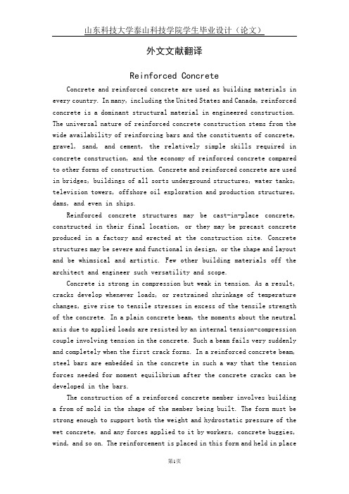
外文文献翻译Reinforced ConcreteConcrete and reinforced concrete are used as building materials in every country. In many, including the United States and Canada, reinforced concrete is a dominant structural material in engineered construction. The universal nature of reinforced concrete construction stems from the wide availability of reinforcing bars and the constituents of concrete, gravel, sand, and cement, the relatively simple skills required in concrete construction, and the economy of reinforced concrete compared to other forms of construction. Concrete and reinforced concrete are used in bridges, buildings of all sorts underground structures, water tanks, television towers, offshore oil exploration and production structures, dams, and even in ships.Reinforced concrete structures may be cast-in-place concrete, constructed in their final location, or they may be precast concrete produced in a factory and erected at the construction site. Concrete structures may be severe and functional in design, or the shape and layout and be whimsical and artistic. Few other building materials off the architect and engineer such versatility and scope.Concrete is strong in compression but weak in tension. As a result, cracks develop whenever loads, or restrained shrinkage of temperature changes, give rise to tensile stresses in excess of the tensile strength of the concrete. In a plain concrete beam, the moments about the neutral axis due to applied loads are resisted by an internal tension-compression couple involving tension in the concrete. Such a beam fails very suddenly and completely when the first crack forms. In a reinforced concrete beam, steel bars are embedded in the concrete in such a way that the tension forces needed for moment equilibrium after the concrete cracks can be developed in the bars.The construction of a reinforced concrete member involves building a from of mold in the shape of the member being built. The form must be strong enough to support both the weight and hydrostatic pressure of the wet concrete, and any forces applied to it by workers, concrete buggies, wind, and so on. The reinforcement is placed in this form and held in placeduring the concreting operation. After the concrete has hardened, the forms are removed. As the forms are removed, props of shores are installed to support the weight of the concrete until it has reached sufficient strength to support the loads by itself.The designer must proportion a concrete member for adequate strength to resist the loads and adequate stiffness to prevent excessive deflections. In beam must be proportioned so that it can be constructed. For example, the reinforcement must be detailed so that it can be assembled in the field, and since the concrete is placed in the form after the reinforcement is in place, the concrete must be able to flow around, between, and past the reinforcement to fill all parts of the form completely.The choice of whether a structure should be built of concrete, steel, masonry, or timber depends on the availability of materials and on a number of value decisions. The choice of structural system is made by the architect of engineer early in the design, based on the following considerations:1. Economy. Frequently, the foremost consideration is the overall const of the structure. This is, of course, a function of the costs of the materials and the labor necessary to erect them. Frequently, however, the overall cost is affected as much or more by the overall construction time since the contractor and owner must borrow or otherwise allocate money to carry out the construction and will not receive a return on this investment until the building is ready for occupancy. In a typical large apartment of commercial project, the cost of construction financing will be a significant fraction of the total cost. As a result, financial savings due to rapid construction may more than offset increased material costs. For this reason, any measures the designer can take to standardize the design and forming will generally pay off in reduced overall costs.In many cases the long-term economy of the structure may be more important than the first cost. As a result, maintenance and durability are important consideration.2. Suitability of material for architectural and structural function.A reinforced concrete system frequently allows the designer to combine the architectural and structural functions. Concrete has the advantage that it is placed in a plastic condition and is given the desired shapeand texture by means of the forms and the finishing techniques. This allows such elements ad flat plates or other types of slabs to serve as load-bearing elements while providing the finished floor and / or ceiling surfaces. Similarly, reinforced concrete walls can provide architecturally attractive surfaces in addition to having the ability to resist gravity, wind, or seismic loads. Finally, the choice of size of shape is governed by the designer and not by the availability of standard manufactured members.3. Fire resistance. The structure in a building must withstand the effects of a fire and remain standing while the building is evacuated and the fire is extinguished. A concrete building inherently has a 1- to 3-hour fire rating without special fireproofing or other details. Structural steel or timber buildings must be fireproofed to attain similar fire ratings.4. Low maintenance.Concrete members inherently require less maintenance than do structural steel or timber members. This is particularly true if dense, air-entrained concrete has been used for surfaces exposed to the atmosphere, and if care has been taken in the design to provide adequate drainage off and away from the structure. Special precautions must be taken for concrete exposed to salts such as deicing chemicals.5. Availability of materials. Sand, gravel, cement, and concrete mixing facilities are very widely available, and reinforcing steel can be transported to most job sites more easily than can structural steel. As a result, reinforced concrete is frequently used in remote areas.On the other hand, there are a number of factors that may cause one to select a material other than reinforced concrete. These include:1. Low tensile strength.The tensile strength concrete is much lower than its compressive strength ( about 1/10 ), and hence concrete is subject to cracking. In structural uses this is overcome by using reinforcement to carry tensile forces and limit crack widths to within acceptable values. Unless care is taken in design and construction, however, these cracks may be unsightly or may allow penetration of water. When this occurs, water or chemicals such as road deicing salts may cause deterioration or staining of the concrete. Special design details are required in such cases. In the case of water-retaining structures, special details and /of prestressing are required to prevent leakage.2. Forms and shoring. The construction of a cast-in-place structure involves three steps not encountered in the construction of steel or timber structures. These are ( a ) the construction of the forms, ( b ) the removal of these forms, and (c) propping or shoring the new concrete to support its weight until its strength is adequate. Each of these steps involves labor and / or materials, which are not necessary with other forms of construction.3. Relatively low strength per unit of weight for volume.The compressive strength of concrete is roughly 5 to 10% that of steel, while its unit density is roughly 30% that of steel. As a result, a concrete structure requires a larger volume and a greater weight of material than does a comparable steel structure. As a result, long-span structures are often built from steel.4. Time-dependent volume changes. Both concrete and steel undergo-approximately the same amount of thermal expansion and contraction. Because there is less mass of steel to be heated or cooled, and because steel is a better concrete, a steel structure is generally affected by temperature changes to a greater extent than is a concrete structure. On the other hand, concrete undergoes frying shrinkage, which, if restrained, may cause deflections or cracking. Furthermore, deflections will tend to increase with time, possibly doubling, due to creep of the concrete under sustained loads.In almost every branch of civil engineering and architecture extensive use is made of reinforced concrete for structures and foundations. Engineers and architects requires basic knowledge of reinforced concrete design throughout their professional careers. Much of this text is directly concerned with the behavior and proportioning of components that make up typical reinforced concrete structures-beams, columns, and slabs. Once the behavior of these individual elements is understood, the designer will have the background to analyze and design a wide range of complex structures, such as foundations, buildings, and bridges, composed of these elements.Since reinforced concrete is a no homogeneous material that creeps, shrinks, and cracks, its stresses cannot be accurately predicted by the traditional equations derived in a course in strength of materials forhomogeneous elastic materials. Much of reinforced concrete design in therefore empirical, i.e., design equations and design methods are based on experimental and time-proved results instead of being derived exclusively from theoretical formulations.A thorough understanding of the behavior of reinforced concrete will allow the designer to convert an otherwise brittle material into tough ductile structural elements and thereby take advantage of concrete’s desirable characteristics, its high compressive strength, its fire resistance, and its durability.Concrete, a stone like material, is made by mixing cement, water, fine aggregate ( often sand ), coarse aggregate, and frequently other additives ( that modify properties ) into a workable mixture. In its unhardened or plastic state, concrete can be placed in forms to produce a large variety of structural elements. Although the hardened concrete by itself, i.e., without any reinforcement, is strong in compression, it lacks tensile strength and therefore cracks easily. Because unreinforced concrete is brittle, it cannot undergo large deformations under load and fails suddenly-without warning. The addition fo steel reinforcement to the concrete reduces the negative effects of its two principal inherent weaknesses, its susceptibility to cracking and its brittleness. When the reinforcement is strongly bonded to the concrete, a strong, stiff, and ductile construction material is produced. This material, called reinforced concrete, is used extensively to construct foundations, structural frames, storage takes, shell roofs, highways, walls, dams, canals, and innumerable other structures and building products. Two other characteristics of concrete that are present even when concrete is reinforced are shrinkage and creep, but the negative effects of these properties can be mitigated by careful design.A code is a set technical specifications and standards that control important details of design and construction. The purpose of codes it produce structures so that the public will be protected from poor of inadequate and construction.Two types f coeds exist. One type, called a structural code, is originated and controlled by specialists who are concerned with the proper use of a specific material or who are involved with the safe design of a particular class of structures.The second type of code, called a building code, is established to cover construction in a given region, often a city or a state. The objective of a building code is also to protect the public by accounting for the influence of the local environmental conditions on construction. For example, local authorities may specify additional provisions to account for such regional conditions as earthquake, heavy snow, or tornados. National structural codes genrally are incorporated into local building codes.The American Concrete Institute ( ACI ) Building Code covering the design of reinforced concrete buildings. It contains provisions covering all aspects of reinforced concrete manufacture, design, and construction. It includes specifications on quality of materials, details on mixing and placing concrete, design assumptions for the analysis of continuous structures, and equations for proportioning members for design forces.All structures must be proportioned so they will not fail or deform excessively under any possible condition of service. Therefore it is important that an engineer use great care in anticipating all the probable loads to which a structure will be subjected during its lifetime.Although the design of most members is controlled typically by dead and live load acting simultaneously, consideration must also be given to the forces produced by wind, impact, shrinkage, temperature change, creep and support settlements, earthquake, and so forth.The load associated with the weight of the structure itself and its permanent components is called the dead load. The dead load of concrete members, which is substantial, should never be neglected in design computations. The exact magnitude of the dead load is not known accurately until members have been sized. Since some figure for the dead load must be used in computations to size the members, its magnitude must be estimated at first. After a structure has been analyzed, the members sized, and architectural details completed, the dead load can be computed more accurately. If the computed dead load is approximately equal to the initial estimate of its value ( or slightly less ), the design is complete, but if a significant difference exists between the computed and estimated values of dead weight, the computations should be revised using an improved value of dead load. An accurate estimate of dead load is particularly important when spans are long, say over 75 ft ( 22.9 m ),because dead load constitutes a major portion of the design load.Live loads associated with building use are specific items of equipment and occupants in a certain area of a building, building codes specify values of uniform live for which members are to be designed.After the structure has been sized for vertical load, it is checked for wind in combination with dead and live load as specified in the code. Wind loads do not usually control the size of members in building less than 16 to 18 stories, but for tall buildings wind loads become significant and cause large forces to develop in the structures. Under these conditions economy can be achieved only by selecting a structural system that is able to transfer horizontal loads into the ground efficiently.钢筋混凝土在每一个国家,混凝土及钢筋混凝土都被用来作为建筑材料。
土木工程外文翻译—高层建筑结构的发展
Development of Structural Forms For Tall Buildings The first steps towards the modern multistory building appear to have been taken in the Bronge Age, with the appearance of the emergence of proper cities. Even today there appears to be an instrinc relationship between the tall building, and the city. Multistory buildings were considered a characteristic of ancient Rome, and four and five-story wooden tenement buildings were common. Those built after the great fire of Nero used the new burnt brick and concrete materials in the form of arch and barrel vault structures, which replaced the earlier post and lintel construction.Throughout the following centuries, the two basic materials used in building construction were timber and masonry, although the former lacked the strength required for buildings of more than about 16m in height, and always presented a fire hazard. The latter had the advantages of high compressive strength and fire resistance, but suffered from its high weight, which tended to overload the lower supports. The limits of this form of construction became apparent in 1891 in the16-story Monadnock Building in Chicago which required the lower walls to be over 2m thick, and was the last tall building in the city for which load-bearing masonry walls were employed.The socio-econormic problems which followed the industrialization of the 19th century, allied to the insatiable demand for space in the US cities, gave a big impetus to tall building construction. However, the growth could not have been sustained without two major technical innovations during the middle of that century, namely, the development of new higher strength and structurally more efficient materials, wrought iron and subsequently steel, and the introduction of the elevator to facilitate vertical transportation.The new material allowed the development of lightweight framed or skeletal structures, permitting greater heights and more and larger openings in the building. The forerunner of the steel frame which appeared in Chicago around 1890 may well have been a seven-story iron-framed Manchester cotton mill, built in 1801,in which the contemporary I-beam shape appears to have been used for the first time. The Crystal Palace, built for the London International Exhibition of 1851, used acompletely autonomous iron frame, with columns of cast iron and beams of cast or wrought iron. One of the notable features of this design was the large-scale approach towards mass-production techniques to facilitate fabrication and erection.Although the first elevator appeared in 1851, in a New York hotel, its potential in high-rise building was apparently not realized until its incorporation in the Equitable Life Insurance Company Building in New York in 1870. For the first time, this made the upper stories as attractive a renting proposition as the lower ones, and in so doing made the taller-than-average structure financially viable.Improved steel design methods and construction techniques allowedsteel-framed structure to grow steadily upwards, although progress slowed down during the period of the First World War. In 1909, the 50-story Metropolitan Tower Building. This golden age of American skyscraper construction culminated in 1931 in its crowning glory, the Empire State Building. Its 102 stories rose to a height of 381m which has now increased to 449m with the addition of a TV aerial. The building used 57000t (US) of structural steel, nearly 53500m of concrete, and was designed and built in the record time of 17 months.Although reinforced concrete construction began to be adopted seriously around the turn of the century, it dose not appear to have been used properly for multistory buildings until after the end of the First World War. The inherent advantages of the composite material were not at that time fully appreciated, and the early systems were developed purely as imitations of steel structures. An early landmark was the 16-story Ingalls Building in Cincinnatti, Ohio, (1903), which was not superseded until 1915 when the 19-story Medical Arts Building in Dallas was hailed as the word’s tallest reinforced concrete building. Thereafter, progress was slow and intermittent, and when the Empire State Building was completed, the Exchange Building in Seattle had attained a height of only 23 stories.The economic depression of the 1930s put an end to the great skyscraper era, and it was not until some years after the end of the Second World War that the construction of high-rise building recommend, bringing with it new structural and architectural solution. However, modern developments have produced new structural layouts, improved material qualities, and better design and construction techniques rather than significant increases in height.Design philosophies altered during the period of recession and war. The earliertall buildings were characterized by having heavy structural elements and being very stiff due to the high in-plane rigidities of the interior partitions and façade cladding with low areas of fenestrastion. However, modern office blocks tend to be characterized by light demountable partitions to aloe planning flexibility of occupancy, exterior glass curtain walls, and lighter sections as a result ofhigh-strength concrete and steel material, whilst non-load-bearing infills have give way to load-bearing walls which simultaneously divide and enclose space. As a result, much of the hidden reserve of the earlier buildings has disappeared, and the basic structure must now provide both the required strength and stiffness against vertical and lateral loads. Consequently, the last there decades have seen major changes in structural framing systems for tall building.The building frame was traditionally designed to resist the gravitational loads which are always present and form the reason for its very existence. These loads derive from the self-weight of the vertical and horizontal structural components, including the cladding, and the superimposed floor loadings. There will give rise to necessary minimum cross-sectional areas, based on allowable stress levels, for the vertical column and wall elements, in the design.In the past three decades, therefore, designers have sought to evolve structural systems which will reduce as far as possible the cost and weight of materials, while simultaneously fulfilling the primary building function. A suitable arrangement of the vertical column and wall elements, allied to the horizontal floor system, is required which will provide an economic method of resisting lateral forces and minimizing the additional height premium.Although the provision of load paths for gravitational forces is limited, there is considerable scope for organizing the structural system to resist lateral forces as efficiently as possible. This may be achieved by the judicious disposition of the vertical elements and their interconnection by horizontal structural components in order to resist moment by axial forces rather than bending moments in these vertical elements.In general, different structural systems have evolved for residential and office buildings have been constructed in which the two categories have been mixed, in a deliberate attempt to revitalize moribund city center areas.The basic functional requirement of a residential building is the provision ofdiscrete dwelling units for groups of individuals. These have common requirements of living, sleeping, cooking and toilet areas, which must be separated by partitions which offer fire and acoustic insulation between dwelling.Framed structures may be usefully employed for residential buildings, since the presence of permanent partitions allows the column layout to the correspond to the architectural plan. However, these depend on the rigidity of the joints for their resistance to lateral forces, and tend to become uneconomic at heights above 20-25 stories, depending on the overall dimensions, when wind forces begin to control the design, and it becomes increasingly difficult to meet stiffness requirements. Since their introduction in the late 1940s, shear walls, acting either independence or in the form of core assemblies, have been used extensively as additional stiffening elements for traditional frame structures.In order to provide adequate fire and acoustic insulation between dwellings, infill panels of brickwork or blockwork are introduced into the frames. Although techniques exist for assessing the influence of these infill panels on the strength and stiffness of the frame, they are generally assumed to be non-load-bearing, in view of the designer’s fear that they may be either removed or perforated for a change of function at some future date, as well as the difficulty of achieving a tight fit between an infill panel and the surrounding frame. Consequently, later trends were to utilize the walls which are required for space division in a structural context, and omit the relatively heavy infills which could not be employed in a load resisting capacity. This has led to the development of the shear wall building, in which structural walls are used to divide and enclose space, while simultaneously resisting both vertical and horizontal loads. These walls are generally of precast large panel or reinforced concrete in-situ construction, but concrete blockwork and brickwork have also been employed, allied to precast floor slab construction. Since the functional plan requires a large number of division walls between dwellings, it is frequently found that the minimum thickness required for fire and acoustic insulation will be adequate for structural requirements also.Functional requirements for this form of building have given rise to the slab block of cross-wall construction, in which horizontal movement of occupants is achieved by long corridors running along the length of the building, with apartments positioned on either side, or to point blocks in which apartments are grouped around the area ofvertical transportation, lifts and stairwells. In each case, the basic structure consists of orthogonal systems of shear walls, connected by floor slabs and perhaps lintel beams spanning across door, window or corridor openings, to form a stiff structure. Structural cores, which consist of assemblies of walls along their vertical edges to form open or partially closed box sections enclosing lift shafts and stair wells act as additional strong points in such buildings, and can play a major role in resisting lateral forces.In a design, the shear walls must be sufficiently stiff to meet the imposed deflection criterion, and in addition, should be so arranged that tensile stresses caused by wind forces are less than the compressive stresses produced by the weight of the building. A careful arrangement of walls can improve structural efficiency which consists of a series of cross-walls and two flank walls running across the width of the building. As a reasonable approximation, each wall will carry the vertical loads associated with the surrounding tributary area shown hatched in the figure, so that the compressive stresses in the cross walls will be roughly twice those in the flank walls, if they are of the same thickness, However, if all walls deflect equally under the action of the wind forces, as a result of the high in-plane rigidity of the floor slabs, the bending moment and associated stresses in each wall will be proportional respectively to its moment of inertia and section modulus. Consequently, the maximum tensile stresses in the flank walls will be roughly four times those in the cross-walls. The flank walls may then be subjected to unacceptable tensile stresses. A more efficient structure could be achieved by splitting each flank wall into two units, perhaps by forming an architectural feature by having them out of alignment. The flank walls would then be subjected to roughly the same wind moments as the cross-walls, and the tensile wind stresses reduced by a factor of more than four.Shear wall structures are well suited for resisting seismic loadings, and have performed well in recent disasters. They tend to become economical as soon as lateral forces affect the design and proportioning of flat plate or framed systems. However, they do possess the disadvantage of an inherent lack of flexibility for future modifications, while discontinuities are frequently required at the critical ground level area to provide a different architectural function on the ground floor, and special detailing becomes necessary.A relative recent innovation which is particularly suitable for residential blocks isthe staggered wall-beam system. The structure consists of a series of parallel bents, each comprising columns with perforated story-height walls between them, in alternate bays. Each wall panel acts in conjunction with, and supports, the slab above and below to form a composite I-beam. By this device, large clear areas are created on each floor, yet the floor slabs span only half the distance between adjacent wall beams, from the bottom of one to the top of the next. The wind shears are transmitted through the floor slabs from the wall beams on one story to shoes on the next. Similar systems are possible with staggered trusses rather than stagtered walls.The essential functional requirement of an office building is the provision of areas unobstructed as possible by walls or columns to allow each occupant to design the partitioning and space enclosure most suitable for his particular business organization. The partition layout will generally alter when tenants change, and this necessitates flexibility in the distribution of the various services to any particular floor. As a result, services tend to be carried vertically within one or more service cores, and a distribution network run beneath the structural floor slab to the entire floor area.By judicious planning of the column layout to maximize the open floor areas, shear wall-frame interactive structures may also be employed for office blocks, although the presence of the columns may make it difficult to achieve the desired planning flexibility.Possibly the simplest method of creating open floor areas is to use a central concrete shear core, which carries all essential services and which is designed to resist all lateral forces. The floor system spans between the central core and the exteriorfaçade columns, and a large unobstructed floor area is created between the two vertical components. The exterior columns can be designed to be effectivelypin-connected at each floor level, so that they transmit vertical forces only, in conjunction with the interior core. These exterior columns are frequently precast to form a sculptured façade. Another possibility is to provide a core at each end, especially if the building is slender. However, in order to support the floor slabs in the interior, it is then necessary to provide a spine beam running between the cores, which will require additional supporting interior columns. If the floor spans are long, it may become economic to introduce additional columns in the interior to reduce the span of the slabs.In some situations, a different architectural arrangement is desired at groundlevel, which precludes the columns being taken right down to ground level. In that case, heavy cantilevers are required to collect the column loads from the levels above and transmit then to the central core.An alternative approach is to introduce a roof truss in either prestressed concrete or steel construction, at the top of the core. The floor slabs may then be supported between the core and a system of steel hangers suspended from the roof truss. The system has the architectural advantage of lightness of façade, and can simplify construction on a congested city site. The core may be slipformed, and the floor slabs cast on site and simply hoisted into position. However, there is the inherent structural disadvantage that the core is subjected to the entire weight of the building , compressive forces are high at roof level, and settlement may pose problems. Intermediate level trusses will assist in carrying the external tie forces and reduce the extensions of the hangers.A further increase in lateral stiffness can be achieved if the central core or shear wall system is tied to the exterior columns by deep (usually story height) flexural members or trusses at the top and possibly at other intermediate levels. The effect of these connections is to create an overall framed system, which mobilizes the axial stiffness of the exterior columns to resist wind forces. The objective is to cause the structure to act more as a vertical cantilever beam, and so resist the wind by axial forces in, rather than by bending of. The larger lever arm involved ensures that large moments of resistance may be produced by relatively low column forces.The first reinforced concrete building to utilize this concept was the 51-story Place Victoria Building in Montreal (1964) , in which an X-shaped core is linked at four levels by story-high graders to the massive corner columns.As building become taller, the use of a core on its own to resist lateral forces will lead to unusually large cores, occupying too large a ratio of a given floor area, and leading to uneconomic solutions. The efficiency can be increased substantially if the outer façade is replaced by a rigidly-jointed framework, which can be used to resist lateral as well as vertical forces. The outer shell then acts effectively as a closedbox-like structure, whose faces are formed of rigidly-jointed frame panels, or as a highly perforated tube, whose cross-sectional shape is maintained by the floor slabs acting as horizontal diaphragms.A combination of the framed-tube concept with the shear wall-frame interactionconcept yields the structural from termed the tube-in tube system, in which an exterior closely spaced column system is constrained by the floor slabs to act in collaboration with a very stiff shear core enclosing the central service area. The first design application of this form of shear wall-frame interactive behaviour appears to have been in the 38-story Brunswick Building in Chicago, completed in 1962. In this case, the lateral forces are resisted by both the interior core and outer framed tube, in proportion to their stiffnesses. The large lever arm involved between opposite normal faces of the exterior tube give rise to an efficient moment-resisting structure, akin to an ordinary tubular structural component.While the system is very useful in the creation of flexible spaces in office buildings, it is less suitable for very tall apartment buildings. An alternative solution using the framed-tube concept was devised first for the 43-story De Witt Chestnut Apartment Building in Chicago in 1965. In this case, the exterior columns were closely spaced at 1.68m centres and, when rigidly connected to 600mm deep spandrel beams, gave rise to a relatively stiff exterior perforated tube which was designed to resist all wind forces. A system of interior columns at approximately 6m spacing was provided to support the flat plate type of floor construction. The closely spaced exterior columns in this form of construction allow simpler methods of fixing the window glazing directly to the columns themselves.The closely-spaced columns in a framed tube may pose problems in gaining across to the building at ground level, and some structural rearrangement may be necessary in that region. Several columns may be run into one at regular intervals, as in the World Trade Center, or a deep girder may be provided at first-floor level to transfer column forces to more widely spaced first-floor columns.The pure framed tube has the disadvantage that under bending action, a considerable degree of shear lag occurs in the faces normal to the wind, as a result of the flexibility of the spandrel beams. This has the effect of increasing the stresses in the corner columns, and of reducing those in the inner columns of the normal panels, and results in a loss of efficiency in the desired pure tubular action of the structure. Warping of the floor slabs, and consequently deformations of interior partitions and secondary structure will occur, which may become of importance in design.One technique which has been employed to help overcome this problem is to add substantial diagonal bracing members in the planes of the exterior frames. Theexterior columns may then be more widely spaced, and the diagonals, aligned at some 45°to the vertical, serve to tie together the exterior columns and spandrel beams to form façade trusses. Consequently, a very rigid cantilever tube is produced. The diagonals, however, pose their own special problems in the design of the curtain wall system. Although the technique has been used only in steel construction so far, there appears to be no intrinsic reason why it should not be a feasible solution for tall concrete structures.For very tall buildings, the shear lag effect may be greatly reduced by adding additional interior web panels across the entire width of the building in each direction to form a modular tube or bundled-tube system. The additional stiffening of the structure produced by the interior webs increase the local stress levels at the exterior frame junction and thereby reduces substantially the nonuniformity of column forces caused by shear lag. The structure may be regarded as a set of modular tubes which are interconnected with common panels to form a perforated multi-cell tube, in which the frames in the wind direction resist the wind shears. The system is such that modules can be omitted at different heights to reduce the cross-section and still maintain the structural integrity. Any torsion arising from the resulting unsymmetry is readily resisted by the closed-sectional form of the modules.The best known example of this form of construction is the 109-story, 442m high, Sears Tower in Chicago, the world’s tallest building. Completed in 1974, the basic cross-sectional shape consists of nine 22.86m square modular tubes, for an overall floor area 68.58m square, which continues up to the 50th floor. Step backs, produced by a termination of one or more of the modular tubes, then occur at floor 50, 66 and 90, creating a variety of floor configurations.An alternative possibility, yielding the same general form of structural behaviour, is to use shear walls to form the interior webs of the framed tube and create an alternative form of multi-cellular construction. This approach has been adopted for the 74-story, 262m high Water Tower Place Building, Chicago (1976), the world’s tallest concrete building. The 64-story tower which rises from a 12-story base is a slender tube of cross–sectional dimensions 67×29m which is bisected by an internal transverse perforated shear wall to form a two-cell structure. The building is amulti-purpose one and encompasses an hotel and apartments in addition to office space.译文:高层建筑结构的发展建筑的出现应该追溯到青铜器时代,伴随着真正的城市的出现,房子也出现了两层的。
- 1、下载文档前请自行甄别文档内容的完整性,平台不提供额外的编辑、内容补充、找答案等附加服务。
- 2、"仅部分预览"的文档,不可在线预览部分如存在完整性等问题,可反馈申请退款(可完整预览的文档不适用该条件!)。
- 3、如文档侵犯您的权益,请联系客服反馈,我们会尽快为您处理(人工客服工作时间:9:00-18:30)。
中英文资料翻译1外文资料The Tall Office Building Artistically ConsideredThe architects of this land and generation are now brought face to face with something new under the sun namely, that evolution and integration of social conditions, that special grouping of them, that results in a demand for the erection of tall office buildings.It is not my purpose to discuss the social conditions; I accept them as the fact, and say at once that the design of the tall office building must be recognized and confronted at the outset as a problem to be solved a vital problem, pressing for a true solution.Let us state the conditions in the plainest manner. Briefly, they are these: offices are necessary for the transaction of business; the invention and perfection of the high speed elevators make vertical travel, that was once tedious and painful, now easy and comfortable; development of steel manufacture has shown the way to safe, rigid, economical constructions rising to a great height; continued growth of population in the great cities, consequent congestion of centers and rise in value of ground, stimulate an increase in number of stories; these successfully piled one upon another, react on ground values and so on, byaction and reaction, interaction and inter reaction. Thus has come about that form of lofty construction called the "modern office building". It has come in answer to a call, for in it a new grouping of social conditions has found a habitation and a name.Up to this point all in evidence is materialistic, an exhibition of force, of resolution, of brains in the keen sense of the word. It is the joint product of the speculator, the engineer, the builder.Problem: How shall we impart to this sterile pile, this crude, harsh, brutal agglomeration, this stark, staring exclamation of eternal strife, the graciousness of these higher forms of sensibility and culture that rest on the lower and fiercer passions? How shall we proclaim from the dizzy height of this strange, weird, modern housetop the peaceful evangel of sentiment, of beauty, the cult of a higher life?This is the problem; and we must seek the solution of it in a process analogous to its own evolution indeed, a continuation of it namely, by proceeding step by step from general to special aspects, from coarser to finer considerations.It is my belief that it is of the very essence of every problem that is contains and suggests its own solution. This I believe to be natural law. Let us examine, then, carefully the elements, let us search out this contained suggestion, this essence of the problem.The practical conditions are, broadly speaking, these:Wanted 1st, a story below ground, containing boiler, engines of various sorts, etc. in short, the plant for power, heating, lighting, etc. 2nd, a ground floor, so called, devoted to stores, banks, or other establishments requiring large area, ample spacing, ample light, and great freedom of access, 3rd, a second story readily accessible by stairways this space usually in large subdivisions, with corresponding liberality in structural spacing and expanse of glass and breadth of external openings, 4th, above this an indefinite number of stories of offices piled tier upon tier, one tier just like another tier, one office just like all the other offices an office being similar to a cell in honey comb, merely a compartment, nothing more, 5th, and last, at the top of this pile is placed a space or story that, as related to the life and usefulness of the structure, is purely physiological in its nature namely, the attic. In this the circulatory system completes itself and makes it grand turn, ascending and descending. The space is filled with tanks, pipes, valves, sheaves, and mechanical etcetera that supplement and complement the force originating plant hidden below ground in the cellar. Finally, or at the beginning rather, there must be on the ground floor a main aperture or entrance common to all the occupants or patrons of the building.This tabulation is, in the main, characteristic of every tall office building in the country. As to the necessary arrangements for light courts, these are not germane to the problem, and as will become soon evident, I trust need not be considered here. These things, and such others as the arrangement of elevators, for example, have to do strictly with the economics of the building, and I assumethem to have been fully considered and disposed of to the satisfaction of purely utilitarian and pecuniary demands. Only in rare instances does the plan or floor arrangement of the tall office building take on an aesthetic value, and thus usually when the lighting court is external or becomes an internal feature of great importance.As I am here seeking not for an individual or special solution, but for a true normal type, the attention must be confined to those conditions that, in the main, are constant in all tall office buildings, and every mere incidental and accidental variation eliminated from the consideration, as harmful to the clearness of the main inquiry.The practical horizontal and vertical division or office unit is naturally based on a room of comfortable area and height, and the size of this standard office room as naturally predetermines the standard structural unit, and, approximately, the size of window openings. In turn, these purely arbitrary units of structure form in an equally natural way the true basis of the artistic development of the exterior. Of course the structural spacings and openings in the first or mercantile story are required to be the largest of all; those in the second or quasi mercantile story are of a some what similar nature. The spacings and openings in the attic are of no importance whatsoever the windows have no actual value, for light may be taken from the top, and no recognition of a cellular division is necessary in the structural spacing.Hence it follow inevitably, and in the simplest possible way, that if wefollow our natural instincts without thought of books, rules, precedents, or any such educational impediments to a spontaneous and "sensible" result, we will in the following manner design the exterior of our tall office building to wit: Beginning with the first story, we give this a min entrance that attracts the eye to it location, and the remainder of the story we treat in a more or less liberal, expansive, sumptuous way a way based exactly on the practical necessities, but expressed with a sentiment of largeness and freedom. The second story we treat in a similar way, but usually with milder pretension. Above this, throughout the indefinite number of typical office tiers, we take our cue from the individual cell, which requires a window with its separating pier, its still and lintel, and we, without more ado, make them look all alike because they are all alike. This brings us to the attic, which having no division into office cells, and no special requirement for lighting, gives us the power to show by means of its broad expanse of wall, and its dominating weight and character, that which is the fact namely, that the series of office tiers has come definitely to an end.This may perhaps seem a bald result and a heartless, pessimistic way of stating it, but even so we certainly have advanced a most characteristic stage beyond the imagined sinister building of the speculator engineer builder combination. For the hand of the architect is now definitely felt in the decisive position at once taken, and the suggestion of a thoroughly sound, logical, coherent expression of the conditions is becoming apparent.When I say the hand of the architect, I do not mean necessarily theaccomplished and trained architect. I mean only a man with a strong, natural liking for buildings, and a disposition to shape them in what seems to his unaffected nature a direct and simple way. He will probably tread an innocent path from his problem to its solution, and therein he will show an enviable gift of logic. If we have some gift for form in detail, some feeling for form purely and simply as form, some love for that, his result in addition to it simple straightforward naturalness and completeness in general statement, will have something of temperament and interest.However, thus far the results are only partial and tentative at best relatively true, they are but superficial. We are doubtless right in our instinct but we must seek a fuller justification, a finer sanction, for it.I assume now that in the study of our problem we have passed through the various stages of inquiry, as follows: 1st, the social basis of the demand for tall buildings; 2nd, its literal material satisfaction; 3rd, the elevation of the question from considerations of literal planning, construction, and equipment, to the plane of elementary architecture as a direct outgrowth of sound, sensible building; 4th, the question again elevated from an elementary architecture to the beginnings of true architectural expression, through the addition of a certain quality and quantity of sentiment.But our building may have all these in a considerable degree and yet be far from that adequate solution of the problem I am attempting to define. We must now heed quality and quantity of sentiment.It demands of us, what is the chief characteristic of the tall office building? And at once we answer, it is lofty. This loftiness is to the artist nature its thrilling aspect. It is the very open organ tone in its appeal. It must be in turn the dominant chard in his expression of it, the true excitant of his imagination. It must be tall, every inch of it tall. The force and power of altitude must be in it, the glory and pride of exaltation must be in it. It must be every inch a proud and soaring thing, rising in sheer exultation that from bottom to top it is a unit without a single dissenting line that it is the new, the unexpected, the eloquent peroration of most bald, most sinister, most forbidding conditions.The man who designs in the spirit and with the sense of responsibility to the generation he lives in must be no coward, no denier, no bookworm, no dilettante. He must live of his life and for his life in the fullest, most consummate sense. He must realize at once and with the grasp of inspiration that the problem of the tall office building is one of the most stupendous, one of the most magnificent opportunities that the Lord of Nature in His beneficence has ever offered to the proud spirit of man.That this has not been perceived indeed has been flatly denied is an exhibition of human perversity that must give us pause.One more consideration. Let us now lift this question into the region of calm, philosophic observation. Let us seek a comprehensive, a final solution: let the problem indeed dissolve.Certain critics, and very thoughtful ones, have advanced the theory that thetrue prototype of the tall office building is the classical column, consisting of base, shaft and capital the molded base of the column typical of the lower stories of our building, the plain or fluted shaft suggesting the monotonous, uninterrupted series of office tiers, and the capital the completing power and luxuriance of the attic.Other theorizers, assuming a mystical symbolism as a guide, quite the many trinities in nature and art, and the beauty and conclusiveness of such trinity in unity. They aver the beauty of prime numbers, the mysticism of the number three, the beauty of all things that are in three parts to wit, the day, subdividing into morning, noon, and night; the limbs, the thorax, and the head, constituting the body. So they say, should the building be in three parts vertically, substantially as before, but for different motives.Others, of purely intellectual temperament, hold that such a design should be in the nature of a logical statement; it should have a beginning, a middle, and an ending, each clearly defined therefore again a building, as above, in three parts vertically.2中文翻译高层办公建筑艺术思考这个时代该领域的建筑师开始正视一些新的由于社会条件变革和整合以及它们特殊组合导致的对高层办公建筑的立面要求。