高层建筑设计中英文对照外文翻译文献
外文翻译 外文文献 英文文献 上海高层住宅建筑的高度及成本
原文题目:Height and Construction Costs of Residential High-Rise Buildings in Shanghai译文题目:上海高层住宅建筑的高度及成本附件1:外文资料翻译译文上海高层住宅建筑的高度及成本摘要:每平方米的建筑成本是随着建筑成本的增加而增加的,这是一个得到广泛认可的建筑经济学主题。
然而,在过去的数年中,对于有关高度和成本的相关问题,已经建立了一个经典的关系,两者之间的关系可以通过一个U形曲线表示。
本文介绍了有关上海高层住宅楼的总建筑成本和各部分的成本与高度的关系的研究。
同时也考虑了建筑物的背景与存在的共性。
本项研究是在审查香港楼宇的一些数据之前所需做的前期工作。
初步研究表明:上海和香港楼宇高度与成本的曲线变现出不同的类型。
这些差异表明,在不同地点应该有两套不同的标准。
调查结果显示,相关费用在建设高度的变化作出反应的方式上存在差异。
DOI: 10.1061/ ASCE CO.1943-7862.0000226CE数据库标题:建设成本;高度;建筑物,高层建筑,住宅;中国。
关键词:建设成本高度建筑物高度增长介绍人口基金2007年的报告显示,到2030年,世界城市人口将会达到4.9亿。
80%的人口将在发展中国家的城镇和城市。
由于世界资源的集中利用,这将给人类的生活质量带来很大的负担。
为了纾缓高密度压力,在商业和住宅结构等领域增加高层建筑是非常合理的建议,尤其是在亚洲和中东地区。
在今后的几年中,亚洲和中东将成为高层建筑的中心,特别是高度超过300米/1000英尺的战况建设。
据高层建筑与城市理事会最近的研究表明,在2020年出现的20个高层建筑里,有9个出现在亚洲,8个在中东,2个在北美,1个在欧洲(2009)。
本文所描述的研究集中在上海高层住宅楼的的高度与成本的关系,成本被认为有两种成本,总的成本和元素成本。
众所周知,上海市一个高密度的城市,算是世界上增长最快的城市之一。
建筑结构设计中英文对照外文翻译文献

中英文对照外文翻译(文档含英文原文和中文翻译)Create and comprehensive technology in the structure globaldesign of the buildingThe 21st century will be the era that many kinds of disciplines technology coexists , it will form the enormous motive force of promoting the development of building , the building is more and more important too in global design, the architect must seize the opportunity , give full play to the architect's leading role, preside over every building engineering design well. Building there is the global design concept not new of architectural design,characteristic of it for in an all-round way each element not correlated with building- there aren't external environment condition, building , technical equipment,etc. work in coordination with, and create the premium building with the comprehensive new technology to combine together.The premium building is created, must consider sustainable development , namely future requirement , in other words, how save natural resources as much as possible, how about protect the environment that the mankind depends on for existence, how construct through high-quality between architectural design and building, in order to reduce building equipment use quantity andreduce whole expenses of project.The comprehensive new technology is to give full play to the technological specialty of every discipline , create and use the new technology, and with outside space , dimension of the building , working in coordination with in an all-round way the building component, thus reduce equipment investment and operate the expenses.Each success , building of engineering construction condense collective intelligence and strength; It is intelligence and expectation that an architect pays that the building is created; The engineering design of the building is that architecture , structure , equipment speciality compose hardships and strength happenning; It is the diligent and sweat paid in design and operation , installation , management that the construction work is built up .The initial stage of the 1990s, our understanding that the concept of global design is a bit elementary , conscientious to with making some jobs in engineering design unconsciously , make some harvest. This text Hangzhou city industrial and commercial bank financial comprehensive building and Hangzhou city Bank of Communications financial building two building , group of " scientific and technological progress second prize " speak of from person who obtain emphatically, expound the fact global design - comprehensive technology that building create its , for reach global design outstanding architect in two engineering design, have served as the creator and persons who cooperate while every stage design and even building are built completely.Two projects come into operation for more than 4 years formally , run and coordinate , good wholly , reach the anticipated result, accepted and appreciated by the masses, obtain various kinds of honor .outstanding to design award , progress prize in science and technology , project quality bonus , local top ten view , best model image award ,etc., the ones that do not give to the architect and engineers without one are gratified and proud. The building is created Emphasizing the era for global design of the building, the architects' creation idea and design method should be broken through to some extent, creation inspirations is it set up in analysis , building of global design , synthesize more to burst out and at the foundation that appraise, learn and improve the integration capability exactly designed in building , possess the new knowledge system and thinking method , merge multi-disciplinary technology. We have used the new design idea in above-mentioned projects, have emphasized the globality created in building .Is it is it act as so as to explain to conceive to create two design overview and building of construction work these now.1) The financial comprehensive building of industrial and commercial bank of HangZhou,belong to the comprehensive building, with the whole construction area of 39,000 square meters, main building total height 84, 22, skirt 4 of room, some 6 storeys, 2 storeys of basements.Design overall thinking break through of our country bank building traditional design mode - seal , deep and serious , stern , form first-class function, create of multi-functional type , the style of opening , architecture integrated with the mode of the international commercial bank.The model of the building is free and easy, opened, physique was made up by the hyperboloid, the main building presented " the curved surface surrounded southwards ", skirt room presents " the curved surface surrounded northwards ", the two surround but become intension of " gathering the treasure ".Building flourishing upwards, elevation is it adopt large area solid granite wall to design, the belt aluminium alloy curtain wall of the large area and some glass curtain walls, and interweave the three into powerful and vigorous whole , chase through model and entity wall layer bring together , form concise , tall and straight , upward tendency of working up successively, have distinct and unique distinctions.Building level and indoor space are designed into a multi-functional type and style of opening, opening, negotiate , the official working , meeting , receiving , be healthy and blissful , visit combining together. Spacious and bright two storeys open in the hall unifiedly in the Italian marble pale yellow tone , in addition, the escalator , fountain , light set off, make the space seem very magnificent , graceful and sincere. Intelligent computer network center, getting open and intelligent to handle official business space and all related house distribute in all floor reasonably. Top floor round visit layer, lift all of Room visit layer , can have a panoramic view of the scenery of the West Lake , fully enjoy the warmth of the nature. 2) The financial building of Bank of Communications of Hangzhou, belong to the purely financial office block, with the whole construction area of 19,000 square meters, the total height of the building is 39.9 meters, 13 storeys on the ground, the 2nd Floor. Live in building degree high than it around location , designer have unique architectural appearance of style architectural design this specially, its elevation is designed into a new classical form , the building base adopts the rough granite, show rich capability , top is it burn granite and verticality bar and some form aluminum windows make up as the veneer to adopt, represent the building noble and refined , serious personality of the bank.While creating in above-mentioned two items, besides portraying the shape of the building and indoor space and outside environment minister and blending meticulously, in order to achieve the outstanding purpose of global design of the building , the architect , still according to the region and project characteristic, put forward the following requirement to every speciality:(1) Control the total height of the building strictly;(2) It favorable to the intelligent comfortable height of clearances to create; (3) Meet thefloor area of owner's demand;(4)Protect the environment , save the energy , reduce and make the investment;(5) Design meticulously, use and popularize the new technology; (6)Cooperate closely in every speciality, optimization design.Comprehensive technologyThe building should have strong vitality, there must be sustainable development space, there should be abundant intension and comprehensive new technology. Among above-mentioned construction work , have popularized and used the intelligent technology of the building , has not glued and formed the flat roof beam of prestressing force - dull and stereotyped structure technology and flat roof beam structure technology, baseplate temperature mix hole , technology of muscle and base of basement enclose new technology of protecting, computer control STL ice hold cold air conditioner technology, compounding type keeps warm and insulates against heat the technology of the wall , such new technologies as the sectional electricity distribution room ,etc., give architecture global design to add the new vitality of note undoubtedly.1, the intelligent technology of the buildingIn initial stage of the 1990s, the intelligent building was introduced from foreign countries to China only as a kind of concept , computer network standard is it soon , make information communication skeleton of intelligent building to pursue in the world- comprehensive wiring system becomes a kind of trend because of 10BASE-T. In order to make the bank building adapt to the development of the times, the designer does one's utmost to recommend and design the comprehensive wiring system with the leading eyes , this may well be termed the first modernized building which adopted this technical design at that time.(1) Comprehensive wiring system one communication transmission network, it make between speech and data communication apparatus , exchange equipment and other administrative systems link to each other, make the equipment and outside communication network link to each other too. It include external telecommunication connection piece and inside information speech all cable and relevant wiring position of data terminal of workspace of network. The comprehensive wiring system adopts the products of American AT&T Corp.. Connected up the subsystem among the subsystem , management subsystem , arterial subsystem and equipment to make up by workspace subsystem , level.(2) Automated systems of security personnel The monitoring systems of security personnel of the building divide into the public place and control and control two pieces of systemequipment with the national treasury special-purposly synthetically.The special-purpose monitoring systems of security personnel of national treasury are in the national treasury , manage the storehouse on behalf of another , transporting the paper money garage to control strictly, the track record that personnel come in and go out, have and shake the warning sensor to every wall of national treasury , the camera, infrared microwave detector in every relevant rooms, set up the automation of controlling to control.In order to realize building intellectuality, the architect has finished complete indoor environment design, has created the comfortable , high-efficient working environment , having opened up the room internal and external recreation space not of uniform size, namely the green one hits the front yard and roofing, have offered the world had a rest and regulated to people working before automation is equipped all day , hang a design adopt the special building to construct the node in concrete ground , wall at the same time.2, has not glued and formed the flat roof beam of prestressing force- dull and stereotyped structure technology and flat roof beam structure technologyIn order to meet the requirement with high assurance that the architect puts forward , try to reduce the height of structure component in structure speciality, did not glue and form the flat roof beam of prestressing force concrete - dull and stereotyped structure technology and flat roof beam structure technology after adopting.(1) Adopt prestressing force concrete roof beam board structure save than ordinary roof beam board concrete consumption 15%, steel consumption saves 27%, the roof beam reduces 300mm high.(2) Adopt flat roof beam structure save concrete about 10% consumption than ordinary roof beam board, steel consumption saves 6.6%, the roof beam reduces 200mm high.Under building total situation that height does not change , adopt above-mentioned structure can make the whole building increase floor area of a layer , have good economic benefits and social benefit.3, the temperature of the baseplate matches muscle technologyIn basement design , is it is it is it after calculating , take the perimeter to keep the construction technology measure warm to split to resist to go on to baseplate, arrange temperature stress reinforcing bar the middle cancelling , dispose 2 row receives the strength reinforcing bar up and down only, this has not only save the fabrication cost of the project but also met the basement baseplate impervious and resisting the requirement that splits.4, the foundation of the basement encloses and protects the new technology of design and operationAdopt two technological measures in enclosing and protecting a design:(1) Cantilever is it is it hole strength is it adopt form strengthen and mix muscle technology to design to protect to enclose, save the steel and invite 60t, it invests about 280,000 to save.(2) Is it is it protect of of elevation and keep roof beam technology to enclose , is it protect long to reduce 1.5m to enclose all to reduce, keep roof beam mark level on natural ground 1.5m , is it is it protect of lateral pressure receive strength some height to enclose to change, saving 137.9 cubic meters of concrete, steel 16.08t, reduces and invests 304,000 yuan directly through calculating.5, ice hold cold air conditioner technologyIce hold cold air conditioner technology belong to new technology still in our country , it heavy advantage that the electricity moves the peak and operates the expenses sparingly most. In design, is it ice mode adopt some (weight ) hold mode of icing , is it ice refrigeration to be plane utilization ratio high to hold partly to hold, hold cold capacity little , refrigeration plane capacity 30%-45% little than routine air conditioner equipment, one economic effective operational mode.Hold the implementation of the technology of the cold air conditioner in order to cooperate with the ice , has used intelligent technology, having adopted the computer to control in holding and icing the air conditioner system, the main task has five following respects:(1) According to the demand for user's cold load , according to the characteristic of the structure of the electric rate , set up the ice and hold the best operation way of the cold system automatically, reduce the operation expenses of the whole system;(2) Fully utilize and hold the capacity of the cold device, should try one's best to use up all the cold quantity held basically on the same day;(3) Automatic operation state of detection system, ensure ice hold cold system capital equipment normal , safe operation;(4) Automatic record parameter that system operate, display system operate flow chart and type systematic operation parameter report form;(5) Predict future cooling load, confirm the future optimization operation scheme.Ice hold cold air conditioner system test run for some time, indicate control system to be steady , reliable , easy to operate, the system operates the energy-conserving result remarkably.6, the compounding type keeps in the wall warm and insulates against heat To the area of Hangzhou , want heating , climate characteristic of lowering the temperature in summer in winter, is it protect building this structural design person who compound is it insulate against heat the wall to keep warm to enclose specially, namely: Fit up , keep warm , insulate against heat the three not to equal to the body , realize building energy-conservation better.Person who compound is it insulate against heat wall to combine elevation model characteristic , design aluminium board elevation renovation material to keep warm, its structure is: Fill out and build hollow brick in the frame structure, do to hang the American Fluorine carbon coating inferior mere aluminium board outside the hollow brick wall.Aluminium board spoke hot to have high-efficient adiabatic performance to the sun, under the same hot function of solar radiation, because the nature , color of the surface material are different from coarse degree, whether can absorb heat have great difference very , between surface and solar radiation hot absorption system (α ) and material radiation system (Cλ ) is it say to come beyond the difference this. Adopt α and Cλ value little surface material have remarkable result , board α、Cλ value little aluminium have, its α =0.26, Cλ =0.4, light gray face brick α =0.56, Cλ =4.3.Aluminium board for is it hang with having layer under air by hollow brick to do, because aluminium board is it have better radiation transfer to hot terms to put in layer among the atmosphere and air, this structure is playing high-efficient adiabatic function on indoor heating too in winter, so, no matter or can well realize building energy-conservation in winter in summer.7, popularize the technology of sectional electricity distribution roomConsider one layer paves Taxi " gold " value , the total distribution of the building locates the east, set up voltage transformer and low-voltage distribution in the same room in first try in the design, make up sectional electricity distribution room , save transformer substation area greatly , adopt layer assign up and down, mixing the switchyard system entirely after building up and putting into operation, the function is clear , the overall arrangement compactness is rational , the systematic dispatcher is flexible . The technology have to go to to use and already become the model extensively of the design afterwards.ConclusionThe whole mode designed of the building synthetically can raise the adaptability of the building , it will be the inevitable trend , environmental consciousness and awareness of saving energy especially after strengthening are even more important. Developing with the economy , science and technology constantly in our country, more advanced technology and scientific and technical result will be applied to the building , believe firmly that in the near future , more outstanding building global design will appear on the building stage of our country. We will be summarizing, progressing constantly constantly, this is that history gives the great responsibility of architect and engineer.译文:建筑结构整体设计-建筑创作和综合技术21世纪将是多种学科技术并存的时代,它必将形成推动建筑发展的巨大动力,建筑结构整体设计也就越来越重要,建筑师必须把握时机,充分发挥建筑师的主导作用,主持好各项建筑工程设计。
高层建筑展望及建筑结构外文文献翻译、中英文翻译、外文翻译
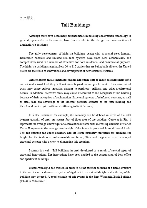
The future of the tall building and structure of buildings Zoning effects on the density of tall buildings and solar design may raise ethical challenge. A combined project of old and new buildings may bring back human scale to our cities. Owners and conceptual designers will be challenged in the 1980s to produce economically sound, people-oriented buildings.In 1980 the Level House, designed by Skidmore, Owings and Merril1 (SOM) received the 25-year award from the American Institute of Architects “in recogn ition of architectural design of enduring significance”. This award is given once a year for a building between 25and 35 years old .Lewis Mumford described the Lever House as “the first office building in which modern materials, modern construction, modern functions have been combined with a modern plan”. At the time, this daring concept could only be achieved by visionary men like Gordon Bunshaft, the designer , and Charles Luckman , the owner and then-president of Lever Brothers . The project also include d a few “first” : (1) it was the first sealed glass tower ever built ; (2) it was the first office building designed by SOM ;and (3) it was the first office building on Park Avenue to omit retail space on the first floor. Today, after hundreds of look-alike and variations on the grid design, we have reached what may be the epitome of tall building design: the nondescript building. Except for a few recently completed buildings that seem to be people-oriented in their lower floors, most tall buildings seem to be arepletion of the dull, graph-paper-like monoliths in many of our cities. Can this be the end of the design-line for tall buildings? Probably cannot. There are definite signs that are most encouraging. Architects and owners have recently begun to discuss the design problem publicly. Perhaps we are at the threshold of a new era. The 1980s may bring forth some new visionaries like Bunshaft and Luckman. If so, what kinds of restrictions or challenges do they face?Zoning Indications are strong that cities may restrict the density of tall buildings, that is, reduce the number of tall buildings per square mile. In 1980 the termgrid-lock was used for the first time publicly in New York City. It caused a terror-like sensation in the pit of one’s stomach. The t erm refers to a situation in which traffic comes to a standstill for many city blocks in all directions. The jam-up may even reach to the tunnels and bridges .Strangely enough, such as event happened in New York in a year of fuel shortages and high gasoline prices. If we are to avoid similar occurrences, it is obvious that the density of people, places, and vehicles must be drastically reduced. Zoning may be the only long-term solution.Solar zoning may become more and more popular as city residents are blocked from the sun by tall buildings. Regardless of how effectively a tall building is designed to conserve energy, it may at the same time deprive a resident or neighbor of solar access. In the 1980s the right to see the sun may become a most interesting ethical question that may revolutionize the architectural fabric of the city. Mixed-use zoning became a financially viable alternative during the 1970s, may become commonplace during the 1980s, especially if it is combined with solar zoning to provide access to the sun for all occupants.Renovation Emery Roth and Sons designed the Palace Hotel in New York as an addition to a renovated historic Villard house on Madison Avenue. It is a striking example of what can be done with salvageable and beautifully detailed old buildings. Recycling both large and small buildings may become the way in which humanism and warmth will be returned to buildings during the 80s’. If we must continue to design with glass and aluminum in stark grid patterns, for whatever reason, we may find that a combination of new and old will become the great humane design trend of the future.Conceptual design it has been suggested in architectural magazines that the Bank of America office building in San Francisco is too large for the city’s scale. It has also been suggested that the John Hancock Center in Boston in not only out of scale but also out of character with the city. Similar statements and opinions have been made about other significant tall buildings in cities throughout the world. Thesecomments raise some basic questions about the design process and who really make the design decisions on important structures-and about who will make these decisions in the 1980s.Will the forthcoming visionaries-architects and owners-return to more humane designs?Will the sociologist or psychologist play a more important role in the years ahead to help convince these visionaries that a new, radically different, human-scaled architecture is long overdue? If these are valid questions, could it be tha t our “best” architectural designers of the 60s’ and 70s’ will become the worst designers of the 80s’ and 90s’? Or will they learn and respond to a valuable lesson they should have learned in their “History of Architecture” course in college that “architec ture usually reflects the success or failure or failure of a civilized society”? Only time will tell.A building is closely bound up with people, for it provides people with the necessary space to work and live in. As classified by their use, buildings are mainly of two types: industrial buildings and civil buildings. Industrial buildings are used by various factories or industrial production while civil buildings are those that are used by people for dwelling, emplovment, education and other social activities.The construction of industrial buildings is the same as that of civil buildings. However, industrial and civil buildings differ in the materials used, and in the structural forms or systems they are used.Considering only the engineering essentials, the structure of a building can be defined as the assemblage of those parts which exist for the purpose of maintaining shape and stability. Its primary purpose is to resist any loads applied to the building and to transmit those to the ground.In terms of architecture, the structure of a building is and does much more than that. It is an inseparable part of the building form and to varying degrees is a generator of that form. Used skillfully, the building structure can establish or reinforce orders and rhythms among the architectural volumes and planes. It can bevisually dominant or recessive. It can develop harmonies or conflicts. It can be both confining and emancipating. And, unfortunately in some cases, it cannot be ignored. It is physical.The structure must also be engineered to maintain the architectural form. The principles and tools of physics and mathematics provide the basis for differentiating between rational and irrational forms in terms of construction. Artists can sometimes generate shapes that obviate any consideration of science, but architects cannot.There are at least three items that must be present in the structure of a building: stability, strength and stiffness, economy.Taking the first of the three requirements, it is obvious that stability is needed to maintain shape. An unstable building structure implies unbalanced forces or a lack of equilibrium and a consequent acceleration of the structure or its pieces.The requirement of strength means that the materials selected to resist the stresses generated by the loads and shapes of the structure(s) must be adequate. Indeed, a “factor of safety” is usually provided so that under the anticipated loads, a given material is not stressed to a level even close to its rupture point. The material property called stiffness is considered with the requirement of strength. Stiffness is different from strength in that it directly involves how much a structure strain or deflects under load .A material that is very strong but lacking in stiffness will deform too much to be of value in resisting the forces applied.Economy of building structure refers to more than just the cost of the materials used.Construction economy is a complicated subject involving raw materials ,fabrication ,erection ,and maintenance .Design and construction labor costs and the costs of energy consumption must be considered .Speed of construction and the cost of money (interest) are also factors .In most design situations ,more than one structural material requires pletive alternatives almost always exist ,and the choice is seldom obvious .Apart from these three primary requirements ,several other factors are worthy ofemphasis .First ,the structure or structural system must relate to the building’s function .It should not be in conflict in terms of form .For example ,a linear function demands a linear structure ,and therefore it would be improper to roof a bowling alley with a dome .Similarly ,a theater must have large , unobstructed spans but a fine restaurant probably should not .Stated simply , the structure must be appropriate to the function it is to shelter .Second, the structure must be fire-resistant. It is obvious that the structural system must be able to maintain its integrity at least until the occupants are safely out. Building codes specify the number of hours for which certain parts of a building must resist the heat without collapse. The structural materials used for those elements must be inherently fire-resistant or be adequately protected by fireproofing materials. The degree of fire resistance to be provided will depend upon a number of items, including the use and occupancy load of the space, its dimensions, and the location of the building.Third, the structure should integrate well with the buil ding’s circulation systems. It should not be in conflict with the piping systems for water and waste, the ducting systems for air, or (most important) the movement of people. It is obvious building systems must be coordinated as the design progresses. One can design in a sequential step-by-step manner within any one system, but the design of all of them should move in a parallel manner toward completion. Spatially, all the various parts of a building are interdependent.Fourth, the structure must be psychologically safe as well as physically safe. A high-rise frame that sways considerably in the wind might not actually be dangerous but may make the building uninhabitable just the same. Lightweight floor systems that are too “bouncy” can make the users very u ncomfortable. Large glass windows, uninterrupted by dividing motions, can be quite safe but will appear very insecure to the occupant standing next to on 40 floors above the street.Sometimes the architect must make deliberate attempts to increase the apparentstrength or solidness of the structure. This apparent safety may be more important than honestly expressing the building’s structure, because the untrained viewer cannot distinguish between real and perceived safety.The building designer needs to understand the behavior lf physical structures under load. An ability to intuit or “feel” structural behavior is possessed by those having much experience involving structural analysis, both qualitative and quantitative. The consequent knowledge of how forces, stresses, and deformations build up in different materials and shapes is vital to the development of this “sense”.Structural analysis is the process of determining the forces and deformations in structures due to specified loads so that the structure can be designed rationally, and so that the state of safety of existing structures can be checked.In the design of structures, it is necessary to start with a concept leading to a configuration which can then be analyzed. This is done so members can be sized and the needed reinforcing determined, in order to: a) carry the design loads without distress or excessive deformations (serviceability or working conditions); and b)to prevent collapse before a specified overload has been placed on the structure(safety or ultimate condition).Since normally elastic conditions will prevailly undue working loads, a structural theory based on the assumptions of elastic behavior is appropriate for determining serviceability conditions. Collapse of a structure will usually occur only long after the elastic range of the materials has been exceeded at critical points, so that an ultimate strength theory based on the inelastic behavior of the materials is necessary for a rational determination of the safety of a structure against collapse. Nevertheless, an elastic theory can be used to determine a safe approximation to the strength of ductile structures (the lower bound approach of plasticity), and this approach is customarily followed in reinforced concrete practice. For this reason only the elastic theory of structures is pursued in this chapter.Looked at critically, all structures are assemblies of three-dimensional elements,the exact analysis of which is a forbidding task even under ideal conditions and impossible to contemplate under conditions of professional practice. For this reason, an important part of the analyst’s work is the simplification of the actual structure and loading conditions to a model which is susceptible to rational analysis.Thus, a structural framing system is decomposed into a slab and floor beams which in turn frame into girders carried by columns which transmit the loads to the foundations. Since traditional structural analysis has been unable to cope with the action of the slab, this has often been idealized into a system of strips acting as beams. Aldo, long-hand method has been unable to cope with three-dimensional framing systems, so that the entire structure has been modeled by a system of planar subassemblies, to be analyzed one at a time. The modern matrix-computer methods have revolutionized structural analysis by making it possible to analyze entire systems, thus leading to more reliable predictions about the behavior of structures under loads.Actual loading conditions are also both difficult to determine and to express realistically, and must be simplified for purposes of analysis. Thus, traffic loads on a bridge structure, which is essentially both of dynamic and random nature, is usually idealized into statically moving standard trucks, or distributed loads, intended to simulate the most severe loading conditions occurring in practice.The most important use of structural analysis is as a tool in structural design. As such, it will usually be a part of a trial-and error procedure, in which an assumed configuration with assumed dead loads is analyzed, and the members designed in accordance with the results of the analysis. This phase is called the preliminary designed; since this design is still subject to change, usually a crude, fast analysis method is adequate. At this stage, the cost of the structure is estimated, loads and member properties are revised, and the design is checked for possible improvements. The changes are now incorporated in the structure, a more refined analysis is performed, and the member design is revised. This project is carried to convergence,the rapidity of which will depend on the capability of the designer. It is clear that a variety of analysis methods, ranging from” quick and dirty to exact”, is needed for design purposes.An efficient analyst must thus be in command of the rigorous methods of analysis, must be aware of available design and analysis aids, as well as simplifications permitted by applicable building codes. An up-to-date analyst must likewise be versed in the bases of matrix structural analysis and its use in digital computers as well as in the use of available analysis programs or software高层建筑展望及建筑结构区域规划对高层建筑物的密度和对自然采光设计可能引起道德问题将产生影响。
高层建筑与钢结构外文文献翻译中英文
高层建筑与钢结构外文文献翻译(含:英文原文及中文译文)文献出处:Structural Engineer Journal of the Institution of Structural Engineer, 2014, 92, pp: 26-29.英文原文Talling building and Steel constructionCollins MarkAlthough there have been many advancements in building construction technology in general. Spectacular achievements have been made in the design and construction of ultrahigh-rise buildings.The early development of high-rise buildings began with structural steel fraing. Reinforced concrete and stressed-skin tube systems have since been economically and competitively used in a number of structures for both residential and commercial purposes. The high-rise buildings ranging from 50 to 110 stories that are being built all over the United States are the result of innovations and development of new structural systems.Greater height entails increased column and beam sizes to make buildings more rigid so that under wind load they will not sway beyond an acceptable limit. Excessive lateral sway may cause serious recurring damage to partitions, ceilings. and other architectural details. In addition, excessive sway may cause discomfort to the occupants of the building because their perception of such motion. Structural systems of reinforcedconcrete, as well as steel,take full advantage of inherent potential stiffness of the total building and therefore require additional stiffening to limit the sway.In a steel structure, for example, the economy can be defined in terms of the total average quantity of steel per square foot of floor area of the building. Curve A in Fig .1 represents the average unit weight of a conventional frame with increasing numbers of stories. Curve B represents the average steel weight if the frame is protected from all lateral loads. The gap between the upper boundary and the lower boundary represents the premium for height for the traditional column-and-beam frame. Structural engineers have developed structural systems with a view to eliminating this premium.Systems in steel. Tall buildings in steel developed as a result of several types of structural innovations. The innovations have been applied to the construction of both office and apartment buildings.Frame with rigid belt trusses. In order to tie the exterior columns of a frame structure to the interior vertical trusses, a system of rigid belt trusses at mid-height and at the top of the building may be used. A good example of this system is the First Wisconsin Bank Building(1974) in Milwaukee.Framed tube. The maximum efficiency of the total structure of a tall building, for both strength and stiffness,to resist wind load can beachieved only if all column element can be connected to each other in such a way that the entire building acts as a hollow tube or rigid box in projecting out of the ground. This particular structural system was probably used for the first time in the 43-story reinforced concrete DeWitt Chestnut Apartment Building in Chicago. The most significant use of this system is in the twin structural steel towers of the 110-story World Trade Center building in New YorkColumn-diagonal truss tube. The exterior columns of a building can be spaced reasonably far apart and yet be made to work together as a tube by connecting them with diagonal members interesting at the centre line of the columns and beams. This simple yet extremely efficient system was used for the first time on the John Hancock Centre in Chicago, using as much steel as is normally needed for a traditional 40-story building.Bundled tube. With the continuing need for larger and taller buildings, the framed tube or the column-diagonal truss tube may be used in a bundled form to create larger tube envelopes while maintaining high efficiency. The 110-story Sears Roebuck Headquarters Building in Chicago has nine tube, bundled at the base of the building in three rows. Some of these individual tubes terminate at different heights of the building, demonstrating the unlimited architectural possibilities of this latest structural concept. The Sears tower, at a height of 1450 ft(442m), is th e world’s tallest building.Stressed-skin tube system. The tube structural system was developed for improving the resistance to lateral forces (wind and earthquake) and the control of drift (lateral building movement ) in high-rise building. The stressed-skin tube takes the tube system a step further. The development of the stressed-skin tube utilizes the façade of the building as a structural element which acts with the framed tube, thus providing an efficient way of resisting lateral loads in high-rise buildings, and resulting in cost-effective column-free interior space with a high ratio of net to gross floor area.Because of the contribution of the stressed-skin façade, the framed members of the tube require less mass, and are thus lighter and less expensive. All the typical columns and spandrel beams are standard rolled shapes,minimizing the use and cost of special built-up members. The depth requirement for the perimeter spandrel beams is also reduced, and the need for upset beams above floors, which would encroach on valuable space, is minimized. The structural system has been used on the 54-story One Mellon Bank Center in Pittburgh.Systems in concrete. While tall buildings constructed of steel had an early start, development of tall buildings of reinforced concrete progressed at a fast enough rate to provide a competitive chanllenge to structural steel systems for both office and apartment buildings.Framed tube. As discussed above, the first framed tube concept fortall buildings was used for the 43-story DeWitt Chestnut Apartment Building. In this building ,exterior columns were spaced at 5.5ft (1.68m) centers, and interior columns were used as needed to support the 8-in . -thick (20-m) flat-plate concrete slabs.Tube in tube. Another system in reinforced concrete for office buildings combines the traditional shear wall construction with an exterior framed tube. The system consists of an outer framed tube of very closely spaced columns and an interior rigid shear wall tube enclosing the central service area. The system (Fig .2), known as the tube-in-tube system , made it possible to design the world’s present tallest (714ft or 218m)lightweight concrete building ( the 52-story One Shell Plaza Building in Houston) for the unit price of a traditional shear wall structure of only 35 stories.Systems combining both concrete and steel have also been developed, an examle of which is the composite system developed by skidmore, Owings &Merril in which an exterior closely spaced framed tube in concrete envelops an interior steel framing, thereby combining the advantages of both reinforced concrete and structural steel systems. The 52-story One Shell Square Building in New Orleans is based on this system.Steel construction refers to a broad range of building construction in which steel plays the leading role. Most steel construction consists oflarge-scale buildings or engineering works, with the steel generally in the form of beams, girders, bars, plates, and other members shaped through the hot-rolled process. Despite the increased use of other materials, steel construction remained a major outlet for the steel industries of the U.S, U.K, U.S.S.R, Japan, West German, France, and other steel producers in the 1970s.Early history. The history of steel construction begins paradoxically several decades before the introduction of the Bessemer and the Siemens-Martin (openj-hearth) processes made it possible to produce steel in quantities sufficient for structure use. Many of problems of steel construction were studied earlier in connection with iron construction, which began with the Coalbrookdale Bridge, built in cast iron over the Severn River in England in 1777. This and subsequent iron bridge work, in addition to the construction of steam boilers and iron ship hulls , spurred the development of techniques for fabricating, designing, and jioning. The advantages of iron over masonry lay in the much smaller amounts of material required. The truss form, based on the resistance of the triangle to deformation, long used in timber, was translated effectively into iron, with cast iron being used for compression members-i.e, those bearing the weight of direct loading-and wrought iron being used for tension members-i.e, those bearing the pull of suspended loading.The technique for passing iron, heated to the plastic state, betweenrolls to form flat and rounded bars, was developed as early as 1800;by 1819 angle irons were rolled; and in 1849 the first I beams, 17.7 feet (5.4m) long , were fabricated as roof girders for a Paris railroad station.Two years later Joseph Paxton of England built the Crystal Palace for the London Exposition of 1851. He is said to have conceived the idea of cage construction-using relatively slender iron beams as a skeleton for the glass walls of a large, open structure. Resistance to wind forces in the Crystal palace was provided by diagonal iron rods. Two feature are particularly important in the history of metal construction; first, the use of latticed girder, which are small trusses, a form first developed in timber bridges and other structures and translated into metal by Paxton ; and second, the joining of wrought-iron tension members and cast-iron compression members by means of rivets inserted while hot.In 1853 the first metal floor beams were rolled for the Cooper Union Building in New York. In the light of the principal market demand for iron beams at the time, it is not surprising that the Cooper Union beams closely resembled railroad rails.The development of the Bessemer and Siemens-Martin processes in the 1850s and 1860s suddenly open the way to the use of steel for structural purpose. Stronger than iron in both tension and compression ,the newly available metal was seized on by imaginative engineers, notably by those involved in building the great number ofheavy railroad bridges then in demand in Britain, Europe, and the U.S.A notable example was the Eads Bridge, also known as the St. Louis Bridge, in St. Louis (1867-1874), in which tubular steel ribs were used to form arches with a span of more than 500ft (152.5m). In Britain, the Firth of Forth cantilever bridge (1883-90) employed tubular struts, some 12 ft (3.66m) in diameter and 350 ft (107m) long. Such bridges and other structures were important in leading to the development and enforcement of standards and codification of permissible design stresses. The lack of adequate theoretical knowledge, and even of an adequate basis for theoretical studies, limited the value of stress analysis during the early years of the 20th century,as iccasionally failures,such as that of a cantilever bridge in Quebec in 1907,revealed.But failures were rare in the metal-skeleton office buildings;the simplicity of their design proved highly practical even in the absence of sophisticated analysis techniques. Throughout the first third of the century, ordinary carbon steel, without any special alloy strengthening or hardening, was universally used.The possibilities inherent in metal construction for high-rise building was demonstrated to the world by the Paris Exposition of 1889.for which Alexandre-Gustave Eiffel, a leading French bridge engineer, erected an openwork metal tower 300m (984 ft) high. Not only was theheight-more than double that of the Great Pyramid-remarkable, but the speed of erection and low cost were even more so, a small crewcompleted the work in a few months.The first skyscrapers. Meantime, in the United States another important development was taking place. In 1884-85 Maj. William Le Baron Jenney, a Chicago engineer , had designed the Home Insurance Building, ten stories high, with a metal skeleton. Jenney’s beams were of Bessemer steel, though his columns were cast iron. Cast iron lintels supporting masonry over window openings were, in turn, supported on the cast iron columns. Soild masonry court and party walls provided lateral support against wind loading. Within a decade the same type of construction had been used in more than 30 office buildings in Chicago and New York. Steel played a larger and larger role in these , with riveted connections for beams and columns, sometimes strengthened for wind bracing by overlaying gusset plates at the junction of vertical and horizontal members. Light masonry curtain walls, supported at each floor level, replaced the old heavy masonry curtain walls, supported at each floor level , replaced the old heavy masonry.Though the new construction form was to remain centred almost entirely in America for several decade, its impact on the steel industry was worldwide. By the last years of the 19th century, the basic structural shapes-I beams up to 20 in. ( 0.508m) in depth and Z and T shapes of lesser proportions were readily available, to combine with plates of several widths and thicknesses to make efficient members of any requiredsize and strength. In 1885 the heaviest structural shape produced through hot-rolling weighed less than 100 pounds (45 kilograms) per foot; decade by decade this figure rose until in the 1960s it exceeded 700 pounds (320 kilograms) per foot.Coincident with the introduction of structural steel came the introduction of the Otis electric elevator in 1889. The demonstration of a safe passenger elevator, together with that of a safe and economical steel construction method, sent building heights soaring. In New York the 286-ft (87.2-m) Flatiron Building of 1902 was surpassed in 1904 by the 375-ft (115-m) Times Building ( renamed the Allied Chemical Building) , the 468-ft (143-m) City Investing Company Building in Wall Street, the 612-ft (187-m) Singer Building (1908), the 700-ft (214-m) Metropolitan Tower (1909) and, in 1913, the 780-ft (232-m) Woolworth Building.The rapid increase in height and the height-to-width ratio brought problems. To limit street congestion, building setback design was prescribed. On the technical side, the problem of lateral support was studied. A diagonal bracing system, such as that used in the Eiffel Tower, was not architecturally desirable in offices relying on sunlight for illumination. The answer was found in greater reliance on the bending resistance of certain individual beams and columns strategically designed into the skeletn frame, together with a high degree of rigidity sought at the junction of the beams and columns. With today’s modern interiorlighting systems, however, diagonal bracing against wind loads has returned; one notable example is the John Hancock Center in Chicago, where the external X-braces form a dramatic part of the structure’s façade.World War I brought an interruption to the boom in what had come to be called skyscrapers (the origin of the word is uncertain), but in the 1920s New York saw a resumption of the height race, culminating in the Empire State Building in the 1931. The Empire State’s 102 stories (1,250ft. [381m]) were to keep it established as the hightest building in the world for the next 40 years. Its speed of the erection demonstrated how thoroughly the new construction technique had been mastered. A depot across the bay at Bayonne, N.J., supplied the girders by lighter and truck on a schedule operated with millitary precision; nine derricks powerde by electric hoists lifted the girders to position; an industrial-railway setup moved steel and other material on each floor. Initial connections were made by bolting , closely followed by riveting, followed by masonry and finishing. The entire job was completed in one year and 45 days.The worldwide depression of the 1930s and World War II provided another interruption to steel construction development, but at the same time the introduction of welding to replace riveting provided an important advance.Joining of steel parts by metal are welding had been successfully achieved by the end of the 19th century and was used in emergency ship repairs during World War I, but its application to construction was limited until after World War II. Another advance in the same area had been the introduction of high-strength bolts to replace rivets in field connections.Since the close of World War II, research in Europe, the U.S., and Japan has greatly extended knowledge of the behavior of different types of structural steel under varying stresses, including those exceeding the yield point, making possible more refined and systematic analysis. This in turn has led to the adoption of more liberal design codes in most countries, more imaginative design made possible by so-called plastic design ?The introduction of the computer by short-cutting tedious paperwork, made further advances and savings possible.中文译文高层结构与钢结构作者:Collins Mark近年来,尽管一般的建筑结构设计取得了很大的进步,但是取得显著成绩的还要属超高层建筑结构设计。
毕业论文外文翻译-高层建筑结构
毕业论文外文翻译-高层建筑结构High-Rise Building StructureAbstract:High-rise buildings have become common in modern cities across the world. Structural considerations play a crucial role in the planning and design of these buildings. The structural system of a high-rise building must be able to support its own weight as well as any additional loads imposed by occupancy and natural forces such as wind and earthquakes. This paper provides an overview of the structural systems commonly used in high-rise buildings, including reinforced concrete, steel, and hybrid systems. It also discusses the advantages and disadvantages of each system and the factors that affect their selection based on the specific requirements of a building.Introduction:In modern cities, high-rise buildings have become an increasingly popular option for meeting the growing need for office and residential space. High-rise buildings have several advantages, including the efficient use of land, the ability to accommodate large numbers of people, and the provision of spectacular views. To achieve these benefits, it is important to develop a safe and efficient structural system for high-rise buildings.Structural Considerations for High-Rise Buildings:Structural considerations are critical for high-rise buildings. Such structures must be able to support their own weight, as well as resist loads imposed by occupancy and natural forces such as wind and earthquakes. The structural system must also be able to maintain stability throughout the building's lifespan, while providing adequate safety for its occupants.Common Structural Systems for High-Rise Buildings:Reinforced Concrete System:One of the most commonly used structural systems for high-rise buildings is reinforced concrete. This system is desirable because of its strength, durability, and fire resistance. Concrete is also easily moldable, which allows for various shapes and sizes to be used in the building design.Steel System:The steel structural system is another popular choice for high-rise buildings. Steel structures have a high strength-to-weight ratio, which makes them a good choice for taller and lighter buildings. They are also easily adaptable and have high ductility, making them more resistant to earthquake damage.Hybrid System:Hybrid structural systems, which combine the advantages of reinforced concrete and steel, have become increasingly popular in recent years. These systems include concrete encased steel frames, concrete-filled steel tubes, and steel reinforced concrete.Factors Affecting Selection:The selection of a structural system for a high-rise building depends on several factors, including the building height, location, climate, design requirements, and budget. For example, in areas with high wind loads, a steel or hybrid system may be preferable due to its high strength and ductility. In areas with high seismic activity, a reinforced concrete system may be more appropriate because of its superior resistance to earthquake damage.Advantages and Disadvantages of Structural Systems:Each structural system has its advantages and disadvantages. The reinforced concrete system is strong, durable, and fire resistant, but is also heavy and requires a longer construction period. The steel system is adaptable and has a high strength-to-weight ratio, but is also susceptible to corrosion and may require regular maintenance. The hybrid system combines the benefits of both systems but may be more expensive than either system alone.Conclusion:Structural considerations are critical for the planning and design of high-rise buildings. Reinforced concrete, steel, and hybrid systems are the most commonly used structural systems for high-rise buildings. The selection of a system depends on several factors, including the building height, location, climate, design requirements, and budget. Each system has its advantages and disadvantages, and careful consideration of these factors is necessary to develop a safe and efficient structural system for high-rise buildings.。
高层建筑施工外文文献翻译
文献信息文献标题:Measures to reduce construction time of high- rise buildings (缩短高层建筑施工工期的措施)文献作者及出处:Kolchedantsev L, Adamtsevich A, Stupakova O, et al. Measures to reduce construction time of high-rise buildings[C]//E3S Web of Conferences.EDP Sciences,2018,33:03062.字数统计:英文2335单词,13057字符;中文3906汉字外文文献Measures to reduce construction time of high- rise buildings Abstract The organizational and technological solutions for high- rise buildings construction efficiency increase are considered, primarily –decrease of typical floor construction time and improvement of bearing structures concrete quality. The essence of offered technology is: a concrete mixing station and a polygon mainly for load-bearing wall panels with starter bars casting are located on the building site; for reinforced concrete components manufacturing and butt joints grouting the warmed-up concrete mixtures are used. The results of researches and elaborations carried out by the SPSUACE in area of a preliminary warming-up of concrete mixtures are presented. The possibility and feasibility of their usage in high-rise buildings and of excess height buildings construction including cast-in-place and precast execution are shown. The essence of heat-vibro treating of concrete mixture is revealed as a kind of prior electroresistive curing, and the achieved results are: accelerated concrete strength gain, power inputs decrease, concrete quality improvement. It is shown that the location of a concrete mixing station on the building site enables to broaden possibilities of the “thermos” method use and to avoid concrete mixtures warming up in medium-mass structures erection (columns, girders) during the high-rise buildings construction. It is experimentally proved that the splice between precast elements encased with warmed-up concrete mixture isequal with conjugated elements in strength.1.IntroductionThe most important constructional and technological peculiarity of buildings of excess height (25-30 storeys) and high-rise buildings (100-150 and more storeys) is its significant height excess on dimensions in plan. From this it follows that the construction time of its substructure massively depends on typical floor construction time. 5-6 working days per storey is considered to be acceptable result according to literature. From this it follows that the only substructure will be under construction about three years. Thus, a typical floor construction time decrease is quite an important task.Because of limited sizes in plan decrease of typical floor construction time by means of compacting time schedules of different work types complete with traditional technologies is of little promise. The most typical floor construction decrease time effect may be got due to realization of organizational and technological conclusions being the point at issue of this article which are: location of a concrete mixing station and casting yard (mainly for wall panels manufacturing) on the building site; the warmed-up concrete mixtures usage for reinforced concrete components on site casting and butt joints grouting; concrete mixture preparation with 350С - 450С temperature at the polygon for medium mass structures concrete pouring and their subsequent maturing by using the “thermos” method.There are substantiations of each listed organizational and technological solution below. It is important to note that only combined application of them enables to get the desired result that is typical floor construction time decrease of 1.5 - 2 days.2.MethodsIt is well known that the extra-strong concrete classes (B50-B80) are used for lower storeys construction and high-strength concrete classes –for upper storeys construction in high-rises building. Mentioned parameters of concrete physical and mechanical properties are estimated relatively (relative compressive, tensile, bendingstrength, etc.), what gives the opportunity to apply the lab and field tests results to concretes of different classes.In addition to traditional (Gostovskaya) techniques, for example, GOST 10180-90 Concrete. Methods of determining strength on test specimens, for test of joint of precast- monolithic buildings was designed by a special technique. On active area of the “old” concrete which are the ends of combined panels the vertical inclined chases 4 mm wide and 6 mm depth were made. The concrete mixture of "new" concrete was warmed-up just before the placing with alternate electric current of industrial frequency (50 Hz) to + 500С and + 700С temperature and then placed with vibration in splice cavity. For "old" and "new" concretes samples shear testing postgraduate student Mustafin R.R. created special method excludes the appearance of the torsional moment about "old" and "new" concretes contact plane.The essence of concrete mixture thermal treatment that is a kind of a preliminary warming-up, its rational application field, used materials, and the achieved effect are presented in writing. It is important to note here that only application of warmed-up concrete mixtures made at site polygon enables to get concrete transport strength in minimum time with minimum power inputs and required concrete quality provided. The grouting of butt joints between precast elements with warmed-up mixture provides the equality in strength of the joint and conjugated elements.The feasibility of a concrete mixing station location on a site of a high-rise building construction, its parameters are substantiated in writings.3.Results3.1.The mobile concrete mixing station (CMS) location on high-rise building site.The mobile concrete mixing station (CMS) location on high-rise building site enables to provide:-uninterrupted concrete mixture supply with no depending on the road traffic;-delivery cost minimizing for concrete mix and prefab reinforced concrete fabricated at the site polygon;-costs reducing for concrete on-site transportation, due to partly piping, for example.3.2.The production of reinforced concrete products on the on-site test.The production of reinforced concrete products on the on-site test site using heated mixtures is schematically shown in Figure 1. The daily turnover of the molds is provided by the heat introduced into the mixture when it passes through the HVTCM device and the exothermic heat of the cement.Fig. 1. Site casting yard scheme for combination of HVTCM and thermoreactive curing:1 - rough track;2 - self-moving portal;3 – HVTCM plant;4 - structure under concreting;5 - thermoactive footing;6 - molded product;7 - flexible heat seal packaging;8 - thermoactive cap.3.3.Heat-vibro treating of concrete mixtures.Heat-vibro treating of concrete mixture (HVTCM) is kind of preheating. Its essence is in continuous and overload (1 - 3 minutes) electrical curing of concrete mix along with vibration, extreme pressure and vapour exposure. Heatup and vibration are the main so the method of concrete mixture treatment and required equipment are called so. At that, vibration is used primarily as a way of concrete mix transportation during its treatment. Activating vibration property, vapour, excess pressure and electrostatic field action during electrical curing exerts in concrete characteristics improving, such as its strength against pure heating of concrete mix.HVTCM plant general form, which is recommended to use, is presented in Figure 2. System's critical components are: concreting hopper; vertical heating tube; inclined heating tube with catch; gate-operating mechanism and electrical box (OFC).Fig. 2. HVTCM plant general form. 1 - concreting hopper; 2 – vertical heating tube; 3 – inclined heating tube with reducing pipe 4; 5 - catch; 6 - elevator; 7 - vibrator; 8 - pumping set; 9 - hydrocylinder; 10 - synchronising linkage; 11 – triangular electrodes; 12 – circular electrodes.On internal surface of vertical tube current-collecting devices are electricallysecured assigned, which connected to alternating current system with voltage of 380/220 V. Electrodes have a triangular cross section, at that adjacent electrodes are parallel. Inclined pipe body is neutrally assigned, electrically insulated central rod with circular current- collecting device are co-axial assigned inside the case. The plant works as follow. Traditionally made and transported to site concrete mix fills into hopper with fully closed gate. For the sake of internal volume filling with concrete mix and close contact between mix and electrodes procuring the vibrator turns on for 3-5 seconds. Then voltage is applied on electrode cells. After concrete mix temperature required value realization (near 70 - 80ºC), after 1,5-2 minutes traps open and vibrator turns on. Further processing of the mixture proceeds in steady state. Since in such a short heating time the concrete mix to this temperature, the fluid body liquid phase is heated, and cement and sand grains from it, the coarse aggregate is heated later due to the thermal conductivity from the warm-up components of the mixture, so that after exiting the plant the average mix temperature falls by 5-20ºC (depends on the aggregate size and its amount).Processes during heat-vibro treating of concrete mixture may be described this way. According to the Joule-Lenz law, when a current passes through a concrete mixture with an electrical resistance, heat is released in it. High temperature increases reaction of cement hydration. Vibration leads to deflocculating of cement grains, partly its dispergation, which is complemented by chemical dispergation. Concrete mix preheating is accompanied by partly vapour formation; and since treating passes in closed volume, this leads to excess pressure formation near 0.01 MPa. Water viscosity reducing with high temperature and vapour existence, which penetrability is greater than water, in combination with excess pressure keep to moisture penetration in cement grains. The combination of these effects intensifies chemical reactions, leads to an increase of cement mass, involved in the interaction with water.The usage of heat-vibro treating concrete mixtures enables:-strength gain increasing (40 – 50% of R28 after 6 – 8 hours, 70 – 100% of R28 after 24 hours) with 2 ºС/hour cool-down rate (Figure 3);-energy input minimizing (up to 50 kWh /m3);-improvement of concrete quality for warm-up mixes against thermal curing for density, strength, concrete-to-steel bond;-deletion of irretrievable electrodes losing, heating wire, which is unescapable during concrete curing;-man-hour reducing for concrete maturing.Fig. 3. Strength development for fresh concrete:1 – heat-vibro treating with 50 ºС;2 – heat-vibro treating with 60 ºС;3 – heat-vibro treating with70 ºС; 4 – heat-vibro treating with 80 ºС.3.4.Embedment of joints between wall panels and floor slabsEmbedment of joints of reinforced concrete wall panels and slabs with overlap of the rebar, heating the concrete mix allows you to:-providing the pace of cast-in-place and precast construction comparable to panel buildings;-arc welding operations minimizing during construction period of residential unit;-erection of prefabricated buildings, which model of structure is similar to cast-in-place buildings, that is safety and lifetime rising for dynamic loads or man-triggered actions;To ensure the rate of concrete cooldown in the splice no more than 2 ° C per hour,the splice formwork must be thermally active. It was experimentally proved that combination of concrete mixture pre-heating before its laying in the splice, treating the active surface of "old" concrete and heating formwork, providing a cooling rate of concrete at a splice no more than 2ºС per hour, It makes it possible to obtain splices of prefabricated-monolithic buildings with equal strengths with monolithic concrete with the shear works structure.Butt joint grouting technology with warm-up concrete mixes for cast-in-place and precast construction, developed by Kolchedantsev L.M., Stupakova O.G. and Mustafin R.R., is following (Figure 4).а) organization scheme for electrical curing. 1 – elevated road; 2 – mixer truck; 3 – pre-electric curing device for concrete mix; 4 –supporting frame; 5 – distributing hopperb)concrete placing and poly-rollс) splice hiding PF and TFC: 1 – polyfilm; 2 – thermoactive flexible coating; 3 – thermoactivecoating (TAC)Fig. 4. Key phases for splice making with warm-up concrete mixes.After the wall panels rigging up the formwork with heating elements is being installed and with its help the butt joint heats to 15-20ºС temperature. On the elevated road in assembly crane action area the HVTCM plant with under 2 m3per hour productivity is being set. The device may work with energy from diesel generator with 100-150 kV A power in case of freely installed electric power absence. Concrete mixture with plasticizing agents increasing time of warmed-up concrete mixture placeability maintenance added in making period is being uploaded from concrete mixer truck to the HVTCM plant receiving bunker.There are three bunkers 0,5- 0,75 m3 volume located in HVTCM plant location area below its deep pipes with batch gate. The bunkers are set on trolley frame that can move relative to the HVTCM plant. During the winter time the bunkers are insulated and equipped with hinged covers. After being filled with heat-vibro treated concrete mixture first bunker is transferred by crane to working horizon for grouting the butt joints. At the same time the concrete mixture is put from the HVTCM plant to the bunker №2. The bunker №3 is backup in case of some deviation from the continuous-cyclical schedule correlating the butt joints grouting process and HVTCM plant work.The concrete mixture after heat-vibro treating is densifying with pervibrator in butt joints grouting process. After joint grouting its open surface is being covered withfilm. The required concrete maturing mode in joint is maintained with formwork with heating elements.Floor butt joints are grouted the same way.3.5.The setting of stiffening cores columns and girders provided spatial rigidity and overall stability of a high-rise buildingThe formwork and reinforcement setting of these structures is performed with traditional technology. Considering these structures belong to medium or low-mass type the "thermos" method is recommended to apply for their grouting and maturing.Considering the general orientation of this work, namely, the reduction of the time for the construction of high-rise buildings, and taking into account that the concrete-mixing unit is located directly on the construction site, the temperature of the concrete mixture output from the mixer may exceed the maximum permissible values specified in the Code of Practice SP 70.13330.2012 Bearing and enclosing structures, the updated version of SNiP 3.03.01-87. However, this recommendation can be implemented only after an experimental check of the timing of setting the cement at elevated temperatures.4.ConclusionsThus, the total effect of known technological solutions (concrete mixing station and polygons for floor and wall panels production location on a building site) in combination with a preliminary concrete mixtures warming-up applying for reinforced concrete elements production and grouting of the butt joints between them after their rigging up, and also the "thermos" method applying extension in medium and low-mass structures construction is in following: about 65-70% of high-rise building structures should be built not in the cast-in- place but in the precast and cast-in-place method that enables to decrease a typical floor construction time by 1,5-2 days.中文译文缩短高层建筑施工工期的措施摘要本文提出了提高高层建筑施工效率的组织方案和技术措施,主要是缩短标准层施工时间,并提高承重结构混凝土质量。
土木工程专业外文翻译--高层建筑
外文原文Tall BuildingsAlthough there have been many advancements in building construction technology in general, spectacular achievements have been made in the design and construction of ultrahigh-rise buildings.The early development of high-rise buildings began with structural steel framing. Reinforced concrete and stressed-skin tube systems have since been economically and competitively used in a number of structures for both residential and commercial purposes. The high-rise buildings ranging from 50 to 110 stories that are being built all over the United States are the result of innovations and development of new structural systems.Greater height entails increased column and beam sizes to make buildings more rigid so that under wind load they will not sway beyond an acceptable limit. Excessive lateral sway may cause serious recurring damage to partitions, ceilings, and other architectural details. In addition, excessive sway may cause discomfort to the occupants of the building because of their perception of such motion. Structural systems of reinforced concrete, as well as steel, take full advantage of the inherent potential stiffness of the total building and therefore do not require additional stiffening to limit the sway.In a steel structure, for example, the economy can be defined in terms of the total average quantity of steel per square foot of floor area of the building. Curve A in Fig. 1 represents the average unit weight of a conventional frame with increasing numbers of stories. Curve B represents the average steel weight if the frame is protected from all lateral loads. The gap between the upper boundary and the lower boundary represents the premium for height for the traditional column-and-beam frame; Structural engineers have developed structural systems with a view to eliminating this premium.Systems in steel. Tall buildings in steel developed as a result of several types of structural innovations. The innovations have been applied to the construction of both office and apartment buildings.Frames with rigid belt trusses. In order to tie the exterior columns of a frame structure to the interior vertical trusses, a system of rigid belt trusses at mid-height and at the top of the building may be used. A good example of this system is the First Wisconsin Bank Building (1974) in Milwaukee.Framed tube. The maximum efficiency of the total structure of a tall building, for both strength and stiffness, to resist wind load can be achieved only if all column elements can be connected to each other in such a way that the entire building acts as a hollow tube or rigid box in projecting out of the ground. This particular structural system was probably used for the first time in the 43-story reinforced concrete DeWitt Chestnut Apartment Building in Chicago. The most significant use of this system is in the twin structural steel towers of the 110-story World Trade Center building in New York.Column-diagonal truss tube. The exterior columns of a building can be spaced reasonably far apart and yet be made to work together as a tube by connecting them with. Diagonal members intersecting at the center line of the columns and beams. This simple yet extremely efficient system was used for the first time on the John Hancock Center in Chicago, using as much steel as is normally needed for a traditional story building.Fig. 1. Graphical relationship between design quantities of steel and building heights for a typical building frame. Curves A and B correspond to the boundary conditions indicated in the two building diagrams. 1 psf = 0. 048kPa.Bundled tube. With the continuing need for larger and taller buildings, the framed tube or the column-diagonal truss tube may be used in a bundled form to create larger tube envelopes while maintaining high efficiency. The i10-story Sears Roebuck Headquarters Building in Chicago has nine tubes, bundled at tile base of the building in three rows. Some of these individual tubes terminate at different heights of the building, demonstrating the unlimited architectural possibilities of this latest structural concept. The Sears tower, at a height of 1450 ft (442 m), is the world's tallest building.Stressed-skin tube system. The tube structural system was developed for improving the resistance to lateral forces (wind or earthquake) and the control of drift (lateral building movement) in high-rise building. The stressed-skin tube takes the tube system a step further. The development of the stressed-skin tube utilizes the facade of the building as a structural element which acts with the framed tube, thus providing an efficient way of resisting lateral loads in high-rise buildings, and resulting in cost-effective column-free interior space with a high ratio of net to gross floor area.Because of the contribution of the stressed-skin facade, the framed members of the tube require less mass, and are thus lighter and less expensive. All the typical columns and spandrel beams are standard rolled shapes, minimizing the use and cost of special built-up members. The depth requirement for the perimeter spandrel beams is also reduced, and the need for upset beams above floors, which would encroach on valuable space, is minimized.The structural system has been used on the 54-story One Mellon Bank Center in Pittsburgh.Systems in concrete. While tall buildings constructed of steel had an early start, development of tall buildings of reinforced concrete progressed at a fast enough rate to provide a competitive challenge to structural steel systems for both office and apartment buildings.Framed tube. As discussed above, the first framed tube concept for tall buildings was used for the 43-story DeWitt Chestnut Apartment Building. In this building, exterior columns were spaced at 5.5-ft (1.68-m) centers, and interior columns were used as needed to support the 8-in.-thick (20-cm) flat-plate concrete slabs.Tube in tube. Another system in reinforced concrete for office buildings combines the traditional shear wall construction with an exterior framed tube. The system consists of an outer framed tube of very closely spaced columns and an interior rigid shear wall tube enclosing the central service area. The system (Fig.2), known as the tube-in-tube system, made it possible to design the world's present tallest (714 ft or 218m) lightweight concrete Building in Houston)for structure of only 35 s oriel building the unit 52—story One Shell Plaza of a traditional shear wallSystems compiling both concrete and steel have also been developed,an example of which is the composite system developed by Skidmore,Owings & Merrill in which an exterior closely spaced framed tube in concrete envelops an interior steel framing,thereby combining the advantages of both reinforced concrete and structuralsteel systems.The 52—story One Shell Square Building in New Orleans is based on this system.NEW WORDS AND PHRASES1.spectacular 壮观的,惊人的,引人注意的2.sway 摇动,摇摆,歪,使倾斜3.residential 居住的,住宅的,作住家用的4.commercial 商业的,商业上的,商务的5.innovation 革新,创新,新方法,新事物6.boundary 分界线,边界7.eliminate 排除,消除,除去8.apartment 公寓住宅,单元住宅9.column 柱,支柱,圆柱,柱状物10.demonstrate 示范,证明,演示,11.project 凸出,投射,计划,工程12.stress 应力,压力13.truss 构架,桁架14.bundle 捆,束,包15.terminate 使终止,使结尾,结束16.facade (房屋的)/E面,立面,表面17.perimeter 周,周围,周界,周长18.encroach 侵犯,侵占,蚕食19.high·rise building 高层建筑20.reinforced concrete 钢筋混凝土21.spandrel beam 窗下墙的墙托梁22.shear wall 剪力墙中文译文高层建筑大体上建筑施工工艺学方面已经有许多进步, 在超高层的设计和施工上已经取得了惊人的成就。
高层建筑论文中英文资料外文翻译文献
英文原文Components of A Building and Tall Buildings1. AbstractMaterials and structural forms are combined to make up the various parts of a building, including the load-carrying frame, skin, floors, and partitions. The building also has mechanical and electrical systems, such as elevators, heating and cooling systems, and lighting systems. The superstructure is that part of a building above ground, and the substructure and foundation is that part of a building below ground.The skyscraper owes its existence to two developments of the 19th century: steel skeleton construction and the passenger elevator. Steel as a construction material dates from the introduction of the Bessemer converter in 1885.Gustave Eiffel (1832-1932) introduced steel construction in France. His designs for the Galerie des Machines and the Tower for the Paris Exposition of 1889 expressed the lightness of the steel framework. The Eiffel Tower, 984 feet (300 meters) high, was the tallest structure built by man and was not surpassed until 40 years later by a series of American skyscrapers.Elisha Otis installed the first elevator in a department store in New York in 1857.In 1889, Eiffel installed the first elevators on a grand scale in the Eiffel Tower, whose hydraulic elevators could transport 2,350 passengers to the summit every hour.2. Load-Carrying FrameUntil the late 19th century, the exterior walls of a building were used as bearing walls to support the floors. This construction is essentially a post and lintel type, and it is still used in frame construction for houses. Bearing-wall construction limited the height of building because of the enormous wall thickness required;for instance, the 16-story Monadnock Building built in the 1880’s in Chicago had walls 5 feet (1.5 meters) thick at the lower floors. In 1883, William Le Baron Jenney (1832-1907) supported floors on cast-iron columns to form a cage-like construction. Skeleton construction, consisting of steel beams and columns, was first used in 1889. As a consequence of skeleton construction, the enclosing walls become a “curtain wall” rather than serving a supporting function. Masonry was the curtain wall material until the 1930’s, when light metal and glass curtain walls wer e used. After the introduction of buildings continued to increase rapidly.All tall buildings were built with a skeleton of steel until World War Ⅱ. After thewar, the shortage of steel and the improved quality of concrete led to tall building being built of reinforced concrete. Marina Tower (1962) in Chicago is the tallest concrete building in the United States;its height—588 feet (179 meters)—is exceeded by the 650-foot (198-meter) Post Office Tower in London and by other towers.A change in attitude about skyscraper construction has brought a return to the use of the bearing wall. In New York City, the Columbia Broadcasting System Building, designed by Eero Saarinen in 1962,has a perimeter wall consisting of 5-foot (1.5meter) wide concrete columns spaced 10 feet (3 meters) from column center to center. This perimeter wall, in effect, constitutes a bearing wall. One reason for this trend is that stiffness against the action of wind can be economically obtained by using the walls of the building as a tube;the World Trade Center building is another example of this tube approach. In contrast, rigid frames or vertical trusses are usually provided to give lateral stability.3. SkinThe skin of a building consists of both transparent elements (windows) and opaque elements (walls). Windows are traditionally glass, although plastics are being used, especially in schools where breakage creates a maintenance problem. The wall elements, which are used to cover the structure and are supported by it, are built of a variety of materials: brick, precast concrete, stone, opaque glass, plastics, steel, and aluminum. Wood is used mainly in house construction;it is not generally used for commercial, industrial, or public building because of the fire hazard.4. FloorsThe construction of the floors in a building depends on the basic structural frame that is used. In steel skeleton construction, floors are either slabs of concrete resting on steel beams or a deck consisting of corrugated steel with a concrete topping. In concrete construction, the floors are either slabs of concrete on concrete beams or a series of closely spaced concrete beams (ribs) in two directions topped with a thin concrete slab, giving the appearance of a waffle on its underside. The kind of floor that is used depends on the span between supporting columns or walls and the function of the space. In an apartment building, for instance, where walls and columns are spaced at 12 to 18 feet (3.7 to 5.5 meters), the most popular construction is a solid concrete slab with no beams. The underside of the slab serves as the ceiling for the space below it. Corrugated steel decks are often used in office buildings because the corrugations, when enclosed by another sheet of metal, form ducts for telephone and electrical lines.5. Mechanical and Electrical SystemsA modern building not only contains the space for which it is intended (office, classroom, apartment) but also contains ancillary space for mechanical and electrical systems that help to provide a comfortable environment. These ancillary spaces in a skyscraper office building may constitute 25% of the total building area. The importance of heating, ventilating, electrical, and plumbing systems in an office building is shown by the fact that 40% of the construction budget is allocated to them. Because of the increased use of sealed building with windows that cannot be opened, elaborate mechanical systems are provided for ventilation and air conditioning. Ducts and pipes carry fresh air from central fan rooms and air conditioning machinery. The ceiling, which is suspended below the upper floor construction, conceals the ductwork and contains the lighting units. Electrical wiring for power and for telephone communication may also be located in this ceiling space or may be buried in the floor construction in pipes or conduits.There have been attempts to incorporate the mechanical and electrical systems into the architecture of building by frankly expressing them;for example, the American Republic Insurance Company Building(1965) in Des Moines, Iowa, exposes both the ducts and the floor structure in an organized and elegant pattern and dispenses with the suspended ceiling. This type of approach makes it possible to reduce the cost of the building and permits innovations, such as in the span of the structure.6. Soils and FoundationsAll building are supported on the ground, and therefore the nature of the soil becomes an extremely important consideration in the design of any building. The design of a foundation dependson many soil factors, such as type of soil, soil stratification, thickness of soil lavers and their compaction, and groundwater conditions. Soils rarely have a single composition;they generally are mixtures in layers of varying thickness. For evaluation, soils are graded according to particle size, which increases from silt to clay to sand to gravel to rock. In general, the larger particle soils will support heavier loads than the smaller ones. The hardest rock can support loads up to 100 tons per square foot(976.5 metric tons/sq meter), but the softest silt can support a load of only 0.25 ton per square foot(2.44 metric tons/sq meter). All soils beneath the surface are in a state of compaction;that is, they are under a pressure that is equal to the weight of the soil column above it. Many soils (except for most sands and gavels) exhibit elasticproperties—they deform when compressed under load and rebound when the load is removed. The elasticity of soils is often time-dependent, that is, deformations of the soil occur over a length of time which may vary from minutes to years after a load is imposed. Over a period of time, a building may settle if it imposes a load on the soil greater than the natural compaction weight of the soil. Conversely, a building may heave if it imposes loads on the soil smaller than the natural compaction weight. The soil may also flow under the weight of a building;that is, it tends to be squeezed out.Due to both the compaction and flow effects, buildings tend settle. Uneven settlements, exemplified by the leaning towers in Pisa and Bologna, can have damaging effects—the building may lean, walls and partitions may crack, windows and doors may become inoperative, and, in the extreme, a building may collapse. Uniform settlements are not so serious, although extreme conditions, such as those in Mexico City, can have serious consequences. Over the past 100 years, a change in the groundwater level there has caused some buildings to settle more than 10 feet (3 meters). Because such movements can occur during and after construction, careful analysis of the behavior of soils under a building is vital.The great variability of soils has led to a variety of solutions to the foundation problem. Wherefirm soil exists close to the surface, the simplest solution is to rest columns on a small slab of concrete(spread footing). Where the soil is softer, it is necessary to spread the column load over a greater area;in this case, a continuous slab of concrete(raft or mat) under the whole building is used. In cases where the soil near the surface is unable to support the weight of the building, piles of wood, steel, or concrete are driven down to firm soil.The construction of a building proceeds naturally from the foundation up to the superstructure. The design process, however, proceeds from the roof down to the foundation (in the direction of gravity). In the past, the foundation was not subject to systematic investigation. A scientific approach to the design of foundations has been developed in the 20th century. Karl Terzaghi of the United States pioneered studies that made it possible to make accurate predictions of the behavior of foundations, using the science of soil mechanics coupled with exploration and testing procedures. Foundation failures of the past, such as the classical example of the leaning tower in Pisa, have become almost nonexistent. Foundations still are a hidden but costly part of many buildings.The early development of high-rise buildings began with structural steel framing. Reinforced concrete and stressed-skin tube systems have since been economically and competitively used in a number of structures for both residential and commercial purposes. The high-rise buildings ranging from 50 to 110 stories that are being built all over the United States are the result of innovations and development of new structural systems.Greater height entails increased column and beam sizes to make buildings more rigid so that under wind load they will not sway beyond an acceptable limit. Excessive lateral sway may causeserious recurring damage to partitions, ceilings, and other architectural details. In addition, excessive sway may cause discomfort to the occupants of the building because of their perception of such motion. Structural systems of reinforced concrete, as well as steel, take full advantage of the inherent potential stiffness of the total building and therefore do not require additional stiffening to limit the sway.中文译文建筑及高层建筑的组成1 摘要材料和结构类型是构成建筑物各方面的组成部分,这些部分包括承重结构、围护结构、楼地面和隔墙。
- 1、下载文档前请自行甄别文档内容的完整性,平台不提供额外的编辑、内容补充、找答案等附加服务。
- 2、"仅部分预览"的文档,不可在线预览部分如存在完整性等问题,可反馈申请退款(可完整预览的文档不适用该条件!)。
- 3、如文档侵犯您的权益,请联系客服反馈,我们会尽快为您处理(人工客服工作时间:9:00-18:30)。
中英文对照外文翻译文献(文档含英文原文和中文翻译)Structural Systems to resist lateral loadsmonly Used structural SystemsWith loads measured in tens of thousands kips, there is little room in the design of high-rise buildings for excessively complex thoughts. Indeed, the better high-rise buildings carry the universal traits of simplicity of thought and clarity of expression.It does not follow that there is no room for grand thoughts. Indeed, it is with such grand thoughts that the new family of high-rise buildings has evolved. Perhaps more important, the new concepts of but a few years ago have become commonplace in today’ s technology.Omitting some concepts that are related strictly to the materials of construction, the most commonly used structural systems used in high-rise buildings can be categorized as follows:1.Moment-resisting frames.2.Braced frames, including eccentrically braced frames.3.Shear walls, including steel plate shear walls.4.Tube-in-tube structures.5.Tube-in-tube structures.6.Core-interactive structures.7.Cellular or bundled-tube systems.Particularly with the recent trend toward more complex forms, but in response also to the need for increased stiffness to resist the forces from wind and earthquake, most high-rise buildings have structural systems built up of combinations of frames, braced bents, shear walls, and related systems. Further, for the taller buildings, the majorities are composed of interactive elements in three-dimensional arrays.The method of combining these elements is the very essence of the design process for high-rise buildings. These combinations need evolve in response to environmental, functional, and cost considerations so as to provide efficient structures that provoke the architectural development to new heights. This is not to say that imaginative structural design can create great architecture. To the contrary, many examples of fine architecture have been created with only moderate support from the structural engineer, while only fine structure, not great architecture, can be developed without the genius and the leadership of a talented architect. In any event, the best of both is needed to formulate a truly extraordinary design of a high-rise building.While comprehensive discussions of these seven systems are generally available in the literature, further discussion is warranted here .The essence of the design process is distributed throughout the discussion.2.Moment-Resisting FramesPerhaps the most commonly used system in low-to medium-rise buildings, the moment-resisting frame, is characterized by linear horizontal and vertical members connected essentially rigidly at their joints. Such frames are used as a stand-alone system or in combination with other systems so as to provide the needed resistance to horizontal loads. In the taller of high-rise buildings, the system is likely to be found inappropriate for a stand-alone system, this because of the difficulty in mobilizing sufficient stiffness under lateral forces.Analysis can be accomplished by STRESS, STRUDL, or a host of other appropriatecomputer programs; analysis by the so-called portal method of the cantilever method has no place in today’s technology.Because of the intrinsic flexibility of the column/girder intersection, and because preliminary designs should aim to highlight weaknesses of systems, it is not unusual to use center-to-center dimensions for the frame in the preliminary analysis. Of course, in the latter phases of design, a realistic appraisal in-joint deformation is essential.3.Braced FramesThe braced frame, intrinsically stiffer than the moment –resisting frame, finds also greater application to higher-rise buildings. The system is characterized by linear horizontal, vertical, and diagonal members, connected simply or rigidly at their joints. It is used commonly in conjunction with other systems for taller buildings and as a stand-alone system in low-to medium-rise buildings.While the use of structural steel in braced frames is common, concrete frames are more likely to be of the larger-scale variety.Of special interest in areas of high seismicity is the use of the eccentric braced frame.Again, analysis can be by STRESS, STRUDL, or any one of a series of two –or three dimensional analysis computer programs. And again, center-to-center dimensions are used commonly in the preliminary analysis.4.Shear wallsThe shear wall is yet another step forward along a progression of ever-stiffer structural systems. The system is characterized by relatively thin, generally (but not always) concrete elements that provide both structural strength and separation between building functions.In high-rise buildings, shear wall systems tend to have a relatively high aspect ratio, that is, their height tends to be large compared to their width. Lacking tension in the foundation system, any structural element is limited in its ability to resist overturning moment by the width of the system and by the gravity load supported by the element. Limited to a narrow overturning, One obvious use of the system, which does have the needed width, is in the exterior walls of building, where the requirement for windows is kept small.Structural steel shear walls, generally stiffened against buckling by a concrete overlay, have found application where shear loads are high. The system, intrinsically more economicalthan steel bracing, is particularly effective in carrying shear loads down through the taller floors in the areas immediately above grade. The sys tem has the further advantage of having high ductility a feature of particular importance in areas of high seismicity.The analysis of shear wall systems is made complex because of the inevitable presence of large openings through these walls. Preliminary analysis can be by truss-analogy, by the finite element method, or by making use of a proprietary computer program designed to consider the interaction, or coupling, of shear walls.5.Framed or Braced TubesThe concept of the framed or braced or braced tube erupted into the technology with the IBM Building in Pittsburgh, but was followed immediately with the twin 110-story towers of the World Trade Center, New York and a number of other buildings .The system is characterized by three –dimensional frames, braced frames, or shear walls, forming a closed surface more or less cylindrical in nature, but of nearly any plan configuration. Because those columns that resist lateral forces are placed as far as possible from the cancroids of the system, the overall moment of inertia is increased and stiffness is very high.The analysis of tubular structures is done using three-dimensional concepts, or by two- dimensional analogy, where possible, whichever method is used, it must be capable of accounting for the effects of shear lag.The presence of shear lag, detected first in aircraft structures, is a serious limitation in the stiffness of framed tubes. The concept has limited recent applications of framed tubes to the shear of 60 stories. Designers have developed various techniques for reducing the effects of shear lag, most noticeably the use of belt trusses. This system finds application in buildings perhaps 40stories and higher. However, except for possible aesthetic considerations, belt trusses interfere with nearly every building function associated with the outside wall; the trusses are placed often at mechanical floors, mush to the disapproval of the designers of the mechanical systems. Nevertheless, as a cost-effective structural system, the belt truss works well and will likely find continued approval from designers. Numerous studies have sought to optimize the location of these trusses, with the optimum location very dependent on the number of trusses provided. Experience would indicate, however, that the location of these trusses is provided by the optimization of mechanical systems and by aesthetic considerations,as the economics of the structural system is not highly sensitive to belt truss location.6.Tube-in-Tube StructuresThe tubular framing system mobilizes every column in the exterior wall in resisting over-turning and shearing forces. The term‘tube-in-tube’is largely self-explanatory in that a second ring of columns, the ring surrounding the central service core of the building, is used as an inner framed or braced tube. The purpose of the second tube is to increase resistance to over turning and to increase lateral stiffness. The tubes need not be of the same character; that is, one tube could be framed, while the other could be braced.In considering this system, is important to understand clearly the difference between the shear and the flexural components of deflection, the terms being taken from beam analogy. In a framed tube, the shear component of deflection is associated with the bending deformation of columns and girders (i.e, the webs of the framed tube) while the flexural component is associated with the axial shortening and lengthening of columns (i.e, the flanges of the framed tube). In a braced tube, the shear component of deflection is associated with the axial deformation of diagonals while the flexural component of deflection is associated with the axial shortening and lengthening of columns.Following beam analogy, if plane surfaces remain plane (i.e, the floor slabs),then axial stresses in the columns of the outer tube, being farther form the neutral axis, will be substantially larger than the axial stresses in the inner tube. However, in the tube-in-tube design, when optimized, the axial stresses in the inner ring of columns may be as high, or even higher, than the axial stresses in the outer ring. This seeming anomaly is associated with differences in the shearing component of stiffness between the two systems. This is easiest to under-stand where the inner tube is conceived as a braced (i.e, shear-stiff) tube while the outer tube is conceived as a framed (i.e, shear-flexible) tube.7.Core Interactive StructuresCore interactive structures are a special case of a tube-in-tube wherein the two tubes are coupled together with some form of three-dimensional space frame. Indeed, the system is used often wherein the shear stiffness of the outer tube is zero. The United States Steel Building, Pittsburgh, illustrates the system very well. Here, the inner tube is a braced frame, the outer tube has no shear stiffness, and the two systems are coupled if they were considered as systemspassing in a straight line from the “hat” structure. Note that the exterior columns would be improperly modeled if they were considered as systems passing in a straight line from the “hat” to the foundations; these columns are perhaps 15% stiffer as they follow the elastic curve of the braced core. Note also that the axial forces associated with the lateral forces in the inner columns change from tension to compression over the height of the tube, with the inflection point at about 5/8 of the height of the tube. The outer columns, of course, carry the same axial force under lateral load for the full height of the columns because the columns because the shear stiffness of the system is close to zero.The space structures of outrigger girders or trusses, that connect the inner tube to the outer tube, are located often at several levels in the building. The AT&T headquarters is an example of an astonishing array of interactive elements:1.The structural system is 94 ft (28.6m) wide, 196ft(59.7m) long, and 601ft (183.3m)high.2.Two inner tubes are provided, each 31ft(9.4m) by 40 ft (12.2m), centered 90 ft (27.4m)apart in the long direction of the building.3.The inner tubes are braced in the short direction, but with zero shear stiffness in the longdirection.4. A single outer tube is supplied, which encircles the building perimeter.5.The outer tube is a moment-resisting frame, but with zero shear stiffness for thecenter50ft (15.2m) of each of the long sides.6. A space-truss hat structure is provided at the top of the building.7. A similar space truss is located near the bottom of the building8.The entire assembly is laterally supported at the base on twin steel-plate tubes, becausethe shear stiffness of the outer tube goes to zero at the base of the building.8.Cellular structuresA classic example of a cellular structure is the Sears Tower, Chicago, a bundled tube structure of nine separate tubes. While the Sears Tower contains nine nearly identical tubes, the basic structural system has special application for buildings of irregular shape, as the several tubes need not be similar in plan shape, It is not uncommon that some of the individual tubes one of the strengths and one of the weaknesses of the system.This special weakness of this system, particularly in framed tubes, has to do with the concept of differential column shortening. The shortening of a column under load is given by the expression△=ΣfL/EFor buildings of 12 ft (3.66m) floor-to-floor distances and an average compressive stress of 15 ksi (138MPa), the shortening of a column under load is 15 (12)(12)/29,000 or 0.074in (1.9mm) per story. At 50 stories, the column will have shortened to 3.7 in. (94mm) less than its unstressed length. Where one cell of a bundled tube system is, say, 50stories high and an adjacent cell is, say, 100stories high, those columns near the boundary between .the two systems need to have this differential deflection reconciled.Major structural work has been found to be needed at such locations. In at least one building, the Rialto Project, Melbourne, the structural engineer found it necessary to vertically pre-stress the lower height columns so as to reconcile the differential deflections of columns in close proximity with the post-tensioning of the shorter column simulating the weight to be added on to adjacent, higher columns.抗侧向荷载的结构体系1.常用的结构体系若已测出荷载量达数千万磅重,那么在高层建筑设计中就没有多少可以进行极其复杂的构思余地了。