建筑设计中英文对照外文翻译文献
建筑设计中英文对照表电子教案
建筑设计中英文对照表目录:Cover封面Content目录Design Explanation设计说明Master Plan总平面Space Sequence Analysis景观空间分析Function Analysis功能分析Landscape Theme Analysis景观景点主题分析图Traffic Analysis交通分析Vertical Plan竖向平面布置图Lighting Furniture Layout灯光平面布置示意图Marker/Background Music/Garbage Bin标识牌/背景音乐/垃圾桶布置图Plan平面图Hand Drawing手绘效果图Section剖面图Detail详图Central Axis中心公共主轴Reference Picture参考图片Planting Reference Picture植物选样材料类:aluminum铝asphalt沥青alpine rock轻质岗石boasted ashlars粗凿ceramic陶瓷、陶瓷制品cobble小圆石、小鹅卵石clay粘土crushed gravel碎砾石crushed stone concrete碎石混凝土crushed stone碎石cement石灰enamel陶瓷、瓷釉frosted glass磨砂玻璃grit stone/sand stone砂岩glazed colored glass/colored glazed glass彩釉玻璃granite花岗石、花岗岩gravel卵石galleting碎石片ground pavement material墙面地砖材料light-gauge steel section/hollow steel section薄壁型钢light slates轻质板岩lime earth灰土masonry砝石结构membrane张拉膜、膜结构membrane waterproofing薄膜防水mosaic马赛克quarry stone masonry/quarrystone bond粗石体plaster灰浆polished plate glass/polished plate磨光平板玻璃panel面板、嵌板rusticated ashlars粗琢方石rough rubble粗毛石reinforcement钢筋设计阶段:existing condition analysis现状分析analyses of existings城市现状分析construction site service施工现场服务conceptual design概念设计circulation analysis交通体系分析construction drawing施工图complete level完成面标高details细部设计、细部大样示意图diagram示意图、表elevation上升、高地、海拔、正面图development design扩初设计façade/elevation正面、立面general development analysis城市总体发展分析general situation survey概况general layout plan/master plan总平面general nature environment总体自然分析grid and landmark analysis城市网格系统及地标性建筑物分析general urban and landscape concept总体城市及景观设计概念general level design总平面竖向设计general section总体剖面图layout plan布置图legend图例lighting plan灯光布置图plan drawing平面图plot plan基地图presentation drawing示意图perspective/render效果图pavement plan铺装示意图reference pictures/imaged picture参考图片reference level参考标高图片site overall arrangement场地布局space sequence relation空间序列specification指定、指明、详细说明书scheme design方案设计sketch手绘草图sectorization功能分区section剖面site planning场地设计reference picture of planting植物配置意向图reference picture of street furniture街道家具布置意向图设计描述:a thick green area密集绿化administration/administrative行政administration zone行政区位function analysis功能分析arc/camber弧形askew歪的、斜的aesthetics美学height高度abstract art抽象派artist艺术家、大师art nouveau新艺术主义acre英亩architect建筑师be integrated with与……结合起来bisect切成两份、对开bend弯曲boundary/border边界operfloor架空层budget预算estimate评估beach海滩building code建筑规范。
展示体验建筑设计中英文对照外文翻译文献

中英文对照外文翻译文献(文档含英文原文和中文翻译)原文:Norway Romsdal Folk MuseumPhotograph from : Stiftelsen RomsdalsmuseetThe Romsdal Folk Museum is an architectonic attraction and a treasured landmark that embodies the history and identity of the entire region. Our intention in this project was to let the structure signal its meaning and function through an architectural expression and the use of local materials. The scale of the building refers to the urbanity and morphology of the town. The overall layout of the museum grounds the connections to the town by linking different surrounding areas in an overall plan where all circulation is linked in a unified structure. The project conveys an open and progressive attitude that makes diverse utilization possible.The Museum design approach is rooted in rationality and sustainability. The plan geometry is deceptively simple, the characteristic angled shapes are limited to the roof and the external wall, making the circulation and internal organisation clear and flexible. The public areas are clearly separated from the administration wing, which is located on both the ground and first floor. Exhibition rooms, the auditorium and the library are all placed on the ground floor to increase flexibility and user experience. The transparency of the reception room permits supporting internal and external activities. Large sliding doors separate the permanent and temporary exhibition areas, giving the curators the ability to combine or separate the spaces. The archives and workshops are located on the basement level, with the vertical circulation of large items facilitated by a large goods lift.Pine is the primary building material of the museum. Exterior walls and roof are made of solid timber in combination of steel beam when required. The terrain entailed the use of concrete, however its use was reduce to the foundations. Exterior walls and ceilings covered with maintenance-pine relief tempered with bio-based oil.Different openings filter the daylight in such way that the internal space are enriched by gradations and translucency nuances. However, the main exhibition rooms are black boxes, giving the curators total control of artificial lightening in these areas. All the glazing units have high-energy performance glass, in some locations with silk printed colours and patterns.The impact on the Nordic society:The Romsdal Folk Museum is a great example of strategic use of low-tech building solutions. It embodies the national policy in Norway to aim for a more sustainable future. The museum is built using Norwegian timber technology and acts as a hub forcultural development.In this building, the people of Molde as well as visitors and tourists are given the opportunity to connect and to build a wider community. The museum hosts not only exhibits about Norwegian culture but also concerts, workshops and lectures on a day-to-day basis.The architectural form brings together the region's folk culture and the area's characteristic landscape qualities in a larger composition. The range of perspectives and activities ensures a broad audience, with the museum becoming a living centre for the exploration of the region’s history, contemporary culture, and future.Schöningen Germany paleontology research and experience center Architects: Holzer Kobler ArchitekturenLocation: Schöningen, GermanyArea: 4,090 ㎡Year: 2013Photographs from : Courtesy of Holzer Kobler ArchitekturenFrom the architect. ArchitectureThe PALÄON pushes itself out of the slightly hilly topography and cuts into the forested meadows.The volume of the three-story building and the paths emanating from it form lines of sight that divide the landscape into vectors. A second winding path system forms synapses that connect to the surroundings. The building is a camouflage –a hyperrealistic abstraction of the landscape.The metallic skin of the PALÄON mirrors the meadows and forests that surround it as well as the movements of the clouds in the sky passing by. Through its archaic form, the research and experience center becomes one with its surroundings. Sharp, large- formatted cuts into the building façade offer wide-reaching and fascinating views to the place where the spears werediscovered, the pit of the brown coal mine, the nearby forest, and the Przewalski horses grazing in the meadows. The expressive openings cut into the building like spears in the skin of the horses and reflect this dynamic in the form language. The abstract cuts into the building also formally react to the neighboring traces of opencut mining. The resulting expressive architecture mediates between manmade and natural landscape and forms an emblem for the place.ExhibitionThe experience exhibition, with its presentation of the original site from Schöningen lies at the heart of the project. Memorable images speak to the visitor’s senses and emotions. New findings on our ancestors, the homo erectus, his daily life and the flora and fauna that existed around 300,000 years ago are presented as well as connections to current themes such as climate change and sustainability.The circuit through the exhibition begins in the three-story foyer in the middle of the building, which connects all of the views to the outside. The tall space creates view axes to the research and exhibition areas in the first and second floors as well as vistas to the brown coal mine. Here is where all paths leading to the programmatic areas, such as exhibition, educational areas, administration, restaurant or shop, begin and end. The foyer then leads one back to prehistoric times through the lacquered cross-section of the geological and archaeological layers of the excavation.Central to the exhibition design is the sculptural white exhibition structure, whose form vaguely resemble those of horse bones. Through enlargement and abstraction, a row of theme cabinets form a spatially activating element with views alternating with large-format artwork. Highlight to the exhibition circuit is the spears` cabinet that presents the world-wide uniques wooden spears from the stone age. Finally the panoramic cinema makes 300,000 years emotionally experiential.Upon leaving the main exhibition space and crossing the foyer one last time high above the entrance, current archaeological excavation and research work in Schöningen can be experienced in the research area. In the laboratory, visitors solve a tricky case with modern archaeological methods.The professional laboratory and workspaces of the archaeologists on-site are strung along the exhibition circuit and can be examined by the visitors. The ‘Adventure Research’ that takes place here daily is made comprehensible for laymen, children and experts and allowed to be experienced close-up – in the PALÄON itself and the exhibition site outdoors.LandscapeFor the design of the outdoor spaces of the new research and experience center, two complementary form languages were introduced into the landscape.They differ functionally and formally in the newly created park landscape echoing an inter-glacial cycle of primeval times and in the access and gathering areas, which are strongly influenced architectonically through the building. To the east, dense woods will soon cover half of the area of the site. To the west and surrounding the PALÄON stretch dappled forests, as well as meadows and a lake, which also accommodate the fenced- in area for the Przewalski horses. A curving network of paths leads the visitor to special viewpoints, attractions, and makes necessary connections. For example, the design of the playground was inspired from extinct primeval animals. And from a slightly raised point at one area of the lake, the visitor is given an ideal view of where the wild horses reside.Spa Hot Springs Resort Ming Tang, Bazhou,Hebei Province of China.Architect: CT Design + Cooperation TeamLocation: Bazhou City, Hebei Province, ChinaSite Area: About 12 hectares at the first phaseInvestment: About 600,000,000 TWDHot Spring Hotel Area: About 13,000 ㎡Completion: Nov 2010Photographs: TonyBACKGROUNDWith advantage of location about distance from Beijing city by car in 1 hour and resource of hot spring, Bazhou has been planed and developed as hot spring town in Hebei Province of China. There are 6 pieces of land allotted to 6 investment groups in the new development area and the project is 1 of 6 hot spring resorts.ISSUE & AGENDAHow to redefine quality for 5 star resort hotel which is not mainly by it’s physical lux ury but more about rich nature experience is the issue we have and how to create resort as one sustainable environment is our main concern. Therefore, environment goes first, then landscape experience, architectural form is just based on how to integrate it with surroundings.SITE SITUATIONThe site is flat which is about 18 hectares in rectangle shape (12 hectares for the first phase) and as normal northern landscape in China. Cold winter wind comes from northwest direction and cool summer wind comes from southeast direction. Moreover climate and landscape situation is very different at 4 reasons – spring is comfortable, summer is hot which will reach to 32 degree at highest, autumn is cool, and winter is cold about minus 10 degree at lowest. So how to use these varied experience for resort is the one of main points for design.ABOUT PLANNING & LANDSCAPEMore Nature, More SustainableNew topography created intends to respond to site’s situation which is to have high hill at north side working as defence for cold winter wind and low hill at south side to guide cool summer wind into the site.Topography also works as base to creates three landscape typologies which will create multiple landscape experience – the hilltop as grassland, the hillside as forest, and the low land as hot spring. Hotel and villas will be set at different position and zoning as groups with different landscape theme such as hot spring, forest, and lake.As hot spring resort, water is the main subject and is used as main landscape element. From hot spring to SPA, from dam to waterfall, and from water courtyard to surrounding lake, we intend to create more chance for guest to experience hot spring in many different ways.About water system, secondhand hot spring is collected and pumped into waterfall and water wall in courtyard. Water will flow from high level to low level, from inside to outside, from water courtyard to entrance pool and down to lake and river. Finally water will be pumped back to water courtyard at the end pool of river as one circulating system.ABOUT ARCHITECTURE & SPACEArchitecture in Nature, Nature in Architecture“Architecture in Nature, Nature in Architecture” is our basic concept for the hotel. In the way, we intend to create weak and humble architecture which is harmonious and consistent with surroundings.We take linear form for building as the way to integrate it with surroundings in stead of creating one big solid object as normal business hotel on landscape. Linear form is as loop putting on topography which still will keep landscape inside and can give maximum proximity and access to the landscape. Moreover, it also works as corridor to guide guest experiencing environment and as the best circulation for flow of people as well.Based on arrangement of landscape, the hotel space is arranged in 3 loops following topography from level +0.2m up to level +1.1m.3 LOOPSLoop 1: Lobby, Café, SPA, indoor / outdoor swimming pool – water zoneSurrounded by water and looks like standing on it, our intention is to integrate inner space with surrounding big water. And due to temperature difference, hopefully hot spring could create kind atmosphere that hotel will look like as in mist in winter.Loop 2: Restaurant – flower zoneSurrounded by flower and encircling sakura courtyard, we intend to create kind atmosphere which is comfortable and refined in restaurant.Loop 3: Guest room area – bamboo forest zoneDue to it’s special character and ability to surviv e in winter, bamboo is chosen to create forest for guest room area which is not just only to provide privacy but also create kind feeling of meditation, especially for hot spring area in guest room towards bamboo courtyard.EXPECTATIONWe hope this resort could be as an environment which people can experience by not just only vision, but hearing, smell, and touch as well. It is just simply you can hear voice of water, birds, and wind going through bamboo, and can feel hot spring and smell flower as well.翻译:挪威Romsdal民俗博物馆图片来源:Stiftelsen Romsdalsmuseet这是由Reiulf Ramstad建筑事务所设计的Romsdal民俗博物。
建筑设计外文翻译文献

建筑设计外文翻译文献(文档含中英文对照即英文原文和中文翻译)外文:Structural Design of Reinforced Concrete Sloping Roof Abstract: This paper point out common mistakes and problems in actual engineering design according immediately poured reinforced concrete sloping roof especially common residential structure.It brings out layout and design concept use folded plate and arch shell structure in order to reduction or elimination beam and column Layout to reduce costs and expand use function for user of garret . The paper also discussed the need to open the roof holes, windows, and with other design with complex forms . The corresponding simple approximate calculation method and the structure treatment also described in this paper.Keywords : sloping roof;folded plate; along plane load;vertical plane load1. IntroductionIn recent years, reinforced concrete slope of the roof has been very common seen, the correct method of it’s design need establish urgently It’s target is to abolish or reduce the roof beams and columns, to obtain big room and make the roof plate "clean ". This not only benefits tructure specialty itself but also to the design of the building professionals to develop new field, and ultimately to allow users, property developers benefited,and so it has far-reaching significance.In the common practice engineering practice, a designer in the calculation of the mechanical model often referred sloping roof as vertical sloping roof under the projection plane Beam, or take level ridge, ramps ridge contour as a framework and increase unnecessary beam and tilt column . In fact ,the stress is similar between General square planar housing, double slope, multi-slope roof and arch, shell.Ping and oblique ridge are folded plate like “A”, whether layout beams and columns, its ridge line of the deformation pattern is different from the framework fundamentally. All these method will make the difference between calculation results and real internal structure force. During the construction process, housing backbone, plate bias department template has complex shapes, multi-angle bars overlap, installation and casting is very difficult. These projects are common in construction and is a typical superfluous. Some scholars use the elastic shell theory to analyze folded plate roof、internal force and deformation, reveals the vertical loads law of surrounding the base is neither level rise nor the vertical displacement which to some extent reflects the humps and shell’s features .But assume that boundary conditions which is very different from general engineering actual situation and covered the eaves of a vertical cross-settlement and bottom edge under the fundamental characteristics of rally, so it is not for general engineering design .2. Outlines of MethodsFor most frequently span, the way to cancel the backbone of housing, didn’t add axillary often. But in the periphery under the eaves to the framework need established grid-beam or beams over windows. For long rectangular planar multi-room, multi-column, building professionals in a horizontal layout of the partition wall between each pair of columns and the direction set deep into the same thickness width have possession of a gathering of the rafah beam profiles . Pull beam above has a two-slope roof plate affixed sloping beams expect smaller span. For residential,if it has no needs according construction professional, we will be able to achieve within the household no ceiling beams exposed, see figure 1. Similar lattice theory, this approach emphasizes the use of axial force component effe ct, But is different with the truss because it’s load distribution along the bar not only single but also along the axis of the plate. Generally each plate has force characteristics of folded plate, for bear gravity at the roof, wind, earthquake loads, caused the plate along with the internal force components, each plate is equivalent to strengthen the thin flange beams .Among vertical bearing , it is thin-walled beams anti-edge horizontal component to balance Wang thrust formed by arch shell effect. When plates bear the the vertical component load, each plate is equivalent to a solid edge embedded multilateral bearing plates .The design feature of this method is establish and perfect the sloping roof of the arch, folded plate system Consciously, at top of the roof, using a minimal level of rafah balance beam ramp at the level of thrust.It’s calculation methods can be divided into hand algorithm and computer paper, this paper focus on the hand algorithm.Hand algorithm take the single-slope plate of sloping roof plate as slider , through approximate overall analysis, Simplified boundary conditions of determine plate,solving load effect along level and vertical plane, Internal forces of various linear superposition under the condition of assumption of normal straight, testing stability and integrated reinforcement. The method pursuit of operational, use general engineer familiar calculation steps to address more complex issues.This method is suitable for the framework structure, little modifications also apply to masonrystructure or Frame-wall structure. General arch structure have good anti-seismic performance, if designed properly, the sloping roof will also do so. In this paper the pseudo-static is used to analysis earthquake effects.3. Analysis and Design for Along Plane Effect of LoadsFirst regard to cross profile of figure 1,we analysis equal width rectangular parts of long trapezoidal panels 1、2. as for approximate calculation,it is take plane loads along plane as a constant just like four rectangular plate can be simplified to one-way slab,we take along to long unit width narrow structure as analysis object ,take hinged arch model shown in figure 2.图2a图3a图2b图3b图2c图3cIn Figure 2 the right supports vertical linkage representatives roof beams supporting role, ramps connecting rod on behalf of the board itself thin beam reaction effect which is virtual and approximate equivalent. We would like to calculate two anti-bearing.Because the total pressure of physical project through two plate roof beams and transfer to the ends column, So Anti two numerical difference can be seen as two plates bear along with the plane load and roof beams bear the vertical load pressure. Two Anti power link expressions in Various conditions were given as follows, because the model take units width,so the results is line averageload distribution except it has Focus quality in house.They are bouth represent by N , English leftover subscript s, b, represent the plane along the roof panels and vertical role in the roof beam, g, w, e,represent gravity, air pressure and the level of earthquake separately. d, c, represent distribution of concentrated load or effect separately, In the formula h is thicness of every plate,g is gravitation acceleration, a is roof for the horizontal seismic acceleration value formula, Wk represent the standard value Pressure.m with number footnotesrepresent every numbered ramp the quality distribution per unit area ,m with english footnotes represent quality of per location.as to two symmetrical slopes, the formula can be more concise.Figure 2a represent situation of vertical gravity load ,these formulas as follows:()()'''111100110cos cos 38cos cos cos cos L AL L m L AL N l h l h l m ωαβμααββ-=++ ()()()()'10000000101'100000cos cos 2cos cos 8sin cos 8sin cos cos 8sin cos cos cos l l l l l h m m s h N l l h h l h l μαβωααηαβωμβββαββααβ++-=--++()()()()101101110100001012111cos 2cos cos 2L L L L L L L m LL L L mLL L L L L L N h B hL hL LIμξβαβ⎡⎤⎛⎫⎛⎫⎛⎫--+-+--+⎢⎥ ⎪ ⎪ ⎪⎝⎭⎝⎭⎝⎭⎣⎦=++()()()()()001001110011200101021000110111121cos sin 2sin 2sin cos cos A L h L m LL L L mL L m a L L L L h h L m l m N L L L Ah L L k B h L h L δδββββαβ⎛⎫⎛⎫⎡⎤⎛⎫-+-+--+ ⎪ ⎪ ⎪⎢⎥+⎝⎭⎝⎭⎝⎭⎣⎦=+---++Figure 2b represent situation of bear wind load, these formulas as follows:()()222211122111cos cos cos 8cos cos cos cos wkL h L L S li N a L h h b ωαωββαβα-=++ ()()()()22222001111222212110cos cos cos 11cos cos cos cos sin 5cos sin cos cos sin cos k K L h l w L w w h w h m L N l l AL h L a h L αωαβαβλαβααββββαββ⎡⎤-⎡⎤+⎢⎥=+++-+⎢⎥++⎢⎥⎣⎦⎣⎦Figure 2c represent situation of role of level earthquake, these formulas as follows:()()2222210011022001sin cos sin cos 3sin cos cos cos cos cos a a L h l L L N L h l hl αμβαωαβωβδαβαβδβ+=--+ ()()()()222221011120322222102101sin cos sin cos sin sin sin 3cos 2ln cos 5ln cos cos cos cos a l h m l m L m m m N n s l l l g h l h l δβααβαββββαβαβαβ++=++++ ()()()0010011012110121000111sin cos 2cos 2cos cos cos a a L L m L L L n L L L L L nh L N L l h l h l ββαβαβ⎡⎤⎛⎫⎛⎫-+-+⎢⎥ ⎪ ⎪⎝⎭⎝⎭⎢⎥=+⎢⎥+⎢⎥⎢⎥⎣⎦ ()00000201sin 2cos a a L m L L L h L l θβα⎡⎤⎛⎫-+-⎢⎥ ⎪⎝⎭⎣⎦+()()()2000010121001sin sin cos sin cos sin cos cos 2sin cos a e L m L L L h L m m N l l h βααβαββαβββ⎡⎤⎛⎫-+-⎢⎥ ⎪+⎝⎭⎣⎦=-+ ()()()001001001221111221001sin 1sin cos 2cos 2cos cos cos sin a a L L L L L L m L L L L L h L h l L h l h ωαββαβαββ⎡⎤⎛⎫⎛⎫-+-+⎢⎥ ⎪ ⎪⎝⎭⎝⎭⎢⎥-+⎢⎥+⎢⎥⎢⎥⎣⎦ When vertical seismic calculation required by Seismic Design ParametersIt’s calculate formula generally similar as formula 1 to 4 which only need take gravity g asvertical seismic acceleration a. Above formulas apply to right bearings in figure 2 and also to left when exchange data of two plate.As end triangle of Multi-slope roof ,for simplify and approximate calculation need, we assume two lines distribution load only produced by roof board of several load, effect.now II-II cross-section from figure is took to analysis Long trapezoidal plate two’s end triangle, assuming the structure symmetry approximately, take half of structure to establish model (figure 3). Because linked with the end triangular plate-3 plane has great lateral stiffness ,therefore assume the model leftist stronghold along the central component around which can not be shifted direction. Central Plate vertical stiffness small, in general gravity load of roughly symmetric midpoint only next movement happened possible, Therefore, the model used parallel two-link connection. Wind loading, and the general role of the earthquake in two slope was roughly antisymmetric,so plate model in the central use fixed hinge bearings which allow rotation and transtlateral force to plate 3near the plate beam. Under plate two triangular area is eaves of vertical beams and plates itself along with plane load distribution is functionshown in Figure 1 take the variable x as an argument,assume the distance from position of section II to end part is x 0s so the slope level length is y 0=x 0L 2/L 3,formula 11 to 14 is the value of Vertical triangle of gravity along the x direction arbitrary location of the two load distribution ,where h 3 is Slitting vertical thickness of plate 3.()22001cos 212cos e a a mkxL h x N L sh v l x ββ⎡⎤=-⎢⎥+-⎢⎥⎣⎦ ()211121001sin cos 212cos m kvL h x N l xh x L V βββ⎡⎤=+⎢⎥+-⎢⎥⎣⎦ ()22000002221100max 1123cos L La h L L L L N VL h h l a V L L αγβ⎡⎤⎛⎫=---⎢⎥ ⎪+-⎢⎥⎝⎭⎣⎦ ()22201000112222201001ln 23cos a L L h l L L L n V s xl h v h L x x l L ββ⎡⎤⎛⎫=+-⎢⎥ ⎪+-⎢⎥⎝⎭⎣⎦ As wind load and earthquake effect, sketch could use approximate figure 3b 、3c and use method of structural mechanics to solve But the process is cumbersome and reasonable extent is limited .the wind and earthquake effect is not important compare with the load effect. Moreover,the triangle area is small As approximate calculation, such direct-use rectangular plate slope calculation is more convenient and not obvious waste. The method of solve two load distribution of plate three is same as the solution of Long trapezoidal plate area just make the change of x and y、L2 and L3 in figure 1.The actual profile is part III-III shown in figure 1A B C图4a图4b BDFigure 4 is vertical launch plan and bear load portfolio value of roof ramp shown in Figure 1 to analysis inclined plate and the internal forces of the anti-bearing column . in the figure hypotenuse is oblique roof equal to strengthen frame, Similar wind ramp truss rod and the next edge portfolio, could form the dark truss system ,while long rectangular plate can be seen as part of thin-walled beams, which could also be seen as truss. Therefore, we called roof boarding the plane formed a "thin-walled beam-truss" system, in concrete theory, between the truss and the b eam have no natural divide . it’s no need hand count accurate internal forces and bearing force to such a joint system, Because on the one hand span more, big bending stiffness structure sensitive to the bearing uneven subsidence and have to stay safe reserves; on the other hand it has high cross-section, by increasing reinforced to increase capacity on the cost impact is not significant. Specific algorithm is: Single-ramp calculate by simple cradle, Multi-Span ramp’s bending moment, shear, and supporting anti-edge use the calculate value by the possible maximum numerical control methods, Moment is calculate by simple cradle two sides of supports middle Shear, negative moment and support force calculate according to bearing this continuous, two-hinged, about two span take the largest one. Pin-Pin bearing shear force that is supported by the inter-simple calculate according to simple cradle. But in this method the location of the various internal force’s safety level is uneven expansion, appropriate adjustmen t should be made is late calculation. No mater f the triangular or rectangular part of plate, Thin-plane bending rebar can get by method of moment right boards from the bottom point for the moment distance whichassigned to the eaves or roof. The author believe it has no necessary control number of reinforcement according to smallest beams reinforced rate. On the rim of triangle equivalent to ramp strut can shear entirety. when consider the end is weak can properly reinforced its roof beam below the reinforcement. If shear required stirrup in the rectangular part of thin-walled, should superposition to the beam, generally it’s no need to intentionally imaginary abdominal strengthening reinforcement at rod position.4. Calculation and Design of Pull Beam and Roof BeamsBy column in figure 1 marked calculated value of supporting force and their level of vertical component, horizontal component of the total force multiplied by the cosine of angle. Take column A as example, the first footnotes in R A2 is column number, the first footnotes represent the force generated by the panel two. Their horizontal component balanced by triangle three under the eaves of beams. horizontal component of intermediate support reaction is balanced by the two-level pull beam in deep direction. Then pull beam and above the sloping beams constitutes steel Arch. Because of the existence of antisymmetric load, bilateral role in the anti-power-level components may be inconsistent and pull beam should take the average lag. consider the support impact of uneven settlement, the level pull beam design should take bigger value.Roof beams general under four internal forces: First of the above is levels Rally, The second is axial force generated when oblique roofing in the flange plate plane bending. The third is the vertical load to bear as the roof slab edge beams under bending moment, shear ,like board supported by multi-faceted, Actual force is smaller than bear calculated by one-way plate N b,Fourth is the effect of lateral framework of internal forces .it should linear superposition ,Composite Reinforced, in the situation of weight Load, span and the small dip, checking computations should be took for tension beams cracking, appropriate intensify the section, with fine steel, including the side beams of steel beams rafah terminal should take two meander anchorage,just like letter L With ng as 10d long bends, meander 135 degrees angle and put pull beam intersection with the vertical reinforcement column touting the Meander overcast horn.This paper take model in figure 1 as example, ignore tigers window , 4 sloping roof are 35 o angle, the length of roof slab dimensions are shown in figure 4. Plate unit area quality is 350kg/m2,Overhaul live load is 0.50 kN/m2, Pressure standard of windward side is 0.21 kN/m2, Leeward face is -0.45 kN/m2, Design value of roof horizontal seismic acceleration is 0.1g, Calculate the bearing capacity limit by standardizing, Considered separately with and without seismic load effect of the combination basic design value,we use combination of without earthquake force through compare,Load calculation and analysis results of every position shown in table 1:5. Analysis and Design for Roof of the Vertical Loads Under Sloping RoofSlabs as a Multilateral Support PlateFolded plate structure has character of “unified of borad and frame”: General intersection of each pair of ramps are for mutual support, both sides of the transition line’ plate can be counted dogleg small rotation and transmission, distribution Moment.Under load control which is the role of gravity the two sloping geometry load roughly symmetrical occasions, there is no corner at symmetry capital turning point, Approximate seen as the plate embedded solid edge.if take out a distance by plate of eaves, plate of inside ridge also formation to negative moment,and long roof slabs in the plate sloping beams department and neighbor plate linked together, these all can be approximated as embedded-plate edge to process.For antisymmetric load like horizontal seismic load,the Ping roof should be treated as shear,but it is not control load usually. Plate final design moment value is the status of various unfavorable combination of linear superposition, from the cross-sectional direction plate reinforced by the columns, Reference, balance the require of concrete deep beams of tectonic, upper plate for Moment of negative reinforcement should be reinforced at all or an entire cross-leader, as they also serve as a deep beam distribution lumbartendons or stirrup. plate in the bottom vertical with reinforcement eaves, Negative reinforcementin accordance with their respective calcualte requirements,and it is different after superpositionstirrups requirementBoth sides of "stirrup" in this situation cann’t linked at awnings edge follow shape “U”, can bebent to shape "L" follow upper and down direction,legnth of packs could equal to thickness ofplate.It should enhenced at the node of ramp at the intersection appropriately. It recommended thatuse swagger tectonic shown as in Figure 5 considing simple structure without axillary at thesituation of Cloudy angle without pull. To ensure all reinforced Installing accuracy, Few of therhombus with the supports and rebar stirrups could be added to formed positioning Skeleton atstrengthening reinforced department in the figure, Let two later installed sloping steel plate tie toits lashing,designers should use a three-dimensional geometric method to accurately calculate thediamond stirrups limb edge length and Forming a swagger construction plans6. Calculating and processing of open window and hole in sloping roofAssume the plate in figure 6 has a big hole whose wideth is b ,height is h 0 ,assuming that tungcenter along with the plane bending moment, shear, respectively are M and V through overall calculation, use vierendeel calculation method get about middle cave:1XO MM T τ= 2NR MM T τ=3113312h V V h h =+ 0XO NR M M M V h --= Where I 1、I 2 、I respectively represent upp er and down plate limb’s Section moment of inertia anddouble limbs section moment of inertia.while Edge Moment by hole is:1113I M V b M α=+ 2212I M V b M μ=+not very big by the hole, close to the neutral axis in most cases overall, under the no-hole design of the reinforced the opening hole after the plane can meet the demands by calculation,under the no-hole design of the reinforced the opening hole after the plane can meet the demands by calculation.General tiger win dow’s form prominent roof Facade which a hole had opened up and the other faces a concrete slab closed.when analysis of vertical slab roof slab surface loads ,compare with without windows and roof slabs hole window sheet increased load. profiles of window’s folded plate form make it reduce the bending stiffness compare with without hole roof board, But with the profile hole edge which parallel to the vertical plate is a partial increase in bending stiffness. In the absence of the vertical plate window subordinate legislation should have upturns beam to increase stiffness of the surrounding caves near.in this way i can temporarily ignore the plate stiffness variation acording to the actual load, size and boundary conditions by entities plate to calculate psitive and negative moment and further processing nodes.it should point out that theRoof ramp layout hole edge ideal location is near the plate-bending line, especially in the open side of the window because it was cut down byvertical transmission line of the moment. If the roof slab roof beams department no outward roof then the actual plate-bending force on the line near the roof beam reversed also true, Because of this architects should strive for when determine oosition of tiger position take appropriate care.When pin tung far away from line-bending window wall and roofing in the intersection must bear folded plate and transmission moment, but compare with plate without hole its capacity is weaken surely,and it’s node turn into weak parts. To fill thy judgment and calculation errorstwo panels can be double reinforcement. When the hole is less than line-bending scope should increase negative reinforcement around to keep overall security plate bearing capacity. To ensure steel plate in place accuratly,also should use positioning stirrups and longitudinal reinforcement constitute skeleton similar as figure 5. Hoop end within vertical bars should be strengthen steel and end cave corner should be harvested more than one anchor length to make sure that bottom of the cave 4 tensile stress concentration.7. Stabilize Roof SlopeIn China's V-shaped folded plate structure design norms,the method prevent both sides of theflanges at local instability is limit its generous ratio,This requirement come from the use of isotropic plate buckling theory analysis. In research the flanges outside instability in critical state, the boundary conditions of winglets suppose as freedom outside, fixed interior, pre - and post-hinged on both sides,the situation plates subjected to the bending stress to solve width and height ratio corresponding with the critical pressure compressive stress. When the grade of concreteIs C30,the limit of width and height(b/t)ratio is 47, take 35 as stress non-normative value. Concrete elastic modulus and strength levels is not a linear relationship if use high-strength concrete other study should be taken. In the actual slope roof only a long row to the middle plate bearing plate outside may receive pressure. And here is just the pouringplate affixed roof sloping beams and horizontal pull beam cast together.Have no possible of rollover and foreign rising displacement. norms limited of folded plate span is 21m. roof below and the vertical column spacing generally much smaller it. And the board which into one with roof beams changed boundary conditions of plate, anti-great instability role also very big. For other locations ramp vertical compression edge May also set up the appropriate plate edge beams all these method will receive beyond the norms of redundant safety. Taking into account the plate shear plane, while the vertical direction of the load caused the exit plane effects, Therefore, the grasp of security of caution should cautious. This paper proposed ramp thickness not less than to the short span of 1 / 35 which also conform to design experience of generally confined SLABS, Concrete should graded between C25 and C35 while Steel should I or class II.puter Calculation Method of Local Sloping Roof Structure andOverall ICC of Overall StructureAny calculate software with inclined plate shell modules and the modules bar structural finite element can calculation of competent sloping roof. Shell element of each node have 3 membrane freedom and three panels freedom and can analysis the plane board and internal forces Of out-of-plane effects. However, the current prevalence of certain spatial structure finite element computer program which although have shell model but some are not inclined plate, some not right at the same plane, the stress state and foreign integrated reinforcement are not perfect. Withstructures becoming more diverse, complex and ramp space problems often encountered. Such software should expand its pre - and post-processing functions for conversion of shell element stiffness matrix and loading vector in the direction of freedom and further analysis of ramp space, the space of concrete against stress integrated reinforcement. In a fundamental sense manual method and the finite element method are interchangeable but the result may be very different. As long as layout roof component as this concept,then use the software to calculate can fast, precise, to achieve this goal of this paper.From the eaves to the roof elevation areas, the whole roof of anti-lateral stiffness lower than mutation, quality small than lower,this could not easy to simulate in calculation of whole housing. At the top construction of the seismic as higher-mode response which is also whiplash effect, the earthquake-lateral force may be abnormal and have effect on under layers. Therefore, in the partial hand count roof occasions when take ICC analysis to the overall structure, it proposed roof layer use model of tilt rod ramp support to reduce effect on the overall results distortion.If use software with function of space ramp handling and sloping roof modeling with shell element,all will be wrapped from top to bottom. Top results can be directly used and the distortion of the overall impact would cease to exist.10. Conclusion1)Concrete ramps, side beams in different directions superposition of internal forces, reinforced and ramp stability, the hole limits all to be do in-depth study related this research. Similar typical problems are top floor of structural transformation layer and box-type base box side wall all their research results can be used to adopt.It’s a important method do observation on project; finite element analysis ICC will be more economical, practical and popular. Currently existing completed sloping roof no matter the subjective designers use what kind of assumptions and analysis and whether reinforcement is reasonable as long as the overall structure of the objective reality, create a space folded plate and the arch system that their current work state can be used to summarize and draw upon.2)This structure forms make a new world of design concept of use the top floor and impact on people's living habits.The economic, social benefits it taked will gradually revealed,however it need interaction of architectural and structural professionals and People’s awareness andinformation and even real estate management policies and other support aspects.This method is hard for structure professional,some specific details have no norms to follow at present. This is the challenges sructure staff faced and also the happy exist.references[1]Francis D.K.Ching A Visual Dictionary of Architecture, International Thomson Publishing Inc. 1997.[2]Jiang Fengqing :internal forces of Simply supported two-way pack square plate, Civil Engineering Journal,1982(2)[3]Lai Mingyuan.Zhang Guxin:Deflection and internal forces of Simple peripheral portfolio folded plate roof, Civil Engineering Journal,1992(2)[4] ]Lai Mingyuan: Deflection and internal forces of Simple flattened four folded plate roof slope, Civil Engineering Journal, 1995(1)[5]Li Kaixi.Cui Jia:Local Stability About Yan Beam, Building Structures ,1996(1) [6]user manuals and technical conditions of Multi-storey high-rise building and the space finite element structural analysis and design software SATWE, PKPM CAD department of China Building Research Academy[7]Chen Xinghui.Lin Yuankun: Several calculation problems in the design of V-folded plate roof , Scientific publishing house,1985[8]current building structure norms, China Construction Industry Press,2002译文:钢筋混凝土坡屋顶的结构设计简介:本文对于现浇钢筋混凝土坡屋顶,尤其是常见的住宅结构,指出实际工程中常见的设计错误及问题。
建筑三维模型分析中英文资料对照外文翻译文献

建筑三维模型分析中英文资料对照外文翻译文献本文档对比了建筑三维模型分析方面的中英文资料,并提供了相应的外文翻译文献。
以下是对比内容:1. 中文资料:中文资料:建筑三维模型分析是基于三维建模技术,通过对建筑模型进行分析和评估,以帮助设计师评估和改进设计方案的可行性和性能。
这些模型可以用于预测建筑物的能源效率、结构强度、照明效果等方面的性能。
2. 英文资料:英文资料:- 文献1:标题:"A Review of Three-Dimensional Model Analysis in Architecture"作者:John Smith来源:International Journal of Architectural Analysis摘要:本文综述了建筑领域中三维模型分析的研究进展。
通过分析现有文献,总结了三维模型分析在建筑设计中的应用、方法和技术。
文章还讨论了目前存在的挑战和未来的研究方向。
- 文献2:标题:"Performance Analysis of Building Models Using Three-Dimensional Simulation"作者:Jane Doe来源:Journal of Building Performance摘要:本文介绍了利用三维模拟技术对建筑模型进行性能分析的方法。
通过模拟建筑物在不同环境条件下的行为,提供了对建筑物能源效率、照明效果和空气流动等方面性能的评估。
文章还讨论了如何利用这些分析结果来优化建筑设计。
3. 外文翻译文献:外文翻译文献:- 文献1:《建筑中三维模型分析的综述》- 翻译摘要:本文综述了建筑领域中三维模型分析的研究进展。
通过分析现有文献,总结了三维模型分析在建筑设计中的应用、方法和技术。
文章还讨论了目前存在的挑战和未来的研究方向。
翻译摘要:本文综述了建筑领域中三维模型分析的研究进展。
通过分析现有文献,总结了三维模型分析在建筑设计中的应用、方法和技术。
建筑外文文献及翻译(参考模板)
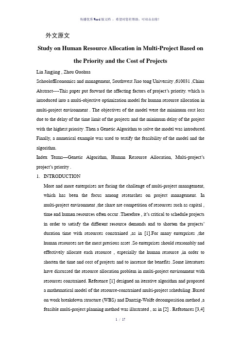
外文原文Study on Human Resource Allocation in Multi-Project Based on the Priority and the Cost of ProjectsLin Jingjing , Zhou GuohuaSchoolofEconomics and management, Southwest Jiao tong University ,610031 ,China Abstract----This paper put forward the a ffecting factors of project’s priority. which is introduced into a multi-objective optimization model for human resource allocation in multi-project environment . The objectives of the model were the minimum cost loss due to the delay of the time limit of the projects and the minimum delay of the project with the highest priority .Then a Genetic Algorithm to solve the model was introduced. Finally, a numerical example was used to testify the feasibility of the model and the algorithm.Index Terms—Genetic Algorithm, Human Resource Allocation, Multi-project’s project’s priority .1.INTRODUCTIONMore and more enterprises are facing the challenge of multi-project management, which has been the focus among researches on project management. In multi-project environment ,the share are competition of resources such as capital , time and human resources often occur .Therefore , it’s critical to schedule projects in order to satisfy the different resource demands and to shorten the projects’ duration time with resources constrained ,as in [1].For many enterprises ,the human resources are the most precious asset .So enterprises should reasonably and effectively allocate each resource , especially the human resource ,in order to shorten the time and cost of projects and to increase the benefits .Some literatures have discussed the resource allocation problem in multi-project environment with resources constrained. Reference [1] designed an iterative algorithm and proposeda mathematical model of the resource-constrained multi-project scheduling .Basedon work breakdown structure (WBS) and Dantzig-Wolfe decomposition method ,a feasible multi-project planning method was illustrated , as in [2] . References [3,4]discussed the resource-constrained project scheduling based on Branch Delimitation method .Reference [5] put forward the framework of human resource allocation in multi-project in Long-term ,medium-term and short-term as well as research and development(R&D) environment .Basedon GPSS language, simulation model of resources allocation was built to get the project’s duration time and resources distribution, as in [6]. Reference [7] solved the engineering project’s resources optimization problem using Genetic Algorithms. These literatures reasonably optimized resources allocation in multi-project, but all had the same prerequisite that the project’s importance is the same to each other .This paper will analyze the effects of project’s priority on human resource allocation ,which is to be introduced into a mathematical model ;finally ,a Genetic Algorithm is used to solve the model.2.EFFECTS OF PROJECTS PRIORITY ON HUMAN RESOUCE ALLOCATIONAND THE AFFECTING FACTORS OF PROJECT’S PRIORITYResource sharing is one of the main characteristics of multi-project management .The allocation of shared resources relates to the efficiency and rationality of the use of resources .When resource conflict occurs ,the resource demand of the project with highest priority should be satisfied first. Only after that, can the projects with lower priority be considered.Based on the idea of project classification management ,this paper classifies the affecting factors of project’s priority into three categories ,as the project’s benefits ,the complexity of project management and technology , and the strategic influence on the enterprise’s future development . The priority weight of the project is the function of the above three categories, as shown in (1).W=f(I,c,s…) (1)Where w refers to project’s priority weight; I refers to the benefits of th e project; c refers to the complexity of the project, including the technology and management; s refers to the influence of the project on enterprise .The bigger the values of the three categories, the higher the priority is.3.HUMAN RESOURCE ALLOCATION MODEL IN MULTI-PROJECTENVIRONMENT3.1Problem DescriptionAccording to the constraint theory, the enterprise should strictly differentiate the bottleneck resources and the non-bottleneck resources to solve the constraint problem of bottleneck resources .This paper will stress on the limited critical human resources being allocated to multi-project with definite duration times and priority.To simplify the problem, we suppose that that three exist several parallel projects and a shared resources storehouse, and the enterprise’s operation only involves one kind of critical human resources. The supply of the critical human resource is limited, which cannot be obtained by hiring or any other ways during a certain period .when resource conflict among parallel projects occurs, we may allocate the human resource to multi-project according to project’s priorities .The allocation of non-critical independent human resources is not considered in this paper, which supposes that the independent resources that each project needs can be satisfied.Engineering projects usually need massive critical skilled human resources in some critical chain ,which cannot be substituted by the other kind of human resources .When the critical chains of projects at the same time during some period, there occur resource conflict and competition .The paper also supposes that the corresponding network planning of various projects have already been established ,and the peaks of each project’s resources demand have been optimized .The delay of the critical chain will affect the whole project’s duration time .3.2 Model HypothesesThe following hypotheses help us to establish a mathematical model:(1)The number of mutually independent projects involved in resourceallocation problem in multi-project is N. Each project is indicated withQ i,while i=1,2, … N.(2)The priority weights of multi-project have been determined ,which arerespectively w1,w 2…w n .(3) The total number of the critical human resources is R ,with r k standingfor each person ,while k=1,2, …,R(4) Δk i = ⎩⎨⎧others toprojectQ rcer humanresou i k 01(5) Resources capturing by several projects begins on time. t E i is theexpected duration time of project I that needs the critical resources tofinish some task after time t ,on the premise that the human resourcesdemand can be satisfied .tAi is the real duration time of project I thatneeds the critical resource to finish some task after time t .(6) According to the contract ,if the delay of the project happens the dailycost loss due to the delay is △c i for pro ject I .According to the project’simportance ,the delay of a project will not only cause the cost loss ,butwill also damage the prestige and status of the enterprise .(while thelatent cost is difficult to quantify ,it isn’t considered in this articletemporarily.)(7) From the hypothesis (5) ,we can know that after time t ,the time-gapbetween the real and expected duration time of project I that needs thecritical resources to finish some task is △t i ,( △t i =t A i -t E i ). For thereexists resources competition, the time –gap is necessarily a positivenumber.(8) According to hypotheses (6) and (7), the total cost loss of project I is C i(C i = △t i * △C i ).(9) The duration time of activities can be expressed by the workload ofactivities divided by the quantity of resources ,which can be indicatedwith following expression of t A i =ηi / R i * ,.In the expression , ηi refersto the workload of projects I during some period ,which is supposed tobe fixed and pre-determined by the project managers on project planningphase ; R i * refers to the number of the critical human resources beingallocated to projects I actually, with the equation Ri * =∑=Rk ki 1δ existing. Due to the resource competition the resourcedemands of projects with higherPriorities may be guarantee, while those projects with lower prioritiesmay not be fully guaranteed. In this situation, the decrease of theresource supply will lead to the increase of the duration time of activitiesand the project, while the workload is fixed.3.3 Optimization ModelBased on the above hypotheses, the resource allocation model inmulti-project environment can be established .Here, the optimizationmodel is :F i =min Z i = min∑∑==Ni i N i Ci 11ω =min i i Ni i N i c t ∆∆∑∑==11ω (2) =min ∑∑==N i i N i 11ω )E i R i ki i t - ⎝⎛∑=1δη i c ∆ 2F =min Z 2=min ()i t ∆=min )E i R i ki i t -⎝⎛∑=1δη (3) Where wj=max(wi) ,(N j i 3,2,1,=∀) (4)Subject to : 0∑∑==≤R k ki N i 11δ=R (5)The model is a multi-objective one .The two objective functions arerespectively to minimize the total cost loss ,which is to conform to theeconomic target ,and to shorten the time delay of the project with highestpriority .The first objective function can only optimize the apparenteconomic cost ;therefore the second objective function will help to makeup this limitation .For the project with highest priority ,time delay will damage not only the economic benefits ,but also the strategy and the prestige of the enterprise .Therefore we should guarantee that the most important project be finished on time or ahead of schedule .4.SOLUTION TO THE MULTI-OBJECTIVE MODEL USING GENETICALGORITHM4.1The multi-objective optimization problem is quite common .Generally ,eachobjective should be optimized in order to get the comprehensive objective optimized .Therefore the weight of each sub-objective should be considered .Reference [8] proposed an improved ant colony algorithm to solve this problem .Supposed that the weights of the two optimizing objectives are αand β ,where α+β=1 .Then the comprehensive goal is F* ,where F*=αF1+βF2.4.2The Principle of Genetic AlgorithmGenetic Algorithm roots from the concepts of natural selection and genetics .It’s a random search technique for global optimization in a complex search space .Because of the parallel nature and less restrictions ,it has the key features of great currency ,fast convergence and easy calculation .Meanwhile ,its search scope is not limited ,so it’s an effective method to solve the resource balancing problem ,as in [9].The main steps of GA in this paper are as follow:(1)EncodingAn integer string is short, direct and efficient .According to thecharacteristics of the model, the human resource can be assigned to be acode object .The string length equals to the total number of humanresources allocated.(2)Choosing the fitness functionThis paper choose the objective function as the foundation of fitnessfunction .To rate the values of the objective function ,the fitness of then-th individual is 1/n。
建筑设计毕业论文中英文资料外文翻译文献
毕业论文中英文资料外文翻译文献Architecture StructureWe have and the architects must deal with the spatial aspect of activity, physical, and symbolic needs in such a way that overall performance integrity is assured. Hence, he or she well wants to think of evolving a building environment as a total system of interacting and space forming subsystems. Is represents a complex challenge, and to meet it the architect will need a hierarchic design process that provides at least three levels of feedback thinking: schematic, preliminary, and final.Such a hierarchy is necessary if he or she is to avoid being confused , at conceptual stages of design thinking ,by the myriad detail issues that can distract attention from more basic consideration s .In fact , we can say that an architect’s ability to distinguish the more basic form the more detailed issues is essential to his success as a designer .The object of the schematic feed back level is to generate and evaluate overall site-plan, activity-interaction, and building-configuration options .To do so the architect must be able to focus on the interaction of the basic attributes of the site context, the spatial organization, and the symbolism as determinants of physical form. This means that ,in schematic terms ,the architect may first conceive and model a building design as an organizational abstraction of essential performance-space in teractions.Then he or she may explore the overall space-form implications of the abstraction. As an actual building configuration option begins to emerge, it will be modified to include consideration for basic site conditions.At the schematic stage, it would also be helpful if the designer could visualize his or her options for achieving overall structural integrity and consider the constructive feasibility and economic of his or her scheme .But this will require that the architect and/or a consultant be able to conceptualize total-system structural options in terms of elemental detail .Such overall thinking can be easily fed back to improve the space-form scheme.At the preliminary level, the architect’s emphasis will shift to the elaboration of his or her more promising schematic design options .Here the architect’s structural needs will shift toapproximate design of specific subsystem options. At this stage the total structural scheme is developed to a middle level of specificity by focusing on identification and design of major subsystems to the extent that their key geometric, component, and interactive properties are established .Basic subsystem interaction and design conflicts can thus be identified and resolved in the context of total-system objectives. Consultants can play a significant part in this effort; these preliminary-level decisions may also result in feedback that calls for refinement or even major change in schematic concepts.When the designer and the client are satisfied with the feasibility of a design proposal at the preliminary level, it means that the basic problems of overall design are solved and details are not likely to produce major change .The focus shifts again ,and the design process moves into the final level .At this stage the emphasis will be on the detailed development of all subsystem specifics . Here the role of specialists from various fields, including structural engineering, is much larger, since all detail of the preliminary design must be worked out. Decisions made at this level may produce feedback into Level II that will result in changes. However, if Levels I and II are handled with insight, the relationship between the overall decisions, made at the schematic and preliminary levels, and the specifics of the final level should be such that gross redesign is not in question, Rather, the entire process should be one of moving in an evolutionary fashion from creation and refinement (or modification) of the more general properties of a total-system design concept, to the fleshing out of requisite elements and details.To summarize: At Level I, the architect must first establish, in conceptual terms, the overall space-form feasibility of basic schematic options. At this stage, collaboration with specialists can be helpful, but only if in the form of overall thinking. At Level II, the architect must be able to identify the major subsystem requirements implied by the scheme and substantial their interactive feasibility by approximating key component properties .That is, the properties of major subsystems need be worked out only in sufficient depth to very the inherent compatibility of their basic form-related and behavioral interaction . This will mean a somewhat more specific form of collaboration with specialists then that in level I .At level III ,the architect and the specific form of collaboration with specialists then that providing for all of the elemental design specifics required to produce biddable construction documents .Of course this success comes from the development of the Structural Material.1.Reinforced ConcretePlain concrete is formed from a hardened mixture of cement ,water ,fine aggregate, coarse aggregate (crushed stone or gravel),air, and often other admixtures. The plastic mix is placed and consolidated in the formwork, then cured to facilitate the acceleration of the chemical hydration reaction lf the cement/water mix, resulting in hardened concrete. The finished product has high compressive strength, and low resistance to tension, such that its tensile strength is approximately one tenth lf its compressive strength. Consequently, tensile and shear reinforcement in the tensile regions of sections has to be provided to compensate for the weak tension regions in the reinforced concrete element.It is this deviation in the composition of a reinforces concrete section from the homogeneity of standard wood or steel sections that requires a modified approach to the basic principles of structural design. The two components of the heterogeneous reinforced concrete section are to be so arranged and proportioned that optimal use is made of the materials involved. This is possible because concrete can easily be given any desired shape by placing and compacting the wet mixture of the constituent ingredients are properly proportioned, the finished product becomes strong, durable, and, in combination with the reinforcing bars, adaptable for use as main members of any structural system.The techniques necessary for placing concrete depend on the type of member to be cast: that is, whether it is a column, a bean, a wall, a slab, a foundation. a mass columns, or an extension of previously placed and hardened concrete. For beams, columns, and walls, the forms should be well oiled after cleaning them, and the reinforcement should be cleared of rust and other harmful materials. In foundations, the earth should be compacted and thoroughly moistened to about 6 in. in depth to avoid absorption of the moisture present in the wet concrete. Concrete should always be placed in horizontal layers which are compacted by means of high frequency power-driven vibrators of either the immersion or external type, as the case requires, unless it is placed by pumping. It must be kept in mind, however, that over vibration can be harmful since it could cause segregation of the aggregate and bleeding of the concrete.Hydration of the cement takes place in the presence of moisture at temperatures above 50°F. It is necessary to maintain such a condition in order that the chemical hydration reaction can take place. If drying is too rapid, surface cracking takes place. This would result in reduction of concrete strength due to cracking as well as the failure to attain full chemical hydration.It is clear that a large number of parameters have to be dealt with in proportioning a reinforced concrete element, such as geometrical width, depth, area of reinforcement, steel strain, concrete strain, steel stress, and so on. Consequently, trial and adjustment is necessary in the choice ofconcrete sections, with assumptions based on conditions at site, availability of the constituent materials, particular demands of the owners, architectural and headroom requirements, the applicable codes, and environmental reinforced concrete is often a site-constructed composite, in contrast to the standard mill-fabricated beam and column sections in steel structures.A trial section has to be chosen for each critical location in a structural system. The trial section has to be analyzed to determine if its nominal resisting strength is adequate to carry the applied factored load. Since more than one trial is often necessary to arrive at the required section, the first design input step generates into a series of trial-and-adjustment analyses.The trial-and –adjustment procedures for the choice of a concrete section lead to the convergence of analysis and design. Hence every design is an analysis once a trial section is chosen. The availability of handbooks, charts, and personal computers and programs supports this approach as a more efficient, compact, and speedy instructional method compared with the traditional approach of treating the analysis of reinforced concrete separately from pure design.2. EarthworkBecause earthmoving methods and costs change more quickly than those in any other branch of civil engineering, this is a field where there are real opportunities for the enthusiast. In 1935 most of the methods now in use for carrying and excavating earth with rubber-tyred equipment did not exist. Most earth was moved by narrow rail track, now relatively rare, and the main methods of excavation, with face shovel, backacter, or dragline or grab, though they are still widely used are only a few of the many current methods. To keep his knowledge of earthmoving equipment up to date an engineer must therefore spend tine studying modern machines. Generally the only reliable up-to-date information on excavators, loaders and transport is obtainable from the makers.Earthworks or earthmoving means cutting into ground where its surface is too high ( cuts ), and dumping the earth in other places where the surface is too low ( fills). Toreduce earthwork costs, the volume of the fills should be equal to the volume of the cuts and wherever possible the cuts should be placednear to fills of equal volume so as to reduce transport and double handlingof the fill. This work of earthwork design falls on the engineer who lays out the road since it is the layout of the earthwork more than anything else which decides its cheapness. From the available maps ahd levels, the engineering must try to reach as many decisions as possible in the drawing office by drawing cross sections of the earthwork. On the site when further information becomes available he can make changes in jis sections and layout,but the drawing lffice work will not have been lost. It will have helped him to reach the best solution in the shortest time.The cheapest way of moving earth is to take it directly out of the cut and drop it as fill with the same machine. This is not always possible, but when it canbe done it is ideal, being both quick and cheap. Draglines, bulldozers and face shovels an do this. The largest radius is obtained with thedragline,and the largest tonnage of earth is moved by the bulldozer, though only over short distances.The disadvantages of the dragline are that it must dig below itself, it cannot dig with force into compacted material, it cannot dig on steep slopws, and its dumping and digging are not accurate.Face shovels are between bulldozers and draglines, having a larger radius of action than bulldozers but less than draglines. They are anle to dig into a vertical cliff face in a way which would be dangerous tor a bulldozer operator and impossible for a dragline. Each piece of equipment should be level of their tracks and for deep digs in compact material a backacter is most useful, but its dumping radius is considerably less than that of the same escavator fitted with a face shovel.Rubber-tyred bowl scrapers are indispensable for fairly level digging where the distance of transport is too much tor a dragline or face shovel. They can dig the material deeply ( but only below themselves ) to a fairly flat surface, carry it hundreds of meters if need be, then drop it and level it roughly during the dumping. For hard digging it is often found economical to keep a pusher tractor ( wheeled or tracked ) on the digging site, to push each scraper as it returns to dig. As soon as the scraper is full,the pusher tractor returns to the beginning of the dig to heop to help the nest scraper.Bowl scrapers are often extremely powerful machines;many makers build scrapers of 8 cubic meters struck capacity, which carry 10 m ³ heaped. The largest self-propelled scrapers are of 19 m ³struck capacity ( 25 m ³ heaped )and they are driven by a tractor engine of 430 horse-powers.Dumpers are probably the commonest rubber-tyred transport since they can also conveniently be used for carrying concrete or other building materials. Dumpers have the earth container over the front axle on large rubber-tyred wheels, and the container tips forwards on most types, though in articulated dumpers the direction of tip can be widely varied. The smallest dumpers have a capacity of about 0.5 m ³, and the largest standard types are of about 4.5 m ³. Special types include the self-loading dumper of up to 4 m ³ and the articulated type of about 0.5 m ³. The distinction between dumpers and dump trucks must be remembered .dumpers tip forwards and the driver sits behind the load. Dump trucks are heavy, strengthened tipping lorries, the driver travels in front lf the load and the load is dumped behind him, so they are sometimes called rear-dump trucks.3.Safety of StructuresThe principal scope of specifications is to provide general principles and computational methods in order to verify safety of structures. The “ safety factor ”, which according to modern trends is independent of the nature and combination of the materials used, can usually be defined as the ratio between the conditions. This ratio is also proportional to the inverse of the probability ( risk ) of failure of the structure.Failure has to be considered not only as overall collapse of the structure but also asunserviceability or, according to a more precise. Common definition. As the reaching of a “ limit state ” which causes the construction not to accomplish the task it was designed for. Ther e are two categories of limit state :(1)Ultimate limit sate, which corresponds to the highest value of the load-bearing capacity. Examples include local buckling or global instability of the structure; failure of some sections and subsequent transformation of the structure into a mechanism; failure by fatigue; elastic or plastic deformation or creep that cause a substantial change of the geometry of the structure; and sensitivity of the structure to alternating loads, to fire and to explosions.(2)Service limit states, which are functions of the use and durability of the structure. Examples include excessive deformations and displacements without instability; early or excessive cracks; large vibrations; and corrosion.Computational methods used to verify structures with respect to the different safety conditions can be separated into:(1)Deterministic methods, in which the main parameters are considered as nonrandom parameters.(2)Probabilistic methods, in which the main parameters are considered as random parameters.Alternatively, with respect to the different use of factors of safety, computational methods can be separated into:(1)Allowable stress method, in which the stresses computed under maximum loads are compared with the strength of the material reduced by given safety factors.(2)Limit states method, in which the structure may be proportioned on the basis of its maximum strength. This strength, as determined by rational analysis, shall not be less than that required to support a factored load equal to the sum of the factored live load and dead load ( ultimate state ).The stresses corresponding to working ( service ) conditions with unfactored live and dead loads are compared with prescribed values ( service limit state ) . From the four possible combinations of the first two and second two methods, we can obtain some useful computational methods. Generally, two combinations prevail:(1)deterministic methods, which make use of allowable stresses.(2)Probabilistic methods, which make use of limit states.The main advantage of probabilistic approaches is that, at least in theory, it is possible to scientifically take into account all random factors of safety, which are then combined to define the safety factor. probabilistic approaches depend upon :(1) Random distribution of strength of materials with respect to the conditions of fabrication and erection ( scatter of the values of mechanical properties through out the structure );(2) Uncertainty of the geometry of the cross-section sand of the structure ( faults andimperfections due to fabrication and erection of the structure );(3) Uncertainty of the predicted live loads and dead loads acting on the structure;(4)Uncertainty related to the approximation of the computational method used ( deviation of the actual stresses from computed stresses ).Furthermore, probabilistic theories mean that the allowable risk can be based on several factors, such as :(1) Importance of the construction and gravity of the damage by its failure;(2)Number of human lives which can be threatened by this failure;(3)Possibility and/or likelihood of repairing the structure;(4) Predicted life of the structure.All these factors are related to economic and social considerations such as:(1) Initial cost of the construction;(2) Amortization funds for the duration of the construction;(3) Cost of physical and material damage due to the failure of the construction;(4) Adverse impact on society;(5) Moral and psychological views.The definition of all these parameters, for a given safety factor, allows construction at the optimum cost. However, the difficulty of carrying out a complete probabilistic analysis has to be taken into account. For such an analysis the laws of the distribution of the live load and its induced stresses, of the scatter of mechanical properties of materials, and of the geometry of the cross-sections and the structure have to be known. Furthermore, it is difficult to interpret the interaction between the law of distribution of strength and that of stresses because both depend upon the nature of the material, on the cross-sections and upon the load acting on the structure. These practical difficulties can be overcome in two ways. The first is to apply different safety factors to the material and to the loads, without necessarily adopting the probabilistic criterion. The second is an approximate probabilistic method which introduces some simplifying assumptions ( semi-probabilistic methods ) .文献翻译建筑师必须从一种全局的角度出发去处理建筑设计中应该考虑到的实用活动,物质及象征性的需求。
建筑英文文献及翻译

建筑英文文献及翻译第一篇:建筑英文文献及翻译外文原文出处: NATO Science for Peace and Security Series C: Environmental Security, 2009, Increasing Seismic Safety by Combining Engineering Technologies and Seismological Data, Pages 147-149动力性能对建筑物的破坏引言:建筑物在地震的作用下,和一些薄弱的建筑结构中,动力学性能扮演了一个很重要的角色。
特别是要满足最基本的震动周期,无论是在设计的新建筑,或者是评估已经有的建筑,使他们可以了解地震的影响。
许多标准(例如:欧标,2003;欧标,2006),建议用简单的表达式来表达一个建筑物的高度和他的基本周期。
这样的表达式被牢记在心,得出标定设计(高尔和乔谱拉人,1997),从而人为的低估了标准周期。
因为这个原因,他们通常提供比较低的设计标准当与那些把设计基础标准牢记在心的人(例:乔普拉本和高尔,2000)。
当后者从已进行仔细建立的数字模型中得到数值(例:克劳利普和皮诺,2004;普里斯特利权威,2007)。
当数字估计与周围震动测量的实验结果相比较,有大的差异,提供非常低的周期标准(例:纳瓦洛苏达权威,2004)。
一个概述不同的方式比较确切的结果刊登在马西和马里奥(2008);另外,一个高级的表达式来指定更有说服力的坚固建筑类型,提出了更加准确的结构参数表(建筑高度,开裂,空隙填实,等等)。
联系基础和上层建筑的震动周期可能发生共振的效果。
这个原因对于他们的振动,可能建筑物和土地在非线性运动下受到到破坏,这个必须被重视。
通常,结构工程师和岩土工程师有不同的观点在共振作用和一些变化的地震活动。
结构工程师们认为尽管建筑物和土壤的自振周期和地震周期都非常的接近。
但对于建筑物周期而言,到底是因为结构还是非结构造成的破坏提出了疑问。
土木工程高层建筑中英文对照外文翻译文献
中英文资料翻译1外文资料The Tall Office Building Artistically ConsideredThe architects of this land and generation are now brought face to face with something new under the sun namely, that evolution and integration of social conditions, that special grouping of them, that results in a demand for the erection of tall office buildings.It is not my purpose to discuss the social conditions; I accept them as the fact, and say at once that the design of the tall office building must be recognized and confronted at the outset as a problem to be solved a vital problem, pressing for a true solution.Let us state the conditions in the plainest manner. Briefly, they are these: offices are necessary for the transaction of business; the invention and perfection of the high speed elevators make vertical travel, that was once tedious and painful, now easy and comfortable; development of steel manufacture has shown the way to safe, rigid, economical constructions rising to a great height; continued growth of population in the great cities, consequent congestion of centers and rise in value of ground, stimulate an increase in number of stories; these successfully piled one upon another, react on ground values and so on, byaction and reaction, interaction and inter reaction. Thus has come about that form of lofty construction called the "modern office building". It has come in answer to a call, for in it a new grouping of social conditions has found a habitation and a name.Up to this point all in evidence is materialistic, an exhibition of force, of resolution, of brains in the keen sense of the word. It is the joint product of the speculator, the engineer, the builder.Problem: How shall we impart to this sterile pile, this crude, harsh, brutal agglomeration, this stark, staring exclamation of eternal strife, the graciousness of these higher forms of sensibility and culture that rest on the lower and fiercer passions? How shall we proclaim from the dizzy height of this strange, weird, modern housetop the peaceful evangel of sentiment, of beauty, the cult of a higher life?This is the problem; and we must seek the solution of it in a process analogous to its own evolution indeed, a continuation of it namely, by proceeding step by step from general to special aspects, from coarser to finer considerations.It is my belief that it is of the very essence of every problem that is contains and suggests its own solution. This I believe to be natural law. Let us examine, then, carefully the elements, let us search out this contained suggestion, this essence of the problem.The practical conditions are, broadly speaking, these:Wanted 1st, a story below ground, containing boiler, engines of various sorts, etc. in short, the plant for power, heating, lighting, etc. 2nd, a ground floor, so called, devoted to stores, banks, or other establishments requiring large area, ample spacing, ample light, and great freedom of access, 3rd, a second story readily accessible by stairways this space usually in large subdivisions, with corresponding liberality in structural spacing and expanse of glass and breadth of external openings, 4th, above this an indefinite number of stories of offices piled tier upon tier, one tier just like another tier, one office just like all the other offices an office being similar to a cell in honey comb, merely a compartment, nothing more, 5th, and last, at the top of this pile is placed a space or story that, as related to the life and usefulness of the structure, is purely physiological in its nature namely, the attic. In this the circulatory system completes itself and makes it grand turn, ascending and descending. The space is filled with tanks, pipes, valves, sheaves, and mechanical etcetera that supplement and complement the force originating plant hidden below ground in the cellar. Finally, or at the beginning rather, there must be on the ground floor a main aperture or entrance common to all the occupants or patrons of the building.This tabulation is, in the main, characteristic of every tall office building in the country. As to the necessary arrangements for light courts, these are not germane to the problem, and as will become soon evident, I trust need not be considered here. These things, and such others as the arrangement of elevators, for example, have to do strictly with the economics of the building, and I assumethem to have been fully considered and disposed of to the satisfaction of purely utilitarian and pecuniary demands. Only in rare instances does the plan or floor arrangement of the tall office building take on an aesthetic value, and thus usually when the lighting court is external or becomes an internal feature of great importance.As I am here seeking not for an individual or special solution, but for a true normal type, the attention must be confined to those conditions that, in the main, are constant in all tall office buildings, and every mere incidental and accidental variation eliminated from the consideration, as harmful to the clearness of the main inquiry.The practical horizontal and vertical division or office unit is naturally based on a room of comfortable area and height, and the size of this standard office room as naturally predetermines the standard structural unit, and, approximately, the size of window openings. In turn, these purely arbitrary units of structure form in an equally natural way the true basis of the artistic development of the exterior. Of course the structural spacings and openings in the first or mercantile story are required to be the largest of all; those in the second or quasi mercantile story are of a some what similar nature. The spacings and openings in the attic are of no importance whatsoever the windows have no actual value, for light may be taken from the top, and no recognition of a cellular division is necessary in the structural spacing.Hence it follow inevitably, and in the simplest possible way, that if wefollow our natural instincts without thought of books, rules, precedents, or any such educational impediments to a spontaneous and "sensible" result, we will in the following manner design the exterior of our tall office building to wit: Beginning with the first story, we give this a min entrance that attracts the eye to it location, and the remainder of the story we treat in a more or less liberal, expansive, sumptuous way a way based exactly on the practical necessities, but expressed with a sentiment of largeness and freedom. The second story we treat in a similar way, but usually with milder pretension. Above this, throughout the indefinite number of typical office tiers, we take our cue from the individual cell, which requires a window with its separating pier, its still and lintel, and we, without more ado, make them look all alike because they are all alike. This brings us to the attic, which having no division into office cells, and no special requirement for lighting, gives us the power to show by means of its broad expanse of wall, and its dominating weight and character, that which is the fact namely, that the series of office tiers has come definitely to an end.This may perhaps seem a bald result and a heartless, pessimistic way of stating it, but even so we certainly have advanced a most characteristic stage beyond the imagined sinister building of the speculator engineer builder combination. For the hand of the architect is now definitely felt in the decisive position at once taken, and the suggestion of a thoroughly sound, logical, coherent expression of the conditions is becoming apparent.When I say the hand of the architect, I do not mean necessarily theaccomplished and trained architect. I mean only a man with a strong, natural liking for buildings, and a disposition to shape them in what seems to his unaffected nature a direct and simple way. He will probably tread an innocent path from his problem to its solution, and therein he will show an enviable gift of logic. If we have some gift for form in detail, some feeling for form purely and simply as form, some love for that, his result in addition to it simple straightforward naturalness and completeness in general statement, will have something of temperament and interest.However, thus far the results are only partial and tentative at best relatively true, they are but superficial. We are doubtless right in our instinct but we must seek a fuller justification, a finer sanction, for it.I assume now that in the study of our problem we have passed through the various stages of inquiry, as follows: 1st, the social basis of the demand for tall buildings; 2nd, its literal material satisfaction; 3rd, the elevation of the question from considerations of literal planning, construction, and equipment, to the plane of elementary architecture as a direct outgrowth of sound, sensible building; 4th, the question again elevated from an elementary architecture to the beginnings of true architectural expression, through the addition of a certain quality and quantity of sentiment.But our building may have all these in a considerable degree and yet be far from that adequate solution of the problem I am attempting to define. We must now heed quality and quantity of sentiment.It demands of us, what is the chief characteristic of the tall office building? And at once we answer, it is lofty. This loftiness is to the artist nature its thrilling aspect. It is the very open organ tone in its appeal. It must be in turn the dominant chard in his expression of it, the true excitant of his imagination. It must be tall, every inch of it tall. The force and power of altitude must be in it, the glory and pride of exaltation must be in it. It must be every inch a proud and soaring thing, rising in sheer exultation that from bottom to top it is a unit without a single dissenting line that it is the new, the unexpected, the eloquent peroration of most bald, most sinister, most forbidding conditions.The man who designs in the spirit and with the sense of responsibility to the generation he lives in must be no coward, no denier, no bookworm, no dilettante. He must live of his life and for his life in the fullest, most consummate sense. He must realize at once and with the grasp of inspiration that the problem of the tall office building is one of the most stupendous, one of the most magnificent opportunities that the Lord of Nature in His beneficence has ever offered to the proud spirit of man.That this has not been perceived indeed has been flatly denied is an exhibition of human perversity that must give us pause.One more consideration. Let us now lift this question into the region of calm, philosophic observation. Let us seek a comprehensive, a final solution: let the problem indeed dissolve.Certain critics, and very thoughtful ones, have advanced the theory that thetrue prototype of the tall office building is the classical column, consisting of base, shaft and capital the molded base of the column typical of the lower stories of our building, the plain or fluted shaft suggesting the monotonous, uninterrupted series of office tiers, and the capital the completing power and luxuriance of the attic.Other theorizers, assuming a mystical symbolism as a guide, quite the many trinities in nature and art, and the beauty and conclusiveness of such trinity in unity. They aver the beauty of prime numbers, the mysticism of the number three, the beauty of all things that are in three parts to wit, the day, subdividing into morning, noon, and night; the limbs, the thorax, and the head, constituting the body. So they say, should the building be in three parts vertically, substantially as before, but for different motives.Others, of purely intellectual temperament, hold that such a design should be in the nature of a logical statement; it should have a beginning, a middle, and an ending, each clearly defined therefore again a building, as above, in three parts vertically.2中文翻译高层办公建筑艺术思考这个时代该领域的建筑师开始正视一些新的由于社会条件变革和整合以及它们特殊组合导致的对高层办公建筑的立面要求。
- 1、下载文档前请自行甄别文档内容的完整性,平台不提供额外的编辑、内容补充、找答案等附加服务。
- 2、"仅部分预览"的文档,不可在线预览部分如存在完整性等问题,可反馈申请退款(可完整预览的文档不适用该条件!)。
- 3、如文档侵犯您的权益,请联系客服反馈,我们会尽快为您处理(人工客服工作时间:9:00-18:30)。
中英文对照外文翻译文献(文档含英文原文和中文翻译)原文:Housing Problems and Options for the Elderly 1. IntroductionHousing is a critical element in the lives of older persons. The affordability of housing affects the ability of the elderly to afford other necessities of life such as food and medical care. Housing that is located near hospitals and doctors, shopping, transportation, and recreational facilities can facilitate access to services that can enhance the quality of life. Housing can also be a place of memories of the past and a connection to friends and neighbors. Housing with supportive features and access to services can also make it possible for persons to age in place. In this session, we will be examining housing problems andoptions for the elderly. Along the way, we will be testing your housing IQ with a series of questions and exercises.2. Housing Situation of Older PersonsHow typical is the housing situation of the olders?We will begin by examining five areas :(1)Prevalence of home ownership (2)Length of stay in current residence (3)Living arrangements (4)Attachments of older persons to where they live (5)Moving behavior.With whom older persons live can influence housing affordability, space needs, and the ability to age in place. About 54% of older persons live with their spouses, 31% live alone, almost 13% live with related persons other than their spouse and about 2% live with unrelated persons. With increasing age, older persons (primarily women) are more likely to live alone or with a relative other than a spouse. Frail older women living alone are the persons most likely to reside in homes with ‘extra’ rooms and to need both physically supportive housing features and services to "age in place". This segment of the population is also the group most likely to move to more supportive housing settings such as assisted living.Many older persons have strong psychological attachments to their homes related to length of residence. The home often represents the place where they raised their children and a lifetime of memories. It is also a connection to an array of familiar persons such as neighbors and shopkeepers as well as near by places including houses of worship, libraries and community services. For manyolder persons, the home is an extension of their own personalities which is found in the furnishings . In addition, the home can represent a sense of economic security for the future, especially for homeowners who have paid off their mortgages. For owners, the home is usually their most valuable financial asset. The home also symbolizes a sense of independence in that the resident is able to live on his or her own. For these types of reasons, it is understandable that in response to a question about housing preferences, AARP surveys of older persons continue to find that approximately 80% of older persons report that what they want is to "stay in their own homes and never move." This phenomena has been termed the preference to "age in place."Although most older persons move near their current communities, some seek retirement communities in places with warmer weather in the southwest, far west and the south.3. The Federal Government's Housing Programs for the ElderlyThe federal government has had two basic housing strategies to address housing problems of the elderly. One strategy, termed the "supply side" approach, seeks to build new housing complexes such as public housing and Section 202 housing for older persons. Public housing is administered by quasi-governmental local public housing authorities. Section 202 Housing for the elderly and disabled is sponsored by non-profit organizations including religious and non-sectarian organizations. Approximately 1.5 million olderpersons or 3% of the elderly population live in federally assisted housing, with about 387,000 living in Section 202 housing. Over time, the government has shifted away from such new construction programs because of the cost of such housing, the problems that a number of non-elderly housing programs have experienced, and a philosophy that the government should no longer be directly involved with the building of housing. Section 202 housing, a very popular and successful program, is one of the few supply-side programs funded by the federal government, although the budget allocation during the last ten years has allowed for the construction of only about 6,000 units per year compared to a high of almost 20,000 units in the late 1970s. Instead of funding new construction, federal housing initiatives over the last decade have emphasized ‘demand side’ subsidies that provide low-income renters with a certificate or a voucher that they can use in a variety of multiunit settings, including apartments in the private sector that meet rental and condition guidelines. These vouchers and certificates are aimed at reducing excessive housing costs. Some certificates are termed ‘project based’ subsidies and are tied to federally subsidized housing such as Section 202. Because housing programs are not an entitlement, however, supply-side and demand side programs together are only able to meet the needs of about 1/3 of elderly renters who qualify on the basis of income.While advocates for housing have been trying to hold on to the existing programs in the face of huge budget cuts at HUD, much of the attention has been shifting towards meeting the shelter and service needs of the frail elderly. This emphasis reflects the increasing number of older persons in their eightiesand nineties who need a physically supportive environment linked with services. This group of older persons includes a high percentage of older residents of public and Section 202 housing. Initially built for independent older persons who were initially in the late sixties and early seventies, this type of housing now includes older persons in their eighties and nineties, many of whom have aged in place. Consequently, the government is faced with creating strategies to bring services into these buildings and retrofit them to better suit the needs of frail older persons. A major initiative of the early 1990s, which may be stalled by current budget problems at HUD, has been for the federal government to pay for service coordinators to assess the needs of residents of government assisted housing complexes and link them with services. As of 1998, there were approximately 1,000 service coordinators attached to government assisted housing complexes across the country.4. The Housing Continuum: A Range of Options for ElderlyA long-standing assumption in the field of housing has been that as persons become more frail, they will have to move along a housing continuum from one setting to another. As the figure on housing options suggests, along this continuum are found a range of housing options including single family homes, apartments, congregate living, assisted living, and board and care homes (Kendig & Pynoos, 1996). The end point of the housing continuum has been thenursing home. These options vary considerably in terms of their availability, affordability, and ability to meet the needs of very frail older persons.The concept of a continuum of supportive care is based on the assumption that housing options can be differentiated by the amount and types of services offered; the supportiveness of the physical setting in terms of accessibility, features, and design; and the competency level of the persons to whom the housing is targeted. The figure on housing options indicates how such options generally meet the needs of older persons who are categorized,as independent, semi-dependent and dependent. Semi-dependent older persons can be thought of as needing some assistance from other persons with instrumental activities of daily living (IADLs) such as cooking, cleaning, and shopping. In addition to needing assistance with some IADLs, dependent older persons may require assistance with more basic activities such as toileting, eating and bathing. Although semi-dependent and dependent older persons can be found throughout the housing continuum, independent older persons are very unlikely to reside in housing types such as assisted living specifically designed and equipped to meet the needs of frail older persons unless their spouses require these needs.Although the continuum of housing identifies a range of housing types, there is increasing recognition that frail older persons do not necessarily have to move from one setting to another if they need assistance. Semi-dependent or dependent older persons can live in a variety of settings, including their own homes and apartments, if the physical environment is made more supportive, caregivers are available to provide assistance and affordable services areaccessible.5. ConclusionsHousing plays a critical role in the lives of older persons. Most older homeowners who function independently express a high level of satisfaction with their dwelling units. However, high housing costs, especially for renters, remain a financial burden for many older persons and problems associated with housing condition persist especially for low- income renters and persons living in rural areas. Federal housing programs such as public housing, Section 202 housing, and Section 8 housing certificates have only been able to address the basic housing problems of only about one-third of eligible older persons because of limited budgets. Moreover, a shortage of viable residential options exists for frail older persons. Up until the last decade, housing for the elderly was conceived of primarily as shelter. It has become increasingly recognized that frail older persons who needed services and physically supportive features often had to move from their homes or apartments to settings such as board and care or nursing homes to receive assistance. Over time, however, the concept of a variety of housing types that can be linked has replaced the original idea of the continuum of housing. It is possible for frail older persons to live in a variety of existing residential settings, including their own homes and apartments with the addition of services and home modifications. Consequently, the last decade has seen a number of efforts to modify homes, add service coordinators to multi-unit housing and create options such as accessory and ECHO units. Although thesestrategies have been enhanced by a somewhat greater availability of home care services, Medicaid policy still provides incentives to house frail older persons in nursing homes. The most visible development in the field of housing for frail older persons has been the growth of private sector assisted living which is now viewed by many state governments as a residential alternative to nursing homes. The AL movement itself has raised a number of regulatory and financing issues that cross-cut housing and long term care such as what constitutes a residential environment, insuring that residents can age in place, accommodating resident preferences, protecting the rights of individuals and insuring quality of care. Nevertheless, the emergence of AL along with a wider range of other housing options holds out the promise that older persons will have a larger range of choices among living arrangements.译文:老年人的住宅问题与选择一、简介住宅在老年人生活的极为重要。