F4558型宽带双运算放大器
NJM4558中文资料

NJM4558 替换型号X4558双极型线性集成电路
摘自:第一价值网(IC网络超市)
双运算放大器
简介
★X4558/E/L 内部包括有两个独立的、高增益、内部频率补
偿
的双运算放大器,适合于电源电压范围很宽的单电源使用,
也适用于双电源工作模式,在推荐的工作条件下,电源电
流与电源电压无关。
它的使用范围包括传感放大器、直流
增益模块和其他所有可用单电源供电的使用运算放大器的
场合。
★X4558/E/L 的封装形式为塑封8引线双列直插式或扁平贴
片封装。
特点
★内部频率补偿
★直流电压增益高(约100dB)
★单位增益频带宽(约1MHz)
★低输入偏流
★低输入失调电压和失调电流
★共模输入电压范围宽,包括接地
★差模输入电压范围宽,等于电源电压范围
★输出电压摆幅大(0至VCC-1.5V)
产品规格分类
产品封装
X4558 DIP-8-300-2.54
X4558E SOP-8-225-1.27
X4558L SIP-8-2.54
内部电路图和框图
极限参数:
电参数(除非特别说明,Vcc=15.0V,VEE=-15.0,TA=25℃)
封装形式:。
JRC4558
电话:86-0755-27858667 网址 :
第 1 页共 3 页
JRC4558 最大额定值
(Tamb=25℃) 参数名称 电源电压 差模输入电压 输入电压 功耗 DIP8 SOP8 贮存温度 符号 VEE /VCC VinD Vin PD Topr Tstg 数值 ±18 ±30 ±15 500 250 -20~+75 -40~+125 mW ℃ ℃ 单位 V
电话:86-0755-27858667 558 封装外形图
电话:86-0755-27858667 网址 :
第 1 页共 3 页
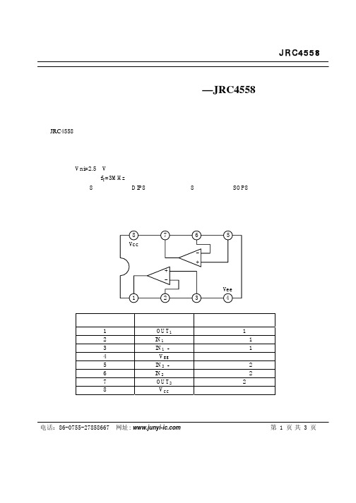
方框图与引出端功能
8 Vcc 7 6 + + 1 2 3 Vee 4 5
引出端序号 1 2 3 4 5 6 7 8
符号 OUT1 IN1(—) IN1(+) VEE IN2(+) IN2(—) OUT2 VCC
功能 输出端 1 反向输入端 1 正向输入端 1 负电源 正向输入端 2 反向输入端 2 输出端 2 正电源
JRC4558
低噪声双运放电路—JRC4558
概述与特点
JRC4558 是低噪声双运算放大器集成电路,最适用于作有源滤波器,补偿放大器,音频前置放大器,均 衡放大器以及在电子仪器、仪表中用作各种线路的放大器。 该电路的特点如下: 内含相位补偿回路; 噪声低,Vni=2.5μV; 速度高,频带宽,fT=3MHz; 采用双列直插 8 脚塑料封装(DIP8)和微形的双列 8 脚塑料封装(SOP8) 。
工作环境温度
电特性(除非特别说明外,VCC=15V,VEE =-15V,Tamb=25℃)
参数名称 电源电流 输入失调电流 输入偏置电流 共模输入电压 最大输出电压 最大输出电压 输出短路电流 输出灌电流 开环电压增益 共模抑制比 电源电压抑制比 输入失调电压 输出电压转换速率 截止频率(开环) 等效输入噪声电压 符号 ICC IIO IIB VIC VOM1 VOM2 IOS IOsink AVO KCMR KSVR VIO SR fT VNI Rs=1kΩ, f=30Hz~30kHz AV=1,RL=2kΩ Vo=±10V,RL=2kΩ RS<10kΩ RS<10kΩ 86 70 76.5 RL=10kΩ RL=2kΩ ±12 ±12 ±10 测试条件 最小 典型 4.0 5 25 ±14 ±14 ±13 40 40 100 90 90 0.5 1.0 3.0 2.5 6.0 最大 6.0 200 500 单位 mA nA nA V V V mA mA dB dB dB mV V/μS MHz μV
UPC4558 中文PDF资料

UPC4558替换型号X4558 双极型线性集成电路
第一价值网(IC网络超市)
SIP-8-2.54
UNIT: mm
第一价值网(IC网络超市)
www.ic-jiazhi.com 7
UPC4558替换型号X4558 双极型线性集成电路
附:
第一价值网(IC网络超市)
典型工作参数曲线(接上表)
第一价值网(IC网络超市)
图 7 图图图图图图图图图图图图图图图
15.0
±15V
13.0
11.0
±12V
图 8 图图图图图图图图图图图图图图图
15.0
±15V
13.0
11.0
±12V
Output Voltage (peak) (V)
Output Voltage (peak) (V)
(仅一个通道)
符号
Vcc VI(DIFF)
VI TOPR TSTG
OUTPUT
输输 1 1 输输 1(-) 2 输输 1(+) 3
Vee 4
8 Vcc
7 输输 2 6 输输 2(-) 5 输输 2(+)
数值
±22 ±18 ±15 0—+70 -65—+150
单位
V V V ℃ ℃
第一价值网(IC网络超市)
3.5 2 5 30 ±12 3.5 20 ±14 ±13 70 76
5.6 6 200 500 ±13 5.6 200
mA mV nA nA V mA V/mV V
90
dB
90
dB
第一价值网(IC网络超市)
www.ic-jiazhi.com 3
双通用运算放大器[NE4558]应用资料
![双通用运算放大器[NE4558]应用资料](https://img.taocdn.com/s3/m/36a45e0a79563c1ec5da7125.png)
DESCRIPTION 8-Pin Plastic Small Outline (SO) Package 8-Pin Plastic Dual In-Line Package (DIP) 8-Pin Plastic Dual In-Line Package (DIP) 8-Pin Plastic Dual In-Line Package (DIP) 8-Pin Plastic Dual In-Line Package (DIP)
Dual general-purpose operational amplifier
NE/SA/SE4558
ABSOLUTE MAXIMUM RATINGS
SYMBOL VCC Supply voltage SE4558 NE4558, SA4558 PD MAX Maximum power dissipation, TA=25°C (Still air)1 N package D package Differential input voltage VIN TSTG TA Input voltage2 Storage temperature range Operating ambient temperature range SE4558 SA4558 NE4558 TSOLD Lead soldering temperature (10sec max) Output short-circuit duration3 -55 to +125 -40 to +85 0 to +70 300 Indefinite °C °C °C °C 1160 780 ±30 ±15 -65 to +150 mW mW V V °C ±22 ±18 V V PARAMETER RATING UNIT
4558工作原理及应用

工作原理,如图纸所示:主要分为三部分。
分别为电源电路、卫星箱功放电路、超重低音电路.一、电源电路(图纸的最下面部分):220V市电经过保险管(F),和开关S后进入变压器初级,变压器的次级输出双12V交流,双12V送入由VD1组成的桥式整流电路电路,经过桥式整流和C14,C15(3300 UF/25V)的滤波后,输出的空载电压约为正负16V左右(根号2乘于12V),即A+为正16V,A-为负16V。
正负16 V为三块功放芯片TDA2030,UTC2030提供电源。
另一路经过R21、R22的降压后,由B+,B-输出约正负12V为低音前置放大和低通滤波器IC4提供电源电压。
在本图纸当中,前置放大的供电并没有采用78/7912三端稳压电路,磨机爱好者在更换两个3300 UF电容时,也可以考虑加入LM7812/7912为前置提供更为稳定的工作电压。
二、左右声道放大电路(卫星箱功放电路),因左右声道作原理完全一致。
这里我只以图纸的左声道为例,作个介绍。
如图:RIN为信号输入端,经过耦合电容C23进入音量电位器,(音量电位器由三个引脚,与C 23连接的是输入端,输出端也叫滑动端、另一引脚为接地端),调整音量后信号进入由R1/C3组成的高音提升电路,此电路可以提升一定量的高频信号,使声音更加清晰。
尔后信号经过耦合电容C1进入左声道功放,型号为UTC2030的1脚,经过功率放大后,由2030的第四脚输出,推动卫星箱发声。
图中的R7为反馈电阻,R7/R9为决定2030芯片的放大倍数。
因此,调整R7的阻值,就可以调整放大倍数。
R11/C7为扬声器补偿网络。
三、超低音电路。
由左右声道经两个10K电阻R5、R6后至C11耦合电容,尔后信号进入IC4,型号为JRC4558的3脚,图中IC4A为超低音的前置放大器。
R201T将此放大器的放大倍数设置为6倍左右。
(R17/R18),经过前置放大后,才能保证足够大的驱动电压,获得足够大的音量。
4558 运算放大器
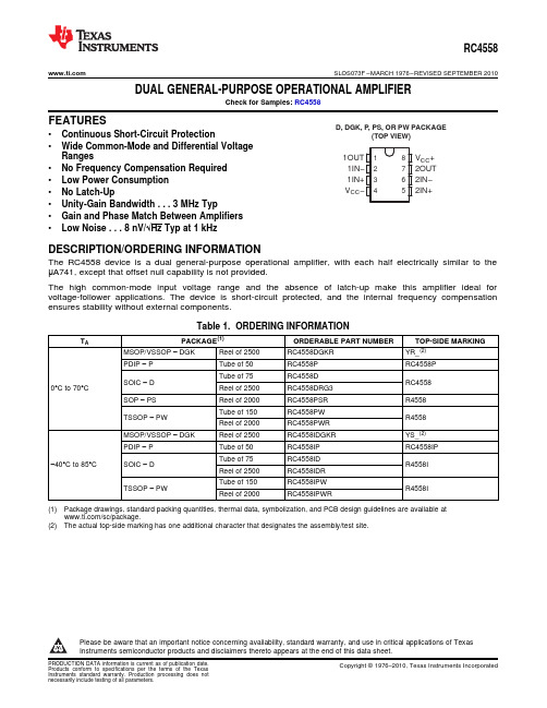
1 2 3 48 7 6 51OUT 1IN−1IN+ V CC−V CC+ 2OUT 2IN−2IN+D, DGK, P, PS, OR PW PACKAGE(TOP VIEW)RC4558 SLOS073F–MARCH1976–REVISED SEPTEMBER2010 DUAL GENERAL-PURPOSE OPERATIONAL AMPLIFIERCheck for Samples:RC4558FEATURES•Continuous Short-Circuit Protection•Wide Common-Mode and Differential VoltageRanges•No Frequency Compensation Required•Low Power Consumption•No Latch-Up•Unity-Gain Bandwidth...3MHz Typ•Gain and Phase Match Between Amplifiers•Low Noise...8nV/√Typ at1kHzDESCRIPTION/ORDERING INFORMATIONThe RC4558device is a dual general-purpose operational amplifier,with each half electrically similar to the μA741,except that offset null capability is not provided.The high common-mode input voltage range and the absence of latch-up make this amplifier ideal for voltage-follower applications.The device is short-circuit protected,and the internal frequency compensation ensures stability without external components.Table1.ORDERING INFORMATIONT A PACKAGE(1)ORDERABLE PART NUMBER TOP-SIDE MARKING MSOP/VSSOP–DGK Reel of2500RC4558DGKR YR_(2)PDIP–P Tube of50RC4558P RC4558PTube of75RC4558DSOIC–D RC45580°C to70°C Reel of2500RC4558DRG3SOP–PS Reel of2000RC4558PSR R4558Tube of150RC4558PWTSSOP–PW R4558Reel of2000RC4558PWRMSOP/VSSOP–DGK Reel of2500RC4558IDGKR YS_(2)PDIP–P Tube of50RC4558IP RC4558IPTube of75RC4558ID–40°C to85°C SOIC–D R4558IReel of2500RC4558IDRTube of150RC4558IPWTSSOP–PW R4558IReel of2000RC4558IPWR(1)Package drawings,standard packing quantities,thermal data,symbolization,and PCB design guidelines are available at/sc/package.(2)The actual top-side marking has one additional character that designates the assembly/test site.Please be aware that an important notice concerning availability,standard warranty,and use in critical applications of TexasInstruments semiconductor products and disclaimers thereto appears at the end of this data sheet.OUTRC4558SLOS073F –MARCH 1976–REVISED SEPTEMBER 2010SCHEMATIC (EACH AMPLIFIER)RC4558 SLOS073F–MARCH1976–REVISED SEPTEMBER2010Absolute Maximum Ratings(1)over operating free-air temperature range(unless otherwise noted)MIN MAX UNITV CC+18 Supply voltage(2)VV CC––18V ID Differential input voltage(3)±30VV I Input voltage(any input)(2)(4)±15V Duration of output short circuit to ground,one amplifier at a time(5)UnlimitedD package97DGK package172θJA Package thermal impedance(6)(7)P package85°C/WPS package95PW package149T J Operating virtual junction temperature150°CT stg Storage temperature range–65150°C (1)Stresses beyond those listed under Absolute Maximum Ratings may cause permanent damage to the device.These are stress ratingsonly,and functional operation of the device at these or any other conditions beyond those indicated under Recommended Operating Conditions is not implied.Exposure to absolute-maximum-rated conditions for extended periods may affect device reliability.(2)All voltage values,unless otherwise noted,are with respect to the midpoint between V CC+and V CC–.(3)Differential voltages are at IN+with respect to IN–.(4)The magnitude of the input voltage must never exceed the magnitude of the supply voltage or15V,whichever is less.(5)Temperature and/or supply voltages must be limited to ensure that the dissipation rating is not exceeded.(6)Maximum power dissipation is a function of T J(max),θJA,and T A.The maximum allowable power dissipation at any allowable ambienttemperature is P D=(T J(max)–T A)/θJA.Operating at the absolute maximum T J of150°C can affect reliability.(7)The package thermal impedance is calculated in accordance with JESD51-7.Recommended Operating ConditionsMIN MAX UNIT V CC+515 Supply voltage VV CC––5–15RC4558070T A Operating free-air temperature°CRC4558I–4085RC4558SLOS073F–MARCH1976–REVISED Electrical Characteristicsat specified free-air temperature,V CC+=15V,V CC–=–15VTESTPARAMETER T A(2)MIN TYP MAX UNITCONDITIONS(1)25°C0.56V IO Input offset voltage V O=0mVFull range7.525°C5200I IO Input offset current V O=0nAFull range30025°C150500I IB Input bias current V O=0nAFull range800V ICR Common-mode input voltage range25°C±12±14VR L=10kΩ25°C±12±14V OM Maximum output voltage swing25°C±10±13VR L=2kΩFull range±1025°C20300R L≥2kΩ,A VD Large-signal differential voltage amplification V/mVV O=±10V Full range15B1Unity-gain bandwith25°C3MHzr i Input resistance25°C0.35MΩCMRR Common-mode rejection ratio25°C7090dBV CC=±15Vk SVS Supply-voltage sensitivity(ΔV IO/ΔV CC)25°C30150μV/Vto±9VA VD=100,R S=100Ω,V n Equivalent input noise voltage(closed loop)25°C8nV/√Hzf=1kHz,BW=1Hz25°C 2.5 5.6V O=0,I CC Supply current(both amplifiers)T A min3 6.6mANo loadT A max 2.3525°C75170V O=0,P D Total power dissipation(both amplifiers)T A min90200mWNo loadT A max70150Open loop85R S=1kΩ,V O1/V O2Crosstalk attenuation25°C dBf=10kHzA VD=100105(1)All characteristics are measured under open-loop conditions with zero common-mode input voltage,unless otherwise specified.(2)Full range is0°C to70°C for RC4558and–40°C to85°C for RC4558I.Operating CharacteristicsV CC+=15V,V CC–=–15V,T A=25°CPARAMETER TEST CONDITIONS MIN TYP MAX UNIT t r Rise time V I=20mV,R L=2kΩ,C L=100pF0.13ns Overshoot V I=20mV,R L=2kΩ,C L=100pF5% SR Slew rate at unity gain V I=10V,R L=2kΩ,C L=100pF 1.1 1.7V/μsRC4558SLOS073F –MARCH 1976–REVISED SEPTEMBER 2010TYPICAL CHARACTERISTICSSUPPLY CURRENTSUPPLY CURRENTvsvsSUPPLY VOLTAGETEMPERATURE (T A =25°C)(V CC =±15V)GAIN AND PHASEGAIN AND PHASEvsvsFREQUENCYFREQUENCY(V CC =±15V,R L =2k Ω,C L =22pF)(V CC =±15V,R L =10k Ω,C L =22pF)RC4558SLOS073F–MARCH1976–REVISED TYPICAL CHARACTERISTICS(continued)OUTPUT VOLTAGE SWING OUTPUT VOLTAGE SWINGvs vsSUPPLY VOLTAGE FREQUENCY(R L=2kΩ,T A=25°C)(V CC=±15V,R L=2kΩ,T A=25°C)OUTPUT VOLTAGE SWING OUTPUT VOLTAGE SWINGvs vsLOAD RESISTANCE TEMPERATURE(V CC=±15V,T A=25°C)(V CC=±15V,R L=10kΩ)RC4558SLOS073F –MARCH 1976–REVISED SEPTEMBER 2010TYPICAL CHARACTERISTICS (continued)NEGATIVE OUTPUT VOLTAGE SWINGOPEN LOOP GAINvsvsTEMPERATUREFREQUENCY(V CC =±15V,R L =10k Ω)(V CC =±15V,R L =2k Ω,C L =22pF,T A =25°C)INPUT BIAS CURRENTINPUT OFFSET VOLTAGEvsvsTEMPERATURE TEMPERATURE (V CC =±15V)(V CC =±15V)RC4558SLOS073F–MARCH1976–REVISED TYPICAL CHARACTERISTICS(continued)INPUT NOISE VOLTAGEvsFREQUENCY(V CC=±15V,T A=25°C)PACKAGING INFORMATIONOrderable Device Status (1)Package Type PackageDrawing Pins Package Qty Eco Plan (2)Lead/Ball FinishMSL Peak Temp (3)Samples(Requires Login)RC4558D ACTIVE SOIC D875Green (RoHS& no Sb/Br)CU NIPDAU Level-1-260C-UNLIM Purchase SamplesRC4558DE4ACTIVE SOIC D875Green (RoHS& no Sb/Br)CU NIPDAU Level-1-260C-UNLIM Purchase SamplesRC4558DG4ACTIVE SOIC D875Green (RoHS& no Sb/Br)CU NIPDAU Level-1-260C-UNLIM Purchase SamplesRC4558DGKR ACTIVE MSOP DGK82500Green (RoHS& no Sb/Br)CU NIPDAU Level-1-260C-UNLIM Contact TI Distributoror Sales OfficeRC4558DGKRG4ACTIVE MSOP DGK82500Green (RoHS& no Sb/Br)CU NIPDAU Level-1-260C-UNLIM Contact TI Distributoror Sales OfficeRC4558DR ACTIVE SOIC D82500Green (RoHS& no Sb/Br)CU NIPDAU Level-1-260C-UNLIM Contact TI Distributoror Sales OfficeRC4558DRE4ACTIVE SOIC D82500Green (RoHS& no Sb/Br)CU NIPDAU Level-1-260C-UNLIM Purchase SamplesRC4558DRG3ACTIVE SOIC D82500Green (RoHS& no Sb/Br)CU SN Level-1-260C-UNLIM Request Free SamplesRC4558DRG4ACTIVE SOIC D82500Green (RoHS& no Sb/Br)CU NIPDAU Level-1-260C-UNLIM Purchase SamplesRC4558ID ACTIVE SOIC D875Green (RoHS& no Sb/Br)CU NIPDAU Level-1-260C-UNLIM Purchase SamplesRC4558IDE4ACTIVE SOIC D875Green (RoHS& no Sb/Br)CU NIPDAU Level-1-260C-UNLIM Purchase SamplesRC4558IDG4ACTIVE SOIC D875Green (RoHS& no Sb/Br)CU NIPDAU Level-1-260C-UNLIM Purchase SamplesRC4558IDGKR ACTIVE MSOP DGK82500Green (RoHS& no Sb/Br)CU NIPDAU Level-1-260C-UNLIM Contact TI Distributoror Sales OfficeRC4558IDGKRG4ACTIVE MSOP DGK82500Green (RoHS& no Sb/Br)CU NIPDAU Level-1-260C-UNLIM Contact TI Distributoror Sales OfficeRC4558IDR ACTIVE SOIC D82500Green (RoHS& no Sb/Br)CU NIPDAU Level-1-260C-UNLIM Contact TI Distributoror Sales OfficeRC4558IDRE4ACTIVE SOIC D82500Green (RoHS& no Sb/Br)CU NIPDAU Level-1-260C-UNLIM Contact TI Distributoror Sales OfficeRC4558IDRG4ACTIVE SOIC D82500Green (RoHS& no Sb/Br)CU NIPDAU Level-1-260C-UNLIM Contact TI Distributoror Sales OfficeAddendum-Page 1Orderable Device Status (1)Package Type PackageDrawing Pins Package Qty Eco Plan (2)Lead/Ball FinishMSL Peak Temp (3)Samples(Requires Login)RC4558IP ACTIVE PDIP P850Pb-Free (RoHS)CU NIPDAU N / A for Pkg Type Contact TI Distributoror Sales Office RC4558IPE4ACTIVE PDIP P850Pb-Free (RoHS)CU NIPDAU N / A for Pkg Type Contact TI Distributoror Sales Office RC4558IPW ACTIVE TSSOP PW8150Green (RoHS& no Sb/Br)CU NIPDAU Level-1-260C-UNLIM Purchase SamplesRC4558IPWE4ACTIVE TSSOP PW8150Green (RoHS& no Sb/Br)CU NIPDAU Level-1-260C-UNLIM Purchase SamplesRC4558IPWG4ACTIVE TSSOP PW8150Green (RoHS& no Sb/Br)CU NIPDAU Level-1-260C-UNLIM Purchase SamplesRC4558IPWR ACTIVE TSSOP PW82000Green (RoHS& no Sb/Br)CU NIPDAU Level-1-260C-UNLIM Contact TI Distributoror Sales OfficeRC4558IPWRE4ACTIVE TSSOP PW82000Green (RoHS& no Sb/Br)CU NIPDAU Level-1-260C-UNLIM Contact TI Distributoror Sales OfficeRC4558IPWRG4ACTIVE TSSOP PW82000Green (RoHS& no Sb/Br)CU NIPDAU Level-1-260C-UNLIM Contact TI Distributoror Sales OfficeRC4558P ACTIVE PDIP P850Pb-Free (RoHS)CU NIPDAU N / A for Pkg Type Contact TI Distributoror Sales Office RC4558PE4ACTIVE PDIP P850Pb-Free (RoHS)CU NIPDAU N / A for Pkg Type Contact TI Distributoror Sales Office RC4558PSLE OBSOLETE SO PS8TBD Call TI Call TI Samples Not AvailableRC4558PSR ACTIVE SO PS82000Green (RoHS& no Sb/Br)CU NIPDAU Level-1-260C-UNLIM Contact TI Distributoror Sales OfficeRC4558PSRE4ACTIVE SO PS82000Green (RoHS& no Sb/Br)CU NIPDAU Level-1-260C-UNLIM Contact TI Distributoror Sales OfficeRC4558PSRG4ACTIVE SO PS82000Green (RoHS& no Sb/Br)CU NIPDAU Level-1-260C-UNLIM Contact TI Distributoror Sales OfficeRC4558PW ACTIVE TSSOP PW8150Green (RoHS& no Sb/Br)CU NIPDAU Level-1-260C-UNLIM Purchase SamplesRC4558PWE4ACTIVE TSSOP PW8150Green (RoHS& no Sb/Br)CU NIPDAU Level-1-260C-UNLIM Purchase SamplesRC4558PWG4ACTIVE TSSOP PW8150Green (RoHS& no Sb/Br)CU NIPDAU Level-1-260C-UNLIM Purchase Samples RC4558PWLE OBSOLETE TSSOP PW8TBD Call TI Call TI Samples Not AvailableRC4558PWR ACTIVE TSSOP PW82000Green (RoHS& no Sb/Br)CU NIPDAU Level-1-260C-UNLIM Contact TI Distributoror Sales OfficeAddendum-Page 2PACKAGE OPTION ADDENDUM 6-Dec-2010Addendum-Page 3Orderable DeviceStatus (1)Package Type Package Drawing Pins Package Qty Eco Plan (2)Lead/Ball Finish MSL Peak Temp (3)Samples (Requires Login)RC4558PWRE4ACTIVE TSSOP PW 82000Green (RoHS & no Sb/Br)CU NIPDAU Level-1-260C-UNLIM Contact TI Distributor or Sales Office RC4558PWRG4ACTIVE TSSOP PW 82000Green (RoHS & no Sb/Br)CU NIPDAU Level-1-260C-UNLIM Contact TI Distributor or Sales Office RC4558YOBSOLETE DIESALE Y 0TBD Call TI Call TI Samples Not Available (1) The marketing status values are defined as follows:ACTIVE: Product device recommended for new designs.LIFEBUY: TI has announced that the device will be discontinued, and a lifetime-buy period is in effect.NRND: Not recommended for new designs. Device is in production to support existing customers, but TI does not recommend using this part in a new design.PREVIEW: Device has been announced but is not in production. Samples may or may not be available.OBSOLETE: TI has discontinued the production of the device.(2) Eco Plan - The planned eco-friendly classification: Pb-Free (RoHS), Pb-Free (RoHS Exempt), or Green (RoHS & no Sb/Br) - please check /productcontent for the latest availability information and additional product content details.TBD: The Pb-Free/Green conversion plan has not been defined.Pb-Free (RoHS): TI's terms "Lead-Free" or "Pb-Free" mean semiconductor products that are compatible with the current RoHS requirements for all 6 substances, including the requirement that lead not exceed 0.1% by weight in homogeneous materials. Where designed to be soldered at high temperatures, TI Pb-Free products are suitable for use in specified lead-free processes.Pb-Free (RoHS Exempt): This component has a RoHS exemption for either 1) lead-based flip-chip solder bumps used between the die and package, or 2) lead-based die adhesive used between the die and leadframe. The component is otherwise considered Pb-Free (RoHS compatible) as defined above.Green (RoHS & no Sb/Br): TI defines "Green" to mean Pb-Free (RoHS compatible), and free of Bromine (Br) and Antimony (Sb) based flame retardants (Br or Sb do not exceed 0.1% by weight in homogeneous material)(3) MSL, Peak Temp. -- The Moisture Sensitivity Level rating according to the JEDEC industry standard classifications, and peak solder temperature.Important Information and Disclaimer:The information provided on this page represents TI's knowledge and belief as of the date that it is provided. TI bases its knowledge and belief on information provided by third parties, and makes no representation or warranty as to the accuracy of such information. Efforts are underway to better integrate information from third parties. TI has taken and continues to take reasonable steps to provide representative and accurate information but may not have conducted destructive testing or chemical analysis on incoming materials and chemicals.TI and TI suppliers consider certain information to be proprietary, and thus CAS numbers and other limited information may not be available for release.In no event shall TI's liability arising out of such information exceed the total purchase price of the TI part(s) at issue in this document sold by TI to Customer on an annual basis.TAPE AND REELINFORMATION *All dimensionsare nominal Device Package Type Package DrawingPinsSPQ Reel Diameter (mm)Reel Width W1(mm)A0(mm)B0(mm)K0(mm)P1(mm)W (mm)Pin1Quadrant RC4558DGKR MSOPDGK 82500330.012.4 5.3 3.4 1.48.012.0Q1RC4558DRG4SOICD 82500330.012.4 6.4 5.2 2.18.012.0Q1RC4558IDGKR MSOPDGK 82500330.012.4 5.3 3.4 1.48.012.0Q1RC4558IDR SOICD 82500330.012.4 6.4 5.2 2.18.012.0Q1RC4558IPWR TSSOPPW 82000330.012.47.0 3.6 1.68.012.0Q1RC4558IPWR TSSOPPW 82000330.012.47.0 3.6 1.68.012.0Q1RC4558PSR SOPS 82000330.016.48.2 6.6 2.512.016.0Q1RC4558PWR TSSOPPW 82000330.012.47.0 3.6 1.68.012.0Q1RC4558PWR TSSOP PW 82000330.012.47.0 3.6 6-Jan-2012*Alldimensions are nominal DevicePackage Type Package Drawing Pins SPQ Length (mm)Width (mm)Height (mm)RC4558DGKRMSOP DGK 82500364.0364.027.0RC4558DRG4SOIC D 82500346.0346.029.0RC4558IDGKRMSOP DGK 82500364.0364.027.0RC4558IDRSOIC D 82500340.5338.120.6RC4558IPWRTSSOP PW 82000364.0364.027.0RC4558IPWRTSSOP PW 82000346.0346.029.0RC4558PSRSO PS 82000346.0346.033.0RC4558PWRTSSOP PW 82000364.0364.027.0RC4558PWR TSSOP PW 82000346.0346.029.0 6-Jan-2012IMPORTANT NOTICETexas Instruments Incorporated and its subsidiaries(TI)reserve the right to make corrections,modifications,enhancements,improvements, and other changes to its products and services at any time and to discontinue any product or service without notice.Customers should obtain the latest relevant information before placing orders and should verify that such information is current and complete.All products are sold subject to TI’s terms and conditions of sale supplied at the time of order acknowledgment.TI warrants performance of its hardware products to the specifications applicable at the time of sale in accordance with TI’s standard warranty.Testing and other quality control techniques are used to the extent TI deems necessary to support this warranty.Except where mandated by government requirements,testing of all parameters of each product is not necessarily performed.TI assumes no liability for applications assistance or customer product design.Customers are responsible for their products and applications using TI components.To minimize the risks associated with customer products and applications,customers should provide adequate design and operating safeguards.TI does not warrant or represent that any license,either express or implied,is granted under any TI patent right,copyright,mask work right, or other TI intellectual property right relating to any combination,machine,or process in which TI products or services are rmation published by TI regarding third-party products or services does not constitute a license from TI to use such products or services or a warranty or endorsement e of such information may require a license from a third party under the patents or other intellectual property of the third party,or a license from TI under the patents or other intellectual property of TI.Reproduction of TI information in TI data books or data sheets is permissible only if reproduction is without alteration and is accompanied by all associated warranties,conditions,limitations,and notices.Reproduction of this information with alteration is an unfair and deceptive business practice.TI is not responsible or liable for such altered rmation of third parties may be subject to additional restrictions.Resale of TI products or services with statements different from or beyond the parameters stated by TI for that product or service voids all express and any implied warranties for the associated TI product or service and is an unfair and deceptive business practice.TI is not responsible or liable for any such statements.TI products are not authorized for use in safety-critical applications(such as life support)where a failure of the TI product would reasonably be expected to cause severe personal injury or death,unless officers of the parties have executed an agreement specifically governing such use.Buyers represent that they have all necessary expertise in the safety and regulatory ramifications of their applications,and acknowledge and agree that they are solely responsible for all legal,regulatory and safety-related requirements concerning their products and any use of TI products in such safety-critical applications,notwithstanding any applications-related information or support that may be provided by TI.Further,Buyers must fully indemnify TI and its representatives against any damages arising out of the use of TI products in such safety-critical applications.TI products are neither designed nor intended for use in military/aerospace applications or environments unless the TI products are specifically designated by TI as military-grade or"enhanced plastic."Only products designated by TI as military-grade meet military specifications.Buyers acknowledge and agree that any such use of TI products which TI has not designated as military-grade is solely at the Buyer's risk,and that they are solely responsible for compliance with all legal and regulatory requirements in connection with such use. TI products are neither designed nor intended for use in automotive applications or environments unless the specific TI products are designated by TI as compliant with ISO/TS16949requirements.Buyers acknowledge and agree that,if they use any non-designated products in automotive applications,TI will not be responsible for any failure to meet such requirements.Following are URLs where you can obtain information on other Texas Instruments products and application solutions:Products ApplicationsAudio /audio Automotive and Transportation /automotiveAmplifiers Communications and Telecom /communicationsData Converters Computers and Peripherals /computersDLP®Products Consumer Electronics /consumer-appsDSP Energy and Lighting /energyClocks and Timers /clocks Industrial /industrialInterface Medical /medicalLogic Security /securityPower Mgmt Space,Avionics and Defense /space-avionics-defense Microcontrollers Video and Imaging /videoRFID OMAP Mobile Processors /omapWireless Connectivity /wirelessconnectivityTI E2E Community Home Page Mailing Address:Texas Instruments,Post Office Box655303,Dallas,Texas75265Copyright©2012,Texas Instruments Incorporated。
NJM4558 中文PDF资料
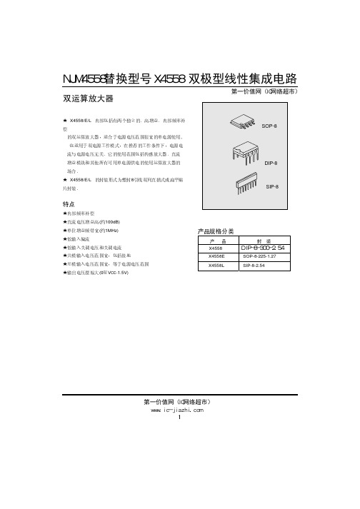
NJM4558替换型号X4558 双极型线性集成电路
第一价值网(IC网络超市)
SIP-8-2.54
UNIT: mm
第一价值网(IC网络超市)
www.ic-jiazhi.com 7
NJM4558替换型号X4558 双极型线性集成电路
附:
第一价值网(IC网络超市)
10 4
频频 频Hz)
10 5
10 6
图 6 PHASE MARGIN vs
FREQUENCY
100 80
60 40
20
0
1
10
100
103
104 105 106
10 7
图图 频Hz)
第一价值网(IC网络超市)
www.ic-jiazhi.com 4
Avd ( dB)
NJM4558替换型号X4558 双极型线性集成电路
典型工作参数曲线(接上表)
第一价值网(IC网络超市)
图 7 图图图图图图图图图图图图图图图
15.0
±15V
13.0
11.0
±12V
图 8 图图图图图图图图图图图图图图图
15.0
±15V
13.0
11.0
±12V
Output Voltage (peak) (V)
Output Voltage (peak) (V)
www.ic-jiazhi.com 8
输入共模电压范围 电源电流 大信号电压增益 输出电压摆幅
共模抑制比 电源电压抑制比
Icc VIO IIO IBIAS VI(R) ICC GV Vo(p-p)
CMRR PSRR
RS<10kΩ
JRC4558中文规格书
双运算放大电路JRC4558 1. 概述与特点
JRC4558 是一块低噪声双运算放大器电路,适用于作有源滤波器、补偿放大器、音频前置放大器、均衡放大器、以及在电子仪器仪表中用作各种线性放大。
其特点如下:
●内含相位补偿回路;
= 2.5uV ;
●噪声低V
NI
●速度高频带宽BW = 3MHz;
●封装形式DIP8 /SOP8;
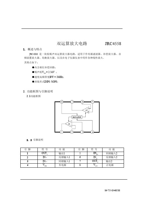
2. 功能框图与引脚说明
2. 1功能框图
2. 2 引脚说明
3. 电特性
3. 1 极限参数
除非另有规定, T amb= 25℃
3. 2 电特性
除非另有规定T
amb = 25℃, V
CC
= +15V , V
EE
= -15V
4. 测试线路
左图开关位置如下
V OM:
S1=BS2断开S3断开情况下的输出电压
S1=AS2断开S3断开情况下的输出电压
S1=BS2接通S3断开情况下的输出电压
S1=AS2断开S3接通情况下的输出电压
Ios,Iosink::
S1=AS2断开S3接通情况下的输入电流
S1=BS2断开S3接通情况下的输出电流
A
VD
=20log(Vo/V)
BW是Vo=V
I 时的V
I
频率(MHz)
C1:隔直流电容
C2:高频旁路电容,云母或钛箔电容5. 特性曲线
6. 应用线路
7. 外形尺寸7. 1 DIP8封装
7. 2 SOP8封装。
奥伟斯科技为您提供AIP4558_AIP4580中微爱芯运算放大器
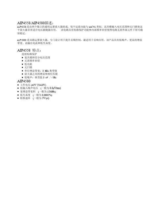
AIP4558/AIP4580描述:AiP4558是由两个独立的通用运算放大器组成。
每个运放功能与uA741类似,高共模输入电压范围和无闩锁使这个放大器非常适合电压跟随器应用。
该电路具有短路保护功能和内部频率补偿使得电路无需外部元件下即可确保稳定。
AiP4580是双路运算放大器,专门设计用于提升音频控制,最适用于音响应用。
该产品具有低噪声、更高的增益带宽、高输出电流和低失真度。
AIP4558 特点:连续短路保护● 宽共模和差分电压范围● 无需频率补偿● 低功耗● 无闩锁●单位增益带宽:3 MHz典型值● 放大器之间的增益和相位匹配● 低噪声:典型值8 nV /√HzAIP4580●工作电压 (±2V到±18V)● 低输入噪声电压(一般为0.8μVrms)● 宽增益带宽积(一般为15MHz)● 低失真度(一般为0.0005%)● 转换速率(一般为5V/μs)1、概述AiP4558是由两个独立的通用运算放大器组成。
每个运放功能与uA741类似,高共模输入电压范围和无闩锁使这个放大器非常适合电压跟随器应用。
该电路具有短路保护功能和内部频率补偿使得电路无需外部元件下即可确保稳定。
其主要特点如下:●连续短路保护●宽共模和差分电压范围●无需频率补偿●低功耗●无闩锁●单位增益带宽:3 MHz典型值●放大器之间的增益和相位匹配●低噪声:典型值8 nV /√Hz●封装形式:SOP8/DIP8/SIP8订购信息:管装:产品型号封装形式打印标识管装数盒装管盒装数箱装盒箱装数备注说明塑封体尺寸:AiP4558SA.TB SOP8 AiP4558100PCS/管100管/盒10000PCS/盒10盒/箱100000PCS/箱4.9mm×3.9mm引脚间距:1.27mm塑封体尺寸:AiP4558DA.TB DIP8 AiP455850PCS/管40管/盒2000PCS/盒10盒/箱20000PCS/箱9.2mm×6.4mm引脚间距:2.54mmAiP4558EA.TB SIP8 AiP455825PCS/管60管/盒1500PCS/盒10盒/箱15000PCS/箱塑封体尺寸:19.2mm×6.5mm引脚间距:2.54mm编带:产品型号封装形式打印标识编带盘装数编带盒装数箱装数备注说明AiP4558SA.TR SOP8(1) AiP4558 4000PCS/盘8000PCS/盒64000PCS/箱塑封体尺寸:4.9mm×3.9mm 引脚间距:1.27mmAiP4558SA.TR SOP8(2) AiP4558 2500PCS/盘5000PCS/盒40000PCS/箱塑封体尺寸:4.9mm×3.9mm 引脚间距:1.27mm注:如实物与订购信息不一致,请以实物为准。
D4558双运算放大器(精)

D4558 双运算放大器
概述:
D4558 内部包括有两个独立的、高增益、内部频率补
偿的双运算放大器,适合于电源电压范围很宽的单电源使用,也适用于双电源工作模式,在推荐的工作条件下,电源电流与电源电压无关。
它的使用范围包括传感放大器、直流增益模块和其他所有可用单电源供电的使用运算放大器的场合。
D4558 采用DIP8 封装形式。
特点:
内部频率补偿
直流电压增益高(约100dB)
单位增益频带宽(约1MHz)
低输入偏流
低输入失调电压和失调电流
共模输入电压范围宽,包括接地
差模输入电压范围宽,等于电源电压范围
输出电压摆幅大(0 至Vcc-1.5V)
内部电路图:
管脚排列图
引出端功能符号:
引出端序号功能符号引出端序号功能符号
1 输出1 OUT 1 5 输入2(+)IN 2(+)
2 输入1(-)IN 1(-) 6 输入2(-)IN 2(-)
3 输入1(+)IN 1(+) 7 输出2 OUT 2
4 Vee Vee 8 电源电压Vcc
极限值(绝对最大额定值,若无其它规定,Tamb=25℃)参数名称符号数值单位
电源电压Vcc ±22 V
差动输入电压V I(DIFF) ±18 V
输入电压V I ±15 V
工作环境温度范围Tamb 0~+70 ℃
贮存温度范围Tstg -65~+150 ℃
电特性(若无其它规定,Tamb=25℃,Vcc=15,Vee=-15V)。
运算放大器4558在麦博音箱里的应用
解密YG4558在麦博音响里的应用
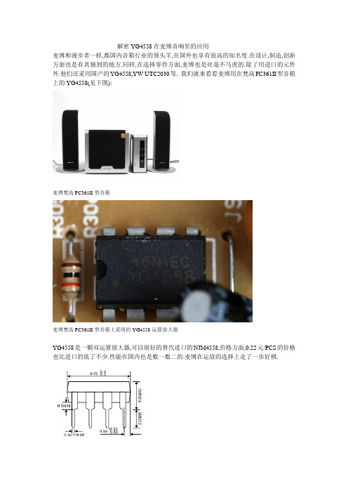
麦博和漫步者一样,都国内音箱行业的领头羊,在国外也享有很高的知名度.在设计,制造,创新方面也是有其独到的地方.同样,在选择零件方面,麦博也是丝毫不马虎的.除了用进口的元件外.他们还采用国产的YG4558,YW-UTC2030等. 我们就来看看麦博用在梵高FC361II型音箱上的YG4558(见下图):
麦博梵高FC361II型音箱
麦博梵高FC361II型音箱上采用的YG4558运算放大器
YG4558是一颗双运算放大器,可以很好的替代进口的NJM4558,价格方面,0.22元/PCS的价格也比进口的低了不少.性能在国内也是数一数二的.麦博在运放的选择上走了一步好棋.
YG4558封装图摘自—。
4558 双运算放大器
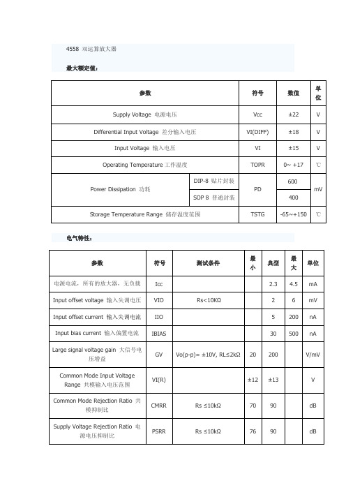
4558 双运算放大器最大额定值:电气特性:Output Voltage swing 输出电压摆幅Vo(p-p) RL≥10kΩ ±12 ±14 V Power Consumption 功耗Pc 70 170 mVSlew Rate 摆率SR Vi=±10V, RL≥2kΩ,CL≤100pF1.22.2 V/μSRise Time 上升时间TRIS Vi=±20mV, RL≥2kΩ,CL≤100pF0.3 μsOvershoot 上过冲OS Vi=±20mV, RL≥2kΩ,CL≤100pF15 %Input Resistance输入电阻Ri 0.3 2 MΩ Output Resistance 输出电阻Ro 75 ΩTotal Harmonic Distortion 总谐波失真THDf=1KHz, Av=20dB,RL=2kΩ, Vo=2Vpp,CL=100pF0.008 %单位增益带宽BW2 2.8MHZ 图1 4558内部电路图图2 4558 单列引脚图图3 4558 双列引脚图4558引脚功能:(双列引脚)1脚通道1输出2脚通道1反相输入3脚通道1同相输入4脚电源负5脚通道2同相输入6脚通道2反相输出7脚通道2输出8脚电源正应用电路:图4 4558 构成的话筒音频放大器图5 4558音频放大图6 4558 用于VCD音频放大电路图7 4558 构成的VCD话筒音频放大器代换型号:M5R4558MC4558NE4558PC4558PSF4558KA4558LM4558TA75559PTDA2320ATDB4558XR4558uA4558RC4558PRC4558DRC4558RC4558DRRC4558PSRRC4558PWR4558RC4558PWRRC4558IDGKRRC4558IPRC4558IDRC4558IDR RC4558IPW R4558IRC4558IPWR。
4558工作原理及应用

工作原理,如图纸所示:主要分为三部分。
分别为电源电路、卫星箱功放电路、超重低音电路.一、电源电路(图纸的最下面部分):220V市电经过保险管(F),和开关S后进入变压器初级,变压器的次级输出双12V交流,双12V送入由VD1组成的桥式整流电路电路,经过桥式整流和C14,C15(3300 UF/25V)的滤波后,输出的空载电压约为正负16V左右(根号2乘于12V),即A+为正16V,A-为负16V。
正负16 V为三块功放芯片TDA2030,UTC2030提供电源。
另一路经过R21、R22的降压后,由B+,B-输出约正负12V为低音前置放大和低通滤波器IC4提供电源电压。
在本图纸当中,前置放大的供电并没有采用78/7912三端稳压电路,磨机爱好者在更换两个3300 UF电容时,也可以考虑加入LM7812/7912为前置提供更为稳定的工作电压。
二、左右声道放大电路(卫星箱功放电路),因左右声道作原理完全一致。
这里我只以图纸的左声道为例,作个介绍。
如图:RIN为信号输入端,经过耦合电容C23进入音量电位器,(音量电位器由三个引脚,与C 23连接的是输入端,输出端也叫滑动端、另一引脚为接地端),调整音量后信号进入由R1/C3组成的高音提升电路,此电路可以提升一定量的高频信号,使声音更加清晰。
尔后信号经过耦合电容C1进入左声道功放,型号为UTC2030的1脚,经过功率放大后,由2030的第四脚输出,推动卫星箱发声。
图中的R7为反馈电阻,R7/R9为决定2030芯片的放大倍数。
因此,调整R7的阻值,就可以调整放大倍数。
R11/C7为扬声器补偿网络。
三、超低音电路。
由左右声道经两个10K电阻R5、R6后至C11耦合电容,尔后信号进入IC4,型号为JRC4558的3脚,图中IC4A为超低音的前置放大器。
R201T将此放大器的放大倍数设置为6倍左右。
(R17/R18),经过前置放大后,才能保证足够大的驱动电压,获得足够大的音量。
CF4558CB CP替代JRC-NJM4558
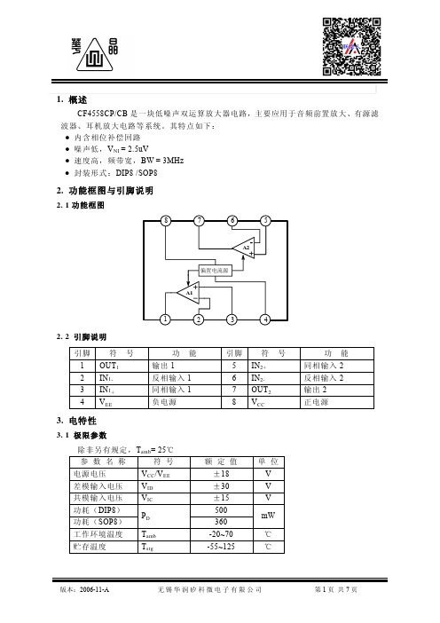
输出电压
转换速率
SR
AV=1, RL=2kΩ
0.5 6 1.0
单位增益带宽 BW 开环,增益为 0dB
3.0
等效输入 噪声电压
VNI
RS=1kΩ f=30Hz~30kHz
2.5
单位
mA nA nA V V V mA mA dB dB
μV/V
mV
V/μS
MHz
μ Vr ms
图号
4.5 4.2 4.2 4.3 4.4 4.4 4.4 4.4 4.7 4.3
4.1
4.1
4.6
4.7
4. 测试线路
Vcc
1MΩ
A
Vo
VEE 图-V4.1
KSVR= (VIO1-VIO2) /5 (μV/V) VIO1: VCC= + 17.5V,VEE= - 17.5V VIO2: VCC= + 12.5V,VEE= - 12.5V
10kΩ 10kΩ
图 4.1
Vcc
IIO
A
VEE 2kΩ
10%
0
图 4.7
AVD=20lg(Vo/VI) BW 是 Vo=VI 时的 VI 频率(MHz) C1:隔直流电容 C2:高频旁路电容,云母或钛箔电容
5. 特性曲线
输入偏置电流I IB(nA)
最大输出电压 VOM(V)
I IB -Tamb 80
Vcc=± 15V 70
60
50 40 30
图 4.3
Vcc
A S1
VEE
AB Vcc/2
S2 S3 -V Vo
Ios、Iosink RL -A
图 4.4
左图开关位置如下: VOM:
4558工作原理及应用

工作原理,如图纸所示:主要分为三部分。
分别为电源电路、卫星箱功放电路、超重低音电路.一、电源电路(图纸的最下面部分):220V市电经过保险管(F),和开关S后进入变压器初级,变压器的次级输出双12V交流,双12V送入由VD1组成的桥式整流电路电路,经过桥式整流和C14,C15(3300 UF/25V)的滤波后,输出的空载电压约为正负16V左右(根号2乘于12V),即A+为正16V,A-为负16V。
正负16 V为三块功放芯片TDA2030,UTC2030提供电源。
另一路经过R21、R22的降压后,由B+,B-输出约正负12V为低音前置放大和低通滤波器IC4提供电源电压。
在本图纸当中,前置放大的供电并没有采用78/7912三端稳压电路,磨机爱好者在更换两个3300 UF电容时,也可以考虑加入LM7812/7912为前置提供更为稳定的工作电压。
二、左右声道放大电路(卫星箱功放电路),因左右声道作原理完全一致。
这里我只以图纸的左声道为例,作个介绍。
如图:RIN为信号输入端,经过耦合电容C23进入音量电位器,(音量电位器由三个引脚,与C 23连接的是输入端,输出端也叫滑动端、另一引脚为接地端),调整音量后信号进入由R1/C3组成的高音提升电路,此电路可以提升一定量的高频信号,使声音更加清晰。
尔后信号经过耦合电容C1进入左声道功放,型号为UTC2030的1脚,经过功率放大后,由2030的第四脚输出,推动卫星箱发声。
图中的R7为反馈电阻,R7/R9为决定2030芯片的放大倍数。
因此,调整R7的阻值,就可以调整放大倍数。
R11/C7为扬声器补偿网络。
三、超低音电路。
由左右声道经两个10K电阻R5、R6后至C11耦合电容,尔后信号进入IC4,型号为JRC4558的3脚,图中IC4A为超低音的前置放大器。
R201T将此放大器的放大倍数设置为6倍左右。
(R17/R18),经过前置放大后,才能保证足够大的驱动电压,获得足够大的音量。
