压缩车使用说明
压缩垃圾车使用说明书

压缩垃圾车使用说明书压缩垃圾车使用说明书1、介绍本使用说明书旨在为用户提供关于压缩垃圾车的详细操作指南,以确保正确、安全地使用该设备。
请您在使用之前仔细阅读本手册,并按照指导进行操作。
2、设备概述- 压缩垃圾车是一种用于收集、储存和压缩垃圾的汽车设备。
- 该设备具备垃圾收集、压缩和运输的功能,旨在提高垃圾处理效率。
3、安全须知- 在操作过程中,请确保穿戴合适的防护装备,如手套、口罩和护目镜。
- 在压缩垃圾车运行时,严禁站在车辆后方或垃圾箱边附近。
- 切勿使用压缩垃圾车处理有爆炸性、易燃性或毒性的物质。
- 在开动或停止压缩垃圾车前,请检查车辆周围环境是否安全。
- 若发现设备故障或异常,请立即停止使用,并联系维修人员进行检修。
4、操作流程4.1 准备工作- 确保垃圾车内垃圾箱已清空,并检查是否存在异物。
- 检查车辆润滑油、燃料和冷却液是否符合要求。
4.2 打开垃圾箱- 打开驾驶室的垃圾箱控制按钮。
- 定位车辆使垃圾箱面朝垃圾集中地点。
- 按下控制按钮,使垃圾箱打开。
4.3 压缩垃圾- 使用压缩垃圾车配备的装载设备将垃圾装入垃圾箱。
- 在装载过程中,确保垃圾平均分布并避免过度压缩。
4.4 关闭垃圾箱- 当垃圾装载完成后,按下控制按钮,使垃圾箱关闭。
4.5 运输垃圾- 验证垃圾箱是否安全关闭并固定。
- 根据相关法律要求将垃圾车驶离现场,并前往垃圾处理中心。
5、维护与保养- 定期检查垃圾车的润滑油、燃料和冷却液,并及时添加或更换。
- 注意清洁垃圾箱,避免异物和杂质堆积。
6、附件本文档涉及附件,请查阅附件文件。
7、法律名词及注释- 垃圾:根据《城市垃圾管理法》中定义,指的是生活、生产、服务等活动产生的废弃物。
- 压缩垃圾车:指用于收集、储存和压缩垃圾的专用车辆。
压缩垃圾车使用说明书
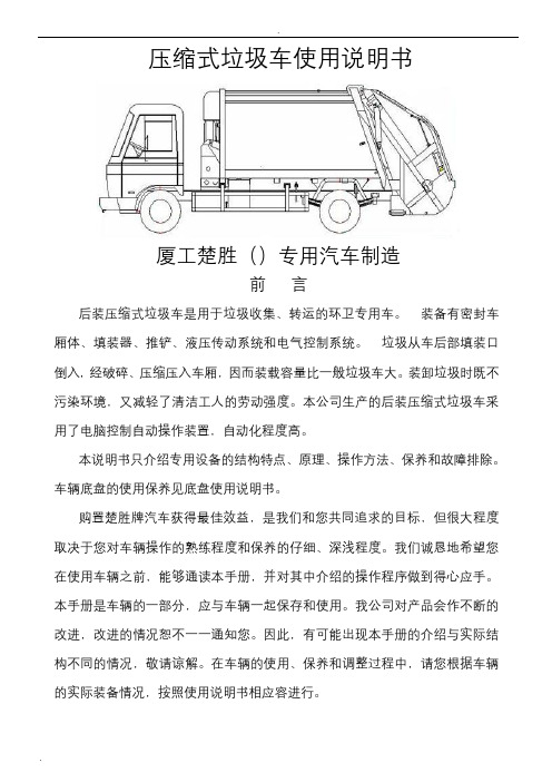
压缩式垃圾车使用说明书厦工楚胜()专用汽车制造前言后装压缩式垃圾车是用于垃圾收集、转运的环卫专用车。
•装备有密封车厢体、填装器、推铲、液压传动系统和电气控制系统。
•垃圾从车后部填装口倒入, 经破碎、压缩压入车厢,因而装载容量比一般垃圾车大。
装卸垃圾时既不污染环境,又减轻了清洁工人的劳动强度。
本公司生产的后装压缩式垃圾车采用了电脑控制自动操作装置,自动化程度高。
本说明书只介绍专用设备的结构特点、原理、操作方法、保养和故障排除。
车辆底盘的使用保养见底盘使用说明书。
购置楚胜牌汽车获得最佳效益,是我们和您共同追求的目标,但很大程度取决于您对车辆操作的熟练程度和保养的仔细、深浅程度。
我们诚恳地希望您在使用车辆之前,能够通读本手册,并对其中介绍的操作程序做到得心应手。
本手册是车辆的一部分,应与车辆一起保存和使用。
我公司对产品会作不断的改进,改进的情况恕不一一通知您。
因此,有可能出现本手册的介绍与实际结构不同的情况,敬请谅解。
在车辆的使用、保养和调整过程中,请您根据车辆的实际装备情况,按照使用说明书相应容进行。
一.概述采用载重质量3~12吨底盘改装生产的CSC5060ZYS~5250ZYS型系列压缩式垃圾车后装压缩型式,是厦工楚胜()专用汽车制造在吸收多种国外同类产品优点的基础上,自主开发、设计的新一代后装压缩式垃圾车。
该车外形美观,性能优良,操纵控制先进,采用后装压缩和双向压缩技术完成对城镇生活垃圾的收集和转运,装载能力强,装载量大,其综合性能达到国同类产品的先进水平。
底盘采用东风、解放等二类汽车底盘,品质优良,发动机功率强劲,排放达到国(欧)Ⅲ和国(欧)Ⅳ标准。
主要适用于城镇居民区、社区、大型厂矿和机关院校的桶装、袋装和散装生活垃圾的收运。
拥有多种翻桶(斗)机构,适用于不同用户的多种垃圾收集方式。
二.垃圾车外形图(以下几种为任选的代表车型)1.东风天锦后装压缩带摆臂(选装)2.东风福瑞卡后装压缩带挂桶(选装铁桶或塑料桶)3.东风天龙垃圾车三.主要技术参数和性能产品型号CSC5070ZYS4 CSC5082ZYS4 CSC5128ZYSE CSC5161ZYSD12 底盘型号DFA1070SJ35D6 DFA1080SJ12D3 EQ1128GLJ DFL1160BX4 货厢容积m3 6 8 10 12尺寸参数长×宽×高mm 6550X2050X2600 7160X2250X26508150X2480X32508850X2490X3220轴距mm 3300 3800 3950 4500轮距前mm 1506 1770 1880 1880后mm 1466 1586 1800 1860*.以上车型的参数只是列举部分,没有的车型参数以公告为准四.压缩式垃圾车的工作原理1. 垃圾压缩填装过程垃圾压缩填装过程见图一,步骤(1),为起始位置,当填装料斗装满垃圾后,刮板打开,作好插入松散垃圾的准备,步骤(2),滑板带动刮板一起向下移动,插入垃圾中进行破碎和首次压缩。
压缩式垃圾车操作方法

压缩式垃圾车操作方法
1.准备工作
(1) 在准备操作前,首先应该检查垃圾车的各个部件是否完好,特别是液压系统是否正常工作。
(2) 准备好垃圾车的工具和备用零件,如液压油,密封圈等。
2.启动垃圾车
(1) 在进入垃圾车驾驶室前,先将门窗打开通风,并检查座椅和安全带是否齐全。
(2) 将钥匙插入点火开关并启动引擎,然后将手刹松开。
(3) 根据需要,选择前进或倒车挡,并加速以便垃圾车能够行动。
3.收集垃圾
(1) 驾驶垃圾车到被清理的区域,然后打开垃圾车上的夹紧装置并把夹把伸出。
(2) 将夹紧装置置于垃圾上方,并将夹把放下以夹住垃圾。
(3) 将夹把缓慢地上升并收回到垃圾车内部,同时将垃圾清了。
4.卸载垃圾
(1) 将垃圾车驶回垃圾站,并将车停靠在卸载区域。
(2) 打开垃圾车尾部的卸载门,并启动发动机,以便液压系统开始运作。
(3) 将夹把缓慢放下,直至垃圾倾倒到卸载区域中。
(4) 清理好卸载区域并关闭卸载门。
5.维护和保养
(1) 操作完毕后,将垃圾车停好,然后关闭发动机。
(2) 清理垃圾车上的残留物,并检查液压系统、电气系统及车身骨架等部件是否损坏或有异常。
(3) 更换液压油和密封圈等零部件,以确保垃圾车的长期使用。
(4) 定期对垃圾车进行维护和保养,保证其性能在最佳状态下运转。
康诺流体 HPNGV2 系列压缩天然气车用调压器使用说明书和维护手册

Enidine / Conoflow105 Commerce Way Westminster, SC 29693Tel: (864) 647-9521 Fax: (864) 647-9574INSTRUCTION AND MAINTENANCE MANUALHPNGV2 Series Compressed Natural GasVehicle RegulatorWARNING: These instructions must be read carefully prior to installation and system startup.INTRODUCTION: The HPNGV Series regulator is a self contained, pressure reducing regulator designed and qualified for 3000 and 3600 psig CNG vehicular fuel systems. This regulator is factory calibrated and is not field adjustable. Various configurations of this regulator are available, based on the application needs. Consult the factory for part numbers, service kits, or configuration assistance.SYSTEM REQUIREMENTS : High pressure CNGfiltration (1 micron rating) is required to keep particulates in the gas stream from damaging the regulator and downstream components. The filter must be located upstream of the pressure regulator. Clean, burr free fittings and lines must be used to prevent particulate damage to the regulator.CONNECTIONS : The HPNGV Series regulator is connected to the fuel system by inlet and outlet ports. These ports use CNG compliant SAE J1926 o-ring boss connections for 3/8” size tubing at the inlet connection (9/16-18 thread) and 1/2” size tubing at the outlet connection (3/4-16 thread). These connections are labeled “INLET” and “OUTLET”. The inlet and outlet lines must be sized for sufficient flow, and the outlet fitting must provide a 3/8” minimum bore for gas flow.A coolant circulation bowl is provided which permits engine heat to warm the regulator and prevent internal icing of the regulator valve. An optional coolantcirculation bowl is available with a thermostat. Both coolant bowls are labeled for coolant inlet and outlet, adjacent to the connections. Standard coolant lineconnections are for 3/8” reinforced rubber hose, which is secured with hose clamps.An optional SAE-3 transducer port is available to allow a high pressure transducer to be directly installed in the regulator to measure inlet pressure.Optional pressure bias controls (manifold pressure reference) are available.A pressure relief device (PRD) is provided. Standard (light duty) configurations discharge directly to atmosphere, while capture pipes are available for enclosed spaces or heavy duty applications.CAUTION: The regulator’s PRD is a control and nota system safety device. It may not protect theregulator or fuel system under all possible / potential failure modes. A downstream safety valve or other failsafe strategy must be used to fully protect the fuel system and vehicle. The PRD port must not be blocked by any obstruction.MOUNTING : Two (2) M8 X 1.25 threaded holes areprovided in the regulator to enable sturdy mounting. The regulator may be oriented in any direction; however Conoflow recommends that the gas ports arehorizontally oriented to minimize exposure of the gas lines, and prevent collection of oil and moisture in the downstream line. The regulator must be rigidly mounted on the vehicle, and protected from impact of road debris.WARNING : Do not mount the regulator by gas or coolant connections only. This regulator must be securely mounted by M8 x 1.25 bolts.Please refer to the interface drawings for mounting dimensions, connection identification and connection details.SPECIFICATIONS:Maximum Operating Inlet Pressure:3600 psig (248 bar)Outlet Pressure: Factory preset – see regulator labelWARNINGConoflow’s products are designed andmanufactured using materials and workmanship required to meet applicable standards. The use of these products should be confined to services specified and/or recommended in the Conoflow catalogs, instructions, or by Conoflow application engineers.To avoid personal injury or equipment damage resulting from misuse or misapplication of a product, it is necessary to select the proper materials of construction and pressure-temperature ratings which are consistent with performance requirements.Outlet Pressure Variation in Service: -10 to +18 psi from labeled setting throughout the range of operating inlet pressure, temperature and gas flow. See flow performance graph to see effect of changes to inlet pressure and gas flow.Temperature Range: -40° F to 250° F(-40 °C to 120 °C) Connection Torques: Inlet (SAE-6): 27 ft-lbOutlet (SAE-8): 42 ft-lbTransducer (SAE-3): 8 ft-lbMounting Bolts: 15 ft-lbFlow Capacity: To 175 lb/hr of CNG. (Flowvaries by application, consultthe factory for data.)PRD Opening: 200 +/- 40 psig (optional)270 +/- 60 psig (standard)350 +/- 60 psig (optional)PRD Type: ReseatableMATERIALS OF CONSTRUCTION:Body: 6061-T6 AluminumBonnet: 6061-T6 Aluminum Diaphragm / Seals: Nitrile Rubber classValve Trim: Stainless Steel / Polyimide /PEEKNOTE: This regulator has been tested and certified for safe and reliable service in Natural Gas Vehicles. There are significant potential hazards associated with CNG which the user and / or installer must be aware of when using this product.CAUTION: Install the regulator in accordance with NFPA 52, CAN/CGA-B149.4 and other codes and standards applicable to the jurisdiction of installation and service.WARNING: CNG can cause damage and / or injury due to very high pressure, flammability, and extreme cold during expansion. Suitable safeguards must be employed during installation, commissioning and service to prevent harm to personnel and property.PRINCIPLE OF OPERATIONThe HPNGV series is a mechanical pressure regulator. The main valve, within the regulator, is coupled to a diaphragm assembly. A spring preload against the diaphragm assembly pushes the main valve open. As gas flows through the regulator, downstream pressure will increase and push the diaphragm assembly against the spring load, closing the main valve. The diaphragm and valve are dynamic, and will seek equilibrium so the inlet pressure is reduced and regulated throughout the useful range of gas flow.When the engine is shut off, gas flow through the regulator ceases. The regulator’s main valve is pulled closed by the diaphragm assembly and downstream pressure will be trapped in the low pressure side of the fuel system.An engine coolant circulation bowl is fitted over the end of the regulator to provide engine heat to the regulator valve and the gas. This heat prevents ice buildup in the regulator, which could reduce performance and regulator life.INSTALLATION GUIDELINES1. Plan the installation for the best combination ofaccessibility, protection from engine exhaustheat, mechanical vibration or impact, andsuitable mounting orientation.SEE SYSTEM IMPERATIVES ON PAGES 3 and 42. A suitable lubricant (oil, synthetic grease, etc)should be applied to the o-ring of the fitting, priorto installation, to help the o-ring seat and seal.Do not use silicon grease – silicon may poisonthe oxygen sensor in some vehicles. Install thefitting in the applicable gas port.3. If the regulator is equipped with an optional PRDcapture pipe, connect the system fitting to thecapture pipe.NOTE: If the optional ¼” NPT PRD CapturePipe is used, it must be wrench supportedduring connection.4. Attach regulator securely to vehicle, using twoM8 x 1.25 mounting bolts (not included).5. Connect the inlet, outlet, and coolantconnections. Assure any entrapped air inregulator is fully purged from coolant bowl. Ifapplicable, connect the PRD and transducer.6. Pressurize the system and perform a leak test ofgas connections with liquid leak detectionsolution or soapy water.SYSTEM IMPERATIVESImperatives are those conditions, when violated, can cause regulator or system failure and an increased risk of gas release. The following imperatives are listed with potential risks to assist the fuel system integrator with system design failure modes and effects analysis.1. Upstream Coalescing FilterAlthough the regulator is equipped with an internal filter, a suitable coalescing filter must be installed immediately upstream of the regulator. This filter should be sized for suitable flow and condensate capacity. The purpose of this filter is to prevent excessive moisture and compressor oil or particulate contaminants from entering the regulator and flowing downstream to the fuel management system.A one (1) micron filter will sufficiently protect the regulator from particulate contamination damage.This filter must be located as close to the regulator as possible to prevent any particulate in the connection between the filter and regulator from accelerating upon system pressurization, and piercing the regulator’s internal filter.2. Upstream Lockoff (solenoid) ValveA normally closed solenoid valve must be installed upstream of the regulator. This is a safety requirement to prevent gas from freely flowing during vehicle shutdown. Although the regulator is capable of bubble tight shutoff, the upstream lockoff valve is the correct safety device for this function.3. SealantsSealants are not required for the SAE o-ring boss connections. The use of sealants as a fitting leakage preventive measure can contaminate the internal passages and valve in the regulator and cause a malfunction. Sealant use in these connections will void the factory warranty.4. Inlet / Outlet LinesTo prevent excessive pressure drop at flow, the inlet and outlet fuel lines should be of suitable size. The regulator has been designed for SAE o-ring boss fittings which correspond to 3/8 inch OD tubing (SAE-6) for the inlet, and 1/2 inch OD tubing (SAE-8) for the outlet. These are the recommended line sizes. Excessively large line or fitting diameters may induce instability of the delivery pressure. The minimum bore of the fittings must be a minimum of 0.27 inch (6.8 mm) for the SAE-6 inlet fitting and 0.37 inch (9.4 mm) for the SAE-8 outlet fitting. Fittings may be of type SAE J1926/2 or SAE J1926/3.Tubing must be clean and free of burrs, which could contaminate the regulator or system. The outlet line should not be run upward from the regulator outlet port, due to the potential for excessive oil and condensate collection. A level or downward run is preferred to prevent collection.5. Downstream Relief ValveAlthough the regulator is equipped with a pressure relief device (PRD), a high flow relief valve or other protective strategy must be installed between the regulator outlet and the remainder of the fuel system. The regulator PRD is not a high flow device and may not protect the regulator or fuel system in case of sudden failure.6. Engine CoolantThe expansion of high pressure gas to low pressure creates a significant temperature drop. To prevent moisture from freezing inside the regulator and creating a blockage, heated engine coolant must be circulated within the regulator. The regulator is equipped with a coolant bowl for this purpose.Engine coolant must be maintained for at least –40 degree antifreeze protection. If the coolant were to freeze in the regulator, for any reason, the coolant containment integrity may be compromised.Suggested minimum flow: Engine idle 1-2 lpm, Moderate power 3-6 lpm, depending on engine size.7. Excessive TemperatureThe regulator is designed for safe and reliable operation within a temperature range of –40 to 250 °F. Temperatures beyond 275 °F can cause permanent damage to internal seals and must be avoided. If the regulator is located in an area with the potential for high temperature (such as radiated energy from exhaust system components, etc), suitable heat shields must be employed.8. Fitting TorqueThe correct assembly torque for the inlet (SAE-6) fitting is 27 ft-lb.The correct assembly torque for the outlet (SAE-8) fitting is 42 ft-lb.The correct assembly torque for the optional transducer port is 8 ft-lb.Inadequate torque could allow the fitting to loosen in service and leak. Excessive torque could weaken or shear the threads in the inlet and / or outlet port of the regulator.The inlet and outlet fitting is sealed with an o-ring.9. Submergence in waterExcept for bonnet bias models, the regulator uses an atmospheric reference hole in the bonnet to sense ambient pressure. This hole is “filled” with a porous hydrophobic plastic plug to prevent water intrusion from splashing, wash down, etc. This plug may not prevent water intrusion if the regulator were to be submerged in water. For this reason, the regulator should not be mounted low in a vehicle which would have to cross flooded roads, etc.10. Chemicals in FuelAny cleaners or abnormal additives, drying agents, etc in the fuel could cause damage to the regulator’s internal seals. The regulator is tolerant to substances that occur in compressed natural gas, including compressor oils, however ITT Conoflow should be contacted regarding other materials.11. Rapid or Frequent Fuel System DecompressionCNG Fuel systems should not be rapidly or frequently decompressed of gas. Doing so will cause high pressure gas absorbed in non metallic materials to attempt to escape those materials, increasing the speed of component degradation.12. Salt and/or Dirt BuildupExcessive road salt and/or road dirt buildup will accelerate moisture attack and subsequent corrosion of the regulator at the solenoid and/or gas connections. Accelerated corrosion leads to premature external gas leakage failure.The regulator must be installed in a manner which provides reasonable protection from road salt and debris accumulation, to reduce the risks of accelerated corrosion.13. Pressure AdjustmentThis pressure regulator is factory calibrated and tested. Removing the tamper evident cover from the adjustment will void the warranty.14. Fuel System ValidationThis fuel pressure regulator will dynamically respond to the CNG fuel system. In new applications it is the responsibility of the customer to validate the performance of the fuel system with this regulator. ITT cannot be responsible for the suitability of this fuel pressure regulator in every application.15. Fuel Type / Quality This fuel pressure regulator is designed and qualified for CNG fuel. RNG (Renewable Natural Gas) is acceptable, provided it meets the quality guidelines of the American Biogas Council (ABC) for CNG fuel. This fuel pressure regulator is not for use with raw biogas.As part of your fuel system and vehicle protection review, ITT recommends the incorporation of a system warning label that clearly advises maintenance technicians to 1) NOT DISABLE any automatic upstream isolation valves and to 2) CLOSE upstream isolation valves, whenever feasible during servicing.WARNING: Bleed system pressure prior to servicing or removal of the pressure regulator from the fuel system.CAUTION: Stored spring compression within the regulator can be unexpectedly released if the regulator is disassembled incorrectlyTROUBLESHOOTING:1. The regulator “pops” when I turn on ignition keyand activate tank solenoid valve(s).This is caused by downstream leakage, orintentional fuel system decompression. If thedownstream pressure bleeds down, the inrush ofhigh pressure CNG can cause the regulatoroutlet pressure to overshoot the PRD openingpressure and discharge excessive pressure fromthe line. Correct / repair any downstreamleakage to prevent system depressurizationwhen the vehicle is not operating.2. After driving the vehicle, I see frost on theexterior of the regulator and outlet fuel line.This is quite common for driving cycles wherethere is a significant amount of gas flow.Although the regulator is heated with enginecoolant, this heat is used to protect the valve,and is not sufficient to heat the fuel completely.As the fuel flows to the engine, it will pick upheat from the fuel line. Some heavy dutyapplications may require a downstream heatexchanger.3. When leak testing the system, our gas detectorshows leakage from the white plug on theregulator.A very slight amount of gas permeates from theregulator, and this is normal. A gas detector can show leakage “false alarms”, as this instrumentis very sensitive. Conoflow recommends usingcommercially available leak detection solution,or soapy water, to leak test the system.4. Loud noises are coming from the regulator.Noisy operation can be caused by a number ofsystem related issues. If incorrectfittings or line sizes are used (small bore fittings, tubing too small), the regulator may be starvedfor pressure and overshoot the steadyequilibrium it is trying to achieve. This will cause internal oscillation which can create noisesranging from a buzzing sound to a rapid internal knocking sound.In rare instances, the regulator’s resonantfrequency (typically around 380 Hz) will matchthe fuel system’s resonant frequency. Simplychanging the length of the outlet line will usuallysolve this issue.MAINTENANCEProperly designed and maintained fuel systems will increase the reliability and life of this pressure regulator.1. Follow vehicle guidelines for fuel system filter maintenance and engine coolant maintenance.2. Keep the exterior of the regulator clean to reduce buildup. Dirt or salt buildup can attract moisture and accelerate corrosion. Protective sprays may be used in areas where dissimilar metals (gas connections, etc) meet.3. Schedule leak testing to verify regulator gas containment. Leakage is the result of wear and aging; it is the inevitable failure mode of the pressure regulator.Regulator Model Breakdown (CED Code)1 through 6 HPNGV2 Regulator Base Model7 S Standard BonnetC 3/16” Straight Hose Barb Connection on BonnetE 1/4” Tube Elbow (for Poly Tubing) Connection on Bonnet8 X No Sensor Port3 SAE-3 Sensor Port4 SAE-4 Sensor PortW Sensor (Installed) 0.25 to 4.75 Volt OutputY Sensor (Installed) 0.50 to 4.50 Volt Output9 T Integral Coolant Hose ConnectionsH Brass Coolant Hose Connections10 A 200 psi (+/- 40) PRD SettingB 270 psi (+/- 60) PRD SettingC 350 psi (+/- 60) PRD Setting11 X PRD Discharges to atmosphereP 1/4” Male NPT PRD Capture PipeT 1/2” Tube Stub PRD Capture Pipe12 through 14 XXX Output Pressure Setting (PSI)CAUTION: Regulator is factory preset. Changing the pressure setting can cause unexpected and/or potentially hazardous operation. Removal of the tamperproof cover will void the warranty.CONNECTION IDENTIFICATION AND TYPICAL GEOMETRY HPNGV2S3T_X___ CONFIGURATION SHOWN – DIMENSIONS IN MILLIMETER (INCH)Interface Views – OptionsELECTRICAL INTERFACE DATAOEM pressure sensor electrical mating connector part numbers:Housing: Delphi 12065287 (with included weather seal)Contacts: Delphi 12110236Suggested wire gauge: 18 gaugeWARNING: Circuit protection with a 1A maximum current is required for sensor power lead wiring.The components above may be substituted for functional equivalents. Other contacts and seals are available for alternative wire sizes. Consult OEM connector supplier data.When selecting alternatives, the following guidelines must be considered:• Mating terminals must be tin-plated. Gold-plated connectors may cause galvanic corrosion of the connection interface and ultimately prevent the pressure sensor from operating.• Weather seals must be used between the connector bodies, and at the cable ports.Sensor polarity / pin connection diagram:Vpwr = 5.0 +/- 0.25 VDCVout = Ratiometric output (product dependent)Ground = Common ground。
电动压缩机说明书(电动汽车用)

BYC(H)312-1000-2变频电机控制器规格书1.技术性能指标
3.命名规则
BYC- XX- X XX X -X
①②③④
①博阳控制器;
②额定最大电压域,单位V;
③额定功率域,单位W;
④电机极对数。
4、安装说明
控制器安装在通风良好,无雨水直接滴淋并且基座坚固的位置,底板通过导热硅脂固定在可散热的金属平面上,保证良好散热。
安装前请清理安装基板,并确认基座平整,无水、油、灰尘!
详细安装尺寸及接线方式见控制器接线图
5.操作说明
◆调速模式:
①、按接线说明,连接好电源线、电机线及各信号线。
②、确认接线无误后,接通电源,过两秒左右控制器指示灯常亮,等待45秒后,电机会逐渐加速至设定速度。
6.常见故障及处理方法。
垃圾压缩站对接式垃圾车使用说明书
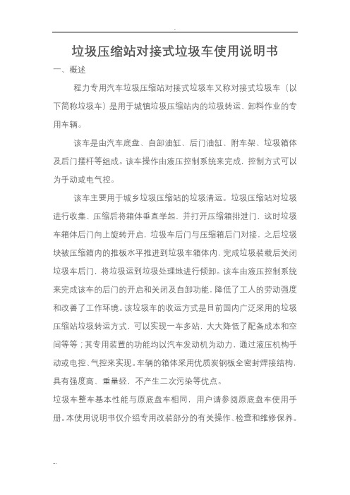
垃圾压缩站对接式垃圾车使用说明书一、概述程力专用汽车垃圾压缩站对接式垃圾车又称对接式垃圾车(以下简称垃圾车)是用于城镇垃圾压缩站内的垃圾转运、卸料作业的专用车辆。
该车是由汽车底盘、自卸油缸、后门油缸、附车架、垃圾箱体及后门摆杆等组成。
该车操作由液压控制系统来完成,控制方式可以为手动或电气控。
该车主要用于城乡垃圾压缩站的垃圾清运。
垃圾压缩站对垃圾进行收集、压缩后将箱体垂直举起,并打开压缩箱排泄门,这时垃圾车箱体后门向上旋转开启,垃圾车后门与压缩箱后门对接,之后垃圾块被压缩箱内的推板水平推进到垃圾车箱体内,完成垃圾装载后关闭垃圾车后门,将垃圾运到垃圾处理地进行倾卸。
该车由液压控制系统来完成该车的后门的开启和关闭及自卸功能,降低了工人的劳动强度和改善了工作环境。
该垃圾车的收运方式是目前国内广泛采用的垃圾压缩站垃圾转运方式,可以实现一车多站,大大降低了配备成本和空间等等;其专用装置的功能均以汽车发动机为动力,通过液压机构手动或电控、气控来实现。
车辆的箱体采用优质炭钢板全密封焊接结构,具有强度高、重量轻,不产生二次污染等优点。
垃圾车整车基本性能与原底盘车相同,用户请参阅原底盘车使用手册。
本使用说明书仅介绍专用改装部分的有关操作、检查和维修保养。
在使用车辆前,我们强烈要求您能够通读本说明书,并对其中的操作程序做到得心应手。
我厂对产品将会进一步改进。
产品的改进、性能的提高、结构的不断完善恕不另行通知,从而有某些说明不适用于您的特定车辆,敬请谅解。
二、结构简图三、操作步骤在装载垃圾前,空载运转达到6个标准气压时,挂上取力器(驾驶室内方向盘左下方),检查各部件有无泄漏或异常后,再按照操作指示牌指示位置进行操作;操作手柄指示牌如图:其具体操作步骤如下:垃圾站对接车操作步骤垃圾装载步骤1.将后门操作手柄推至开启位置,箱体左右两侧墙板油缸伸出,使箱体后门先水平推出一段距离后,向上翻起打开,松开操作手柄使其回到中位;如图:步骤2.后门打开后,垃圾车与压缩箱门对接,然后垃圾从压缩箱内水平推到车厢内;待垃圾装载完毕后,将垃圾车脱开对接状态,将后门操作手柄推至关闭位置,箱体左右两侧墙板油缸收回,后门向下翻,最后后门先水平拉回关紧,松开操作手柄使其回到中位。
HPNGV2 系列汽车压缩天然气调节器使用说明和维护手册说明书
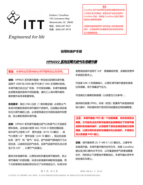
Enidine / Conoflow105 Commerce WayWestminster, SC 29693电话:(864) 647-9521传真:(864) 647-9574说明和维护手册HPNGV2 系列压缩天然气车用调节器警告:安装和启动系统前必须仔细阅读这些说明。
说明:HPNGV 系列调节器是一种自给式的降压调节器,适用于 3000 和3600 磅/平方英寸 CNG 车用燃料系统。
本调节器已经过出厂校准,不可现场调解。
本调节器根据应用需求提供各种不同的配置。
请向工人询问零件编号、维修套件或寻求配置帮助。
系统要求:高压 CNG 过滤(1 微米额定值)必须防止气体流中的颗粒物损坏调节器和下游部件。
过滤器必须安装在压力调节器的上游。
必须使用清洁无毛刺的连接件和管线,防止颗粒物损坏调节器。
连接:HPNGV 系列调节器通过进气口和排气口子连接至燃料系统。
这些端口使用 SAE J1926 O 型密封圈连接,其中进气口使用 3/8” 管件连接(9/16-18 螺纹),排气口使用 1/2” 管件连接(3/4-16 螺纹)。
排这些连接处有“进气”和“排气”标记。
进气和排气管线的尺寸必须合适,以容纳充足的气体流,且排气连接件的孔径必须至少为 3/8” ,以便于气流通过。
提供冷却液循环碗,以便发动机热量给调节器加热,防止调节器阀门内部结霜。
标准冷却液循环碗配有恒温器。
两个冷却液碗在连接处附近标记了冷却液进出口。
标准冷却液管线连接件适用于 3/8” 增强橡胶软管,该橡胶软管牢牢紧固在管夹上。
可选装 SAE-3 传感器端口,以便在调节器中直接安装高压传感器,用于测量进气压力。
可选装压力偏离控制装置(以歧管压力为参考)。
提供卸压装置 (PRD)。
标准(轻型)配置将气体直接排放到大器中,同时提供用于密闭空间或重型应用的捕集管。
注意:本调节器的 PRD 是一个控制装置,而非系统安全装置。
它可能无法在所有可能潜在的故障模式下对调节器或燃料系统提供保护。
压缩天然气(CNG)汽车基本知识

压缩天然气(CNG)汽车基本知识1、什么是压缩天然气(CNG)汽车?简单地说,压缩天然气(CNG)汽车是以天然气为燃料的一种气体燃料汽车。
天然气的甲烷含量一般在90%以上,是一种很好的汽车发动机燃料。
目前,天然气被世界公认为是最为现实和技术上比较成熟的车用汽油、柴油的代用燃料,压缩天然气(CNG)汽车已在世界和我国及我市得到了推广应用。
我国目前推广应用的是可分别燃用压缩天然气或汽油压缩天然气-汽油两用燃料汽车,简称CNG汽车,今后还将大力推广应用单燃料压缩天然气(CNG)汽车。
车用压缩天然气的压力一般在20MPa左右。
可将天然气,经过脱水、脱硫净化处理后,经多级加压制得。
其使用时的状态为气体。
2、压缩天然气(CNG)汽车的主要优缺点(1)压缩天然气(CNG)汽车是清洁燃料汽车.压缩天然气(CNG)汽车的排放污染大大低于以汽车为燃料的汽车,尾气中不含硫化物和铅,一氧化碳降低80%,碳氢化合物降低60%,氮氧化合物降低70%。
因此,许多国家已将发展压缩天然气(CNG)汽车作为一种减轻大气污染的重要手段。
(2)压缩天然气(CNG)汽车有显著的经济效益.可降低汽车营运成本。
目前天然气的价格比汽油和柴油低得多,燃料费用一般节省50%左右,使营运成本大幅降低。
由于油气差价的存在,改车费用可在一年之内收回.可节省维修费用。
发动机使用天然气做燃料,运行平稳、噪音低、不积炭,能延长发动机使用寿命,不需经常更换机油和火花塞,可节约50%以上的维修费用。
(3)比汽油汽车更安全首先与汽油相比,压缩天然气本身就是比较安全的燃料。
这表现在:燃点高。
天然气燃点在650。
C以上,比汽油燃点(427。
C)高出223。
C,所以与汽油相比不易点燃。
密度低。
与空气的相对密度为0.48,泄漏气体很快在空气中散发,很难形成遇火燃烧的浓度。
辛烷值高。
可达130,比目前最好的96号汽车辛烷值高得多,抗爆性能好。
爆炸极限窄。
仅5~15%,在自然环境下,形成这一条件十分困难。
压缩垃圾车使用说明书资料
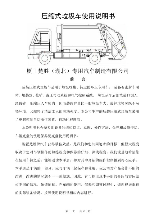
压缩式垃圾车使用说明书厦工楚胜(湖北)专用汽车制造有限公司前言后装压缩式垃圾车是用于垃圾收集、转运的环卫专用车。
•装备有密封车厢体、填装器、推铲、液压传动系统和电气控制系统。
•垃圾从车后部填装口倒入, 经破碎、压缩压入车厢内,因而装载容量比一般垃圾车大。
装卸垃圾时既不污染环境,又减轻了清洁工人的劳动强度。
本公司生产的后装压缩式垃圾车采用了电脑控制自动操作装置,自动化程度高。
本说明书只介绍专用设备的结构特点、原理、操作方法、保养和故障排除。
车辆底盘的使用保养见底盘使用说明书。
购置楚胜牌汽车获得最佳效益,是我们和您共同追求的目标,但很大程度取决于您对车辆操作的熟练程度和保养的仔细、深浅程度。
我们诚恳地希望您在使用车辆之前,能够通读本手册,并对其中介绍的操作程序做到得心应手。
本手册是车辆的一部分,应与车辆一起保存和使用。
我公司对产品会作不断的改进,改进的情况恕不一一通知您。
因此,有可能出现本手册的介绍与实际结构不同的情况,敬请谅解。
在车辆的使用、保养和调整过程中,请您根据车辆的实际装备情况,按照使用说明书相应内容进行。
一.概述采用载重质量3~12吨底盘改装生产的CSC5060ZYS~5250ZYS型系列压缩式垃圾车后装压缩型式,是厦工楚胜(湖北)专用汽车制造有限公司在吸收多种国内外同类产品优点的基础上,自主开发、设计的新一代后装压缩式垃圾车。
该车外形美观,性能优良,操纵控制先进,采用后装压缩和双向压缩技术完成对城镇生活垃圾的收集和转运,装载能力强,装载量大,其综合性能达到国内同类产品的先进水平。
底盘采用东风、解放等二类汽车底盘,品质优良,发动机功率强劲,排放达到国(欧)Ⅲ和国(欧)Ⅳ标准。
主要适用于城镇居民区、社区、大型厂矿和机关院校的桶装、袋装和散装生活垃圾的收运。
拥有多种翻桶(斗)机构,适用于不同用户的多种垃圾收集方式。
二.垃圾车外形图(以下几种为任选的代表车型)1.东风天锦后装压缩带摆臂(选装)2.东风福瑞卡后装压缩带挂桶(选装铁桶或塑料桶)3.东风天龙垃圾车三.主要技术参数和性能*.以上车型的参数只是列举部分,没有的车型参数以公告为准四.压缩式垃圾车的工作原理1. 垃圾压缩填装过程垃圾压缩填装过程见图一,步骤(1),为起始位置,当填装料斗装满垃圾后,刮板打开,作好插入松散垃圾的准备,步骤(2),滑板带动刮板一起向下移动,插入垃圾中进行破碎和首次压缩。
垃圾压缩站的操作规程
垃圾压缩中转站管理规范第一章挖板式垃圾压缩站操作规程一、开机前准备工作1、检查油箱中油液面的位置是否在油温表中部;2、检查电路是否连接坚固、完好;3、检查手动换向阀,手柄扳动是否灵便,住手位置是否可靠;4、检查各调压阀调节装置是否松动;5、挡轮块是否坚固,各举升油缸的挂钩是否有裂痕,固定是否牢靠。
二、开机步骤:1、先使各换向手柄处于中位;2、按启动开关,同时观察机电是否转动,转向是否正确(从上看为逆时针方向) 。
3 秒后再按运转按钮;3、进入动转状态后,观察各管接头处是否漏油,如漏油时,应即将住手,进行维修;4、举升油缸的各托钩转到不超过油缸防护罩位置。
三、卸下车箱1、用底盘液压压力把车车箱的推板收回车箱前部;2、卸下油泵进回油管的快速接头;3、卸下气管快速接头;4、卸下底盘的车尾灯光插头;5、拉开车箱底架的 4 个保险锁锁紧插销;6、先按启动开关,后按运转开关,开启压缩站的液压动力;7、把提升车箱的 4 个举升油缸托均摆正至车箱挂板,并观察托钩到位为止,方可向上提离底盘;8、车箱与底盘分离后,即可把底盘车慢慢驶离站;9、操作多路阀手柄,使车箱慢放下到位;10、把站里的高压油管快速接头接到车箱管快速接头上;11、把站里的油管快速接头接到车箱球阀的快速接头上,并把阀的手柄旋转90°直至限位处;12、接上 24 伏变压电插头,使电磁阀通电;13、使用站里的液压动力把车箱里的推板收置车箱尾部尽头。
四、装载垃圾装垃圾是使用站里的油压力,因此,多路阀的手柄可置在定位通道,只拨动车箱料斗的按钮,便可进行装载垃圾,垃圾装载完成,即把多路阀手柄推回中位,使油路循环,关闭电源。
五、车箱离站1、卸下 24 伏变压插头;2、卸下回油管快速插头;3、卸下压力管快速接头;4、观察提升车箱油缸的托钩位置是否正确,然后提高车箱至尽头位置;5、操作举升油缸阀手柄,使车辆平稳上升,密切注意车辆的厢体平稳;6、举升油缸彻底升出时,空底盘车退车至后轮接触到挡轮块,升使车辆外于两侧举升油缸的对中位置;7、操作举升油缸阀手柄,使车箱平稳下降,密切注意车箱与底盘上的挡块、拉销块是否对中,垃圾厢彻底位于底盘上后,继续使举升油缸收回,直到各举升油缸均回到收回下尽位置;8、拉动锁紧车箱底架插销,使车箱锁上;9、接回底盘油泵的吸油快速接头;10、接回油泵的压力管的快速接头;11、拨回球阀的手柄至极限位上; (底盘泵使用位置)12、推开提升车箱的 4 个托钩,当确认无障阻挡时,重车即可离站;13、插回七孔电插头温和管快速接头。
汽车空调压缩机的转动频率范围_解释说明
汽车空调压缩机的转动频率范围解释说明1. 引言1.1 概述汽车空调作为一种重要的车载设备,对提供舒适的驾乘环境起着至关重要的作用。
而汽车空调压缩机作为汽车空调系统的核心部件之一,其性能直接关系到空调系统的制冷效果和能耗。
在汽车空调压缩机中,转动频率是一个关键参数,它决定了压缩机工作时的转速范围。
因此,深入研究汽车空调压缩机的转动频率范围及其影响因素具有重要意义。
1.2 文章结构本文将从不同角度来解释和说明汽车空调压缩机的转动频率范围。
首先,我们将定义转动频率范围并讨论其在汽车空调系统中的意义(第2部分)。
接下来,我们将详细探讨影响汽车空调压缩机转动频率范围的因素(第3部分)。
然后,我们将介绍测量和评估汽车空调压缩机转动频率范围的方法与工具(第4部分)。
最后,在结论中总结研究结果并展望未来的研究方向(第5部分)。
1.3 目的本文的目的是通过全面分析和研究,深入了解汽车空调压缩机的转动频率范围以及其对系统性能的影响。
通过对转动频率范围的定义和意义进行探讨,并分析影响因素,可以为汽车制造商、研发人员和相关行业提供有关优化压缩机设计和改进汽车空调性能的指导和思路。
此外,我们还将介绍一些常用的方法和工具,帮助研究人员对汽车空调压缩机的转动频率范围进行准确测量和评估。
通过本文的研究成果,我们希望能够推动汽车空调技术的发展,并为提升驾乘体验和节能减排做出贡献。
2. 转动频率范围的定义与意义转动频率范围是指汽车空调压缩机在运行过程中能够稳定工作的转速范围。
它通常以转/分钟(rpm)来表示。
2.1 转动频率范围的定义汽车空调压缩机的转动频率范围可以理解为其有效工作范围,即在该范围内能够提供足够的制冷或加热效果。
这个范围一般由最低和最高的可接受转速确定。
2.2 转动频率范围的重要性转动频率范围直接影响着汽车空调系统的性能和效果。
如果压缩机无法在所设定的转速范围内正常运行,将会导致以下问题:- 不足的制冷或加热效果:当压缩机不能以所需的高速旋转时,系统无法充分地循环制冷剂或传热媒体,从而导致空调系统无法达到预期的制冷或加热效果。
汽车空调压缩机电控阀工作原理_解释说明

汽车空调压缩机电控阀工作原理解释说明1. 引言1.1 概述汽车空调系统中的压缩机电控阀是一个重要的组件,它在空调系统中起到关键的作用。
理解并研究汽车空调压缩机电控阀的工作原理对于提升汽车的空调性能和效率至关重要。
本文将详细介绍汽车空调压缩机电控阀的工作原理,并进一步解释其在整个空调系统中的作用和功能。
1.2 文章结构本文分为四个部分来讲解汽车空调压缩机电控阀的工作原理。
首先,我们将概述文章内容,并简要介绍每个部分涉及的主题。
然后,我们专注于第二部分,在此部分中将介绍压缩机的作用和原理以及电控阀的功能和作用。
接下来,在第三部分中,我们将详细解析电控阀的工作原理,并深入了解压缩机运行过程和电控阀的工作流程。
最后,在第四部分中进行总结,并对未来汽车空调压缩机电控阀的发展和建议进行展望。
1.3 目的本文旨在帮助读者全面了解汽车空调压缩机电控阀的工作原理,并对其在空调系统中的重要性和功能有更深入的认识。
通过解释说明压缩机运行过程、电控阀的工作流程以及系统调节和优化方法,我们希望读者能够获得对汽车空调压缩机电控阀的全面认知,并为未来的研究和发展提供一定的参考和建议。
通过本文内容的学习,读者将能够更好地理解并应用汽车空调压缩机电控阀相关知识,从而提升汽车空调系统的性能和效率。
2. 汽车空调压缩机电控阀工作原理:2.1 压缩机的作用和原理:汽车空调系统中的压缩机是一个关键部件,它负责将低压、低温的气体转化为高压、高温的气体。
通过增加气体的压力和温度,压缩机能够提供足够的冷媒流量来保证空调系统正常运行。
其原理基于连续循环的工作过程,通过不断吸入、压缩和排放冷媒来完成制冷循环。
2.2 电控阀的功能和作用:电控阀是汽车空调系统中另一个重要组成部分,它主要承担调节制冷剂流量和控制压缩机工作状态的任务。
电控阀能对冷媒流向进行精确控制,根据需要将相应数量的制冷剂送入蒸发器或绕过蒸发器直接返回到压缩机。
同时,电控阀还可以监测并保护系统,在高负荷或故障情况下对压缩机进行自动关闭以避免损坏。
压缩天然气(CNG)运输车知识要点精编精讲

压缩天然气(CNG)运输车知识要点精编精讲
(五)CNG运输车 CNG运输车,一般为高压气体运输车,其最重要、最特殊的组成部分是大 容积钢质无缝气瓶,如下图所示。 目前,国内CNG运输罐车主要生产厂家有石家庄安瑞科气体机械有限公司等。
12
压缩天然气(CNG)运输车知识要点精编精讲
二、大容积钢质无缝气瓶介绍 《大容积钢质无缝气瓶》(GB/T 33145-2016)中给出的定义为:水容积 大于150L-3000L,用于可重复重装压缩气体或液化气体的移动式钢质无缝气瓶。
6
压缩天然气(CNG)运输车知识要点精编精讲
天然气(主要成分为甲烷)是一种无色、无嗅的气体,通常因含有杂质而带 有特殊气味,天然气因组分不同密度稍有差异。典型的天然气标准状况下的密ቤተ መጻሕፍቲ ባይዱ 为0.717kg/m3,对空气的比重为0.5544,在通风场合泄漏的天然气很容易扩散, 天然气在空气中的爆炸极限为5~15%,当在相对密闭场合或在天然气大量泄漏 的情况下可以达到爆炸极限,遇明火会立即爆炸。
压缩天然气(CNG)运输车 知识要点精编精讲
2020.07
压缩天然气(CNG)运输车知识要点精编精讲
章节 一 压缩天然气相关知识介绍 二 大容积钢质无缝气瓶介绍 三 CNG运输车基本介绍 四 CNG运输车的使用和操作 五 CNG运输车安全管理要点 六 CNG运输车应急处理措施 七 CNG运输车的日常检查维护
10
压缩天然气(CNG)运输车知识要点精编精讲
(四)CNG汽车 CNG汽车是指以压缩天然气替代常规汽油或柴油作为汽车燃料的汽车。国 内外有天然气管网条件的地区均以发展CNG汽车为主。 CNG汽车是指主要由甲烷构成的天然气在25Mpa左右的压力下储存在车内 类似于油箱的气瓶内,用作汽车燃料。 主要工艺过程:在CNG加气站将0.3~0.8Mpa低压天然气,经过天然气压 缩机升压到25Mpa,由顺序控制盘控制,按高、中、低压顺序储存到储气钢瓶 组,再由CNG加气机向汽车钢瓶加注。而汽车钢瓶高压气再经过减压装置减压 后经燃气混合气向发动机供气。 CNG汽车优点: a、燃料价格便宜;b、汽车排气污染小;c、不积炭及车辆部件损耗小;d、 安全可靠;e、车辆改装简单;f、车辆运行平稳。
压缩式垃圾车的使用方法

压缩式垃圾车的使用方法
压缩式垃圾车是用于收集和压缩垃圾的专用车辆。
以下是压缩式垃圾车的基本使用方法:
1. 驾驶车辆到达垃圾收集点:将压缩式垃圾车驾驶到预定的垃圾收集点附近,确保车辆停放在平坦的地面上,以便安全操作。
2. 打开垃圾厢门:通过操纵控制面板或机械装置,打开垃圾厢门。
通常,压缩式垃圾车具有侧部或后部厢门,根据具体型号的不同,打开方式可能会有所不同。
3. 倒入垃圾:将垃圾从收集容器或垃圾桶倒入垃圾厢中。
确保遵守垃圾分类和处理的相关规定,并注意不要投放非法或危险废物。
4. 控制压缩操作:一旦垃圾厢倒满,可以通过操作控制面板或按钮来启动压缩操作。
该操作会使垃圾厢内的压缩装置开始工作,将垃圾压缩成较小的体积,以便增加储存容量。
5. 关闭压缩式垃圾车门:当垃圾厢中的垃圾被压缩并固定在一起后,
关闭垃圾厢门,确保密封。
6. 运送垃圾至处理场:一旦垃圾厢门关闭,驾驶压缩式垃圾车前往垃圾处理场。
在运输过程中,确保垃圾厢门牢固关闭,以防止垃圾散落和污染。
7. 垃圾处理和卸载:到达垃圾处理场后,按照相关规定进行垃圾的处理和卸载操作。
这可能包括将垃圾倾倒入处理设备或场地,并清理垃圾厢以准备下一次循环使用。
需要了解的是,具体压缩式垃圾车的使用方法可能会因不同的型号和制造商而有所变化。
因此,在操作之前,最好阅读和遵守相关的车辆操作手册,并接受相关培训和指导。
此外,确保遵守当地的垃圾分类、回收和处理规定,以促进环境保护和可持续发展。
汽车用电压缩机说明书

Please read this instruction manual carefully prior to operating this product.Pay particular attention to the CAUTION and WARNING statements in this manual. Failure to comply with these instructions could result in personal injury or property damage. Retain these instructions for future reference.DESCRIPTION:This portable oil-less air compressor is designed to operate on 12 volts DC and must be used with a power port that supports 10 amps or 120 watts (10A/120W). The unit comes in a rugged metal container, and includes a 3 pc. set of inflation tips. It can be used for inflating tires, sports balls, or topping off pressure for single person tube rafts, air mats, and other uses.75P AMP DRAW WARNING:Most automotive cigarette lighter/power ports handle up to 10A/120W, though some vehicles’ power ports may have lower amp ratings. Before purchasing and using this unit, inspect the amp draw limitations of your vehicle’s power port. The 75P Portable Air Compressor requires a power port rated for 10 amps or 120 watts. Never replace fuses of higher amp rating beyond the original rating of the circuit. Consult your vehicle’s manual for further details.IMPORTANT SAFETY INSTRUCTIONS:CAUTION: The compressor has been designed to provide long-term, trouble-free operation.To reduce risk of electrical shock or electrocution and to prevent damage to your compressor, follow these simple guidelines:1. Do not disassemble. Do not attempt to repair or modify this unit.2. Never allow children to operate this compressor. Close supervision is necessary when thiscompressor is being used near children.3. This compressor will become very hot during and immediately after use.Do not touch any part of this compressor with bare hands, other than the ON/OFF switch and carry handle, during or immediately after use.4. Provide sufficient cooling time before replacing the lid.5. Never operate the compressor near fire, flammable gas or liquid.6. There are no user-serviceable parts in this unit, no lubrication is required.7. Do not pump anything other than atmospheric air.8. Never use this product while sleepy or drowsy.9. Be sure the unit’s power switch is in the OFF position when not in use.10. U se only in well ventilated areas.11. Never carry the air compressor by the hose or power cord.12. Never point air nozzle towards another person or any part of the body.13. Inflate items only to their manufacturer’s recommendations pressures.14. D o not leave air compressor running unattended. It could burst tires or other items.FEATURES:1. 10 amp Accessory Power Port Plug2. 3-Pc. Inflation Tips Kit3. Press-On Chuck4. Rugged Metal Container5. Piston Type Compressor6. Oil-Less Design7. Gearless Direct-Drive Motor8. Permanently Lubricated Bearings9. Compact Size for Easy Carrying and Storage10. H igh Strength Stainless Steel Valves11. A nodized Aluminum Alloy Cylinder12. 60 PSI GaugeOPERATING INSTRUCTIONS:CAUTION: To avoid over inflation, never exceed recommended pressure. Doing so may cause articles to burst and can cause serious bodily injury. Always make sure the Portable Compressor’s power cord is uncoiled and fully extended when using your air compressor to avoid overheating the power cord.INFLATING CARS & MOTORCYCLE TIRES:IMPORTANT: Engine must be running while using this compressor.1. The compressor is designed to operate on 12 volts DC. To obtain power,plug the power cord into a 12-volt cigarette lighter socket or other 12-volt power source.2. Start vehicle’s engine to provide charging voltage.3. Attach the end of the air hose to the tire valve stem.4. Turn the compressor power switch to ON and begin to inflate tire.5. When the gauge indicates the desired pressure, switch the unit OFF andremove the air hose from the tire valve stem.FOR ALL OTHER INFLATABLE OBJECTS, INCLUDINGBICYCLE TIRES, TOYS, AND SPORTS BALLS:IMPORTANT: Engine must be running while using this compressor.1. A selection of inflation tips is provided to fit some inflatable objects.Simply clamp the appropriate nozzle into the press on tire chuck of the air hose.2. Attach the appropriate nozzle to article to be inflated, start vehicle’s engine to provide chargingvoltage, and turn the power switch to the ON position.3. When article is inflated to desired firmness, turn the compressor off. Do not over inflate. Please Note: During inflation, due to air velocity, pressure gauge cannot provide accurate pressure readings, to check and verify the actual tire pressure the compressor must be in OFF position. MAINTENANCE INSTRUCTIONS:Turn OFF and unplug Air Compressor. Your air compressor is equipped with a permanently lubricated, maintenance-free motor. Never try to lubricate the compressor. Use only mild soap and a cloth dampened with hot water to clean plastic parts. Avoid any type of detergents or solvents, which might contain chemicals that could damage plastic portions or painted surfaces of the compressor. All other services should be performed by a qualified person.。
加氢站压缩氢气卸车操作规范T∕CECA-G 0082-2020
加氢站压缩氢气卸车操作规范1范围本文件规定了加氢站压缩氢气卸车操作的通用要求和长管拖车卸车操作规范。
本文件适用于氢气压缩机额定工作压力不大于45MPa的加氢站及加氢合建站。
2规范性引用文件下列文件中的内容通过文中的规范性引用而构成本文件必不可少的条款。
其中,注日期的引用文件,仅该日期对应的版本适用于本文件;凡是不注日期的引用文件,其最新版本(包括所有的修改单)适用于本文件。
GB4962氢气使用安全技术规程GB/T24499氢气、氢能与氢能系统术语GB/T34584加氢站安全技术规范GB/T37244质子交换膜燃料电池汽车用燃料氢气GB50516加氢站技术规范TSG07特种设备生产和充装单位许可规则TSG Z6001特种设备作业人员考核规则3术语和定义GB/T24499、GB/T34584和GB50516中界定的以及下列术语和定义适用于本标准。
3.1氢气储存系统hydrogen storage system由用于储存压缩氢气的气瓶、气瓶组、储氢罐或气瓶集束装置以及相关联的管路、阀门、接头、压力表和安全附件等组成的系统。
4通用要求4.1作业人员的要求4.1.1担任技术负责人职务的,应符合TSG07的相关规定,应当具有工程师任职资格。
4.1.2车用氢气气瓶作业人员(安全管理负责人、充装员、充装检查员)应当符合TSG Z6001的相关规定。
4.2氢气储存系统的要求氢气储存系统及设备应符合GB/T34584有关规定。
4.3压缩氢气卸车作业区域的要求4.3.1卸车作业区域应符合GB/T34584有关规定。
4.3.2卸车作业区域防静电接地、防甩绳以及地面车辆防滑等安全设施应完好。
4.4吹扫置换的要求氮气吹扫置换应符合GB4962的相关规定。
5长管拖车卸车操作规范5.1泄漏检查5.1.1作业人员应指挥长管拖车驶入在作业区以外的泄漏检查场地内,并停留在指定的位置进行泄漏检测。
进入泄漏检查场地的汽车车速不得超过5km/h。
- 1、下载文档前请自行甄别文档内容的完整性,平台不提供额外的编辑、内容补充、找答案等附加服务。
- 2、"仅部分预览"的文档,不可在线预览部分如存在完整性等问题,可反馈申请退款(可完整预览的文档不适用该条件!)。
- 3、如文档侵犯您的权益,请联系客服反馈,我们会尽快为您处理(人工客服工作时间:9:00-18:30)。
压缩车使用说明
一操作步骤
在装载垃圾前,空载运转达到 6 个标准时,挂上取力器(驾驶室内方向盘左下方),检查各部件有无泄漏或异常后,再按照操作旋钮牌指示位置进行操作;
后斗操作板(斗体侧面)驾驶室操作板(驾驶室内)其具体操作步骤如下:
一装垃圾 1.旋转翻桶(板)操作旋钮至左下翻位,使翻桶(板)机构放下,松开旋钮回中位,然后旋转刮板操作旋钮至右收起位,刮板收起,松开旋钮回中位,准备开始挂桶。
2.挂上垃圾桶,旋转翻桶操作旋钮至右上翻位置,垃圾桶向上翻转,垃圾自动卸入圆弧形斗体内,松开旋钮回中位; 3.旋转翻桶操作旋钮至左下翻位置,垃圾桶回置,松开旋钮回中位;然后旋转滑板操作旋钮至左下滑位置,滑板下滑(注意:刮板在向上收的位置),松开旋钮回中位,准备收刮垃圾; 4.旋转刮板操作旋钮至左刮起位置,刮板沿圆弧斗体刮起垃圾,松开旋钮回中位;5.旋转滑板操作旋钮至右上滑位置(注意:刮板下油缸座必须超过行程开关标记位置),滑板带动刮板同时上滑,松开旋钮回中位,垃圾被刮板带起,准备推进垃圾; 6.旋转
负压操作旋钮至右推出位置,垃圾被负压板推入车箱内,松开旋钮回中位;7.旋转负压操作旋钮至左收回位置,负压板收回,松开旋钮回中位,完成 1 次垃圾的装载;若再次装载垃圾,请再继续从步骤1(旋转刮板操作旋钮至收位,准备开始挂桶)开始循环操作;若不需要再次装载,旋转翻桶操作旋钮至右上翻位置,翻桶机构翻起,然后松开取力器,整车方可移动。
二卸垃圾
8. 在卸垃圾前,整车运转达到 6 个标准气压时,挂上
取力器,在前级二联多路阀处旋转举斗操作旋钮至右
举起位置,斗体被举起,松开旋钮回中位,准备卸垃圾;
9.旋转推板操作旋钮至右推出位置,车箱内推板将垃圾
推出车箱,松开旋钮完成卸垃圾工作;10.旋转推板操
作旋钮至左收回位置,推板被收回,松开旋钮;再旋转
举斗操作旋钮至左下落位置,斗体放下并与车箱锁紧,
松开旋钮,同时松开取力器(若翻桶机构为放下位置,
请将其翻上),此时整车可移动。
手动手柄操作(此操作应在电控旋钮失灵时应急使用)
二维护保养
1、汽车底盘和发动机部分的使用与保养按底盘车使用说明书的规定进行。
2、新车在走合阶段,行驶里程在1500-2500km 和举箱(推板)卸料900 次以内,装载量以额定载质量的70%进行,卸料时发动机不得锰轰油门。
3、在油缸工作300 次以后,应更换全部工作油。
拧开液压油箱放油螺塞,再从上部加油孔注入新机油,然后启动发动机,试运行各油缸动作两次,确认工作可靠即可。
4、高压油管每两年定期更换。
在使用过程中发现有龟裂、损坏、肩部膨胀等现象时,应及时更换。
5、经常检查液压系统漏油情况,并及时维修和更换油封。
6、润滑采用汽车通用锂基润滑脂(GB5671-85),可用油枪从油嘴中打入,直至间隙中挤出为止。
7、每天作业结束后清洗整车及车箱、填压器内表面。
经常检查液压油存量,定期给各运动部位加注润滑油、各导轨表面涂抹润滑油。
8、定期检查并调教齿轮油泵工作压力;检查滤油器滤芯,清除表面杂质或更换滤芯;定期更换液压油。
三注意事项
1、该系列垃圾车严禁投入建筑垃圾物,以免损坏机件。
2、液压系统操作时如发现运动异常,应立即停止工作,分析原因,排除故障。
切勿强制施压作业。
3、无论是啮和还是脱开取力器,都必须踏下离合器踏板;取力器和多路换向阀处于工作状态时,垃圾不得进入行驶状态。
4、液压系统的调压装置为多路换向阀上的调压螺栓,该螺栓经校压调定并锁紧后,使用中不得随意调动。
用户不允许随便调整油压。
5、填压器顶部的单向节流阀是控制填压器下降速度的装置,调定并锁紧后不得随意调动。
6、车辆集收斗的关闭应使集收斗下降到底,锁舌和锁块咬合,关闭才告结束。
7、洗车时不得将水冲入液压油箱内。
经常检查液压油面高度,液压油不足时要及时加注,全部油路接头不得漏油。
8、检修时应防止碰撞,避免零件损伤、变形及划痕等。
装配零件时必须注意清洗干净。
四、液压系统故障判断及处理
液压机构工作不正常时。
应首先检查取力器是否正确啮
合,油箱内液压油是否充足,吸油管球阀是否完全开
启。
1、液压机构无动作,按下列步骤依此检查。
a、液压油箱内油量是否充足。
不足时应加注液压油;
b、观察油箱到油泵的进油管是否因老化而产生轰油吸瘪
现象。
如有此现象则应更换进油管。
c、检查是否齿
轮油泵失效。
装上压力表,拧动调压螺栓,观察表是否
达到规定值;d、如调压螺栓全部拧入后仍达不到规定
油压,则是齿轮油泵失效,须更换齿轮油泵;e、如齿
轮油泵工作正常,则是多路换向阀阀芯堵塞。
应拆下阀
芯,清除杂质,重新装入后使用。
2、液压机构有动作但无力检查齿轮油泵是否失效,系统压力是否达到规定值。
3、液压机构动作变慢检查齿轮油泵是否失效、吸油滤油器、回油滤油器芯是否堵塞。