Buck变换器的电感计算
buck计算公式
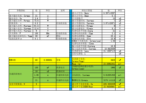
单位 A V W
说明
经验假设值 W V V KHz mV
经验假设值 指标 经验假设值
理论计算值 最小占空比:Dmin 最大占空比:Dmax 开关周期:T 最大导通时间:Ton-max 最小导通时间:Ton-min 最大电感电压:Vl-max 最小电感电压:Vl-min 电感电流平均值:Ilavg 电感电流纹波值:Ilpp 电感电流峰值:Ilpk 电感电流谷值:Ilvy CCM最小负载电流:Io-min(ccm) 电感电流有效值:Ilrms 输入电流平均值:Iin-avg 输入电流有效值:Iin-rms 电感最低值:Lmin 实际电感值:L 纹波最小电容: Co-min(Vrpp) Resr(to) 负载阶跃响应最小电容: Co-min(load) 目标阻抗:Zco-max BUCK电容:Co-min 最小单个电容容量:Co 最大单个电容ESR:Resr 最小输入电容:Cin-min 最小输入电容:Cin-min
可不计算 可不计算 可不计算
参数指标 最大输出电流:Io-max 输出电压:Vo 最大输出功率:Po-max 转换效率:η 最大输入功率:Pin-max 最大输入电压:Vin-max 最小输入电压:Vin-min 开关频率:F 最大输出纹波电压:Vrpp 电流纹波率:r
值 21 3.6 75.6 0.8 94.5 12.6 9 100 50 0.1
值 0.357142857 0.4 10 4 3.571428571 9 5.4 21 2.1 23.1 18.9 1.05 10.5 10.0623059 21.42857143
单位
uS uS uS V V A A A A A
uH uH uF mΩ uF mΩ uF uF mΩ uF uF
buck电感计算公式

buck电感计算公式
Buck电感计算公式
1. 电感的基本公式:
电感L = 线包的外径×线包的长度×线包的电导率÷2π
2. 将线包长度换成全模值:
电感L = 线包的外径×2π×M×电导率÷4π
3. 根据Buck电路设计特性计算电感:
电感L = (输出电压÷ switchingFrequency)× (全模值、pm)
4. Buck电路输入电压和输出电压:
电感L = (Vin - Vout)÷ (switchingFrequency × inductorCurrent)
5. 其他因素:
(1) 如果input voltage很小,可以使用可调电阻来调整输出电压;
(2) 如果output voltage需要很高,可以把一系列的Buck电路连接起
来;
(3) 如果switchingFrequency过低,可以使用更大的电感提高效率;
(4) 如果switchingFrequency要求太高,可能需要把电感变大一些,以抵消振荡风扇的影响。
buck电路电感计算公式推导
buck电路电感计算公式推导摘要:1.Buck 电路概述2.Buck 电路电感计算公式推导过程3.Buck 电路电感计算公式的实际应用正文:一、Buck 电路概述Buck 电路,又称降压电路,是一种DC-DC 变换器,其作用是将高电压转换为较低电压的电源。
在Buck 电路中,电感元件起到了关键性的作用。
为了更好地理解和计算Buck 电路中电感的值,我们需要了解其电感计算公式的推导过程。
二、Buck 电路电感计算公式推导过程1.基本原理Buck 电路的工作原理是通过在输入端开关的控制下,使电感上的电流呈锯齿波形,从而实现输出电压的调节。
在电路稳定运行时,电感器上的电流和电压关系可以用以下公式表示:i_L = (Vout - Vin) / L其中,i_L 为电感器上的电流,Vout 为输出电压,Vin 为输入电压,L 为电感值。
2.推导过程根据基本的电磁感应原理,电感上的感应电动势(EMF)与电感值和电流变化率成正比。
对于Buck 电路,我们可以将电感器上的电流表示为:i_L = (1/L) * (di/dt) * L其中,di/dt 表示电流的变化率。
在稳态运行时,电流变化率为0,因此有:i_L = 0将i_L 代入上式,得到:0 = (1/L) * (di/dt) * L因为电感器上的电流为0,所以可以得到:i_L = (Vout - Vin) / L通过以上推导,我们得到了Buck 电路中电感计算公式。
三、Buck 电路电感计算公式的实际应用在实际应用中,根据所需的输出电压、输入电压以及开关的占空比,可以通过以下公式计算电感值L:L = (Vout - Vin) / (i_Lmax - i_Lmin)其中,i_Lmax 为电感器上的最大电流,i_Lmin 为电感器上的最小电流。
根据实际电路参数,可以求解得到合适的电感值,从而实现Buck 电路的稳定运行。
综上所述,我们通过对Buck 电路电感计算公式的推导,了解了其计算过程,并明确了在实际应用中如何根据电路参数计算合适的电感值。
BUCK电路电感选择和计算
如今,隨著傳輸資料流程的需要,電子產品的耗電量與日俱增,開關電源的頻率也越來越高,並且對整個電壓模組的速度和尺寸要求也越來越嚴格。
電感已經成為所有電源拓撲結構的基本元件,在工業,自動化和DC-DC轉換器上廣泛使用。
特別是滿足從0到60A電流大小的範圍內對電感提出了更高的要求。
電感在電子三元件電感、電容與電阻之中,乃居於產品設計轉換的關鍵地位,電感類元件,必須經過一一的設計與測試才能決定。
考慮到目前電感器繁多的規格和種類,在下一代電子產品設計中為電源轉換電路選擇一個好的電感並不簡單,設計者必須在瞭解電感理論的基礎上,再根據結構,額定電流,磁芯材料,磁芯損耗,溫度和飽和電流綜合評價,選擇最佳電感參數。
另外值得慶倖的是,許多電感供應商都提供尺寸和性能優秀的產品,甚至還可以修改產品參數以滿足用戶需求的服務。
電感簡介電感、電阻和電容合稱為三大被動元件,其電器特性雖然各有不同,但卻都是3C產品中不可或缺的關鍵元件。
電感的主要功能為穩定電流與去除雜訊,另可搭配電阻與電容展現多種功能,故在機器、設備、消費性電子、電力配輸與抑制電磁輻射方面被廣泛運用。
對電感的需求亦因而與日俱增。
電感的上游主要是以鎳鋅與錳鋅鐵氧體磁芯兩大系列為主,因材料特性之不同,分別應用於資訊和通訊產品上。
鐵氧體磁芯(Ferrite Core)是以高溫燒成的金屬氧化物,主要作為高頻線圈及變壓器等產品之磁芯。
電感的發展趨勢主要是因應系統產品的發展而變化。
在電腦及其周邊資訊產品方面,由於對空間需求的迫切性不高,電感的發展以朝向產品體積小型化與發展排列式晶片電感為主。
在通訊產品方面,由於該類產品對空間需求迫切度高,因此電感器除了朝向小型化發展外,亦需進一步開發整合型元件以因應產品的需求;此外,為因應產品高頻化的發展,電感亦需提高其使用頻率,而朝向陶瓷等高頻材料及元件開發。
整體而言,未來電感器將朝向小型化、高頻化及整合化發展。
電感參數當導線內通過交流電流時,在導線的內部及其周圍產生交變磁通,導線的磁通量與生產此磁通的電流之比。
Buck电感计算
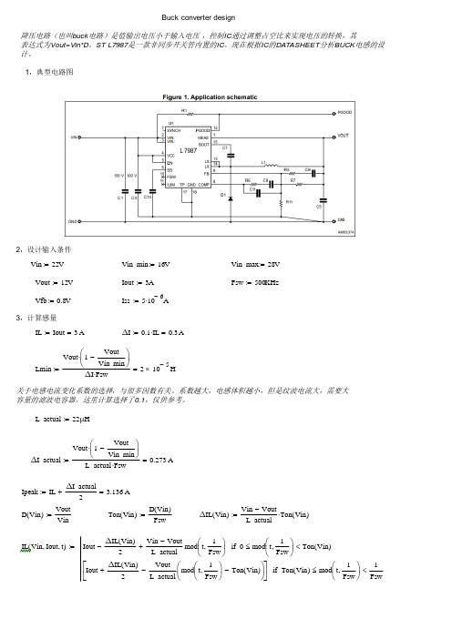
Buck converter design降压电路(也叫buck电路)是值输出电压小于输入电压,控制IC通过调整占空比来实现电压的转换,其表达式为Vout=Vin*D。
ST L7987是一款非同步开关管内置的IC。
现在根据IC的DATASHEET分析BUCK电感的设计。
1,典型电路图2,设计输入条件Vin22V:=Vin_min16V:=Vin_max28V:=Vout12V:=Iout3A:=Fsw500KHz:=Vfb0.8V:=Iss5106-A⋅:=3,计算感量IL Iout3A=:=ΔI0.1IL⋅0.3A=:=关于电感电流变化系数的选择,与很多因数有关。
系数越大,电感体积越小,但是纹波电流大,需要大容量的滤波电容器。
这里计算选择了0.1,仅供参考。
L_actual22μH:=4,开关管电流波形,续流二极管电流波形从两个器件的波形图可以看出BUCK电路的工作过程,开关管导通的时候,电感电流上升,电感储存能量,续流二极管处于关闭状态,无电流。
开关管关闭后,电感电流下降,电感释放能量,续流二极管处于导通状态,且电流减小。
5,电感设计电感在一个周期中有储存能量和释放能量的过程,磁芯磁路中需要高磁阻部分来担任这个作用。
常用的几种电感结构有:工字/棒形磁芯(开磁路);气隙铁氧体;金属磁粉芯;气隙非晶磁芯a)选择铁氧体磁芯AP 法选择磁芯Aw=N*Irms/J/Ku Ae=L*Ipeak/N/Bm Ap=L*Ipeak*Irms/Ku/J/BmEQ18Ae 30102-⋅cm2:=Le 2.17cm :=Ve 668103-⋅cm 3:=ur 1800:=选择3*0.25mm 扁线可以满足要求计算磁芯气隙计算损耗ID 7.2mm :=ρ 2.33108-⨯Ωm⋅:=L_cu 3.14ID W +()⋅N_actual ⋅ 1.05⋅0.336m=:=P_cu Irms 2R_cu ⋅0.094W=:=Ptotal P_fe P_cu +0.094W =:=计算温升L_core 18mm :=W_core 9.7mm :=H_core 6.3mm:=As 2L_core W_core ⋅L_core H_core ⋅+W_core H_core ⋅+()⋅ 6.982104-⨯m 2=:=ΔT 2956.9820.7-⋅0.0940.85⋅10.144=:=b)选择金属磁粉芯Bm_powder 0.5T:=D_choose 1.0mm:=初选磁芯KS065125A -根据计算软件得到设计值如下:L031.75μH:=L_3A 24.76μH :=P_core 0.1W:=P_wire 0.16W :=金属磁粉芯的设计有软件可以帮助,相关计算公式供应商也可以提供,包括损耗计算公式,电感下降比例计算,温升等各种。
正激电感的计算以及验算
正激式转换拓扑之 BUCK电感计算相对于线性调整器,BUCK转换器提供了高的多的效率,功率密度大幅提高,现在一些流行的专业BUCK控制IC制作的电源其功率密度甚至可以达到50W/inch^3. 广泛用于板级电源系统。
设计一个性能满足需要的BUCK转换器,首先应保证一个具有合理的参数的储能电感。
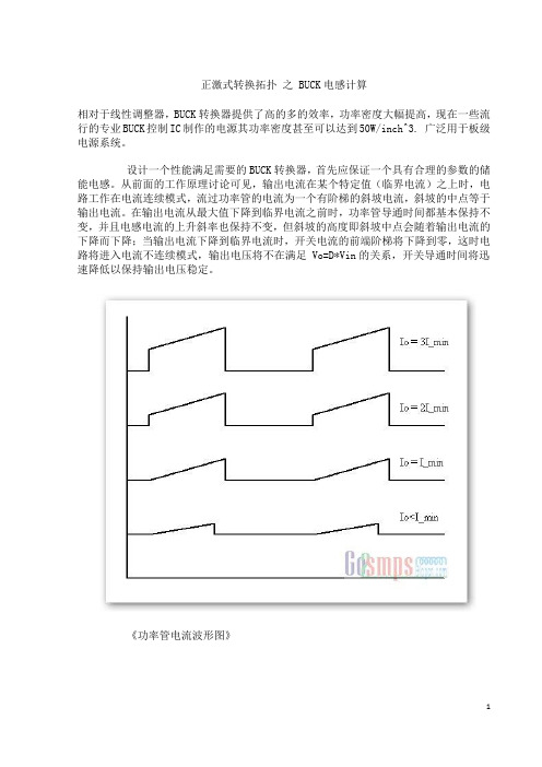
从前面的工作原理讨论可见,输出电流在某个特定值(临界电流)之上时,电路工作在电流连续模式,流过功率管的电流为一个有阶梯的斜坡电流,斜坡的中点等于输出电流。
在输出电流从最大值下降到临界电流之前时,功率管导通时间都基本保持不变,并且电感电流的上升斜率也保持不变,但斜坡的高度即斜坡中点会随着输出电流的下降而下降;当输出电流下降到临界电流时,开关电流的前端阶梯将下降到零,这时电路将进入电流不连续模式,输出电压将不在满足 Vo=D*Vin的关系,开关导通时间将迅速降低以保持输出电压稳定。
《功率管电流波形图》临界电流的大小主要取决于储能电感的感量。
通常需要设定一个最小输出电流作为临界电流。
如果设临界电流与输出电流的比值为 K, 则输出储能电感感量 Lp 可由如下公式给出:Lp=(Vin-Vo)*Vo*T/(2*K*Vin*Io)在一般的应用中常选取输出电流的10%作为最小输出电流,这主要是在折衷负载调整率和输出响应的结果,过小的临界电流将导致电感感量较大,输出负载调整率较好,但瞬态响应变差,输出过冲变大;较大的临界电流可有效改善输出过冲和瞬态响应,但需要更大的最低输出电流才能得到较好的输出负载调整率。
另外,一个容易忽略的问题是电感饱和,储能电感工作在一个高直流成分的条件下极易出现饱和现象,电感值下降,甚至失去电感量,设计时应保证在输出少许过载的情况下电感也不会进入饱和状态。
对于待使用的电感可以使用如下参数简单计算一下可能的最大磁通密度,检验是否会出现饱和现象:Bs=(Lp*I_max)/(Ae*Np)其中,Lp是最大开通电流下的电感量(uH), I_max是最大开通电流(A), Ae 是磁心有效截面积(mm^2), Np是电感的绕线匝数(Ts). 磁心所能承受的最大不饱和磁通密度可查阅厂商相关资料。
Buck开关电源变换器输出滤波电感计算

Buck变换器输出滤波电感计算案例:输入电压:15V;(为简单,假定输入电压不变化)输出电压:5V,电流:2A;工作频率:250kHz电感量:35μH,电流0到2A允许磁芯磁通变化部超过20%,即电感量变化不超过20%;绝对损耗:300mW自然冷却,温升ΔT:40℃根据以上要求可以得到D=5/15=0.33; 纹波电流峰峰值d I=U d t/L=(15-5)(33%×4μs)/35μH=0.377A(约为直流分量的20%);电感绝对损耗为300mW,磁芯损耗和线圈损耗各占50%,所以最大损耗电阻为R=P/I2=150mW/22 =37.5mΩ。
电感变化量小于20%,这就意味着,临界连续时需要的电感是44μH(44μ×80%=35μH)。
1、磁芯选择方法:因为工作频率高,采用MPP材料的磁粉芯,因而必须有Magnetics公司的产品手册。
步骤如下:计算要求的电感存储的能量→查阅磁芯选择指南→获得磁芯型号和μ→查找磁芯尺寸→查得AL→根据要求的电感量试算所需匝数→计算磁场强度→查阅磁导率下降百分比→达到要求的电感增加还是减少匝数→改选磁芯→重复以上步骤,直到达到要求的电感量→计算导线尺寸→计算铜损耗→计算脉动磁通密度分量→计算磁芯损耗→计算总损耗→计算磁芯温升,保证在合理范围内2、初算:这里采用MPP磁粉芯设计我们的电感,首先查阅Magnetics公司的手册。
从手册中找到选择指南图5-7,这里是设计是开始点。
如果没有磁芯选择指南,也可以根据以前设计凭经验确定。
虽然第一次试选不是十分重要,但它可以减少你的工作量。
从电感所要存储的能量(是实际值的两倍)开始。
在2A时电感量35μH(0.035mH),两倍的能量为(2A)2×0.035=0.14mJ。
在图5.6上由0.14mJ纵向画一直线,与300μ磁芯(磁芯初始磁导率为300)相交,交点向右找到纵坐标上的代号55035和55045磁芯之间,暂选择55045磁芯。
Buck电路电感感量计算
Buck变换器别名叫降压变换器,串联开关稳压电源,作用是把输入高电压转换成人们需要的低压。
不要市电是AC220V,整流滤波后是310V的直流,大多电子产品是低压电路,一般是5V、12V、24V、36V、48V等,这些低压的电子设备不能直接应用输入AC整流后的直流电压,必须用一个转换器转换成所能应用的低电压。
当然能把高压转化成低压的转换器有很多种,Buck只是其中的一种,他的优点是效率高,体积小,不电感放电时间为Tm,其中:dt为导通时间Ton,最大占空比····················公式1最小占空比····················公式2在临界模式里开关管开通时间·············公式3开关管关断时间··············公式4又因为··············公式5根据占空比的公式输入电压变高的时候D变小,所以Ton变小,一个周期里面电感的平均值电流Io是不变的,假设电感峰值电流不变,那么电感流过电流与时间形成的三角形面积=Io×T,周期T是固定,Ton变小,如果峰值电流不变也就是△I也不会变,输出电压固定Tm也不变,T不变,这样就会导致Io变小,与前面要求的Io不变相违背,要想Io 不变,只有峰值电变大。
BUCK电路电感选择和计算

BUCK电路电感选择和计算如今,隨著傳輸資料流程的需要,電⼦產品的耗電量與⽇俱增,開關電源的頻率也越來越⾼,並且對整個電壓模組的速度和尺⼨要求也越來越嚴格。
電感已經成為所有電源拓撲結構的基本元件,在⼯業,⾃動化和DC-DC轉換器上廣泛使⽤。
特別是滿⾜從0到60A電流⼤⼩的範圍內對電感提出了更⾼的要求。
電感在電⼦三元件電感、電容與電阻之中,乃居於產品設計轉換的關鍵地位,電感類元件,必須經過⼀⼀的設計與測試才能決定。
考慮到⽬前電感器繁多的規格和種類,在下⼀代電⼦產品設計中為電源轉換電路選擇⼀個好的電感並不簡單,設計者必須在瞭解電感理論的基礎上,再根據結構,額定電流,磁芯材料,磁芯損耗,溫度和飽和電流綜合評價,選擇最佳電感參數。
另外值得慶倖的是,許多電感供應商都提供尺⼨和性能優秀的產品,甚⾄還可以修改產品參數以滿⾜⽤⼾需求的服務。
電感簡介電感、電阻和電容合稱為三⼤被動元件,其電器特性雖然各有不同,但卻都是3C產品中不可或缺的關鍵元件。
電感的主要功能為穩定電流與去除雜訊,另可搭配電阻與電容展現多種功能,故在機器、設備、消費性電⼦、電⼒配輸與抑制電磁輻射⽅⾯被廣泛運⽤。
對電感的需求亦因⽽與⽇俱增。
電感的上游主要是以鎳鋅與錳鋅鐵氧體磁芯兩⼤系列為主,因材料特性之不同,分別應⽤於資訊和通訊產品上。
鐵氧體磁芯(Ferrite Core)是以⾼溫燒成的⾦屬氧化物,主要作為⾼頻線圈及變壓器等產品之磁芯。
電感的發展趨勢主要是因應系統產品的發展⽽變化。
在電腦及其周邊資訊產品⽅⾯,由於對空間需求的迫切性不⾼,電感的發展以朝向產品體積⼩型化與發展排列式晶⽚電感為主。
在通訊產品⽅⾯,由於該類產品對空間需求迫切度⾼,因此電感器除了朝向⼩型化發展外,亦需進⼀步開發整合型元件以因應產品的需求;此外,為因應產品⾼頻化的發展,電感亦需提⾼其使⽤頻率,⽽朝向陶瓷等⾼頻材料及元件開發。
整體⽽⾔,未來電感器將朝向⼩型化、⾼頻化及整合化發展。
buck电路电感峰值电流计算

电感是电路中常用的元件之一,在电路中起着存储能量和限制电流变化的作用。
在设计电路时,我们经常需要计算电感元件的峰值电流,以确保电感元件能够正常工作。
本文将介绍如何计算buck电路中电感元件的峰值电流,以及计算过程中需要考虑的因素。
一、buck电路简介1. 什么是buck电路buck电路是一种降压型的开关电源电路,通过开关元件(如MOS管)来实现输入电压的降压输出。
在buck电路中,电感元件起着储能和滤波的作用,是电路中不可或缺的元件之一。
2. buck电路的工作原理buck电路通过开关管的通断来实现对输入电压的调节,当开关管导通时,电感元件储存能量;当开关管断开时,电感元件释放能量,从而实现对输出电压的调节。
二、电感峰值电流的定义在buck电路中,电感元件的峰值电流是指电感元件在工作周期内的最大电流数值。
计算电感峰值电流的目的是为了选择合适的电感元件,以确保电路正常工作。
三、电感峰值电流的计算1. 峰值电流公式电感峰值电流Ipeak可以通过以下公式计算得出:Ipeak = Vin * (1 - D) / (L * f)其中,Vin为输入电压,D为占空比,L为电感值,f为开关频率。
2. 计算步骤(1)确定输入电压Vin和开关频率f的数值;(2)根据电路需求,确定占空比D的数值;(3)根据设计要求,选择合适的电感值L;(4)代入公式,计算得出电感峰值电流Ipeak。
四、影响电感峰值电流的因素在计算电感峰值电流时,需要考虑的因素有很多,下面我们简单介绍一下主要因素:1. 输入电压Vin:输入电压的大小直接影响了电感峰值电流的大小,因此在计算过程中需要准确确定输入电压的数值。
2. 开关频率f:开关频率的增大会减小电感峰值电流,因此在设计电路时需要考虑开关频率的选择。
3. 占空比D:占空比的大小直接影响了电感峰值电流的大小,因此需要根据设计要求确定合适的占空比数值。
4. 电感值L:电感值的选择也会直接影响电感峰值电流的大小,因此需要根据设计要求选择合适的电感值。
boost及BUCK电感计算
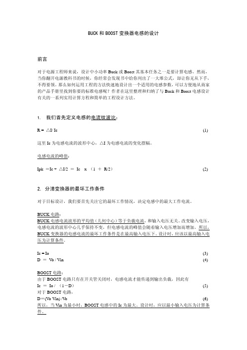
BUCK和BOOST变换器电感的设计前言对于电源工程师来说,设计中小功率Buck或Boost其基本任务之一是要计算电感。
然而,当你翻开电源教科书的时候,你经常会发现书中给你列出了一大堆公式,却让你无从下手,不得要领。
那么如何运用工程的方法快速地设计出一个适用的电感参数,可以方便地从商家的产品手册里找到你要的标准电感呢?作者在这里整理和归纳了与Buck和Boost电感设计有关的一系列实用计算方程和简单的工程设计方法。
1. 我们首先定义电感的电流纹波比:R = △I/ Ic (1) 这里Ic为电感电流的波形中心,△I为电感电流的变化摆幅。
电感电流的峰值:Ipk =Ic + △I/2 = Ic x (1 + R/2)(2) 2.分清变换器的最坏工作条件对于目标设计,我们要首先关注它的最坏工作情况,决定电感中的最大工作电流。
BUCK电路:BUCK电感电流波形的平均值(几何中心)等于负载电流,和输入电压无关。
改变输入电压,电感电流的波形中心几乎保持不变,但电感电流的峰值会随着输入电压增加而增加。
所以,BUCK变换器的电感电流的最坏工作条件是在最高输入电压下。
设计时,应该以最高输入电压为计算条件。
Ic = Io (3) D =V o / Vin (4)BOOST电路:由于BOOST电路只有在开关管关闭时,电感电流才能传递到输出负载,因此有Ic = Io / (1-D)(5) 对于BOOST电路,D=(V o-Vin) /V o (6) 所以,当Vin为最小时,BOOST电感中的Ic为最大。
设计时,应以最小输入电压为计算条件。
从以上分析我们可以看到,BUCK电路无论在开关管开启或关断时,电感都能持续地向负载输出电流。
而BOOST电路只有在开关管关断时,负载才能得到能量。
这就决定了,BOOST 电路的最大占空比不能为100%,否则,BOOST电路因为开关管的关断时间为0,负载而得不到能量而不能建立输出电压。
这一点在多数教科书中没有提到,以致于有些人糊里糊涂里在Boost变换器中使用了最大占空比为100%的单端PWM控制器。
buck电路电感计算公式推导

buck电路电感计算公式推导摘要:1.介绍BUCK 电路2.阐述BUCK 电路的电感计算公式3.推导BUCK 电路的电感计算公式4.总结正文:一、介绍BUCK 电路BUCK 电路,全称为降压斩波电路(Buck Converter),是一种DC-DC (直流- 直流)变换器,主要用于将较高的直流电压转换为较低的直流电压。
相较于其他DC-DC 变换器,如Boost、Flyback 和Forward 等,BUCK 电路具有结构简单、效率高、输出电压可调等优点,因此在电子设备中得到了广泛的应用。
二、阐述BUCK 电路的电感计算公式在BUCK 电路中,电感L(inductor L)是一个重要的元件,它对电路的输出电压、电流和效率等性能参数具有重要影响。
通常情况下,我们需要根据电路的具体需求和条件来选择合适的电感值。
BUCK 电路的电感计算公式可以表示为:L = (Vout * Iout) / (3 * f * ΔVout)其中,L 表示电感值(单位:亨利,H),Vout 表示输出电压(单位:伏特,V),Iout 表示输出电流(单位:安培,A),f 表示开关频率(单位:赫兹,Hz),ΔVout 表示输出电压的峰值(单位:伏特,V)。
三、推导BUCK 电路的电感计算公式为了更好地理解BUCK 电路的电感计算公式,我们简要介绍一下BUCK 电路的工作原理。
BUCK 电路主要由开关、电感、电容和负载组成。
在电路工作过程中,开关在两个状态之间切换:开态(导通)和关态(断开)。
在开关开态时,电感上的电流逐渐增加,电容器上的电荷也逐渐积累;在开关关态时,电感上的电流逐渐减小,电容器上的电荷也逐渐放电。
通过这种开关控制电感电流的方式,我们可以得到所需的输出电压。
根据电感的定义,我们知道电感L(以亨利为单位)等于通过它的电流变化率产生的电动势。
对于BUCK 电路,我们可以根据以下步骤推导出电感计算公式:1.根据电感的定义,电感L = VL / ΔI,其中VL 表示电感上的电动势,ΔI 表示电感上的电流变化量。
BucK变换器的设计
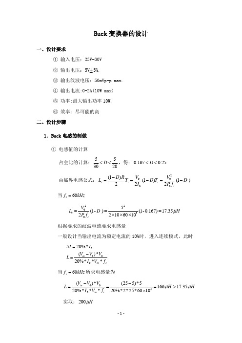
④ 线径的选择
1 I max I 0 I 2.2( A) 2 1 I min I 0 I 1.8( A) 2 D 2 2 I rms ( I max I min I min * I max ) 0.896( A) 3
根据有效值在英美导线规格中,选用 AWG22 线,通过的电流为 1.465A ⑤ 磁芯饱和的验证
依 f s 60kHz ,
2.电容的计算与选择 因 I 20%* I0 0.2*2 0.4( A) 由电容公式: C
I L * T 8* V0
实取: 4.7 F ,10V 的电解电容。 当 f s 60kHz
C
I L * T 0.4 2.23 F 8* V0 8*5*5%*60 103
实取: 200 H
-1-
② 铁芯型号的选择 选择铁硅铝铁芯,型号为 CS166125 ③ 线圈圏数计算
由公式: L N 2 AL 103 ( H ), AL为 nH 可得匝数: N
N2
,
L 200 52.7(匝) ,取 53 匝。 3 N AL 10 72 103
二极管的耐流值: 0.896 0.896*30% 1.165( A) 二极管的耐压值: 30 30*30% 39(V ) 取肖特基整流二极管:STPS3L6OQ-3A,60V MOSFET 的耐流值: 0.896 0.896*30% 1.165( A)
-3-
MOSFET 的耐压值: 30 30*30% 39(V ) 取 N 沟道 MOSFET 管:STP60N55F3-80A,55V 4.UC3842 外围参数计算与选择 ① 晶振电阻和电容的计算 为了方便以后的调试取最大占空比为 0.5 当 f s 60kHz 取 R T=680 ,由 CT=
buck电路基本原理与计算
buck电路基本原理与计算
Buck电路是一种非隔离型的降压转换器,用于将输入电压降
低到输出电压。
它由一个功率开关、一个能量储存元件(电感或电容)、一个输出滤波元件和一个控制电路组成。
Buck电路基本原理:当功率开关关闭时,电感储能,同时根
据Kirchhoff电流定律,电流在电感中保持稳定。
当功率开关
打开时,电感释放储存的能量,驱动输出负载工作,同时根据Kirchhoff电压定律,电压在负载中保持稳定。
通过不断重复
这个开关周期,在输入电压和输出电压之间建立合适的电压差,实现电压降低的目的。
Buck电路计算方法:根据电路原理,可以采用以下计算方法:
1. 根据输出电压和输出电流的需求,确定输出功率。
2. 根据输入电压和输出电压的范围,确定电路的转换比,即D (占空比)=输出电压/输入电压。
D的值一般小于1。
3. 根据功率的转换效率(通常在85~95%之间),计算出输
入功率,即输入功率=输出功率/转换效率。
4. 根据输入电压和输入功率,计算出输入电流,即输入电流=
输入功率/输入电压。
5. 根据电路的输出滤波元件和负载的特性,确定电感或电容元件的额定值和参数。
需要注意的是,Buck电路的设计还需要考虑输入电压和输出
电流的波动、开关频率、功率开关器件的特性等因素,以确保电路的稳定性和可靠性。
BUCK电感计算公式

BUCK电感计算公式
在计算BUCK电感的数值时,我们需要考虑以下几个要素:输入电压(Vin)、输出电压(Vout)、输出电流(Iout)、周期时间(T)和电感元件的压降(ΔV)。
首先,我们需要根据工作原理得出电感电流I_L的表达式。
在BUCK 拓扑中,开关管导通的时间总是小于非导通的时间,即表达式为:Ton = kT, Toff = (1-k)T
其中Ton为导通时间,Toff为非导通时间,k为开关管导通时间与周期时间T之比。
然后,根据电感元件的工作原理,得出电感电流I_L的表达式:
I_L = (Vin – Vout)T / L
接下来,我们需要求解电感元件的压降ΔV。
由于电感元件在电流变化时会产生电压,我们可以得出ΔV与电感电流I_L之间的关系:ΔV = (Iout – I_L) * T / 2
最后,我们可以得出计算BUCK电感数值的公式:
L = (Vin –Vout) * T / (ΔV*2)
根据以上公式,我们可以计算出满足BUCK电路要求的电感数值。
需要注意的是,计算出的电感数值只是一个初步的参考值,实际应用时还需要考虑一些其他因素,如电感元件的可获取性、能量转换效率等。
此外,需要强调的是,BUCK电路中电感的选择和设计往往会涉及一定的电流脉冲和功耗计算,为了确保电路的稳定性、可靠性和高效性,我
们还需要进一步细化计算,进行参数匹配和优化。
因此,以上所述的公式只是电感计算的基础,在实际应用中还需要根据具体需求进行进一步调整和优化。
BOOST电感、BUKC电感、逆变电容、电感计算表
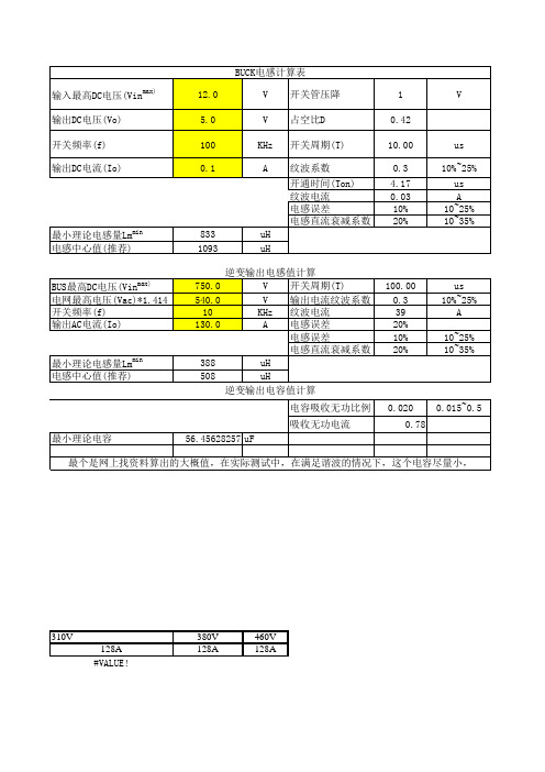
开通时间(Ton) 28.00 纹波电流 80 电感误差 10% 电感直流衰减系数 20% 最小理论电感量Lmmin 电感中心值(推荐) 189 248 uH uH
100 80 60 40
20 20 20 20 10 10
100.00 0.3 39 20% 10% 20%
us 10%~25% A 10~25% 10~35%
0.020 0.78
0.015~0.5
最小理论电容
56.45628257 uF
最个是网上找资料算出的大概值,在实际测试中,在满足谐波的情况下,这个电容尽量小,
310V 128A #VALUE!
380V 128A
BUS最高DC电压(Vin 电网最高电压(Vac)*1.414 开关频率(f) 输出AC电流(Io)
max)
最小理论电感量Lmmin 电感中开关周期(T) 540.0 V 输出电流纹波系数 10 KHz 纹波电流 130.0 A 电感误差 电感误差 电感直流衰减系数 388 uH 508 uH 逆变输出电容值计算 电容吸收无功比例 吸收无功电流
460V 128A
boost电感计算表 输出最高DC电压(Vo) 输入DC电压(Vinmin) 开关频率(f) 输出DC电流(Io) 750.0 540.0 10 160.0 V V KHz A 占空比D 开关周期(T) 纹波系数 0.28 100.00 0.5 us 10%~25% us A 10~25% 10~35%
- 1、下载文档前请自行甄别文档内容的完整性,平台不提供额外的编辑、内容补充、找答案等附加服务。
- 2、"仅部分预览"的文档,不可在线预览部分如存在完整性等问题,可反馈申请退款(可完整预览的文档不适用该条件!)。
- 3、如文档侵犯您的权益,请联系客服反馈,我们会尽快为您处理(人工客服工作时间:9:00-18:30)。
4. Determine wire size
a). Chinese method
φ := 1.13⋅ I J
Where: φ---diameter of wire in mm J---current density (7~16 for typical application)
As := 2.79
AWG21
Ω := 12.77
Ω
1000ft
DCR := MLT⋅ N ⋅Ω
DCR = 5.43
mΩ
2.54⋅12
Pcu := Io2⋅DCR
Pcu = 229.408
Because the inductor was designed in continued mode, the AC resisitance can be ignored.
c) Temperature ∆τ := 0.833 Pt As Where: Pt is the total loss in mW As is the surface area in cm^2 Note: This method just for reference, the best way is to build a sample to test.
1). Verify if the core saturation ∆B := ∆I⋅ L⋅10− 2 N⋅Ae
Where: ∆B is the flux swing in Tesla ∆I is the peak to peak current L is inductance in µH N is number of turns Ae is core cross area in cm^2
N := Lmin⋅ 103
0.5
N = 8.913 N := 9
AL⋅0.935
Actually, the inductance will be about 1.06uH at 9 turns.
4. determine wire size Assume: J := 13
φ := 1.13⋅ Io J
Use maximum voltage cross coil to calculate core loss. Here:
Vpk := Vin − Vo
∆B := Vpk⋅ D⋅108 2⋅Ae⋅N⋅f
∆B = 86.806 G
For -8 matrerial: the relationship between loss and AC flux & frequency can be gotten from core catalog.
N := [L⋅(Rc + Rg)]0.5
Where: L ---inductance in Henry Rc---Magnetic resistance of core Rg---Magnetic resistance of air gap
Rc := le µ⋅Ae
Rg := lg µo⋅Ae
Where: le---effective length of core in meter Ae---cross area of core in square meter lg---gap length in meter
2. Choose the core and material: chosse -8 material for frequency requirement.
W := 0.5Lmin⋅Io2
W = 21.968
Go to core selection cure and chart:
Found that T30 will yield such energy with single winding. The ampere turns will be about 67. So the pri-turns will be 10.
2. Choose core (Ferrite core design)
1). Calculate the energy storage W := L⋅I2
2). Choose the core and determine the gap based on energy vs air-gap curve
Buck inductor design
---Prepared by Bean
1. Calculate inductance:
1). Determine Duty cycle
D := Vo Vin
2). Calculate inductance
Analysing the circuit, we can get the followed equations easily.
a). Continued mode
L := (Vin − Vo)⋅ D
or
2Kf ⋅f ⋅Io
L := Vo⋅ (1 − D) 2Kf ⋅f ⋅Io
Where: Vin is input voltage (V)
Vo is output voltage (V)
f is operation frequency (Hz) Io is output current (A)
P :=
f
+ 2.5⋅10− 14⋅∆B2⋅f 2
1.9⋅109 + 2⋅108 + 9⋅105
∆B3
∆B2.3 ∆B1.65
P = 284.252
Pcore := P⋅Ve
Pcore = 31.268
Pt := Pcu + Pcore ∆τ := Pt 0.833
As
Pt = 260.675
∆τ = 43.795
Energy (J)
0.1
12
air gap (mm)
3. Calculate the number of turns:
From step 2, the core and gap length were determined. Now we can use related factors of core to calculate turns number.
b). American method
CM := J⋅I
Where: CM---Area in circular mils J---current density (100~250 for typical application)
Then go to wire table to find right wire.
The flux swing divided by 2, then go to the core loss curve and find the core loss. If the core loss higher than 100mW/cm^3, the core is saturation. *This rule come from Lloyd's technical paper. Actually, if you choose the core and gap based on this method, the core don't want to saturate.
Ae := 0.06 le := 1.84 Np := 10 AL := 14 Ve := .11
3. Adjust turns
Magnetizing force: H := 0.4⋅π⋅Np⋅ Io le
H = 44.392
Then go to µ% vs H cure and find the µ% is 93.5%.
2. high ac loss 3. EMI problem Powder:1. high core loss 2. high saturation flux density 3. soft bias performance
Buck: Input voltage: 5V Output voltage: 1.25V Output current: 6.5A Frequency: 1MHz
Kf is the ripple factor (0.1~0.2 for typical application)
b). Discontinued mode
L := (Vi
L := Vo⋅ (1 − D) f ⋅Ipk
Note: The diode need to be considered on some cases especially for low output voltage application.
Vin := 5 Vo := 1.25 Io := 6.5 f := 1000000
1. Calculate duty cycle and inductance (Normally, the buck inductor is designed to continued mode
D := Vo Vin
2). Temperature rise a). copper loss Pcopper := Idc2⋅Rdc + Iac2⋅Rac Where: Idc is DC current Rdc is direct current risistance Iac is effective value of AC current Rac is AC risistance can got from Dewll's curve
References: [1] Lloyd H.Dixon: Unitrode Magnetics Design Handbook [2] Micrometals Catalog, 2000 [3] Ferroxcube Catalog, 2002
