【Fluent案例】:沸腾
Fluent验证案例67:临界热流管内沸腾
2.9 Initialization
鼠标右键选择模型树节点Initialization,点击弹出菜单项Initialize开始初始化
2.10 Run Calculation
双击模型树节点Run Calculation,右侧面板设置Number of Iterations为6000,点击按钮Calculate开始计算
3 计算结果
中间某段气相分布
模型长宽比太大,不便于观察,这里取中间一段来观察气相分布。
壁面温度分布
https:///s/1SFUQCoxzBCGSVUv_R803rA
提取码:vq9l
鼠标双击模型树节点Models > Multiphase > Phase > Secondary Phase,弹出对话框中设置water-vapor为主相,并修改名称为vapor,设置Diameter为boiling-dia
鼠标双击模型树节点Models > Multiphase >Phase Interactions,弹出对话框中进入Mass标签页,如下图所示进行设置
鼠标双击模型树节点modelsviscous弹出的模型设置对话框中选择rngkepsilon湍流模型选择选项nonequilibriumwallfunctions如下图所示
Fluent验证案例67:临界热流管内沸腾
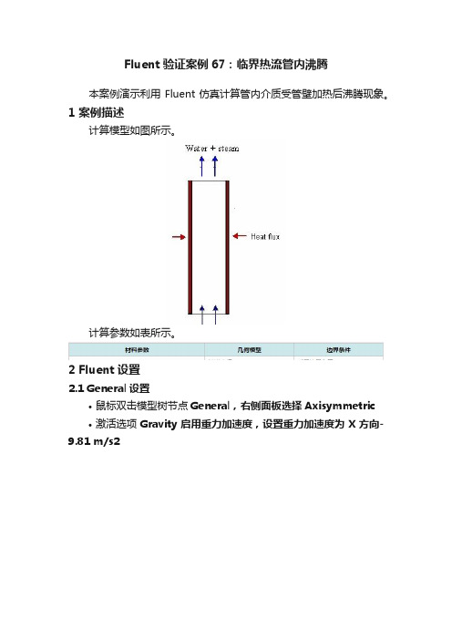
本案例演示利用Fluent仿真计算管内介质受管壁加热后沸腾现象。
1 案例描述
计算模型如图所示。
点击Eidt…按钮进入沸腾模型设置对话框,如下图所示进行参数设置
2.6 Boundary Conditions
1、mass-flow-inlet-7
基于Fluent中DPM的水滴蒸发冷凝和沸腾过程中传热传质的规律和程序实现

基于Fluent中DPM的水滴蒸发冷凝和沸腾过程中传热传质的规律和程序实现Fluent是一款流体动力学软件,其中包含了离散相方法(DPM)用于模拟颗粒的运动和传热传质过程。
水滴的蒸发、冷凝和沸腾过程都是与传热传质密切相关的现象。
本文将介绍基于Fluent中DPM的水滴蒸发、冷凝和沸腾过程中的传热传质规律以及相应的程序实现。
1.水滴的蒸发过程:水滴在蒸发过程中,会受到环境中的热量传递,水分子在水滴内部形成蒸汽,并从水滴表面逐渐蒸发。
蒸发过程中的传热传质可以通过Fluent中DPM模型来模拟。
首先,需要构建一个包含水滴颗粒和气体介质的计算域。
水滴颗粒的初始位置、粒径和质量可以根据实际情况进行设定。
其次,通过设定水滴颗粒的表面属性,如温度、蒸汽质量分数等,来模拟水滴的蒸发过程。
可以通过设定边界条件或者设置适当的物理模型来实现。
针对传热传质规律,可以使用DPM中的蒸发模型。
该模型基于物理机理,考虑了水滴表面温度、湿度、传热参数以及气体介质中水分浓度梯度等因素,通过数值方法求解蒸发过程中的能量和质量传递方程。
2.水滴的冷凝过程:水滴在冷凝过程中,会释放热量给周围环境,水蒸气在与冷凝表面接触时变成液体。
冷凝过程中的传热传质可以同样通过Fluent中DPM模型来模拟。
与水滴蒸发相反,冷凝过程需要考虑水滴颗粒与冷凝表面间的传热传质。
可以通过设定边界条件或者设置适当的物理模型来实现。
针对传热传质规律,可以使用DPM中的冷凝模型。
该模型同样基于物理机理,考虑了水滴表面温度、湿度、传热参数以及冷凝表面与水滴颗粒的接触区域等因素,通过数值方法求解冷凝过程中的能量和质量传递方程。
3.水滴的沸腾过程:水滴在沸腾过程中,会迅速产生蒸汽,并从液态转化为气体态。
沸腾过程中的传热传质也可以通过Fluent中DPM模型来模拟。
为模拟水滴的沸腾过程,需要考虑水滴颗粒的表面属性、液相和气相的传热传质过程。
可以通过设定边界条件或者设置适当的物理模型来实现。
9.5.5 求解设置:沸腾流[共9页]
![9.5.5 求解设置:沸腾流[共9页]](https://img.taocdn.com/s3/m/2c0b47ff4b73f242326c5f48.png)
532精通CFD 工程仿真与案例实战—— FLUENT GAMBIT ICEM CFD Tecplot(第2版)(c )在Surfaces 中选择outlet 。
(d )单击Plot ,关闭Solution XY Plot 面板。
(6)导出出口位置的数据,如图9-49所示。
File/Write/Profile…(a )在Options 中Define New Profile 。
(b )在Surfaces 中选择outlet 。
(c )在V alues 中选择V elocity Magnitude 、Turbulence Kinetic Energy (k)和Turbulent Dissipation Rate (Epsilon)。
(d )单击Write…打开Select File 面板。
(e )在File Name 一栏输入liquid-outlet.prof ,单击OK 。
(f )关闭Write Profile 面板。
(7)读入profile 文件。
File/Read/Profile…(8)保存工况和数据文件(boiling-single-phase.cas.gz 和boiling-single-phase.dat.gz )。
9.5.5 求解设置:沸腾流步骤一:模型(1)选择非定常求解器。
Define/Models/Solver(2)勾选Eulerian 多相流模型,如图9-50所示。
Define/Models/Multiphase… (a )在Model 中选择Eulerian 。
(b )将Number of Phases 设置为2。
(c )单击OK ,关闭Multiphase Model 面板。
(3)确保k-epsilon Multiphase Model 中选择Mixture 。
Define/Models/Viscous步骤二:编译UDF(1)编译UDF ,UDF 文件名为boiling-rpi-model.c 。
FLUENT水沸腾模拟
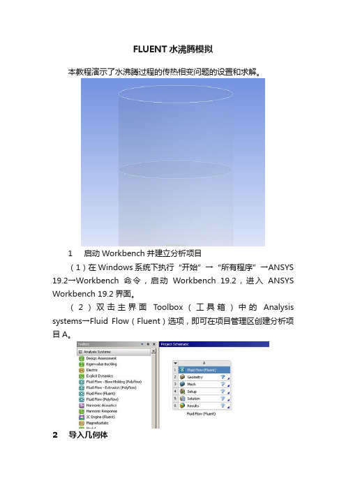
FLUENT水沸腾模拟本教程演示了水沸腾过程的传热相变问题的设置和求解。
1 启动Workbench并建立分析项目(1)在Windows系统下执行“开始”→“所有程序”→ANSYS 19.2→Workbench命令,启动Workbench 19.2,进入ANSYS Workbench 19.2界面。
(2)双击主界面Toolbox(工具箱)中的Analysis systems→Fluid Flow(Fluent)选项,即可在项目管理区创建分析项目A。
2 导入几何体(1)在A2栏的Geometry上单击鼠标右键,在弹出的快捷菜单中选择Import Geometry→Browse命令,此时会弹出“打开”对话框。
(2)在弹出的“打开”对话框中选择文件路径,导入几何体文件。
3 划分网格(1)双击A3栏Mesh项,进入Meshing界面,在该界面下进行模型的网格划分。
(2)右键分别选择水罐的加热壁面,水罐壁面和出口,在弹出的快捷菜单中选择Create Named Selection,弹出Selection Name对话框,输入名称wall_heat,wall_tank和outlet,单击OK按钮确认。
(3)同步骤(2)选择水区域和空气区域,分别命名为fluid_water和fluid_air。
(4)网格参数设置,在Element Size中输入8mm,在Quality 中,Smoothing选择High。
(5)右键单击模型树中Mesh选项,选择快捷菜单中的Generate Mesh选项,开始生成网格。
(6)网格划分完成以后,单击模型树中Mesh项可以在图形窗口中查看网格。
(7)执行主菜单File→Close Meshing命令,退出网格划分界面,返回到Workbench主界面。
(8)右键单击Workbench界面中A3 Mesh项,选择快捷菜单中的Update项,完成网格数据往Fluent分析模块中的传递。
4 设置材料(1)双击A4栏Setup项,打开Fluent Launcher对话框,单击OK按钮进入FLUENT界面。
fluent 水沸腾相变UDF

}
else
{
m_dot_v
=
fabs(T_SAT-C_T(cell,mix_th))/T_SAT;
-0.1*C_VOF(cell,
sec_th)*C_R(cell,
sec_th)*
相失
//如果指向混合区的单元温度小于蒸发温度,气相向液相的质量转移,气
dS[eqn] = -0.1*C_R(cell, sec_th)* fabs(C_T(cell, mix_th) - T_SAT)/T_R(cell, pri_th)*fabs(C_T(cell, mix_th) - T_SAT)/T_SAT; //定义源项对质量 转移偏导
}
else
{
m_dot_l = 0.1*C_VOF(cell, sec_th)*C_R(cell, sec_th)* fabs(T_SAT-C_T(cell,mix_th))/T_SAT; //如果指向混合区液相的单元温度小于蒸发温度,气相
向液相的质量转移,液相得
移的偏导为零
dS[eqn] = 0.;//由于是气相向液相转移,所以液相的质量源项对质量转
}
return m_dot_l;
}
DEFINE_SOURCE(vap_src, cell, sec_th, dS, eqn) //气相质量源项 UDF
{
Thread * mix_th, *pri_th;
不为零
//由于是气相向液相转移,所以气相的质量源项对自身的质量转移的偏导
}
return m_dot_v;
}
DEFINE_SOURCE(enrg_src, cell, mix_th, dS, eqn) //混合模型能量源项 UDF
{
基于Fluent中DPM的水滴蒸发冷凝和沸腾过程中传热传质的规律和程序实现

基于Fluent中DPM的水滴蒸发冷凝和沸腾过程中传热传质的规律和程序实现基于Fluent中DPM的水滴蒸发、冷凝和沸腾过程中传热传质的规律和程序实现0 引言本文将详细讲述基于Fluent软件中DPM的水滴蒸发、冷凝和沸腾的控制方程和程序实现。
在包含水滴的多相流中(离散相和连续相)水滴(离散相)会和湿空气(连续相)发生传热传质。
对于传热过程,包括湿空气和水滴表面的对流换热和水滴蒸发和沸腾时的相变热。
对于传质过程,包括湿空气中水蒸气在液滴上冷凝,液滴的蒸发和沸腾。
请注意,在本文中,湿空气中的水只能在水滴上冷凝,不能在没有水滴的情况下生成水滴,且传热过程中不考虑辐射换热并假设液滴的温度试均匀的。
本文最后提供的程序仅适用于ANSYS19.1及其兼容版本。
为了统一词汇,湿空气(连续相)中的组成成分将表示为“组分(species)”,液滴(离散相)中的组成成分将表示为“成分(component)”。
1 传热液滴和湿空气的传热主要体现在两方面,一方面是液滴与湿空气之间的对流换热,另一方面是液滴和湿空气之间发生传质时的换热。
下式中,等号右侧第一项为对流换热热量,第二项为传质换热量。
m p c p dT pdt=?A p(T∞?T p)?dm pdtfg1.1对流换热湿空气和液滴之间的对流换热遵循牛顿冷却定律。
液滴与湿空气之间的对流换热流量用下式表示:m p c p dT p=?A p(T∞?T p)式中:m p:液滴(离散相)的质量,kg;c p:液滴的比热容,J/kg?K?1;T p:滴液的温度,K;:对流换热系数,W/m2?K?1;A p:颗粒表面积,A p=πd p2,m2;d p:颗粒直径,m;T∞:湿空气的温度,K。
上式中对流换热系数由湿空气和液滴之间的努塞尔数计算得到,液滴和湿空气之间的努塞尔数由下式给出:Nu=?d pk=2+0.6×Re12×Pr13式中:k:湿空气的导热系数,W/m?K?1;Re:雷诺数;Pr:湿空气的普朗特数,Pr=μc pk。
fluent沸腾案例

Tutorial:Heat and Mass Transfer with the Mixture Model and Evaporation-Condensation ModelIntroductionThe purpose of this tutorial is to demonstrate the solution of a multiphase problem involv-ing heat and mass transfer using the mixture multiphase model along with Evaporation-Condensation model.This tutorial demonstrates how to do the following:•Use the mixture model in ANSYS FLUENT to solve a mixture multiphase problem.•Use Evaporation-Condensation model•Solve the case using appropriate solver settings.•Postprocess the resulting data.PrerequisitesThis tutorial is written with the assumption that you have completed Tutorial1from the ANSYS FLUENT13.0Tutorial Guide,and that you are familiar with the ANSYS FLUENT navigation pane and menu structure.Some steps in the setup and solution procedure will not be shown explicitly.In this tutorial you will use the mixture multiphase model.This tutorial will not cover the mechanics of using this model.Instead,it will focus on the application of the model to solvea mixture multiphase problem involving heat and mass transfer.For more information referto Section26.4Setting Up the Mixture Model in the ANSYS FLUENT13.0User’s Guide.Problem DescriptionThe problem to be solved in this tutorial is shown in Figure1.Initially,the container contains water(the primary phase)at a temperature near the boiling point(372K).The center portion of the bottom wall of the container is at a temperature of573K,which is higher than the boiling temperature.Because of conduction,the temperature of thefluid near this wall will increase beyond the saturation temperature(373K).Vapor bubbles will form and rise due to buoyancy,establishing a pattern similar to a bubble column with vapor escaping at the top and water recirculating in the container.Heat and Mass Transfer with the Mixture ModelFigure1:Problem SpecificationPreparation1.Copy the meshfile(boil.msh.gz)to the working folder.e FLUENT Launcher to start the2D version of ANSYS FLUENT.For more information about FLUENT Launcher see Section1.1.2Starting ANSYS FLU-ENT Using FLUENT Launcher in the ANSYS FLUENT13.0User’s Guide.3.Enable Double-Precision in the Options list.Note:The Display Options are enabled by default.Therefore,after you read in the mesh,it will be displayed in the embedded graphics window.Setup and SolutionStep1:Mesh1.Read the meshfile boil.msh.gz.File−→Read−→Mesh...Step2:General1.Check the mesh.−→CheckHeat and Mass Transfer with the Mixture ModelFigure2:Mesh DisplayANSYS FLUENT will perform various checks on the mesh and will report the progress in the console.Ensure that the minimum volume reported is a positive number.2.Enable the transient solver by selecting Transient from the Time list.−→TransientStep3:Models1.Define the multiphase model.−→Multiphase−→Edit...Heat and Mass Transfer with the Mixture Model(a)Select Mixture from the Model list.(b)Enable Implicit Body Force from the Body Force Formulation list.(c)Click OK to close the Multiphase Model dialog box.2.Enable energy equation.−→−→Edit...After you enable the Energy Equation an information dialog box will open remindingyou to confirm the property values that have changed.Step4:Materials1.Copy water-liquid(h2o<l>from the database.(a)Click the FLUENT Database...to open the FLUENT Database Materials dialogbox.i.Select water-liquid(h2o<l>)from the FLUENT Fluid Materials selection list.ii.Click Copy and close the FLUENT Database Materials dialog box.Heat and Mass Transfer with the Mixture Model(b)Enter1000kg/m3for Density.(c)Enter0.0009kg/m-s for Viscosity.(d)Enter18.0152for Molecular Weight.(e)Enter0for Standard State Enthalpy.(f)Enter298.15K for Reference Temperature.(g)Click Change/Create and and close Create/Edit Materials dialog box.2.Copy water-vapor(h2o from the database.(a)Click the FLUENT Database...to open the FLUENT Database Materials dialogbox.i.Select water-vapor(h2o)from the FLUENT Fluid Materials selection list.ii.Click Copy and close the FLUENT Database Materials dialog box.Heat and Mass Transfer with the Mixture Model(b)Enter0.5542kg/m3for Density.(c)Enter2014j/kg-K for Cp(Specific Heat).(d)Enter0.0261w/m-K for Thermal Conductivity.(e)Enter1.34e-05kg/m-s for Viscosity.(f)Enter18.0152for Molecular Weight.(g)Enter2.992325e+07for Standard State Enthalpy.(h)Enter298.15K for Reference Temperature.(i)Click Change/Create and close the Create/Edit Materials dialog box.Note that the standard state enthalpies of vapor and liquid phase are set such that theirdifference equals to latent heat of vaporization.The unit of standard state enthalpy iskj/kmol and usually the latent heat value is avaiable in kj/kg.while specifying it here,multiply that value by molecular wight.For correct specification of latent heat it is important to set the reference temperatureto298.15KHeat and Mass Transfer with the Mixture Model Step5:Phases1.Define the primary phase.−→−→Edit...(a)Enter liquid for Name.(b)Select water-liquid from the Phase Material drop-down list.(c)Click OK to close the Primary Phase dialog box.2.Define the secondary phase.−→phase-2−→Edit...(a)Enter vapor for Name.(b)Ensure that air is selected from the Phase Material drop-down list.Heat and Mass Transfer with the Mixture Model(c)Enter0.0002m for Diameter.(d)Click OK to close the Secondary Phase dialog box.3.Select the Evaporation-Condensation Model−→Interaction...(a)Click the Mass tab.(b)Select liquid from the From Phase drop-down list.(c)Select vapor from the To Phase drop-down list.(d)Select evaporation-condensation from the Mechanism drop-down list and Click theEdit...button for Evaporation-Condensation to open the Evaporation-Condensationdialog box.Heat and Mass Transfer with the Mixture Model(e)Click OK to close the Evaporation-Condensation dialog box.(f)Click OK to close the Phase Interaction dialog box.Step6:Cell Zone Conditions−→1.Select mixture from the Phase drop-down list and click the Edit...button to open theFluid dialog box.2.Keep the default settings and Click OK to close thefluid panel.Step7:Boundary Conditions1.Set the boundary conditions for the pressure outlet.Conditions...−→poutlet(a)Select mixture from the Phase drop-down list and click the Edit...button to openthe Pressure Outlet dialog box.Heat and Mass Transfer with the Mixture Modeli.Retain the default value of0for the Gauge Pressure.ii.Click on Thermal tab and enter372K as the Backflow Total Temperature.iii.Click OK to close the Pressure Outlet dialog box.(b)Select vapor from the Phase drop-down list and click the Edit...button to openthe Pressure Outlet dialog box.i.Click on the Multiphase tab.ii.Retain the default value of0for the Backflow Volume Fraction.iii.Click OK to close the Pressure Outlet dialog box.2.Set the boundary conditions for the wall zone,(wall-hot).−→(a)Select mixture from the drop-down list for Phase and click the Edit...button toopen the Wall dialog box.i.Click the Thermal tab and select Temperature from the Thermal Conditionslist.ii.Enter573K for Temperature.iii.Click OK to close the Wall dialog box.3.Set the boundary conditions for the adiabatic wall,wall-1.Conditions...−→wall-1−→Edit(a)Click on Thermal tab.(b)Retain the default value of0for Heat Flux to specify an adiabatic wall.(c)Click OK to close the Wall dialog box.4.Similarly check for the other adiabatic wall,wall-2.−→−→EditStep8:Operating Conditions−→Operating Conditions...1.Enable Gravity.2.Enter-9.81m/s2for Gravitational Acceleration in the Y direction.3.Enable Specified Operating Density.4.Enter0.5542kg/m3for Operating Density.5.Click OK to close the Operating Conditions dialog box.Step9:Solution1.Set the solution control parameters.(a)Select Green Gauss Cell Based from the Gradient drop-down list.(b)Select Body Force Weighted from the Pressure drop-down list.(c)Select QUICK from the Momentum,Volume Fraction,and Energy drop-down lists.2.Set the Under-Relaxation Factors.(a)Enter0.5for Pressure.(b)Enter0.2for Momentum.(c)Enter0.4for Volume Fraction.3.Initialize theflowfield using a Temperature of372k.−→Initialize4.Mark the boundary region next to wall-hot.Adapt−→Boundary...(a)Retain the Number of Cells as1.(b)Deselect all zones from the Boundary Zones selection list,and then select wall-hot.(c)Click Mark to mark the cells for refinement.(d)Close the Boundary Adaption dialog box.5.Patch a temperature slightly higher than the saturation temperature of373K.Initialization−→Patch...(a)Select Temperature from the Variable selection list.(b)Enter373.15K for Value.(c)Select boundary-r0from the Registers To Patch selection list.(d)Click Patch and close the Patch dialog box.6.Save datafiles every100time steps.(a)Enter100for Autosave Every(Time Steps).7.Define commands for setting up animations.(Execute Commands)−→Create/Edit...(a)Set Defined Commands to5.(b)Enable Active for all5commands.(c)Set Every for all commands to10.(d)Select Time Step from the When drop-down lists for all commands.(e)Enter the commands as shown in the table.Name Commandcommand-1dis con vap vof00.1command-2dis view r-v front"command-3dis s-p vof%06t.jpgcommand-4dis vec li vel li vm00.4,,command-5dis s-p vel%06t.jpg(f)Click OK to close the Execute Commands dialog box.8.Start the calculation.Run Calculation(a)Enter0.01as the Time Step Size.(b)Enter1000for Number of Time Steps.(c)Save the initial case and datafiles(boil-init.cas.gz and boil-init.dat.gz).File−→Write−→Case&Data...(d)Click Calculate.9.Save the case and datafiles(boil.cas.gz and boil.dat.gz).Step10:Postprocessing1.Read the datafile for the300th time step(boil-1-00300.dat).File−→Read−→Data...2.Displayfilled contours of liquid velocity magnitude(Figure3).−→−→Set Up...(a)Select Filled from the Options list.(b)Select Velocity...and Velocity Magnitude from the Contours of drop-down lists.(c)Select liquid from the Phase drop-down list and click Display.Figure3:Contours of liquid Velocity Magnitude3.Displayfilled contours of vapor volume fraction(Figure4).(a)Select Phases...and Volume fraction from the Contours of drop-down lists.(b)Select vapor from the Phase drop-down list and click Display.Figure4:Contours of vapor Volume Fraction4.Displayfilled contours of static pressure(Figure5).(a)Select Pressure...and Static Pressure from the Contours Of drop-down lists andclick Display.Figure5:Contours of Static Pressure5.Displayfilled contours of static temperature(Figure6).(a)Select Temperature...and Static Temperature from the Contours of drop-downlists.(b)Disable Auto Range and enable Clip to Range from the Options list.(c)Enter372K for Min and375K for Max.(d)Click Display.Figure6:Contours of Static TemperatureSummaryApplication of the mixture multiphase model along with Evaporation-Condensation model has been demonstrated in this tutorial.。
(精品)fluent 水沸腾相变UDF
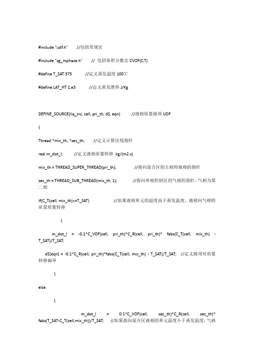
#include "udf.h" //包括常规宏#include "sg_mphase.h" // 包括体积分数宏CVOF(C,T)#define T_SAT 373 //定义蒸发温度100℃#define LAT_HT 1.e3 //定义蒸发潜热J/KgDEFINE_SOURCE(liq_src, cell, pri_th, dS, eqn) //液相质量源项UDF{Thread *mix_th, *sec_th; //定义计算区线指针real m_dot_l; //定义液相质量转移kg/(m2.s)mix_th = THREAD_SUPER_THREAD(pri_th); //指向混合区的主相即液相的指针sec_th = THREAD_SUB_THREAD(mix_th, 1); //指向单相控制区的气相的指针,气相为第二相if(C_T(cell, mix_th)>=T_SAT) //如果液相单元的温度高于蒸发温度,液相向气相的质量质量转移{m_dot_l = -0.1*C_VOF(cell, pri_th)*C_R(cell, pri_th)* fabs(C_T(cell, mix_th) - T_SAT)/T_SAT;dS[eqn] = -0.1*C_R(cell, pri_th)*fabs(C_T(cell, mix_th) - T_SAT)/T_SAT; //定义源项对质量转移偏导}else{m_dot_l = 0.1*C_VOF(cell, sec_th)*C_R(cell, sec_th)* fabs(T_SAT-C_T(cell,mix_th))/T_SAT; //如果指向混合区液相的单元温度小于蒸发温度,气相向液相的质量转移,液相得dS[eqn] = 0.;//由于是气相向液相转移,所以液相的质量源项对质量转移的偏导为零}return m_dot_l;}DEFINE_SOURCE(vap_src, cell, sec_th, dS, eqn) //气相质量源项UDF{Thread * mix_th, *pri_th;real m_dot_v;mix_th = THREAD_SUPER_THREAD(sec_th); //指向混合区的第二相即气相的指针pri_th = THREAD_SUB_THREAD(mix_th, 0); 指向单相控制区的液相的指针,液相为主相if(C_T(cell, mix_th)>=T_SAT) //如果混合区单元的温度高于蒸发温度,液相向气相的质量质量转移{m_dot_v = 0.1*C_VOF(cell, pri_th)*C_R(cell, pri_th)*fabs(C_T(cell, mix_th) - T_SAT)/T_SAT;dS[eqn] = 0.;‘由于是液相向气相转移,所以气相的质量源项对来自液相的质量转移的偏导为零}else{m_dot_v = -0.1*C_VOF(cell, sec_th)*C_R(cell, sec_th)* fabs(T_SAT-C_T(cell,mix_th))/T_SAT;//如果指向混合区的单元温度小于蒸发温度,气相向液相的质量转移,气相失dS[eqn] = -0.1*C_R(cell, sec_th)* fabs(C_T(cell, mix_th) - T_SAT)/T_SAT;//由于是气相向液相转移,所以气相的质量源项对自身的质量转移的偏导不为零}return m_dot_v;}DEFINE_SOURCE(enrg_src, cell, mix_th, dS, eqn) //混合模型能量源项UDF{Thread *pri_th, *sec_th;real m_dot;pri_th = THREAD_SUB_THREAD(mix_th, 0);//指向混合区的液相的指针sec_th = THREAD_SUB_THREAD(mix_th, 1); //指向混合区的气相的指针if(C_T(cell, mix_th)>=T_SAT) //如果混合区的单元温度高于蒸发温度。
fluent沸腾案例.pdf
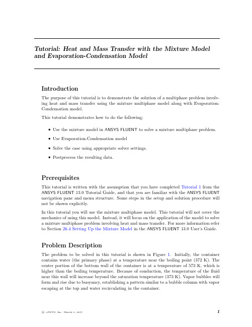
Tutorial:Heat and Mass Transfer with the Mixture Model and Evaporation-Condensation ModelIntroductionThe purpose of this tutorial is to demonstrate the solution of a multiphase problem involv-ing heat and mass transfer using the mixture multiphase model along with Evaporation-Condensation model.This tutorial demonstrates how to do the following:•Use the mixture model in ANSYS FLUENT to solve a mixture multiphase problem.•Use Evaporation-Condensation model•Solve the case using appropriate solver settings.•Postprocess the resulting data.PrerequisitesThis tutorial is written with the assumption that you have completed Tutorial1from the ANSYS FLUENT13.0Tutorial Guide,and that you are familiar with the ANSYS FLUENT navigation pane and menu structure.Some steps in the setup and solution procedure will not be shown explicitly.In this tutorial you will use the mixture multiphase model.This tutorial will not cover the mechanics of using this model.Instead,it will focus on the application of the model to solvea mixture multiphase problem involving heat and mass transfer.For more information referto Section26.4Setting Up the Mixture Model in the ANSYS FLUENT13.0User’s Guide.Problem DescriptionThe problem to be solved in this tutorial is shown in Figure1.Initially,the container contains water(the primary phase)at a temperature near the boiling point(372K).The center portion of the bottom wall of the container is at a temperature of573K,which is higher than the boiling temperature.Because of conduction,the temperature of thefluid near this wall will increase beyond the saturation temperature(373K).Vapor bubbles will form and rise due to buoyancy,establishing a pattern similar to a bubble column with vapor escaping at the top and water recirculating in the container.Heat and Mass Transfer with the Mixture ModelFigure1:Problem SpecificationPreparation1.Copy the meshfile(boil.msh.gz)to the working folder.e FLUENT Launcher to start the2D version of ANSYS FLUENT.For more information about FLUENT Launcher see Section1.1.2Starting ANSYS FLU-ENT Using FLUENT Launcher in the ANSYS FLUENT13.0User’s Guide.3.Enable Double-Precision in the Options list.Note:The Display Options are enabled by default.Therefore,after you read in the mesh,it will be displayed in the embedded graphics window.Setup and SolutionStep1:Mesh1.Read the meshfile boil.msh.gz.File−→Read−→Mesh...Step2:General1.Check the mesh.−→CheckHeat and Mass Transfer with the Mixture ModelFigure2:Mesh DisplayANSYS FLUENT will perform various checks on the mesh and will report the progress in the console.Ensure that the minimum volume reported is a positive number.2.Enable the transient solver by selecting Transient from the Time list.−→TransientStep3:Models1.Define the multiphase model.−→Multiphase−→Edit...Heat and Mass Transfer with the Mixture Model(a)Select Mixture from the Model list.(b)Enable Implicit Body Force from the Body Force Formulation list.(c)Click OK to close the Multiphase Model dialog box.2.Enable energy equation.−→−→Edit...After you enable the Energy Equation an information dialog box will open remindingyou to confirm the property values that have changed.Step4:Materials1.Copy water-liquid(h2o<l>from the database.(a)Click the FLUENT Database...to open the FLUENT Database Materials dialogbox.i.Select water-liquid(h2o<l>)from the FLUENT Fluid Materials selection list.ii.Click Copy and close the FLUENT Database Materials dialog box.Heat and Mass Transfer with the Mixture Model(b)Enter1000kg/m3for Density.(c)Enter0.0009kg/m-s for Viscosity.(d)Enter18.0152for Molecular Weight.(e)Enter0for Standard State Enthalpy.(f)Enter298.15K for Reference Temperature.(g)Click Change/Create and and close Create/Edit Materials dialog box.2.Copy water-vapor(h2o from the database.(a)Click the FLUENT Database...to open the FLUENT Database Materials dialogbox.i.Select water-vapor(h2o)from the FLUENT Fluid Materials selection list.ii.Click Copy and close the FLUENT Database Materials dialog box.Heat and Mass Transfer with the Mixture Model(b)Enter0.5542kg/m3for Density.(c)Enter2014j/kg-K for Cp(Specific Heat).(d)Enter0.0261w/m-K for Thermal Conductivity.(e)Enter1.34e-05kg/m-s for Viscosity.(f)Enter18.0152for Molecular Weight.(g)Enter2.992325e+07for Standard State Enthalpy.(h)Enter298.15K for Reference Temperature.(i)Click Change/Create and close the Create/Edit Materials dialog box.Note that the standard state enthalpies of vapor and liquid phase are set such that theirdifference equals to latent heat of vaporization.The unit of standard state enthalpy iskj/kmol and usually the latent heat value is avaiable in kj/kg.while specifying it here,multiply that value by molecular wight.For correct specification of latent heat it is important to set the reference temperatureto298.15K。
fluent中的沸腾模型(2)-Non-equilibriumSubcooledBoiling
fluent中的沸腾模型(2)-Non-equilibriumSubcooledBoiling“ 长风破浪会有时,直挂云帆济沧海!”“过冷沸腾”是用来描述这样一种物理情况:即使液体的体积平均温度小于饱和值,但壁温高到足以导致壁上发生沸腾。
在这种情况下,能量直接从壁面传递到液体。
这些能量的一部分会使液体的温度升高,另一部分会产生蒸汽。
相间传热也会导致液体平均温度升高,而饱和蒸汽冷凝。
此外,一些能量可以直接从壁面转移到蒸汽中。
这些基本机制是所谓的伦斯勒理工学院(RPI)模型的基础。
在ANSYS Fluent中,在欧拉多相模型的基础上建立了壁面沸腾模型。
多相流动由相连续性守恒方程、动量守恒方程和能量守恒方程控制。
采用 Kurual 和 Podowski 的RPI形核沸腾模型和Lavieville等人的扩展式对壁面沸腾现象进行了建模。
该壁面沸腾模型适用于三种不同的壁面边界:等温壁面、指定热流和指定传热系数(耦合壁面边界)。
如下面所描述的,已经考虑了动量、质量和热量的界面传递以及沸腾流中的湍流模型。
01—Non-equilibrium Subcooled Boiling当使用基本RPI模型时,蒸汽的温度不计算,而是固定在饱和温度。
为了模拟从核态沸腾状态(DNB)开始的沸腾,或者模拟临界热流量和干燥后的条件,必须包括过程中的蒸汽温度。
现将壁面体热分区修改如下:其中q_c、q_Q、q_E分别为液相对流热通量、淬火热通量和蒸发热通量(详见fluent中的沸腾模型(1)-RPI模型)。
额外的热流通量是q_V表示气相的对流热通量,q_G表示系统中任何其他可能的气相的热通量。
它们可以表示为:与液相的q_C相似,对流换热系数h_V和h_G由壁面函数公式计算。
函数f(α1)依赖于局部液体体积分数,其极限值与液体体积分数相似。
Lavieville等人提出了如下表达式:这里蒸汽分数的临界值是α_l_crit=0.2end后记:本人将毕生致力于CFD,为我国的仿真事业做一点点贡献。
Fluent案例沸腾

【Fluent案例】:沸腾1 介绍本案例的利用Mixture多相流模型以及Evaporation-Condensation模型解决传热与传质问题。
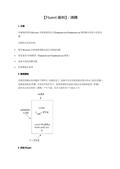
本教程包含的内容:∙使用Mixture多相流模型解决混合多相流问题∙使用蒸发-冷凝模型(Evaporation-Condensation模型)∙选择合适的求解设置∙结果数据后处理2 案例描述本教程要解决的问题如下图所示。
初始状态下,容器中包含有温度接近沸点的水(温度372K),容器底部温度573K,在热传导的作用下,底部壁面附近温度会超过水的饱和温度(373K),此时水会发生相变(沸腾)产生气泡,在浮力的作用下气泡会上升。
3 启动Fluent∙启动Fluent∙选择2D及Double Precision∙选择OK按钮启动Fluent4 读入网格∙利用菜单File → Read → Mesh…读入网格文件Boil.msh5 General设置∙选择模型树节点General∙点击Scale按钮查看计算域尺寸∙点击Check按钮检查网格质量∙可点击Display按钮查看网格6 Multiphase设置这里选用Mixture多相流模型。
∙双击模型树节点Models > Multiphase,弹出多相流设置对话框∙选择Mixture多相流模型∙设置Number of Eulerian Phases为2∙激活选项Implicit Body Force∙点击OK按钮关闭对话框注:若计算域中某一相的运动主要受浮力或重力影响的话,则建议激活选项Implicit Body Force。
7 能量方程∙右键选择模型树节点Models > Energy,选择弹出子菜单On8 Materials设置从材料数据库中添加材料water-liquid及water-vapor,并修改参数。
∙右键点击模型树节点Materials > Fluid,选择子菜单New…打开新建材料对话框∙设置Name为water-liquid∙设置viscosity为0.0009∙设置Molecular Weight为18.0152∙设置Standard State Enthalpy为0∙其他参数保持默认设置,点击按钮Change/Create修改并创建材料同样的方法创建第二种材料water-vapor,也可以直接从材料数据库中提取。
fluent相变沸腾内温度过高
fluent相变沸腾内温度过高相变沸腾是一种物质从液态向气态的转变过程,其内部温度过高可能引发一系列问题。
本文将探讨相变沸腾的原理,并分析内温度过高的原因和可能的解决方案。
相变沸腾是流体传热过程中常见的一种方式。
当流体中达到饱和温度时,由于外界热量的输入,流体开始蒸发,形成气泡。
随着热量继续输入,气泡不断增大,直至分离并脱离流体表面。
这个过程中,热量通过气泡表面的对流和传导进行传递,从而实现了流体内部的传热。
然而,在某些情况下,相变沸腾内部温度可能会过高,这可能会导致一系列问题。
首先,过高的温度可能使流体内部压力快速上升,进而导致流体容器或管道破裂。
其次,过高的内温度还可能引发流体的扩散或爆炸,对周围环境和设备造成严重的损害。
因此,了解相变沸腾内部温度过高的原因和解决方案是十分重要的。
相变沸腾内部温度过高的原因主要有以下几点。
首先,流体中存在热点,即某些局部温度较高的区域,这些热点容易引发局部相变,并产生更多的气泡。
而当气泡迅速脱离流体表面时,未来得及带走足够的热量,从而导致流体内部温度升高。
其次,流体中存在不均匀的热量输入,这也会导致局部温度升高,从而造成相变沸腾内部温度过高。
此外,流体中的杂质和气体也可能引发局部相变并提高内部温度。
在解决相变沸腾内部温度过高问题时,应该采取一系列适当的措施。
首先,我们应当尽量减小流体中的热点区域,可以通过优化设备结构或调整热源位置来实现。
其次,应当合理布置热交换器,确保热量均匀分布,并通过增加传热面积和流速来提高热量传递效率。
此外,还可以采用流体混合的方法,通过混合来减小流体中的温度梯度,从而降低局部温度升高的风险。
此外,在实际工程中,还可以借助一些先进的技术和设备来解决相变沸腾内部温度过高的问题。
例如,可以使用微纳米表面技术来改善传热表面的热传导性能,从而提高热量传递效率。
另外,也可以使用循环冷却系统来降低流体的温度,从而减少局部温度升高的可能性。
综上所述,相变沸腾是一种常见的流体传热方式,但其内部温度过高可能引发一系列问题。
fluent vof流动沸腾案例

fluent vof流动沸腾案例
在Fluent VOF中,流动沸腾是通过模拟两相流动来实现的。
以下是一个流动沸腾案例的示例:
案例:在加热器中的水沸腾过程
1. 几何设置:
- 在Fluent中创建一个适当大小的加热器几何模型。
加热器
底部是一个加热板,上面装有水。
- 在模型中定义两相区域:水和蒸汽。
- 定义水和蒸汽之间的相转换区域。
2. 物理模型设置:
- 选择VOF模型作为相互作用模型。
- 设置水和蒸汽的物理性质,如密度、粘度、热传导系数等。
- 设置界面张力和相转换速率。
3. 数值设置:
- 定义计算域和网格划分。
- 设置初始和边界条件,如水的初始温度和蒸汽的初始质量
分数。
- 设置定解方程的离散化和求解算法。
4. 运行模拟:
- 在Fluent中启动求解器。
- 监控模拟的进展过程。
- 完成模拟后,评估结果,如温度分布、相分布、传热速率
等。
通过这个案例,你可以模拟加热器中的水沸腾过程,并了解蒸汽形成和传热现象。
Fluent VOF可以帮助你更好地理解流动沸腾的特性,并优化加热器的设计和操作。
FLUENT水沸腾相变算例C语言编辑代码
FLUENT水沸腾相变算例C语言编辑代码,想要就过来#include "udf.h" /*包括常规宏*/#include "sg_mphase.h" /*包括体积分数宏*/#define T_SAT 373 /*定义饱和温度*/#define LAT_HT 1.e3 /*定义水蒸汽潜热*/DEFINE_SOURCE(liq_src, cell, pri_th, dS, eqn) /*定义液相源项*/{Thread *mix_th, *sec_th; /*混合相、第二相定义计算区域指针*/real m_dot_l; /*蒸发冷凝速率定义液相质量转移*/mix_th = THREAD_SUPER_THREAD(pri_th); /*指向混合区的主相即液相的指针*/sec_th = THREAD_SUB_THREAD(mix_th, 1); /* 指向单相控制区的气相的指针*/if(C_T(cell, mix_th)>=T_SAT){m_dot_l = -0.1*C_VOF(cell, pri_th)*C_R(cell, pri_th)*fabs(C_T(cell, pri_th) - T_SAT)/T_SAT; /*如果液相单元的温度高于蒸发温度,液相向气相的质量转移*/dS[eqn] = -0.1*C_R(cell, pri_th)*fabs(C_T(cell, pri_th) - T_SAT)/T_SAT; /*定义源项对质量转移偏导*/}else {m_dot_l = 0.1*C_VOF(cell, sec_th)*C_R(cell, sec_th)*fabs(T_SAT-C_T(cell,mix_th))/T_SAT;dS[eqn] = 0.; /*于是气相向液相转移,所以液相的质量源项对质量转移的偏导为零*/ }return m_dot_l;}DEFINE_SOURCE(vap_src, cell, sec_th, dS, eqn) /*定义气相源项*/{Thread * mix_th, *pri_th; /*混合相、第一相*/real m_dot_v;mix_th = THREAD_SUPER_THREAD(sec_th); /*指向混合区的第二相即气相的指针*/ pri_th = THREAD_SUB_THREAD(mix_th, 0); /*指向单相控制区的液相的指针,液相为主相*/if(C_T(cell, mix_th)>=T_SAT){m_dot_v = 0.1*C_VOF(cell, pri_th)*C_R(cell, pri_th)*fabs(C_T(cell, mix_th) - T_SAT)/T_SAT; /*如果混合区单元的温度高于蒸发温度,液相向气相的质量质量转移*/dS[eqn] = 0.; /*由于是液相向气相转移,所以气相的质量源项对来自液相的质量转移的偏导为零*/}else {m_dot_v = -0.1*C_VOF(cell, sec_th)*C_R(cell, sec_th)*fabs(T_SAT-C_T(cell,mix_th))/T_SAT;dS[eqn] = -0.1*C_R(cell, sec_th)*fabs(C_T(cell, sec_th) - T_SAT)/T_SAT; /*由于是气相向液相转移,所以气相的质量源项对自身的质量转移的偏导不为零*/}return m_dot_v;}DEFINE_SOURCE(enrg_src, cell, mix_th, dS, eqn) /*混合模型能量源项*/{Thread *pri_th, *sec_th;real m_dot;pri_th = THREAD_SUB_THREAD(mix_th, 0); /*指向混合区的液相的指针*/sec_th = THREAD_SUB_THREAD(mix_th, 1); /*指向混合区的气相的指针*/if(C_T(cell, mix_th)>=T_SAT){m_dot = -0.1*C_VOF(cell, pri_th)*C_R(cell, pri_th)*fabs(C_T(cell, pri_th) - T_SAT)/T_SAT; /*如果混合区的单元温度高于蒸发温度。
Fluent案例 沸腾
【Fluent案例】:沸腾1 介绍本案例的利用Mixture多相流模型以及Evaporation-Condensation模型解决传热与传质问题。
本教程包含的内容:∙使用Mixture多相流模型解决混合多相流问题∙使用蒸发-冷凝模型(Evaporation-Condensation模型)∙选择合适的求解设置∙结果数据后处理2 案例描述本教程要解决的问题如下图所示。
初始状态下,容器中包含有温度接近沸点的水(温度372K),容器底部温度573K,在热传导的作用下,底部壁面附近温度会超过水的饱和温度(373K),此时水会发生相变(沸腾)产生气泡,在浮力的作用下气泡会上升。
3 启动Fluent∙启动Fluent∙选择2D及Double Precision∙选择OK按钮启动Fluent4 读入网格∙利用菜单File → Read → Mesh…读入网格文件Boil.msh5 General设置∙选择模型树节点General∙点击Scale按钮查看计算域尺寸∙点击Check按钮检查网格质量∙可点击Display按钮查看网格6 Multiphase设置这里选用Mixture多相流模型。
∙双击模型树节点Models > Multiphase,弹出多相流设置对话框∙选择Mixture多相流模型∙设置Number of Eulerian Phases为2∙激活选项Implicit Body Force∙点击OK按钮关闭对话框注:若计算域中某一相的运动主要受浮力或重力影响的话,则建议激活选项Implicit Body Force。
7 能量方程∙右键选择模型树节点Models > Energy,选择弹出子菜单On8 Materials设置从材料数据库中添加材料water-liquid及water-vapor,并修改参数。
∙右键点击模型树节点Materials > Fluid,选择子菜单New…打开新建材料对话框∙设置Name为water-liquid∙设置viscosity为0.0009∙设置Molecular Weight为18.0152∙设置Standard State Enthalpy为0∙其他参数保持默认设置,点击按钮Change/Create修改并创建材料同样的方法创建第二种材料water-vapor,也可以直接从材料数据库中提取。
基于Fluent中DPM的水滴蒸发冷凝和沸腾过程中传热传质的规律和程序实现

基于Fluent中DPM的水滴蒸发、冷凝和沸腾过程中传热传质的规律和程序实现0 引言本文将详细讲述基于Fluent软件中DPM的水滴蒸发、冷凝和沸腾的控制方程和程序实现。
在包含水滴的多相流中(离散相和连续相)水滴(离散相)会和湿空气(连续相)发生传热传质。
对于传热过程,包括湿空气和水滴表面的对流换热和水滴蒸发和沸腾时的相变热。
对于传质过程,包括湿空气中水蒸气在液滴上冷凝,液滴的蒸发和沸腾。
请注意,在本文中,湿空气中的水只能在水滴上冷凝,不能在没有水滴的情况下生成水滴,且传热过程中不考虑辐射换热并假设液滴的温度试均匀的。
本文最后提供的程序仅适用于ANSYS19.1及其兼容版本。
为了统一词汇,湿空气(连续相)中的组成成分将表示为“组分(species)”,液滴(离散相)中的组成成分将表示为“成分(component)”。
1 传热液滴和湿空气的传热主要体现在两方面,一方面是液滴与湿空气之间的对流换热,另一方面是液滴和湿空气之间发生传质时的换热。
下式中,等号右侧第一项为对流换热热量,第二项为传质换热量。
m p c p dT pdt=ℎA p(T∞−T p)−dm pdtℎfg1.1对流换热湿空气和液滴之间的对流换热遵循牛顿冷却定律。
液滴与湿空气之间的对流换热流量用下式表示:m p c p dT pdt=ℎA p(T∞−T p)式中:m p:液滴(离散相)的质量,kg;c p:液滴的比热容,J/kg∙K−1;T p:滴液的温度,K;ℎ:对流换热系数,W/m2∙K−1;A p:颗粒表面积,A p=πd p2,m2;d p:颗粒直径,m;T∞:湿空气的温度,K。
上式中对流换热系数由湿空气和液滴之间的努塞尔数计算得到,液滴和湿空气之间的努塞尔数由下式给出:Nu=ℎd pk=2+0.6×Re12×Pr13式中:k:湿空气的导热系数,W/m∙K−1;Re:雷诺数;Pr:湿空气的普朗特数,Pr=μc pk。
fluent相变沸腾内温度过高
fluent相变沸腾内温度过高
Fluent是一款流体动力学模拟软件,常用于模拟流体流动、传热、传质等过程。
相变沸腾是指物质从液态变为气态的过程,通常伴随着热量的传递和相变潜热的释放。
在Fluent中模拟相变沸腾时,如果内温度过高,可能有以下原因:
1.热通量过大:这可能是由于流体进入管道时流速过高,或者管道内部存在太多的热源,导致壁面温度过高。
2.热边界条件设置不当:在模拟过程中,如果给定的热边界条件不合适,也可能导致温度过高。
3.物理模型选择不当:例如,如果选择了不合适的相变模型或传热模型,也可能影响模拟结果。
为了解决这个问题,可以尝试以下方法:
1.检查并调整热通量:根据实际情况调整流体的流速或减少管道内部的热源,以降低壁面温度。
2.重新设置热边界条件:根据实际情况重新设置合适的热边界条件,以更准确地模拟实际情况。
3.尝试不同的物理模型:根据实际情况选择更合适的相变模型或传热模型,以获得更准确的模拟结果。
总之,对于Fluent中相变沸腾内温度过高的问题,需要仔细检查模拟设置和物理模型,并根据实际情况进行调整。
基于Fluent螺旋槽管沸腾换热的数值模拟
基于Fluent螺旋槽管沸腾换热的数值模拟陈志静【摘要】基于FLUENT软件对制冷剂R134a在水平螺旋槽管管外沸腾换热进行了三维数值模拟,得到了其饱和泡状沸腾过程中体积含汽率的分布规律和换热系数,并和光管进行了比较。
结果表明螺旋槽管外侧能够很好地强化沸腾传热。
此外,还通过改变边界条件分析了质量流量、热流密度的变化对螺旋管管外沸腾换热系数的影响。
%Numerically simulate based on FLUENT software for boiling heat transfer of refrigerant R134a which flowed outside borizontal spiral tube is carried out in this article to obtain regularities of volumetric steam quality distribution during saturation proce【期刊名称】《广东石油化工学院学报》【年(卷),期】2011(021)004【总页数】4页(P31-33,40)【关键词】FLUENT;螺旋槽管;沸腾换热;数值模拟【作者】陈志静【作者单位】广东石油化工学院机电工程学院,广东茂名525000【正文语种】中文【中图分类】TK1240 引言流动沸腾换热是制冷以及其它许多工业设备中非常重要的换热过程,工质与设备间的换热性能直接关系到设备的经济性、运行的安全性以及可靠性。
水平流动沸腾换热的流型变化过程与垂直受热流动流型大致相同,由于受重力作用,导致气相分布不对称。
在环状流区,顶部会出现逐渐扩大的干涸区,这将影响其换热性能。
若沸腾发生在水平管道外,出现干涸区的机率将降低,有利于沸腾换热系数的提高。
另外,本文研究的螺纹槽管[1]因其在传热性能上明显优于光管,且具有结构紧凑和加工制作方便等优点,在动力、能源、化工、核反应堆等场合中的换热设备中得到了广泛应用。
fluent vof流动沸腾案例
fluent vof流动沸腾案例
在Fluent 中,VOF(Volume of Fluid)是一种用于模拟多相流动的方法,可以用于模拟流体中的气泡、液滴、沸腾等现象。
VOF 方法在Fluent 中可以用于模拟沸腾现象,例如沸腾在加热过程中产生的气泡和汽泡等情况。
要在Fluent 中进行沸腾案例的模拟,通常需要进行以下步骤:
1. 设置几何模型:首先需要创建要模拟的几何模型,包括流体域、加热表面等。
2. 定义边界条件:设置流体域的入口和出口边界条件,定义流体的物性参数,以及设置加热表面的热边界条件。
3. 设置相模型:在Fluent 中启用VOF 模型,定义流体的相属性,例如液相和气相。
4. 设置沸腾模型:选择合适的沸腾模型,例如基于VOF 方法的沸腾模型,设置气泡的生成和蒸发等参数。
5. 离散化和求解:对几何模型进行网格划分,设置求解器参数,进行数值求解。
6. 后处理:对模拟结果进行后处理分析,例如查看沸腾区域的气泡分布、温度分布等。
需要注意的是,沸腾模拟是一种复杂的多相流动模拟,需要合理设置模型参数、边界条件,并且进行有效的验证和验证。
在进行沸腾模拟时,通常需要对模型进行细致的调试和验证,以确保模拟结果的准确性和可靠性。
- 1、下载文档前请自行甄别文档内容的完整性,平台不提供额外的编辑、内容补充、找答案等附加服务。
- 2、"仅部分预览"的文档,不可在线预览部分如存在完整性等问题,可反馈申请退款(可完整预览的文档不适用该条件!)。
- 3、如文档侵犯您的权益,请联系客服反馈,我们会尽快为您处理(人工客服工作时间:9:00-18:30)。
【Fluent案例】:沸腾
1 介绍
本案例的利用Mixture多相流模型以及Evaporation-Condensation模型解决传热与传质问题。
本教程包含的内容:
∙使用Mixture多相流模型解决混合多相流问题
∙使用蒸发-冷凝模型(Evaporation-Condensation模型)
∙选择合适的求解设置
∙结果数据后处理
2 案例描述
本教程要解决的问题如下图所示。
初始状态下,容器中包含有温度接近沸点的水(温度372K),容器底部温度573K,在热传导的作用下,底部壁面附近温度会超过水的饱和温度(373K),此时水会发生相变(沸腾)产生气泡,在浮力的作用下气泡会上升。
3 启动Fluent
∙启动Fluent
∙选择2D及Double Precision
∙选择OK按钮启动Fluent
4 读入网格
∙利用菜单File → Read → Mesh…读入网格文件Boil.msh
5 General设置
∙选择模型树节点General
∙点击Scale按钮查看计算域尺寸
∙点击Check按钮检查网格质量
∙可点击Display按钮查看网格
6 Multiphase设置
这里选用Mixture多相流模型。
∙双击模型树节点Models > Multiphase,弹出多相流设置对话框∙选择Mixture多相流模型
∙设置Number of Eulerian Phases为2
∙激活选项Implicit Body Force
∙点击OK按钮关闭对话框
注:若计算域中某一相的运动主要受浮力或重力影响的话,则建议激活选项Implicit Body Force。
7 能量方程
∙右键选择模型树节点Models > Energy,选择弹出子菜单On
8 Materials设置
从材料数据库中添加材料water-liquid及water-vapor,并修改参数。
∙右键点击模型树节点Materials > Fluid,选择子菜单New…打开新建材料对话框
∙设置Name为water-liquid
∙设置viscosity为0.0009
∙设置Molecular Weight为18.0152
∙设置Standard State Enthalpy为0
∙其他参数保持默认设置,点击按钮Change/Create修改并创建材料
同样的方法创建第二种材料water-vapor,也可以直接从材料数据库中提取。
修改其材料参数:
∙设置Density为0.5542 kg/m3
∙设置Cp为2014j/kg-K
∙设置Thermal Conductivity为0.0261
∙设置Viscosity为1.34e-5
∙设置Molecular Weight为18.0152
∙设置Standard State Enthalpy为2.992325e7
∙设置Reference Temperature为298.15K
∙点击按钮Change/Create修改并创建材料
9 设置Phase
设置液态水为主相,水蒸气为第二相。
∙鼠标双击模型树节点Models > Multiphase > Phaes > Phase-1-Primary Phase,弹出主相设置对话框
∙设置Phase Material为water-liquid,修改Name为liquid,点击OK按钮关闭对话框
∙鼠标双击模型树节点Models > Multiphase > Phaes > Phase-2-Secondary Phase,弹出第二相设置对话框
∙设置Name为vapor,设置Phase Material为water-vapor,设置Diameter为0.0002 m ∙点击OK按钮关闭对话框
10 设置相间作用
∙双击模型树节点Models > Multiphase > Phase Interactions,弹出相间相互作用设置对话框
∙在弹出的对话框中,切换至mass标签页
∙设置Number of Mass Transfer Mechanisms为1
∙设置From Phase为liquid
∙设置To Phase为vapor
∙选择Mechanism为evaporation-condensation
选择蒸发-冷凝模型后,会弹出模型参数设置对话框,这里保持默认设置即可。
11 Boundary Conditons设置
11.1 设置出口边界
∙双击模型树节点Boundary > poutlet ,弹出边界条件设置对话框
∙切换至Thermal标签页
∙设置Backflow Total Temperature为372 K
∙双击模型树节点Boundary > poutlet > vapor ,弹出边界条件设置对话框∙切换至Multiphase标签页,设置Backflow Volume Fraction为0
∙点击OK按钮关闭对话框
11.2 wall-hot设置
∙双击模型树节点Boundary > wall-hot,弹出边界条件设置对话框∙切换至Thermal标签页,设置Thermal Conditons为Temperature ∙设置Temperature为573 K
∙点击OK按钮关闭对话框
其他边界保持默认设置。
12 Operating Conodtions
∙双击模型树节点Boudnary Conditons
∙点击右侧面板中按钮Operating Conditons
∙激活选择Gravity,设置重力加速度为Y方向-9.81∙激活选项Specified Operating Density为0.5542∙点击OK按钮关闭对话框
13 Solution Methods
∙双击模型树节点Solution > Methods
∙设置Gradient为Green-Gauss Cell Based
∙设置Pressure为Body Force Weighted
∙其他模型均采用QUIDK格式
14 Solution Controls
∙双击模型树节点Solution > Methods ∙设置Pressure为** 0.5**
∙设置Momentum为0.2
∙设置Volume Fraction为0.4
15 初始化
15.1 全域初始化
∙双击模型树节点Initialization
∙右侧面板中设置Temperature为372 K ∙点击按钮Initialize进行初始化
15.2 Adapt区域
∙选择工具栏按钮Adapt > Mark/Adapt Cells > Boundary ∙在Boundary Zones列表中选择列表项wall-hot
∙点击按钮Mark进行标记
15.3 Patch区域
∙双击模型树节点Initializations,点击右侧面板中按钮Patch
∙设置前面标记的边界温度为373.15 K,如下图所示顺序进行设置
16 设置自动保存
∙双击模型树节点Solution > Calculation Activities > Autosave ∙设置Save Data File Every为100
可以设置监控动画,不过建议在专业后处理软件中进行动画输出。
17 计算
∙双击模型树节点Run Calculation
∙设置Time Step Size为0.01 s
∙设置Number of Time Steps为1000
∙点击按钮Calculate进行计算
18 计算结果
计算需要较长时间,这里没有时间算。
3s时刻液体速度
∙3s时刻水蒸气体积分数
∙3s时刻温度分布。