皇晶 TravelLogic二合一分析仪 (协议+逻辑)
逻辑分析仪调查报告
逻辑分析仪调查报告一、概述(一)用途逻辑分析仪是数据域的电子测量仪器,主要用于观察和测量多通道数字信号的逻辑关系,广泛应用于数字设备的研制、生产、维修等工作中,还可以应用于教学实验、集成电路测试、无线电技术侦察、雷达侦测和监视等领域。
(二)分类与特点逻辑分析仪可以分为台式逻辑分析仪、虚拟式逻辑分析仪、高档逻辑分析仪和中低档逻辑分析仪等类型产品。
●台式逻辑分析仪的特点台式逻辑分析仪可以独立工作,也可以使用计算机进行程控,可以广泛应用于各种场合。
价格较高,显示屏幕较小。
●虚拟式逻辑分析仪的特点虚拟式逻辑分析仪必须和计算机一起工作,由逻辑分析仪采集数据,利用计算机进行数据的分析和处理,优点是价格较低,可以充分利用计算机的处理能力和大屏幕显示功能,缺点是不能独立工作,应用场合有时受限制。
●高档逻辑分析仪的特点高档逻辑分析仪非常复杂,采样速率很高,配备有复杂的采样探头适配器,主要应用于大规模集成电路的研制和测试,高档数字设备的维修和故障分析。
价格昂贵,使用方法难以掌握。
●中低档逻辑分析仪的特点中低档逻辑分析仪结构较简单,采样速率不很高,只配备简单的采样探头夹具,主要应用于教学实验,简单数字设备的维修和故障分析,价格便宜,应用广泛。
(三)产品国内外现状国产逻辑分析仪带宽在20MHz~100MHz、采样率在500MSa/s以内的中低档产品为主,并有相当的出口量。
高档逻辑分析仪带宽达30GHz、采样率达80GSa/s,被泰克、安捷伦等公司垄断。
(四)技术发展趋势●集成化、小体积已经成为未来逻辑分析仪产品主要的发展趋势;●高带宽、高采样率仍是逻辑分析仪追求的目标。
二、主要品牌调查2.1 泰克公司2.1.1 泰克的产品方案便携式TLA5000B系列逻辑分析仪以可承受的价格结合了高速定时分辨率、快速状态数据收集、合适的记录状态和先进的触发功能。
它是对目前的嵌入式设计进行验证工作的理想选择。
TLA6000系列逻辑分析仪价格低廉,为您调试、验证和优化数字系统的功能提供了所需的性能。
LA3000系列二合一分析仪使用手册说明书

BusFinder系列. LA3000系列二合一分析仪(协议+逻辑)使用手册Publish: 2018/06目录第一章安装与设置 (4)硬件安装 (4)主机外观与功能说明 (4)LA探头 (5)eMMC5.1探头(选配) (6)NAND Flash探头(选配) (7)SD 3.0探头(选配) (8)SD 4.0(uSD 4.0)探头(选配) (9)软件安装 (10)第二章功能列表与操作 (12)协议分析仪 (12)档案 (12)采集 (13)显示波形 (20)搜寻 (20)到末尾 (21)窗口 (21)保存成文本文件 (21)细节窗口 (22)统计窗口 (23)隐藏数据窗口 (23)叠加示波器 (24)光标 (25)逻辑分析仪 (26)档案 (27)采集 (32)采集模式设置 (45)光标 (49)波形区 (52)报告区 (53)总线解碼设置 (54)自定义报告设置 (54)第三章技术支持 (55)附录一探头尺寸规格及脚位定义 (56)LA探头 (56)eMMC5.1探头 (58)NAND Flash探头 (60)SD3.0探头 (61)SD4.0(uSD4.0)探头 (63)附录二Tuning settings (64)第一章安装与设置硬件安装主机外观与功能说明❶插槽(Socket A)❷插槽(Socket B)❸SD 4.0数据传输插孔,此为USB 3.0 Type A 插孔,使用USB 3.0传输线(75cm),仅作为连接SD 4.0转板用,LA3000系列不适用❹指示灯,有2种用途a.绿灯:只有电源与USB传输线都正确接好上电之后,指示灯才会亮起b.红灯:设备正于忙碌中时显示红灯长亮或闪烁❶DC 12V电源插孔❷USB 3.0 Type B传输线插孔,连接计算机用.❸触发输入(Trigger In)插孔❹触发输出(Trigger Out)插孔❺同步参考频率输入(Reference clock)插孔❻同步参考频率输出(Reference clock)插孔探头安装方式推入:将探头持平正对主机插槽,用力平均的将探头推入,听到喀嚓声即安装完成。
Tektronix 318S1逻辑分析仪维修部件清单说明书
TM 11-6625-3145-24PTECHNICAL MANUALORGANIZATIONAL, DIRECT SUPPORT, AND GENERAL SUPPORT MAINTENANCE REPAIR PARTS AND SPECIAL TOOLS LISTFORLOGIC ANALYZER (TEKTRONIX 318S1)HEADQUARTERS, DEPARTMENT OF THE ARMYTECHNICAL MANUAL HEADQUARTERSDEPARTMENT OF THE ARMYNo. 11-6625-3145-24P WASHINGTON, DC, 18 November 1985 ORGANIZATIONAL, DIRECT SUPPORT AND GENERAL SUPPORTMAINTENANCE REPAIR PARTS AND SPECIAL TOOLS LISTFORLOGIC ANALYZER (TEKTRONIX 318S1)Current as of 1 August 1985REPORTING ERRORS AND RECOMMENDING IMPROVEMENTSYou can help improve this manual. If you find any mistakes or if you know of a way to improve the procedures, please let s know. Mall your letter, DA Form 2028 (Recommended Changes to Publications and Blank Forms), or DA Form 2028-2 located in back of this manual direct to: Commander, US Army Communications-Electronics Command and Fort Monmouth, ATTN: AMSEL-ME-MP, Fort Monmouth, NJ 07703-5007.In either case, a reply will be furnished direct to you.Table of ContentsIllusPage Figure SECTION I.Introduction (1)II.Rear Pas List ...................................................................................................1-1GROUP00Logic Analyzer, 318S1 ......................................................................................1-1 01CCA, Data Input A, 670-7819-00, A1 (No parts authorized)02CCA, Data Input B, 670-7818-00, A2 (No parts authorized)03CCA, ACQ Control, 670-7815-00, A3 (No parts authorized)04CCA, ACQ Memory, 670-7814-00 A4 (No parts authorized)05CCA, ROM/Threshold, 670-7813-00, A5 (No parts authorized)06CCA, MPU Display, 670-7812-00, A6 (No parts authorized)07Serial/RS232/NUM, 670-7809-00, A7 (No parts authorized)08CCA, Mother Board, 670-7811-00, A8 (No parts authorized09CCA, CRT Circuit, 670-7811-00, A10 (No parts authorized)10CCA, Inverter, 670-7821-00, A11 (No parts authorized)11CCA, Regulator, 670-7820-0, A12 (No parts authorized)SECTION III.Special Tools List (Not applicable)IV.National Stock Number and Pat Number Index ..................................................I-1SECTION IINTRODUCTION1. ScopeThis manual lists and authorizes spares and repair parts; special tools; special test, measurement, and diagnostic equipment (TMDE); and other special support equipment required for performance of organizational, direct support, and general support maintenance of the Logic Analyzer. It authorizes the requisitioning, issue, and disposition of spares, repair parts and special tools indicated by the source, maintenance and recoverability (SMR) codes.2. GeneralThis Repair Parts and Special Tools List is divided into the following sections:a.Section II. Repair Part List. A list of spares and repair parts authorized by this RPSTL for use in the performance of maintenance. The list also includes parts which must be removed for replacement of the authorized parts. Parts lists are composed of functional groups in ascending numeric sequence, with e parts in each group listed in ascending item number sequence. Figure numbers are listed directly beneath the group header.b.Section III. Special Tools List. Not applicable.c.Section IV. National Stock Number and Part Number Index. A list, in National item identification number (NIIN) sequence, of all National stock numbered items appearing in the listing, followed by a list in alphanumeric sequence of all part numbers appearing In the listings. National stock numbers and part numbers are cross-referenced to each illustration figure and item number appearance.3. Explanation of Columns (Section II and III)a.Item No. (Column (1)). Indicates the number used to identify items called out in the illustration.b.SMR Code (Column (2)). The source, maintenance, and recoverability (SMR) code is a five-position code containing supply/requisitioning information, maintenance category authorization criteria, and disposition instruction, a shown In the following breakout:Source Maintenance RecoverabilityCode Code Code1st two XXpositionsHow you get an item.3d position4th position Who determinesdisposition actionWho can install,Who can do on an unservice-replace or use complete repair able item.the item.(see note) onthe item.NOTEComplete repair Maintenance capacity, capability, and authority to perform allcorrective maintenance tasks of the "Repair" function in a use/user environment inorder to restore serviceability to a failed item.(1)Source code. The source code tells you how to get an item needed for maintenance, repair, or overhaul of an end item/equipment. Explanations of source codes follows:Code ExplanationPA Stocked items; use the applicable NSN to request/requisition in with these source codes. They are PB authorized to the category Indicated by the code entered in the third position of the SMR code.PCPDPE NOTEPF Items coded PC are subject to deterioration.PGCode ExplanationKD Items with these codes are not to be requested requisitioned individually. They are part of a kit which is author-KF ized to the maintenance category indicated in the third position of the SMR code. The complete kit must be KB requisitioned and applied.MO-Made at Items with these codes are nor to be requested/requisitioned Individually. They must be made from org/AVUM bulk material which is identified by the part number in the description and usable on code(UOC) category column and listed in the Bulk Material group of the repair parts list. If the item is authorized to you MF-Made at by the third position code of the SMR code, but the source code Indicates It is made at a higher DS/AVUM category, order the item from the higher category of maintenance.categoryMH-Made atGS categoryML-Made atSpecializedRepairActivity(SRA)MD-Made atDepotAO-Assembled by Items with these codes are not to be requested/requisitioned individually. The parts that make up the org/AVUM assembled Item must be requisitioned or fabricated and assembled at the category of maintenance category Indicated by the source code, If the third position code of the SMR code authorizes you to replace AF-Assembled by the item, but the source code indicates the item is assembled at a higher category, order the item DS/AVIM from the higher category of maintenance.categoryAH-Assembled byGS categoryAL-Assembled bySRAAD-Assembled byDepotCode ExplanationXA - Do not requisition an "XA" coded item. Order its next higher assembly.XB - If an "XB" item is not available from salvage, order it using the FSCM and part number given.XC - Installation drawing, diagram, instruction sheet, field service drawing, that is identified by manufacturer part number. XD - Item is not stocked. Order an "XD" coded item through normal supply channels using the FSCM and part number given, if no NSN is available.NOTECannibalization or controlled exchange, when authorized, may be used as a sourceof supply for items with the above source codes, except for those source coded"XA" or those aircraft support items restricted by requirements of AR 750-1.(2)Maintenance code. Maintenance codes tell you the category of maintenance authorized to USE and REPAIR support items. The maintenance codes are entered in the third and fourth positions of the SMR code as follows:(a)The maintenance code entered in the third position tells you the lowest maintenance category authorized to remove, replace, and use an item. The maintenance code entered in the third position will indicate authorization to one of the following categories of maintenance.Code Application/ExplanationC - Crew or operator maintenance done within organizational or aviation maintenance.O - Organizational o aviation unit category can remove, replace, and use the item.F - Direct support or aviation intermediate category can remove, replace, and use the item.H - General support category can remove, replace, and use the item.L - Specialized repair activity can remove, replace, and use the item.D - Depot category can remove, replace, and use the item.(b)The maintenance code entered in the fourth position tells whether or not the item is to be repaired and identifies the lowest maintenance category with the capability to do complete repair (i.e., perform all authorized repair functions). This position will contain one of the following maintenance codes.NOTESome limited repair may be done on the item at a lower category of maintenance, ifauthorized by the Maintenance Allocation Chart (MAC) and SMR codes.Code Application/ExplanationO - Organizational or aviation unit is the lowest category that can do complete repair of the item.F - Direct support or aviation intermediate is the lowest category that can do complete repair of the item.H - General support is the lowest category that can do complete repair of the item.L - Specialized repair activity (designate the specialized repair activity) is the lowest category that can do complete repair of the item.D - Depot is the lowest category that can do complete repair of the item.Z - Nonreparable. No repair is authorized.B - No repair is authorized. (No parts or special tools are authorized for the maintenance of a "B" coded item). However, the item may be reconditioned by adjusting, lubricating, etc., at the user category.(3)Recoverability code. Recoverability codes are assigned to items to indicate the disposition action on unserviceable items. The recoverability code is entered n the fifth position of the SMR Code as follows:Recoverability codes Application/ExplanationZ - Nonreparable item. When unserviceable, condemn and dispose of the item at the category of maintenance shown in the third position of SMR Code.O - Reparable item. When uneconomically reparable, condemn and dispose of the item at organizational or aviation unit category.F - Reparable item. When uneconomically reparable, condemn and dispose of the item at direct support or aviationintermediate category.H - Reparable item. When uneconomically reparable, condemn and dispose of the item at general support category.D - Reparable item. When beyond lower category repair capability, return to depot. Condemnation and disposal of itemnot authorized below depot category.L - Reparable item. Condemnation and disposal not authorized below specialized repair activity (SRA).A - Item requires special handling or condemnation procedure because of specific reasons (e.g., precious metal content, highdollar value, critical material, or hazardous material). Refer to appropriate manuals/directives for specific instructions.c.FSCM (Column (3)). The Federal Supply Code for Manufacturer (FSCM) is a 5-digit numeric code which is used to identify the manufacturer, distributor, or Government agency, etc., that supplies the item.d.Pan Number (Column (4)). Indicates the primary number used by the manufacturer individual, company, firm, corporation, or Government activity), which controls the design and characteristic of the item by means of its engineering drawings, specifications, standards, and inspection requirements to identify an item or range of items.NOTEWhen you use a NSN to requisition an item, the item you receive may have adifferent part number from the part ordered.e.Description and Usable on Code (UOC (Column (5)). This column includes the following information.(1)The Federal item name and, when required, a minimum description to identify the item.(2)The statement "END OF FIGURE" appears just below the last item description in Column (5) for a given figure in both section II and section III.f.Qty (Column (6)). Indicates the quantity of the item used in the breakout shown on the illustration figure, which is prepared for a functional group, subfunctional group, or an assembly. A "V" appearing in this column in lieu of a quantity indicates that the quantity is variable and the quantity may vary from application to application.4. Explanation of Columns (Section IV)a.National Stock Number (NSN) Index.(1)Stock number column. This column lists the NSN by National item identification number (NIIN) sequence. The NIIN consists of the last nine digits of the NSN. When using this column to locate an item, ignore the first four digits of the NSN. When requisitioning items use the complete NSN (13 digits).(2)Fig. column. This column lists the number of the figure where the item is identified/located. The illustrations are in numerical sequence in sections II and III.(3)Item column. The item number identifies the item associated with the figure listed in the adjacent Fig. column.This item is also identified by the NSN listed on the same line.b.Part Number Index. Part numbers in this index are listed by part number in ascending alphanumeric sequence.(1)FSCM column. This column list the Federal supply code for manufacturer (FSCM).(2)Part number column. This column indicates the part number assigned to the item.(3)Stock number column. This column lists the National stock number for the associated part number and manufacturer identified in the part number and FSCM columns to the left.(4)Fig. column. This column lists the number of the figure where the item is identified located in sections II and III.(5)Item column. The item number is that number assigned to the item as it appears the figure referenced in the adjacent figure number column.5. Special Informationa.Short Form Repair Parts and Special Tools List (RPSTL). This Repair Parts and Special Tools List is a short form RPSTL AU repair parts will be listed in the next revision.b.Associated Publications. The publication listed below pertains to the Logic Analyzer and its components:TM 11-6625-3145-14, Logic Analyzer (Tektronix 318S1). (To be published).c.National Stock Numbers. National stock numbers (NSN's) that are missing from P source coded items have been applied for and will be added to this TM by future change/revision when they are entered in the Army Master Data File (AMDF). Until the NSN's are established and published, submit exception requisitions to: Commander, US Army Communications-Electronics Command and Fort Monmouth, ATTN: AMSEL-MM, Fort Monmouth, NJ 07703-5006 for the part required to support your equipment.6. How to Locate Repair Partsa.When National stock number or part number is not known.(1)First. Using the table of contents, determine the assembly group or subassembly group to w hich the item belongs. This is necessary since figures are prepared for assembly groups and subassembly groups, and listings are divided into the same groups.(2)Second. Find the figure covering the assembly group or subassembly group to which the item belongs.(3)Third. Identify the item on the figure and note the item number.(4)Fourth. Refer to the Repair Parts Lit for the figure to find the part number for the Item number noted on the figure.(5)Fifth. Refer to the Part Number Index to find the NSN, if assigned.b.When National stock number or part number is known.(1)First. Using the index of National stock numbers and part numbers, find the pertinent National stock number or part number. The NSN index is in National item identification number (NIIN) sequence (para 4a(1)). The part numbers In the part number index are listed in ascending alphanumeric sequence (para 4b). Both indexes cross-reference you to the illustration figure and item number of the item you are looking for.(2)Second. After finding the figure and item number, verify that the item is the one you're looking for, then locate the item number in the repair parts list for the figure.7. AbbreviationsNot applicable.Figure 1. Logic Analyzer 318 S1.SECTION II TM 11-6625-3145-24P (1) (2) (3)(4)(5)(6) ITEM SMR PARTNO CODE CAGEC NUMBER DESCRIPTION AND USABLE ON CODES (UOC) QTYGROUP 00 LOGIC ANALYZER 318S1FIG 11PAHDD80009670-7821-00CIRCUIT CARD ASSEMB (INVERTER) (1)2PAHDD80009670-7809-00CIRCUIT CARD ASSEMB (1)(SERIAL/RS232/NUM) ..........................................................3PAHDD80009670-7812-00CIRCUIT CARD ASSEMB (MPU DISPLAY) (1)4PAHDD80009670-7813-00CIRCUIT CARD ASSEMB (ROM/THRESHOLD) (1)5PAHDD80009670-7814-00CIRCUIT CARD ASSY (AC MEMORY) (1)6PAHDD80009670-7815-00CIRCUIT CARD ASSEMB (ACQ CONTROL) (1)7PAHDD80009670-7818-00CIRCUIT CARD ASSEMB (DATA INPUT B) (1)8PAHDD86009670-7819-00CIRCUIT CARD ASSEMB (DATA INPUT A) (1)9PAHZZ80009260-2133-00SWITCH ASSEMBLY (KEYBOARD) ......................................10PAHDD80009670-7811-00CIRCUIT CARD ASSEMB (MOTHER) (1)11PAHDD80009670-7810-00CIRCUIT CARD ASSEMB (CRT CIRCUIT) (1)12PAHDD80009670-7820-00CIRCUIT CARD ASSEMB (REGULATOR) (1)13PAHZZ54583ZUB2203-000FILTER, RADIO FREQUE (1)14PAFZZ81349F02B250V1-2A FUSE, CARTRIDGE (1)15PADZZ93410430-364SWITCH, THERMOSTATIC (1)END OF FIGURESECTION IV TM 11-6625-3145-24PNATIONAL STOCK NUMBER AND PART NUMBER INDEXNATIONAL STOCK NUMBER INDEXSTOCK NUMBER FIG.ITEM STOCK NUMBER FIG.ITEM 5930-00-105-54041155920-00-199-94981145895-01-211-9831155895-01-212-0011185895-01-212-0012175895-01-212-0013145895-01-212-0014135895-01-212-0015125895-01-212-00161105895-01-212-00171115895-01-212-0018115895-01-212-0019112SECTION IV TM 11-6625-3145-24PNATIONAL STOCK NUMBER AND PART NUMBER INDEXPART NUMBER INDEXFSCM PART NUMBER STOCK NUMBER FIG.ITEM 81349F02B250V1-2A5920-00-199-9498114 54583ZUB2203-000113 80009260-2133-0019 93410430-3645930-00-105-5404115 80009670-7809-005895-01-212-001512 80009670-7810-005895-01-212-0017111 80009670-7811-005895-01-212-0016110 80009670-7812-005895-01-212-001413 80009670-7813-005895-01-212-001314 80009670-7814-005895-01-211-983115 80009670-7815-0016 80009670-7818-005895-01-212-001217 80009670-7819-005895-01-212-001118 80009670-7820-005895-01-212-0019112 80009670-7821-005895-01-212-001811By Order of the Secretary of the Army:JOHN A. WICKHAM JR.General, United States Army Official:Chief of Staff MILDRED E. HEDBERGBrigadier General, United States ArmyThe Adjutant GeneralDISTRIBUTION:To be distributed in accordance with DA Form 12-36 literature requirements for AN/USD-9.I U.S. GOVERNMENT PRINTING OFFICE: 1986-605-042/20174PIN: 058982-000This fine document...Was brought to you by me:Liberated Manuals -- free army and government manuals Why do I do it? I am tired of sleazy CD-ROM sellers, who take publicly available information, slap “watermarks” and other junk on it, and sell it. Those masters of search engine manipulation make sure that their sites that sell free information, come up first in search engines. They did not create it... They did not even scan it... Why should they get your money? Why are not letting you give those free manuals to your friends?I am setting this document FREE. This document was made by the US Government and is NOT protected by Copyright. Feel free to share, republish, sell and so on.I am not asking you for donations, fees or handouts. If you can, please provide a link to , so that free manuals come up first in search engines:<A HREF=/>Free Military and Government Manuals</A>–SincerelyIgor Chudov/。
HDL 第三方产品手册说明书

第三方产品手册目录公司简介背景音乐系统遮阳系统环境控制系统012325262728333437394243465254596530050608111503监测环境系统092129安防系统31照明系统357寸迷你主机/4寸迷你主机中央主机扬声器Kaiterra墙内检测仪睿石mini检测仪协议开合电机蛇形帘天棚帘转弯器、弯轨系列轨道安装技术支持中央空调网关/HOMEKIT 迷你家居款轨道条形格栅灯系列条形泛光灯系列90°可调格栅灯系列磁吸轨道灯系列吊线灯系列格栅射灯系列射灯系列212嵌入式射灯室内被动红外入侵探测器(嵌入式) S-one 智能门锁背景音乐系统高品质的音乐,不仅仅在手机、在PC端、在随身听、电视、在播放器,它更在我们人居的每一个角落中响起,同步我们最爱的歌曲,更有最恰到好处的人工语音,提醒我们家中的状态。
03页码04页码4x20W双分区 全无损格式解码专业DSP音频处理喜马拉雅网络电台超远距离蓝牙播放HD全双工对讲通话安卓6.x,7寸IPS显示屏Airplay/DLNA/Qplay推送WIFI连接,无线掌控,互联互通超强的无线实时对讲、音乐控制4英寸全面屏设计音源:本地音乐、喜马拉雅、第三方音乐APP、蓝牙、DLNA、AUX 完美适配QQ音乐、酷狗音乐等热门第三方音乐APP 支持Micro SD卡、U盘读取播放音乐支持对讲、呼叫功能,可与多台DM839或DM858进行对讲、呼叫支持AUX输入和输出功能支持RS485控制支持WIFI连接拥有定时功能三种情景播放模式和自定义模式选择:Party、Sleep、Relax、Customize 支持门铃联动DM858极简风格UI 超全的曲库最精准的推荐最懂你的音乐伴侣只因云雀之声便知流水雀鸟之音温馨的呼叫通话你我之间只是一键的距离有我就是幸福一家DM839因为相信 所以相遇 追梦路上 无所畏惧 每一段拼搏旅程都彰显着不平凡4寸迷你主机独特的气场 豪华的气质 丰富节目源 8-72分区殿堂级音质 8-12区自由点播与推送无线DLNA推送全无损格式解码2x100W+14x30W在线升级APP全宅无线控制4分区每分区2x30W/8Ω100-240V / 50/60Hz交换机/“手拉手”级联支持无线控制备注:AM8300只配套AM8328使用中央主机AM8328它,天生的王者 它,无限的潜力 它,殿堂级音质流畅的线条,磨砂的表面 你是别墅的主人 它是你一生的伴侣分区扩展机AM830006页码AUX168II功率:20W/8Ω 喇叭单元:6.5"x1,1" x1 最大声压级:102±2dB 有效频率范围:60Hz-20,000Hz 灵敏度:89±2dB规格:97×Ø233mm 开孔尺寸:205-210mm 净重:1.6kgAUX167II功率:20W/8Ω 喇叭单元:5"x1,1"x1 最大声压级:102±2dB 有效频率范围:100Hz-20,000Hz 灵敏度:87±2dB规格:78×Ø205mm 开孔尺寸:180-185mm净重:0.55kgAUX521功率:10W/8Ω 喇叭单元:6.5"x1, 0.75"x1 最大声压级:103±2dB 有效频率范围:90Hz-18KHz 灵敏度:93±2dB规格:70×Ø190mm 开孔尺寸:168-172mm净重:1.0kgAUX644功率:15W/8Ω 喇叭单元:5"x1 最大声压级: 98±2dB 有效频率范围:150Hz-20kHz 灵敏度:86±2dB 规格:280×225×298mm 净重:3.6kg室外全天候防水甲醛、TVOC等环境指标更加在意。
MT8870A_中文产品介绍-essun

无线测量优势 用于通讯模块生产
PDS-1SG120061-00
Slide 2
内容
新产品MT8870A介绍
最适合产线的测试平台 MT8870A / MU887000A的突出优点
MT8870A使用例
无线测量优势 用于通讯模块生产
PDS-1SG120061-00
频率范围从10 MHz到 6 GHz
标准配置10MHz 到3.8GHz 考虑到将来的频段扩展,通过选件扩展,MT8870A支持从
10MHz到6GHz无间断覆盖
Multi Standard
将来性
PDS-1SG120061-00
Slide 6
灵活可扩展的测试平台
可扩展/灵活性
MT8870A 通用无线综测仪搭载的MU887000A 测试模块只要通过升级软件和波形文件即可 支持各种主要的无线通信技术测量。
MU887000A TRX test module
参数 插槽数 远程控制 用户界面 大小及重量
支持通信标准
频率范围
带宽
精度
RF测试端口 ARB Memory Digitize Memory 测试方法
标准 4个 可通过网口(标配)或GPIB(选件)独立控制各个测试组件 PC Application (CombiView / Utility Tool / CombiTest) 426 (W) × 221.5 (H) × 498 (D) mm (突起物除外), ≤30 kg (4组件搭载时) LTE , W-CDMA (HSPA), GSM (GSM/GPRS/EGPRS), CDMA2000, 1xEV-DO, TDSCDMA,WLAN(802.11a/b/g/n/ac), Bluetooth BR/EDR/BLE 10MHz to 6GHz (标配:3.8GHz) *支持扩展到6GHz(选件) VSA : 160MHz Max. (最大200M sample/s) VSG : 160MHz Max. (20k到200M sample/s) VSA : ±0.5dB(Typ. 0.3dB) VSG : ±1.0dB(Typ. 0.7dB) 4个 4Gbytes ( 1G Samples) 2Gbytes (512M Samples) Non-Signaling mode (Direct mode test)
LAP-C(16128)规格书
台湾孕龙逻辑分析仪 LAP-C(16128)产品规格书 产品规格书一.产品功能1..提供串列讯号通讯协定 I2C,UART,SPI,1-WIRE,HDQ,CAN BUS,USB1.1,I2S 等分析 DATA BUS 和 PACK LIST 方式显示; 2.强大的触发功能,可以设置边缘、电平、总线等多种触发方式,方便易用; 3.PC-BASED 介面,Windows 系统及 USB2.0(1.1)高速传输,体积小不占空间,携带方便; 4.视窗显示及人性化操作介面,波形放大检视,波形宽度自动显示,选择资料分析范围, 快速显示整页,前后波形对照显示; 5.资料整合应用,档案存储及打印使用,导出成常见资料格式; 6.状态输出运用,可以搭配示波器等仪器作同步触发显示; 7.软件终身自动检测免费升级; 8..获得的安规认证:FCC、CE、BSMI、WEEE、Rohs; 9.提供客制化通讯协定分析软体设计服务,协助创造完善测试工具; 10.产品两年保修,提供完善的售后服务。
二.专利技术1.信号滤波延迟:过滤所需取资料,达到取样分析最佳化; 2.波形压缩:高倍率即时压缩讯号,获得更多资料空间,撷取更多分析资料并提高低频讯 号的测试解析度; 3.触发分页:波形资料分页式依序检视,最多可分 16 页~8192 页。
三.产品规格取样频率 内部(时序)(异步) 100Hz~200MHz 外部(状态)(同步) 100MHz 频宽 75MHz 触发电压范围 -6V~+6V 触发电压分辨率 ±0.1V 内存容量 4Mbits 每信道内存深度 128Kbits (Max 32Mbits for compression) 触发方式 Pattern/Edge 触发通道 16 CH 预先/延后触发 YES 触发阶层 1 Level 多次触发 1~65535 波形数据压缩 Max 32Mbits 时基范围 波形垂直缩放比例 操作接口 波形触发分页最大值 波形宽度显示 波形限定子及延迟待测信号内存触发软件功能波形触发延迟 可增加定位棒 定位棒自动贴进功能 软件自动升级 可选择分析数据的范围 资料统计 自动存档 波形限定子分隔棒 总线分析 数据比对 总线 Latch 功能 总线封包列表功能 封包列表汇出功能 电源 电源 USB (DC 5V, 500mA) 静态消耗功率 1W 瞬间最大消耗功率 2W 系统支持 Windows 98SE / ME / 2000 / XP / Vista 相位误差 < 1.5ns 最大输入电压 ±30V 输入阻抗 500K /10pF 安规认证 FCC / CE / WEEE / RoHS其它四、总线协议分析Free 7-SEGMENT LED、IIC、SPI、UART Option 1-WIRE、3-WIRE、AC97、ARITHMETIC LOGIC、CAN 2.0B 、CCIR656、DIGITAL LOGIC、DIGRF、 DMX512、 DSA、 FLEXRAY 2.1A、 HDQ、 IIS、 IRDA、 FLIP-FLOP、 JK JTAG 2.0、 LCD 12864、 LCD1602、 LIN 2.1、LPC、LPC-SERIRQ、MANCHESTER、MICROWIRE、MII、MILLER、MOD、NEC PD6122、 PCM、PECI、PM 1.1、PS/2、PSB、S/PDIF、SD2.0/SDIO、SIGNIA 6210、SLE4442、SM2.0、SSI、 ST、ST7669、USB 1.1 、LAP-PCI-M、UPDOWNCOUNTER、MODIFIED MILLER、ISO7816 UART孕龍科技股份有限公司ZEROPLUS TECHNOLOGY CO.,LTD.大陆业务课 官方网站: 电子邮件:hbyuan2007@。
逻辑分析仪的协议书

逻辑分析仪的协议书甲方(买方):_____________________乙方(卖方):_____________________鉴于甲方对逻辑分析仪的需求,乙方作为逻辑分析仪的供应商,双方本着平等、自愿、公平和诚实信用的原则,就逻辑分析仪的采购事宜,经友好协商,达成如下协议:第一条:产品描述乙方同意向甲方提供逻辑分析仪,该设备应具备以下特性:1. 型号:_____________________2. 性能参数:_________________3. 功能描述:_________________4. 制造商:___________________5. 保修期限:_________________6. 其他技术规格:______________第二条:交付1. 乙方应于合同签订之日起____天内,将逻辑分析仪交付至甲方指定地点。
2. 交付时,乙方应提供完整的产品说明书、质保卡及必要的技术支持。
第三条:价格与支付1. 逻辑分析仪的总价为人民币(大写):__________元整(¥__________)。
2. 甲方应在合同签订后____天内支付定金,金额为总价的____%。
3. 余款应在乙方交付产品并经甲方验收合格后____天内支付。
第四条:质量保证1. 乙方保证所提供的逻辑分析仪符合本协议第一条所述的性能参数和功能描述。
2. 乙方应提供至少____年的质保服务,质保期内因产品质量问题导致的维修或更换,乙方应负责。
第五条:验收1. 甲方应在收到逻辑分析仪后____天内完成验收,如有异议,应在验收期内书面通知乙方。
2. 验收合格后,甲方应出具验收合格证明。
第六条:违约责任1. 如乙方未能按时交付产品,应按日支付合同总价____%的违约金。
2. 如甲方未能按时支付款项,应按日支付未付款项____%的违约金。
第七条:不可抗力因不可抗力导致任何一方不能履行或完全履行本协议的,该方应及时通知对方,并提供相应的证明,双方应协商解决。
AVO国际双极排除式测试仪说明书
BULLETIN-1 T&A TESTER 10/98AVO INTERNATIONAL IS REGISTERED TO ISO 9001 STANDARDbypass switch is provided to allow testing of two-wire and double-insu-lated devices.Leakage TestThis test measures the current that would result from the ground conduc-tor being accidentally severed; that is,the current to which the operator would be subjected if providing a path to ground at normal line voltage. A switch is provided to select testing at normal or reverse polarity. Measure-ments from 0 to 10 mA are indicated on a large, 3.5-in. (89-mm) analog meter with sensitivity greater than 0.01 mA.To ensure the accuracy of the meter, a calibration check can be initiated at the push of a button.Insulation Breakdown (High-Pot)TestThis test measures current through insulation at high voltage to detect weak spots in the insulation that may cause failure in the future. Test volt-age up to 3000 volts ac may be applied,with the leakage current trip level ad-justable from 0.3 to 12 mA by a front-panel control knob. Visual and audible alarms alert the operator to insulation failure.Operational CheckThe Tool and Appliance Tester also provides an operational check to verify the nameplate current rating of the tool and to determine if mainte-nance is required. Measurements up to 15 amperes are indicated.FEATURES AND BENEFITS•Full conformance to latest UL and ANSI test requirements•Meter readings — not just “good/bad” indications•Test procedures color-coded in sequence on front panel for ease of use•Ground check bypass switch that permits testing of two-wire or double-insulated devices•Removable lid with metal tray to hold device under test•Heavy-duty case with carrying strap •Front-panel NEMA 5-15 output re-ceptacle, with adapters available to convert to a 20-ampere plug or twist lock up to 30 amperesDESCRIPTIONThe Biddle Tool and Appliance Tester combines, in one portable unit, the three most frequently specified elec-trical safety tests for tools and appli-ances. In conformance to the latest UL and ANSI test requirements, the instru-ment performs tests of ground conti-nuity, leakage current and electrical insulation; it also checks the name-plate current rating of the device.APPLICATIONSPoorly maintained electrical tools can become a safety hazard and cause injury to personnel. Testing electrical tools on a regular basis is not only safe practice against costly repairs, but may even reduce liability. Applications for this handy instrument include in-plant OSHA safety surveys and pro-duction line, tool room and repair shop safety checks.Ground Continuity TestTo check the integrity of the ground circuit between tool and plug, the instrument applies a 25-ampere test current to the ground circuit. If the ground circuit resistance exceeds the 0.10-ohm failure threshold, a safety interlock prevents further testing. ATool and Appliance TesterBIDDLE ®Tool and Appliance Tester•Complete UL and ANSI testing in less than one minute •Safeguards tools and appliances against shock hazard •Reduces downtime and protects against injury and liability •Maintains compliance with OSHA safety regulationsBIDDLE TOOL AND APPLIANCE TESTER。
逻辑分析仪和协议分析仪的区别
逻辑分析仪和协议分析仪的区别――BJLK逻辑分析仪是通用的测试仪器,主要用于数字信号的时序和逻辑关系测量。
由于其可以提供很多测量通道,因此常用于并行总线测量。
一些高端的逻辑分析仪采用插卡式结构,单机箱最多可以配置6个测量模块,每个模块可以有68~102个测量通道,其模块最大状态采样率到2G/s,广泛应用于CPU/Memory/DSP/FPGA 等并行总线和数据的调试。
更进一步的,逻辑分析仪也可以通过扩展相应的软件对所抓取的数据进行更高级的分析,即从逻辑时序中解出其代表的数据包的具体含义。
如Agilent的逻辑分析仪可以选配B4621A的DDR2/3解码软件实现DDR2/3总线的解码和总线统计分析。
对于一些常用的高速串行总线,如PCIe/SATA等,由于其数据速率高达5Gbps,而且是内嵌时钟,逻辑分析仪的采样率和时钟模式都不太适合对这种总线直接采样,因此需要配合相应的分析探头(一台外置的测量模块)把高速的串行总线先解成较低速的并行总线,再连接逻辑分析仪进行采集和总线解码,从而实现相应的协议分析功能。
如Agilent的逻辑分析仪可以配合N4219B模块实现SATA/SAS的协议分析。
用逻辑分析仪做高速串行总线分析最大的一个障碍是基于数据包的触发功能比较有限,因为一个简单的数据包格式触发设置就可能耗掉逻辑分析仪的所有触发资源,因此很多和逻辑分析仪配合的分析探头如前面提到的做SATA分析的N4219B都内置了基于包的硬件触发功能。
而协议分析仪属于专用的测试仪器,主要用于特定总线的协议分析。
其内部一般内置相应的硬件解码模块,因此针对特定总线应用来说,其解码速度快、触发和分析功能强大,对于熟悉特定总线协议的工程师来说使用起来相对比较方便。
同时有些协议分析仪除了可以分析总线以外,还有训练器模块,即可以主动编辑产生符合相关协议的数据包与被测系统交互,更好地验证数据的交互过程。
如Agilent 的E2960B PCIE协议分析仪,可以提供X1~X16的PCIE GEN1/GEN2的协议分析,其可以设置30多种错误触发模式,同时提供PCIE的PTC模块(即进行一致性测试的训练器)和通用的训练器,可以帮助用户快速验证和发现协议的错误。
Spectra Geospatial SP85 GNSS接收器产品说明书
SP85 UNMATCHED CONNECTIVITYSP85GNSS RECEIVERUNIQUE 7G GNSS-CENTRIC TECHNOLOGYPatented Z-Blade processing technology running on a nextgeneration Spectra Geospatial 600-channel 7G ASIC fully utilizes all 6 GNSS systems: GPS, GLONASS, BeiDou, Galileo, QZSS, IRNSS and SBAS, in addition to MSS corrections delivered via L-band. Unlike GPS-centric technology which requires a minimum number of GPS satellites for GNSS processing, Z-Blade™ unique GNSS-centric capability optimally combines GNSS signals without dependency on any specific GNSS system; this allows SP85 to operate in GPS-only, GLONASS-only, Galileo-only or BeiDou-only mode if needed. In addition, SP85 supports RTCM 3.2 Multiple Signal Messages (MSM), a standardized definition for broadcasting all GNSS signals from space, regardless of their constellation. This protects the surveyor’s investment well into the future by providing superior performance and improved productivity as new signals become available.SMS AND EMAIL MESSAGINGSP85 has a unique combination of communication technologies including an integrated 3.5G GSM/UMTS modem, Bluetooth and WiFi connectivity, and optional internal UHF transmit radio, providing unmatched connectivity for the user. The cellularmodem may be used for SMS (text message) and e-mail alerts as well as regular Internet or VRS connectivity. SMS (text messages) can be used to monitor and configure the receiver. Likewise, SP85 can use all available RTK correction sources and connect to the Internet from the field using WiFi hotspots, where available. The internal UHF transmit/receive radio allows for quick and easy setup as a local base station. This saves time and increases the surveyor’s efficiency, allowing for more productive workflows.ANTI-THEFT PROTECTIONA unique anti-theft technology secures the SP85 receiver when installed as a field base station in remote or public areas and can detect if the receiver has been disturbed, moved, or stolen. Thistechnology allows the surveyor to lock the device to a specific location and make it unusable if the device is moved elsewhere. In this case, the SP85 receiver will generate an audio alert and show an alert message on its display. Additionally, a SMS or e-mail will be sent to the surveyor’s mobile phone or computer and provides the receiver’s current coordinates to allow tracking of its position and follow for a quick recovery of the receiver. SP85’s anti-theft technology provides surveyors with remote security and peace of mind.TRIMBLE RTX CAPABLETrimble RTX correction services offer a wide range of accuracy requirements ranging from better than 2 cm accuracies, up to sub-meter accuracies, without the need of an RTK base station. Trimble RTX is available for the SP85 GNSS receiver via L-band satellite inregions without cellular infrastructure, and also via cellular/IP delivery. The premium service, CenterPoint® RTX is the most accurate satellite-delivered correction service available today. With the SP85 GNSS receiver and a Trimble RTX correction service, achieve high-accuracy positioning nearly anywhere in the world - even in areas without cellular service, providing truly unmatched connectivity in the field.THE MOST POWERFUL TOOL FOR RELIABLE FIELD USE The SP85’s rugged housing, created by Spectra Geospatial‘sengineering design lab in France, incorporates a host of practical innovations. Dual hot-swappable batteries can be easily exchanged in the field as a one hand operation for an interruption-free working day, ensuring surveyors remain productive until the job is done. The impact-resistant fiberglass reinforced casing, designed to withstand 2 metre pole drops and waterproof to IP67, ensures that SP85 can handle the toughest outdoor conditions. The patented UHF antenna, set inside the rugged carbon fiber rod, extends the range of RTK radio performance at the same time as armoring protection. The sunlight-readable display offers instant access to key information like the number of satellites, RTK status, battery charge and available memory. With eLevel technology, the user is able to focus in one place when leveling and measuring as well as automatically store measurements when the receiver is level. These powerful design features combine to make SP85 the most capable, most reliable GNSS receiver, backed by a comprehensive standard 2 year warranty.The Spectra Geospatial® SP85 is a next generation GNSS receiver that combines decades of GNSS RTK technology with revolutionary new GNSS processing. Featuring the new 600-channel “7G” chipset combined with the patented Z-Blade™ technology, the SP85 system is optimized for tracking and processing signals from all GNSS constellations in challenging environments. With unmatched connectivity in the GNSS receiver market, the SP85 offers a unique combination of integrated 3.5G cellular, WiFi and UHF communications with SMS, email and anti-theft technology. These powerful capabilities, packaged in an ultra-rugged housing and patented antenna design, make SP85 an extremely versatile turnkey solution that can be used with unlimited operation time because of the SP85’s hot-swappable, dual battery setup.KEY FEATURES• Patented Z-Blade™ technology • 600-channel 7G ASIC • Hot-swappable batteries • Internal TxRx UHF radio• L-band satellite capable GNSS antenna • 3.5G cellular modem• Built-in WiFi communication • SMS and e-mail alerts • Anti-theft technology • Backup RTK • RTK bridge• eLevel technology• Trimble® RTX correction services • Up to 20 Hz update ratePatentedinside-the-rod mounted UHF antenna designTHE SPECTRA GEOSPATIAL EXPERIENCEWith the most advanced and rugged field data collectors from Spectra Geospatial, surveyors get maximum productivity and reliability every day. Spectra Geospatial Survey Pro software is specifically tailored for the SP85 GNSS receiver providing easy-to-use, yet powerful GNSS workflows, letting the surveyor concentrate on getting the job done. Spectra Geospatial SurveyOffice Software provides a complete office suite for post-processing GNSS data and adjusting survey data, as well as exporting the processed results directly back to the field or to engineering design software packages. Combined with Spectra Geospatial field and office software, SP85 is an extremely powerful and complete solution.© 2020, Trimble Inc. All rights reserved. Spectra Geospatial and the Spectra Geospatial logo are trademarks of Trimble Inc. or its subsidiaries. All other trademarks are the property of their respective owners. (2020/06)CONTACT INFORMATION:Americas10368 Westmoor DriveWestminster, CO 80021 • USA +1-720-587-4700 Phone888-477-7516 (Toll Free in USA)Europe, Middle East and Africa Rue Thomas EdisonZAC de la Fleuriaye – CS 6043344474 Carquefou (Nantes) • FRANCE +33-(0)2-28-09-38-00 Phone Asia-Pacific80 Marine Parade Road #22-06, Parkway ParadeSingapore 449269 • SINGAPORE +65-6348-2212 PhonePlease visit for the latest product information and tolocate your nearest distributor. Specifications and descriptions are subject to change without notice.GNSS CHARACTERISTICS • 600 GNSS channels–GPS L1C/A, L1P(Y), L2C, L2P(Y), L5 –GLONASS L1C/A, L1P, L2C/A, L2P, L3 –BeiDou (Phase III) B1, B2 –Galileo E1, E5a, E5b –QZSS L1C/A, L1C, L2C, L5 –IRNSS L5–SBAS L1C/A, L5 (WAAS, EGNOS, MSAS, GAGAN, SDCM) –L-band MSS• Support for Trimble RTX™ real-time correction services • Patented Z-Blade technology for optimal GNSS performance –Full utilization of signals from all 7 GNSS systems (GPS, GLONASS, BeiDou, Galileo, QZSS, IRNSS and SBAS) –Enhanced GNSS-centric algorithm: fully-independent GNSS signal tracking and optimal data processing,including GPS-only, GLONASS-only, Galileo-only, or BeiDou-only solution (Autonomous to full RTK)• Fast Search engine for quick acquisition and re-acquisition of GNSS signals• SBAS ranging for using SBAS code & carrier observations and orbits in RTK processing• Patented Strobe™ Correlator for reduced GNSS multi-path • Up to 20 Hz real-time raw data (code & carrier and position output)• Supported data formats: ATOM, CMR, CMR+, RTCM 2.1, 2.2, 2.3, 3.0, 3.1 and 3.2 (including MSM), CMRx and sCMRx (rover only)• NMEA 0183 messages output REAL-TIME ACCURACY (RMS) (1)(2)(7)SBAS (WAAS/EGNOS/MSAS/GAGAN) • Horizontal: < 50 cm • Vertical: < 85 cmReal-Time DGPS position • Horizontal: 25 cm + 1 ppm • Vertical: 50 cm + 1 ppmReal-Time Kinematic Position (RTK) • Horizontal: 8 mm + 1 ppm • Vertical: 15 mm + 1 ppm Network RTK (6)• Horizontal: 8 mm + 0.5 ppm • Vertical: 15 mm + 0.5 ppmPOST-PROCESSED KINEMATIC (PPK)• Horizontal: 8 mm + 1 ppm • Vertical: 15 mm + 1 ppmREAL-TIME PERFORMANCE • Instant-RTK® Initialization–Typically 2 sec for baselines < 20 km –Up to 99.9% reliability• RTK initialization range: over 40 kmPOST-PROCESSING ACCURACY (RMS) (1)(2)(7)Static & Fast Static• Horizontal: 3 mm + 0.5 ppm • Vertical: 5 mm + 0.5 ppm High-Precision Static (3)• Horizontal: 3 mm + 0.1 ppm • Vertical: 3.5 mm + 0.4 ppm DATA LOGGING CHARACTERISTICS Recording Interval • 0.05 - 999 secondsPHYSICAL CHARACTERISTICS Size• 22.2 x 19.4 x 7.5 cm (8.7 x 7.6 x 3.0 in)Weight• 1.17 kg (2.57 lb)User Interface• Graphical PMOLED display• WEB UI (accessible via WiFi) for easy configuration, operation, status, and data transfer I/O Interface • RS232 serial link • USB 2.0/UART• Bluetooth 5.0 dual mode • WiFi (802.11 b/g/n)• 3.5G quad-band GSM (850/900/1800/1900 MHz) / penta-band UMTS module (800/850/900/1900/2100 MHz)Memory• 4GB internal memory NAND Flash (3.5 GB user data)• Over two years of 15 sec. raw GNSS data from 14 satellites • SD/SDHC internal memory card (up to 32GB)Operation• RTK rover & base• RTK network rover: VRS, FKP, MAC • NTRIP, Direct IP • CSD mode• Post-processing • RTK bridge • UHF repeater • UHF networking• Trimble RTX (satellite and cellular/IP)Environmental Characteristics• Operating temperature: -40° to +65°C (-40° to +149°F) (4)• Storage temperature: -40° to +85°C (-40° to +185°F) (5)• Humidity: 100% condensing• IP67 waterproof, sealed against sand and dust • Drop: 2m pole drop on concrete • Shock: ETS300 019• Vibration: MIL-STD-810FPower Characteristics• 2 Li-Ion hot-swappable batteries, 41.4 Wh (2 x 7.4 V, 2800 mAh)• Battery life time (two batteries): 10 hrs (GNSS On, and GSM or UHF Rx On)• External DC power: 9-28 V Standard System Components • SP85 receiver • 2 Li-Ion batteries• Dual battery charger, power supply and international power cord kit• Tape measure (3.6 m / 12 ft)• 7 cm pole extension • USB to mini-USB cable • Hard case• 2 year warrantyOptional System Components• SP85 UHF Kit (410-470 MHz 2W TRx)• SP85 Field Power Kit • SP85 Office Power Kit • Data collectors –ST10–Ranger™ 7 –Ranger™ 3 –T41–MobileMapper® 60 –MobileMapper® 50• Field software –Survey Pro–Survey Mobile (Android)–SPace control app for 3rd party devices (Android)1 A ccuracy and TTFF specifications may be affected by atmospheric conditions, signal multipath, satellite geometry and corrections availability and quality.2 P erformance values assume minimum of five satellites, following the procedures recommended in the product manual. High multi-path areas, high PDOP values and periods of severe atmospheric conditions may degrade performance.3 L ong baselines, long occupations, precise ephemeris used4 A t very low temperatures UHF module should not be used in the transmitter mode.5 W ithout batteries. Batteries can be stored up to +70°C.6 N etwork RTK PPM values are referenced to the closest physical base station.7 R eceiver initialization time varies based on GNSS constellation health, level of multipath, and proximity to obstructions such as large trees and buildings.Horizontal (RMS)Initialization GNSS CENTERPOINT® RTX<2 cm<15 min, <1 minL1 + L2TRIMBLE RTX INITIALIZATION (1)(2)(6)(7)SP85。
使用手册 MSO1000_2000 系列逻辑分析仪, 协议分析仪, 简易型示波器说明书
MSO3000系列逻辑分析仪和协议分析仪使用手册MSO1000/2000系列逻辑分析仪, 协定分析仪, 简易型示波器使用手册Publish: 2022/12目录第一章安装与设置 (3)硬件安装 (3)软件安装 (3)规格表 (6)规格表–国际版、Microchip版 (8)第二章功能列表与操作 (10)协议分析仪 (10)档案 (10)采集 (11)光标 (22)逻辑分析仪 (23)档案 (24)采集 (29)进阶采集设置 (44)光标 (47)波形显示与解码报告 (50)报告区 (52)总线解码设置 (54)自定义报告设置 (54)第三章技术支持 (55)第一章安装与设置硬件安装将设备以标配的USB 3.0连接线接上计算机的USB 插槽(图一),待确定连接完成后就可以开启软件使用,并且将信号接到MSO分析仪测试排线中进行测试观察。
若待测物环境许可,建议将信号线和GND 线双绞后再连接到待测物上以提升信号量测质量(图二)。
當信号速度较快(> 150MHz) 时,建议使用短线进行连接。
(圖一)(圖二)软件安装请至皇晶科技官网-下载-项目,选择对应的MSO系列下载。
安装结束后,桌面上与程序集中都有MSO系列的启动图标,可以任选一个来启动MSO ( )。
启动软件后,会出现主菜单画面,可以选择进入逻辑分析仪或协议分析仪。
或者于进入功能窗口后,选择下方的图示来新增逻辑分析仪或协议分析仪窗口或者,点选档案功能项内的新增逻辑分析仪或协议分析仪窗口当出现工作目录可用空间过低(< 50G)的警示窗口,如下图建议更换默认工作目录,选择剩余空间较大的硬盘作为工作目录所在硬盘。
规格表¹ 需加购DP AUX 转接板. ² MSO 全机种支持SVID 总线解码,限与Intel 签CNDA 用户来信索取. ³ SVID 触发& 协议分析仅支持MSO2216B / B+,限与Intel 签CNDA 用户来信索取。
AWA6228+1 1OCT 使用说明书

杭州爱华仪器有限公司
目录
1 概述.............................................................................................................1 2 主要性能指标.............................................................................................1 3 软件使用.....................................................................................................1
5.1.1 1/1OCT 测量结果的调阅......................................................7 5.1.2 数字记录结果的调阅........................................................... 9 5.2 数据删除..........................................................................................9 5.2.1 数据全删...............................................................................9 5.2.2 单组数据删除.....................................................................10 5.2.3 多组数据删除.....................................................................10 5.3 数据打印........................................................................................ 11 5.3.1 单组打印.............................................................................14 5.3.2 多组打印.............................................................................16
皇晶 LA3000 系列逻辑分析仪
MDIO, MHL CBUS, Microwire, MII (GMII, RGMII), MIPI DSI, MIPI RFFE, MIPI SPMI 2.0, Modbus,
NAND Flash, NEC IR, PECI, PMBus, Profibus, PS/2, PWM, QI, RC-5, RC-6, RGB Interface,
LA3136B 30W 75W
128/8
128 / 250Mb 128
BiSS-C, CAN2.0, DALI, eMMC5.0, eSPI, I²S,
---
HID over I²C, I3C, LIN2.2, MDIO, MIPI SPMI 2, Modbus, NAND Flash, PMBus, Profibus,
分辨率
通道数
前置 / 后置 / 延迟
忽略次数
种类
触发
总线触发 I
总线触发 II
触发电平 输入电平 输入阻抗 温度 相位误差 协议分析/ 数据记录/ 数据监控模式
软件功能
输入埠 (叠加用) 输出埠 (叠加用) 参考时钟输入 范围 分辨率 触发电平精度 最大 灵敏度
工作温度 / 存放温度
I
II
波形放大缩小 使用语系 波形高度 全域窗口/报告窗口 快速鼠标定位 导入通道名称 快速新增总线分析 触发光标/辅助光标
流程图式触发条件功能:
使用流程图示设定协议触发条件, 辅以 Counter/Timer 功能以提升 流程控制能力
即时通信协议分析报告
即时隐藏数据 方便查看
每个阶层都有详细的参数 可供调整触发条件
快速检视功能 右键拖曳波形区,快速检视波形频率与跳变数
当前设定一目了然
TravelBus 二合一分析仪 使用手册说明书
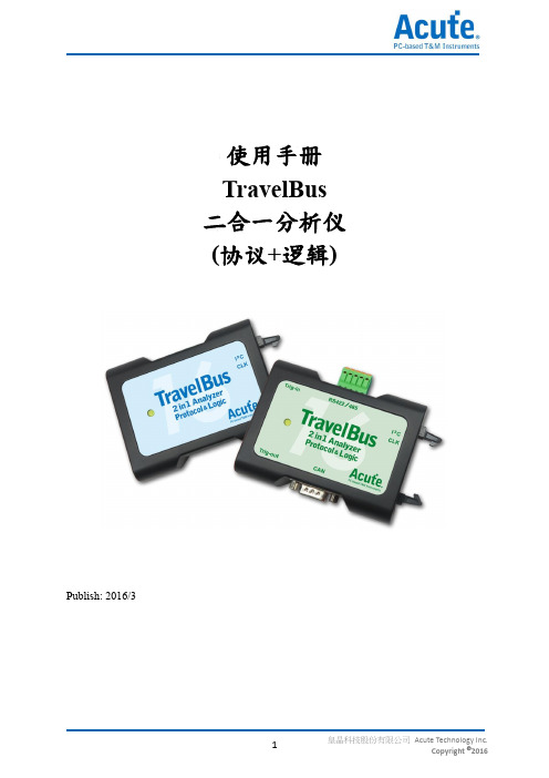
使用手册TravelBus二合一分析仪(协议+逻辑)Publish: 2016/3目录第一章安装与设置 (3)硬件安装 (3)软件安装 (3)第二章功能列表与操作 (4)协议分析 (4)逻辑分析 (12)第三章型号说明 (21)第四章技术支持 (22)第一章安装与设置硬件安装将TravelBus以标配的USB3.0连接线接上电脑的USB port,待确定连接完成后就可以开启软件使用,并且将信号线接到待测物上以便观察。
软件安装请至/sc/p4_download.php?did=1选TravelBus下载。
安装结束后,桌面上与程序集中都有TBA的启动图标,可以任选一个来启动TBA( )。
启动软件后,会出现主菜单画面,可以选择进入逻辑分析或协议分析。
开启档案能够开启存储的档案(.TBW)第二章功能列表与操作协议分析视窗画面1.工具列:包含选择通讯协议、采集、搜寻和输出等功能,其中输出的格式有.csv和.txt2.报告视窗:将译码数据以封包格式列表3.波形:如果勾选波形选项,则会在此显现信号波形和译码结果4.状态列:和TravelBus连机状况、目前的通讯协议以及所采集时间/预计采集时间等资讯5.细节/统计/过滤视窗:显示报告视窗的细节和统计结果,也能使用过滤来筛选资讯6.波形光标计算:波形区中有光标可以拖曳到想要的位置,计算出两个光标间的时间差通讯协议选择画面( )1.选择不同的通讯协议2.通道:可以选择LA接口或是I2C接口。
LA接口是排线上以数字0到15所标示的16个通道,供一般信号使用;I2C接口相关设置于下页说明。
3.波形:TravelBus自动侦测和显示信号的波形和最高频率。
4.选项:可以设置通讯协议的封包格式。
5.触发电平:可依据信号的电平来设置不同的触发值。
如果选择I2C接口,则是排线上以SCL和SDA标示的两条线,其作用是使用内部专用IC,内含施密特触发器可以用来量测跳变较为缓慢的I2C信号。
GW2ANR系列FPGA产品数据手册DS961-1.3说明书
GW2ANR系列FPGA产品数据手册DS961-1.3, 2023-02-27版权所有© 2023广东高云半导体科技股份有限公司、Gowin、晨熙、高云均为广东高云半导体科技股份有限公司注册商标, 本手册中提到的其他任何商标,其所有权利属其拥有者所有。
未经本公司书面许可,任何单位和个人都不得擅自摘抄、复制、翻译本文档内容的部分或全部,并不得以任何形式传播。
免责声明本文档并未授予任何知识产权的许可,并未以明示或暗示,或以禁止发言或其它方式授予任何知识产权许可。
除高云半导体在其产品的销售条款和条件中声明的责任之外,高云半导体概不承担任何法律或非法律责任。
高云半导体对高云半导体产品的销售和/或使用不作任何明示或暗示的担保,包括对产品的特定用途适用性、适销性或对任何专利权、版权或其它知识产权的侵权责任等,均不作担保。
高云半导体对文档中包含的文字、图片及其它内容的准确性和完整性不承担任何法律或非法律责任,高云半导体保留修改文档中任何内容的权利,恕不另行通知。
高云半导体不承诺对这些文档进行适时的更新。
目录目录 (i)图目录 (iv)表目录 (vi)1 关于本手册 (1)1.1 手册内容 (1)1.2 相关文档 (1)1.3 术语、缩略语 (2)1.4 技术支持与反馈 (3)2 产品概述 (4)2.1 特性概述 (4)2.2 产品信息列表 (6)3 结构介绍 (7)3.1 结构框图 (7)3.2 Memory (8)3.2.1 SDR SDRAM (8)3.2.2 NOR FLASH (9)3.3 可配置功能单元 (10)3.4 输入输出模块 (11)3.4.1 简介 (11)3.4.2 I/O电平标准 (12)3.4.3 I/O逻辑 (14)3.4.4 I/O逻辑工作模式 (16)3.5 块状静态随机存储器模块 (22)3.5.1 简介 (22)3.5.2 存储器配置模式 (23)3.5.3 存储器混合数据宽度配置 (24)3.5.4 校验位功能配置 (25)3.5.5 同步操作 (25)3.5.7 BSRAM操作模式 (25)3.5.8 时钟模式 (27)3.6 数字信号处理模块 (28)3.6.1 简介 (28)3.6.2 数据A、数据B和进位C的加法/减法运算DSP操作模式配置 (31)3.7 时钟 (32)3.7.1 简介 (32)3.7.2 全局时钟网络 (32)3.7.3 锁相环 (35)3.7.4 高速时钟 (37)3.7.5 DDR存储器接口时钟管理DQS (37)3.8 长线 (38)3.9 全局复置位 (38)3.10 编程配置 (38)3.11 片内晶振 (39)4 电气特性 (40)4.1 工作条件 (40)4.1.1 绝对最大范围 (40)4.1.2 推荐工作范围 (41)4.1.3 电源上升斜率 (41)4.1.4 热插拔特性 (42)4.1.5 POR特性 (42)4.2 ESD性能 (42)4.3 DC电气特性 (42)4.3.1 推荐工作范围DC电气特性 (42)4.3.2 静态电流 (44)4.3.3 I/O推荐工作条件 (44)4.3.4 单端I/O DC电气特性 (45)4.3.5 差分I/O DC电气特性 (46)4.4 AC开关特性 (47)4.4.1 CFU开关特性 (47)4.4.2 BSRAM开关特性 (47)4.4.3 DSP开关特性 (47)4.4.4 Gearbox开关特性 (47)4.4.5 时钟和I/O开关特性 (47)4.4.7 锁相环开关特性 (48)4.5 编程接口时序标准 (48)5 器件订货信息 (49)5.1 器件命名 (49)5.2 器件封装标识示例 (50)图目录图3-1结构概念示意图 (7)图3-2 CFU结构示意图 (10)图3-3 IOB结构示意图 (11)图3-4 GW2ANR系列FPGA产品I/O Bank分布示意图 (12)图3-5 I/O逻辑输出示意图 (14)图3-6 I/O逻辑输入示意图 (14)图3-7 IODELAY示意图 (15)图3-8 GW2ANR的I/O寄存器示意图 (15)图3-9 GW2ANR的IEM示意图 (16)图3-10普通模式下的I/O逻辑结构示意图 (16)图3-11 SDR模式下的I/O逻辑结构示意图 (17)图3-12 I/O逻辑的DDR输入示意图 (17)图3-13 I/O逻辑的DDR输出示意图 (17)图3-14 I/O逻辑的IDES4输入示意图 (18)图3-15 I/O逻辑的OSER4输出示意图 (18)图3-16 I/O逻辑的IVideo输入示意图 (18)图3-17 I/O逻辑的OVideo输出示意图 (19)图3-18 I/O逻辑的IDES8输入示意图 (19)图3-19 I/O逻辑的OSER8输出示意图 (19)图3-20 I/O逻辑的IDES10输入示意图 (19)图3-21 I/O逻辑的OSER10输出示意图 (20)图3-22 IO逻辑的IDDR_MEM输入示意图 (20)图3-23 IO逻辑的ODDR_MEM输出示意图 (20)图3-24 IO逻辑的IDES4_MEM输入示意图 (21)图3-25 IO逻辑的OSER4_MEM输出示意图 (21)图3-26 IO逻辑的IDES8_MEM输入示意图 (21)图3-27 IO逻辑的OSER8_MEM输出示意图 (22)图3-28单端口、伪双端口及双端口模式下的流水线模式 (26)图3-29独立时钟模式 (27)图3-30读写时钟模式 (27)图3-31单端口时钟模式 (28)图3-32 DSP宏单元 (29)图3-33 GW2ANR时钟资源 (32)图3-34 GCLK象限分布示意图 (33)图3-35 DQCE结构示意图 (34)图3-36 DCS接口示意图 (34)图3-37 DCS Rising Edge模式下的时序示意图 (34)图3-38 DCS Falling Edge模式下的时序示意图 (35)图3-39 PLL示意图 (35)图3-40 GW2ANR HCLK示意图 (37)图3-41 DQS示意图 (38)图5-1器件命名方法–ES (49)图5-2器件命名方法–Production (49)图5-3器件封装标识示例 (50)表目录表1-1术语、缩略语 (2)表2-1产品信息列表 (6)表2-2 GW2ANR-18列表 (6)表3-1 GW2ANR系列FPGA产品支持的输出I/O类型及部分可选配置 (13)表3-2 端口介绍 (14)表3-3 BSRAM信号功能 (23)表3-4存储器配置列表 (23)表3-5双端口混合读写数据宽度配置列表 (24)表3-6伪双端口混合读写数据宽度配置列表 (25)表3-7时钟模式配置列表 (27)表3-8 DSP端口描述 (29)表3-9内部寄存器描述 (30)表3-10 PLL端口定义 (36)表3-11片内晶振的输出频率选项 (39)表4-1绝对最大范围 (40)表4-2推荐工作范围 (41)表4-3电源上升斜率 (41)表4-4热插拔特性 (42)表4-5 POR电压标准 (42)表4-6 GW2ANR ESD - HBM (42)表4-7 GW2ANR ESD - CDM (42)表4-8推荐工作范围内DC电气特性 (42)表4-9静态电流 (44)表4-10 I/O推荐工作条件 (44)表4-11单端I/O DC电气特性 (45)表4-12差分I/O DC电气特性 (46)表4-13 CFU时序参数 (47)表4-14 BSRAM时序参数 (47)表4-15 DSP时序参数 (47)表4-16 Gearbox时序参数 (47)表4-17外部开关特性 (47)表4-18片内晶振特性参数 (48)表4-19 PLL特性参数 (48)1关于本手册 1.1手册内容1关于本手册1.1手册内容GW2ANR系列FPGA产品数据手册主要包括高云半导体GW2ANR系列FPGA产品特性概述、产品资源信息、内部结构介绍、电气特性、编程接口时序以及器件订货信息,帮助用户快速了解高云半导体GW2ANR系列FPGA产品以及特性,有助于器件选型及使用。
MULTI GLOSS 268 商品说明书

MULTI GLOSS 268UNI GLOSS 60A wide array of display modes(corresponding to six languages)You can measure by selecting Basic mode,Continuous,Statistics from the Mode screen.You can select the measurement angle from the Geometry selection screen and display two angles or three angles at the same time.(MULTI GLOSS 268)You can select Mode,Geometry selection,Difference,and Calibrationfrom the Main Menu screen.Geometric selection selected two angles.(MULTI GLOSS 268)Geometric selection selected three angles.(MULTI GLOSS 268)PASS/FAILStandard value nameSample nameLarge screen size and easily viewable liquid crystal display.Easy operation with mode scroll wheel.By operating the mode scroll wheel in accordance with easy-to-understand menu items,you can set a wide array of functions easily.Wide measurement range that can be measured from plastic to metal surface with a high gloss finish :0.0~2,000GU(in the case of 20˚)The gloss difference measurement of thestandard/sample and the PASS/FAIL evaluation.You can make a pass/fail evaluation by setting the limit value.You can enter the sample name and the standard value name in the measurement result.Autodiagnosis function of calibrationThis means a little frequency of calibration and long-term stability.In addition,if the calibration is required,the message will be displayed.Calibrating standardProtective holder•It has data compatibility with the previous MULTI GLOSS 268/UNI GLOSS 60,and improves repeatability and reproducibility.•Approx.10,000measure-ments are available with one AA (R6)size alkaline battery.(20˚,60˚,85˚)(60˚)1981∗ Microsoft Excel ®97or higher.Windows ®,Windows NT ®and Excel ®is a trademark or registered trademark of Microsoft Corporation of America or its subsidiaries.AEFDPK Printed in Japan9242-4890-11 2003KONICA MINOLTA SENSING,INC.4OS Windows ®98/2000/Me/XP,Windows NT ®4.03-91,Daisennishimachi,Sakai.Osaka 590-8551,JapanKonica Minolta Photo Imaging U.S.A.,Inc.725Darlington Avenue,Mahwah,NJ 07430,U.S.A.Phone:888-473-2656(in USA),201-529-6060(outside USA)FAX:201-529-6070Konica Minolta Photo Imaging Canada,Inc.1329Meyerside Drive,Mississauga,Ontario L5T 1C9,Canada Phone:905-670-7722FAX:905-795-8234Konica Minolta Photo Imaging Europe GmbH Europaallee 17,30855Langenhagen,Germany Phone:0511-740440FAX:0511-741050Konica Minolta Photo Imaging France S.A.S.Paris Nord II ,385,rue de la Belle-Etoile,B.P.50077,F-95948Roissy C.D.G.Cedex,France Phone:01-49386550/01-30866161FAX:01-48638069/01-30866280Konica Minolta Photo Imaging UK Ltd.Precedent Drive,Rooksley Park,Milton Keynes United Kingdom Phone:01-908200400FAX:01-908618662Konica Minolta Photo Imaging Austria GmbH Amalienstrasse 59-61,1131Vienna,Austria Phone:01-87882-430FAX:01-87882-431Konica Minolta Photo Imaging Benelux B.V.Postbus 6000,3600HA Maarssen,The Netherlands Phone:030-2470860FAX:030-2470861Konica Minolta Photo Imaging (Schweiz)AG Riedstrasse 6,8953Dietikon,Switzerland Phone:01-7403727FAX:01-7422350Konica Minolta Business Solutions Italia S.p.A.Via Stephenson 37,20157,Milano,Italy Phone:02-39011-1FAX:02-39011-219Konica Minolta Photo Imaging Svenska AB Solnastrandvägen 3,P.O.Box 9058S-17109,Solna,Sweden Phone:08-627-7650FAX:08-627-7685Konica Minolta Photo Imaging (HK)Ltd.Room 1818,Sun Hung Kai Centre,30Harbour Road,Wanchai,Hong Kong Phone:852-********FAX:852-********Shanghai OfficeRm 1211,Ruijin Building No.205Maoming Road (S)Shanghai 20020,China Phone:************FAX:************Konica Minolta Photo Imaging Asia HQ Pte Ltd.10,Teban Gardens Crescent,Singapore 608923Phone:+656563-5533FAX:+656560-9721KONICA MINOLTA SENSING,INC.Seoul Office801,Chung-Jin Bldg.,475-22,BangBae-Dong,Seocho-ku,Seoul,Korea Phone:02-523-9726FAX:02-523-9729DimensionsUnits :mmWith dedicated Data transfer software(gloss-link),the data management such as data transfer to Excel ®∗is easy.。
KLA 2835 Broadband Plasma逻辑器件专用明场检测仪说明书
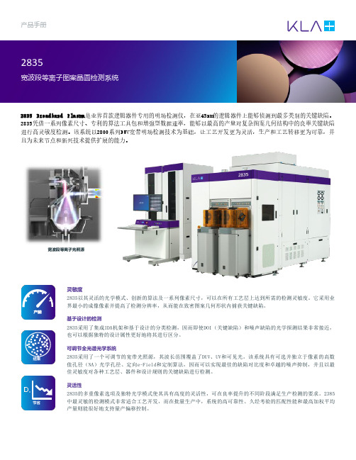
产品手册2835 Broadband Plasma 是业界首款逻辑器件专用的明场检测仪,在亚45nm 的逻辑器件上能够侦测到最多类别的关键缺陷。
2835凭借一系列像素尺寸、专利的算法工具包和增强型数据速率,能够以最高的产量对复杂图案几何结构中的良率关键缺陷进行高灵敏度检测。
该系统以2800系列DUV 宽带明场检测技术为基础,让工艺开发更为灵活,生产和工艺转移更为可靠,并且为未来节点和新兴技术提供扩展的能力。
宽波段等离子光照源灵敏度2835以其灵活的光学模式、创新的算法及一系列像素尺寸,可以在所有工艺层上达到所需的检测灵敏度。
它采用业界最小的成像像素并提高了检测分辨率,从而能在致密图案几何形状内捕获关键缺陷。
基于设计的检测2835采用了集成IDA 机架和基于设计的分类检测,因而即使DOI (关键缺陷)和噪声缺陷的光学探测结果非常接近,也可以根据独特的设计属性更好地将其进行区分。
可调节全光谱光学系统2835采用了一个可调节的宽带光照源,其波长范围覆盖了DUV 、UV 和可见光。
该系统具有可选并独立于像素的高数值孔径(NA )光学孔径、定向e-Field 和定制算法,因而可以实现最佳的缺陷对比度和卓越的噪声抑制,并且以最佳灵敏度对各种工艺层、器件和设计规则的关键缺陷进行检测。
灵活性2835的多重像素选项及独特光学模式使其具有高度的灵活性,可在良率提升的不同阶段满足生产检测的要求。
2385中最灵敏的检测模式非常适合工艺开发,而在批量生产中,系统的高可靠性、久经考验的匹配性能和最高加权平均产量则能很好地支持量产偏移控制。
结果节省成效时间创新算法和宽波段光照减少了工艺变化和前层缺陷所引起的错误缺陷计数。
这种先进的噪声抑制功能与Inline Defect Organizer™ (iDO™)相结合,可加速完成可实际操作的直方图,并将资源集中在最关键的良率问题上。
通用性与连接性2835与KLA 的暗场和电子束检测仪,以及电子束检视设备采用相同的通用平台与用户界面。
la系列逻辑分析仪

频率/Hz
800M 400M 200M 100M
0
LA5034
LA1016 LA1024 LA1032
2K
32K
LA2232 LA2432 LA1232 LA1432 128K
LAP1046 LAP1045
LAP1025 LA2532
LA2832 LA2932
LAP1532
LA1732 LA1832
分析 SD/MMC
CF
ModBus
代码 分析
88005511
LA/LAP系列逻辑分析仪采用了先进的大规模集成电路,整合了USB2.0、 CPLD、FPGA、嵌入式系统等技术,集 逻辑分析仪、总线分析仪、协议分析仪、频率计、逻辑笔等多种仪器之大成于一身,具有高性能低价格、携带方便、 简单易用、扩展性好等优点,是代替传统设备的最佳选择。可用于各种数字电路的开发、测量、分析和调试工作,是 电子研发、电子测量工程师、高校师生的科研开发和教学的得力助手。为适应不同设备的分析,LA/LAP系列具有多种 不同的频率、容量等配置的产品以供选择(具体型号差别见下页表格)。
10 2. 我 一 定 要 为 更 长 的 测 量 时 间 而 付 出 巨 大 资 金 购 买 容
量更大的逻辑分析仪吗?(特有的Timing-State模式) 答 案 是 否 定 的 。 如 图2所 示 致 远 电 子 推 出 的L A / L A P系 列
逻 辑 分 析 仪 特 有 的Timing-State模 式 能 够 使 您 在 不 增 加 对 设备的投入的同时拥有更长的测量时间。同样一个只有 32K容量的逻辑分析仪使用100M采样频率测量一个10K的波 形 , 使 用T i m i n g - S t a t e模 式 可 以 使 测 量 时 间 延 长 到8 0 m s。 具 有 Timing-State模 式 的 逻 辑 分 析 仪 比 没 有 TimingState模式的逻辑分析的记录时间足足延长了250倍。
3B S CIENTIFIC 精密光学仪表说明书
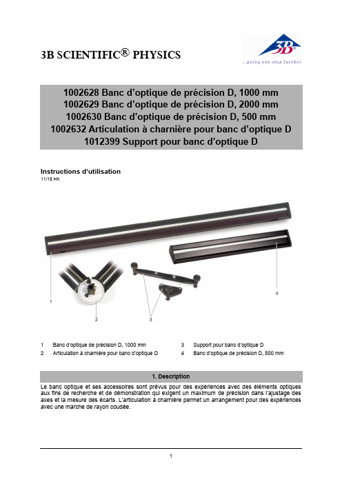
3B SCIENTIFIC ® PHYSICSInstructions d‘utilisation11/15 Hh1 Banc d’optique de précision D, 1000 mm2Articulation à charnière pour banc d’optique D3 Support pour banc d’optique D4Banc d’optique de précision D, 500 mmLe banc optique et ses accessoires sont prévus pour des expériences avec des éléments optiques aux fins de recherche et de démonstration qui exigent un maximum de précision dans l’ajustage des axes et la mesure des écarts. L’articulation à charnière permet un arrangement pour des expériences avec une marche de rayon coudée.2.1 Bancs optiquesLe banc optique est constitué d’un profilé tri-angulaire en aluminium anodisé noir, protégé contre tout basculement, résistant à la flexion et à la torsion, avec antiglissement. Des deux côtés se trouvent une graduation continue en cm/mm. Les surfaces d’appui présentent deux rainures permettant le logement optionnel de deux pieds ou d’un pied et d’un appui. A l’avant se trouvent trois perforations pour la fixation des plaques frontales ou de l’articulation à charnière.Illustration 1 Profilé triangulaire2.2 Jeu de pieds pour banc optiqueCe jeu compr end deux pieds de rail et d’un appui en aluminium anodisé noir. Il permet d’ajuster la hauteur du banc optique dans un appui à quatre ou trois points..Longueur des pieds: 270 mm Illustration 2 Pied de railIllustration 3 Appui2.3 Articulation à charnièreL’articulation est fabriquée en aluminium ano-disé noir et peut être orientée des deux côtés à 90°. Une graduation angulaire permet de rég-ler l’angle. L’axe pivotant comprend une co-lonne qui loge les éléments optiques.Angle de rotation: ± 90° Graduation angulaire: ±180°Pas: 1°Hauteur de colonne: 60 mm Etendue pour manches: 10 mm à 14 mmIllustration 4 Articulation à charnière3.1 Montage des pieds du rail∙Introduire les vis à tête carrée dans la rainure de guidage sous le rail profilé et les fixer en les serrant.∙Régler la hauteur avec la vis d’ajustage.∙Fixer la position avec la vis de blocage. 3.2 Montage de l’articulation à charnière∙Retirer la plaque frontale en desserrant les troisvis de fixation.∙Placer l’articulation à charnière sur le rail et la fixer avec les trois vis.∙Relier le second rail à l’articulation.3.3 Coulisseaux et aides de montagerecommandésPour le montage d’éléments dans l’axe op-tique:∙Cavaliers:Pour pivoter des éléments dans l’axe optique: ∙Cavalier pivotant D (1012467) Pour déplacer des éléments à la verticale de l’axe optique:∙Cavalier à déplacement latéral D (1002644)Pour positionner des éléments à côté de l’axe optique:∙Bras de rallonge D (1002646)。
- 1、下载文档前请自行甄别文档内容的完整性,平台不提供额外的编辑、内容补充、找答案等附加服务。
- 2、"仅部分预览"的文档,不可在线预览部分如存在完整性等问题,可反馈申请退款(可完整预览的文档不适用该条件!)。
- 3、如文档侵犯您的权益,请联系客服反馈,我们会尽快为您处理(人工客服工作时间:9:00-18:30)。
支持多种通信协议 与不同工作模式 即时协议数据搜寻
切换至逻辑分析模式 并叠加示波器
即时协议 数据统计
逻辑分析仪模式: 采集数字波形信号,搭配多样触发条件做信号定位,辅以总线解码。 可叠加示波器同时比对数字与模拟信号,适用于信号品质分析。
流程图式触发条件功能:
使用流程图示设定协议触发条件, 辅以 Counter/Timer 功能以提升 流程控制能力
2017.12
TravelLogic
二合一分析仪 (协议+逻辑)
• PC-based
• USB3.0 接口/电源
• 34 通道 (最多)
• 2GHz 时序 (最高) / 200MHz 状态分析
• 8Gb 总內存 (最大)
• 电压侦测 : 2 组, 便于得知电压变化 • 可与皇晶或其他品牌 DSO 叠加成 MSO
123 x 76 x 21 mm³
• 总线触发 I : I²C, SPI, UART, USB PD3.0
• 总线触发 II : BiSS-C, CAN2.0, DALI, I²S, I3C, LIN2.2, LPC, MDIO, Modbus, PWM, SVID, ...
• 总线触发 III : eMMC 4.5, eSPI, MIPI SPMI 2.0, NAND Flash, SD 3.0, Serial Flash (SPI NAND)
8 / 125Mb
8 / 1Gb
16 / 1Mb
16 / 62Mb
16 / 500Mb
16 / 1Mb
32 / 31Mb
32 / 250Mb
8 / 2Mb,
8 / 125Mb,
4 / 2Gb, 8 / 1Gb,
16 / 1Mb
16 / 62Mb, 32 / 31Mb
16 / 500Mb, 32 / 250Mb
+5V ~ -5V
50mV
±100mV + 5%*Vth
±30V DC, 12Vpp AC
0.25Vpp @50MHz, 0.5Vpp @150MHz, 0.8Vpp @250MHz
200KΩ//<7pF
20KΩ//<3pF
5℃~45℃ (41℉~113℉) / -10℃~65℃ (14℉~149℉)
输入埠 (叠加用) 触发脉冲 输出埠 (叠加用) 参考时钟输入 参考时钟输出 连接器种类 I
II
III 波形放大缩小 使用语系 波形高度 全域窗口/报告窗口 快速鼠标定位 导入通道名称 快速新增总线分析 触发光标/辅助光标 数据记录器
总线解码
主机尺寸 排线 测试夹
解码器
编码器 长x宽x高 (mm³) (Data / CLK / Analog / GND)
即时通信协议分析报告
即时隐藏数据 方便查看
每个阶层都有详细的参数 可供调整触发条件
快速检视功能 右键拖曳波形区,快速检视波形频率与跳变数
当前设定一目了然
单次或快速重复采集
快速叠加示波器设定
产品内容:
停止采集后可观察波形对应协议解码
协议分析仪模式 (Protocol Analyzer) 即时显示解码数据,无需等待分析,直观易懂。 适用于大量但有间隔之协议数据。
Biphase Mark, Differential-Manchester, Manchester (Thomas, IEEE802.3), Miller,
Modified Miller, NRZI, …
AMI(Standard, B8ZS, HDB3), Biphase Mark, CMI, Differential-Manchester,
SD3.0 (SDIO), Serial Flash, Serial IRQ, SGPIO, Smart Card, SMBus, SMI, S/PDIF, SPI, SPI-NAND, SSI, ST7669, SWD,
SWP, SVI2, SVID, UART, UNI/O, USB 1.1, USB PD 3.0, Wiegand, ...
200MHz
触发
分辨率 通道数 状态 事件 前置 / 后置 忽略次数 种类 总线 I
总线 II
触发电平 输入电平 输入阻抗 温度 相位误差 输入/出埠
协议分析/ 数据记录/ 数据监控模式
软件功能
总线 III
群组 范围 分辨率 触发电平精度 非破坏最大耐压 灵敏度 数据通道 模拟通道 工作温度/存放温度
系统需求 • USB 3.0 port • Win 7, Win 8, Win 10 (64 位) • PC RAM 16GB (推荐) or 8GB (至少)
USB 3.0
协议分析仪模式: 硬件解码,不带波形,可以即时显示通信协议数据,也可以长时间记录保存协议数据资料, 亦可叠加示波器查看真实波形。适用时机:通信协议除错初期分析。
Lissajous, LPC, LPT, M-Bus, Math, MDIO, MHL CBUS, Microwire, MII (GMII, RGMII), MIPI DSI, MIPI RFFE,
MIPI SPMI 2.0, Modbus, NAND Flash, NEC IR, PECI, PMBus, Profibus, PS/2, PWM, QI, RC-5, RC-6, RGB Interface,
---
LIN2.2, MDIO, Modbus, PMBus, Profibus, PWM,
SMBus, SVID, USB1.1, USB PD3.0
---
eSPI
有 (可使用鼠标滚轮)
English / 繁体中文 / 简体中文
可改变
有
有
有
有
1/25
可存储于硬盘中
1-Wire, 3-Wire, 7-Segment, A/D Mux Flash, AccMeter, ADC, APML, BiSS-C, BSD, CAN 2.0, Close Caption, DALI,
• 协议分析仪模式:硬件解码, 实时显示协议数据, 可长仪总线解码 : BiSS-C, CAN, eMMC5.0, eSPI, I²C, I²S, I3C, NAND Flash, Profibus,
SD3.0, SPI, SVID, UART, USB1.1, USB PD3.0... 80余种, 见背面
Profibus, SMBus, SVI2, SVID, USB1.1
eMMC4.5, eSPI,
MIPI SPMI 2,
---
NAND Flash, SD3.0,
Serial Flash (SPI NAND)
2 (ch0~7, ch8~15 & clk0)
4 (ch0~7, ch8~15 & clk0, ch16~23, ch24~31 & clk1)
DMX512, DP Aux, EDID, eMMC 5.1/MMC, eSPI, FlexRay, HDMI CEC, HD Audio, HDLC, HDQ, HID over I²C, I²C,
I²C EEPROM, I²S, I3C, I80, IDE, ITU656, IrDA, JTAG, LCD1602, LED_Ctrl, LIN2.2, Line Encoding, Line Decoding,
TL3000E/B 系列
技术指标
电源
电源
待机功耗
最大瞬时功耗
传输界面
时序分析 (异步,采样频率)
状态分析 (同步,外部时钟)
资料存储方式
通道 (Data / Clock / Analog / Ground)
总内存
时序分析
时序 vs. 通道数 vs. 内存
2GHz 1GHz 500MHz 250MHz
1ns
500ps
16
32
16
16
Yes
Yes (0~1048575 times)
字节, 通道, 宽度, 超时, 单一/多条件, 外触发
I²C
I²C, SPI, UART, USB PD3.0
BiSS-C, CAN2.0, DALI, HID over I²C, I²S, I3C,
---
LIN2.2, LPC, MDIO, Modbus, PMBus,
型号 TL3017E TL3134E TL3134B TL3234B+
软件画面
通道数 17 34 34 34
采样率 1GHz 1GHz 1GHz 2GHz
存储容量 16Mb 1Gb 1Gb 8Gb
总线触发 I²C I I, II
I, II, III
协议分析仪模式 I²C I I, II
I, II, III
< 1ns
TTL 3.3V (上升沿 / 下降沿)
> 8 ns
TTL 3.3V, Pulse Width
10MHz, Vpp=3.3 to 5V
10MHz, TTL 3.3V
MCX jack / female
I²C
I²C, SPI, UART, USB PD3.0
BiSS-C, CAN2.0, DALI, HID over I²C, I²S, I3C,
Manchester (Thomas, IEEE802.4), MLT-3, Miller, Modified Miller, NRZI, Pseudoternary, …
123 x 76 x 21 (mm³)
绝缘线 40 条 (32 / 2 / 2 / 4)
20
40
© 2017 All right reserved. Acute Technology Inc. Acute and Acute logo is a registered trademark of Acute Technology Inc.