GeneralTouch触摸屏使用说明书
触摸屏选择指南说明书
HOME ABOUT PRODUCTS SUPPORT SALESTouch Screen Selection GuideGeneralA touch screen is an assembly that is mounted in front of a video display. It is activated by touching, with a stylus or finger, the selected area on the display that indicates the desired function. The touch screen or frame has an independent X-Y coordinate system that is calibrated to the display matrix. The X-Y coordinates of the position of the stylus are communicated to the host computer causing the desired action.Other than voice recognition, touch input is probably the most natural human interface to any computing device. It is particularlyuseful and popular in those applications where the user is relatively unskilled in the operation of a computer. For that group ofusers, keyboards tend to be intimidating devices.Touch screens have been used for many years, mainly in applications such as point of sale, public information kiosks, industrialand process control, military displays, medical displays and interactive video systems.Touch Screens for the Factory FloorAs computer based graphic displays and workstations replace switch and indicator banks as the primary man-machine interface for machine and process control, touch screens are becoming increasingly popular as the input device of choice There are several reasons for this increased popularity.q Using touch screens, pop-up alpha and numeric keypads replace fixed, expensive industrial keyboards.q Since video switch banks are software programmable, making changes is significantly less costly than modifying a control panel that contains mechanical switches and indicators.q Using touch input an unskilled user can operate a complex computing device by interacting directly with the video display with relative ease.q Touch targets can be any shape size or color which makes screen design more flexible.q Touch input can provide instant audio and/or visual feedback to tile user to confirm his choice.q Touch active menus can help guide tile user through complex sequences of commands or actions.q Complicated control panels can be simplified by only displaying valid options for any control sequence.This guide is intended to provide a designer with basic tools and selection criteria to allow the most appropriate touch technology and controller configuration to be chosen for their industrial control application.Present Touch Technologiesq Ideally a touch screen would have the following characteristics:q It would not overlay the display and would, therefore, not degrade the display image.q It would have resolution equivalent to that of the video display.q It would be activated by 1) any size stylus 2) conducting or non-conducting styli or 3) a gloved or non-gloved finger.q It would provide a positive, tactile feedback to the operator.q It would be modular and capable of being added to a display and computer in the same manner that other input devices are added.q It would be impervious to dust, grease, moisture chemical or oil vapors or pressure hose down that may be present in a hostile environment.Unfortunately, none of the touch screens currently manufactured have all of those characteristics. Accordingly, the selection of any touch technology is a compromise that will depend on the particular application and environment.There are four major touch technologies--analog resistive, capacitive, scanning infrared (IR) and surface acoustic wave (SAW). All of these technologies provide an assembly consisting of a touch screen overlay or touch frame and a separate controller. The controller is a printed circuit board assembly that must be mounted in either the display device or the computer.Analog ResistiveAnalog resistive screens consist of a sandwich of Mylar and plastic or glass. Usually the Mylar overlay is hard coated to resist abrasion. The two layers are separated from each other by transparent elastic spacer dots. The inside surfaces of the sandwich are coated with a uniform transparent thin film conductive coating, usually indium-tin-oxide (ITO). In operation, a voltage is alternately applied along the horizontal and vertical axes. When the Mylar overlay is depressed and its conductive layer makes contact with the energized layer, that voltage is sensed and transmitted to a controller containing an analog-to-digital converter. The voltage is converted to a digital X or Y touch location. Although the basic analog resistive technology has infinite resolution, the actual system resolution is limited to the resolution of the A-D converter and is generally greater than 1,000x1,000 points.CapacitiveA cross section of a capacitive screen is shown. A glass panel is coated with a conductive coating(usually ITO) that is fused into the glass. The coating is connected to four electrodes at the edges of thescreen. Each electrode is connected to an oscillator circuit. When an operator touches the screen, thebody capacitance of the operator causes a change in the impedance of the screen. The impedancechange causes the oscillator frequencies to vary, and the frequency differentials are converted into X-Ycoordinates by an A-D converter. As with the analog resistive screen, the basic capacitive screen hasinfinite resolution but the system resolution is limited by the signal-to-noise ratio which puts a practicalupper limit on the A-D converter resolution--typically 1,000x 1,000 points.Scanning Infrared (IR)The IR technology is the onlytechnology that does not overlay thedisplay with an additional screen orscreen sandwich. An array of infrared (IR) light emitting diode (LED)/photodetector pairs are mounted in a plastic frame. Using the IR spectrum allowsambient light to be filtered out and makes possible the use of opaque (to thevisible spectrum) plastic frames to hide the photo devices. Thus, the arrayframe simply looks like a bezel. In operation, the LED/photo detector array iscontinuously and sequentially scanned horizontally and then vertically Whenan operator touches the display breaking one or more of the light beams, the X-Y position of the touch stylus is transmitted to the host computer. Themaximum resolution using an interpolation technique is approximately doublethe number of LED/photo detector pairs in the array. Using interpolation, whenan odd number of beams is broken along either axis, the X or Y coordinate ofthe center beam is transmitted, but when an even number of beams is broken,the coordinates of the interpolated beam are calculated and transmitted to thehost computer.Surface Acoustic Wave (SAW)The surface acoustic wave technology is the latest of the touch input technologies and uses inaudible acoustic waves traveling over the surface ofa glass panel at precise speeds in straight lines. X and Y transmittingtransducers are located along the horizontal and vertical edges of a glass plate.Corresponding X and Y receiving transducers are located at the opposite edgesof the glass plate. A reflective array made of powdered glass is printed along theedges of the glass plate. The array consists of .2 mil thick by 1/2 inch widediagonal, parallel lines. In operation, the transducer generates a surfaceacoustic wave which travels along the axis of the reflector array. At eachreflector element, a small amount of the energy in the wave is deflectedorthogonally to the direction of the wave, travels over the surface of the glassand is again deflected orthogonally toward the receiving transducer by a mirrorimage reflector. Since the energy in the wave is reduced as it travels the lengthof the reflective array, the reflector elements are placed increasingly closertogether to compensate for the decreasing energy level. When an operatortouches the screen, a portion of the energy is absorbed by the touch stylus. Thisreduced energy level is detected and, by comparing the speed of the receivedsignal with the known speed of the SAW on glass, an X or Y coordinate locationis registered. As with capacitive screens, the basic SAW technology has infiniteresolution but is limited by the signal-to-noise ratio which puts a practical limit onthe A-D converter--typically 900x900 coordinate locations.Touch Screen ControllersMost manufacturers offer two controller configurations--ISA Bus and Serial-RS232.q ISA bus controllers are contained on a standard printed circuit plug-in board and can only be used on ISA or EISA PCs. Depending on the manufacturer they may be interrupt driven, polled or be configured as another serial port.q Serial controllers are contained on a small printed circuit board and are usually mounted in the video monitor cabinet. They are then cabled to a standard RS232 serial port on the host computer.SoftwareMost touch screen manufacturers offer some level of software support which include mouse emulators, software drivers, screen generators and development tools for Windows, OS/2, Macintosh and DOS.Most of the supervisory control and data acquisition (SCADA) software packages now available contain support for one or more touch technologies.Selection ProcessGenerally there four factors that must must considered for any touch screen application:q The basic touch technologyq The touch controller configurationq The screen surface treatment (not applicable to IR touch screens)q Compatibility with the applications softwareTouch Technology Evaluation Factorsq Resolution-- The smallest detectable increment of stylus movement establishes the touch resolution. Low resolution may be adequate to activate large targets but for mouse tracking or small target activation, resolution equivalent to that of the monitor is desirable.q Parallax-- If a significant variance exists between the target position on the CRT and the point on the touch screen matrix that, when activated by a stylus, causes a touch to be registered the operator could select a different target area than the desired target.q Environment-- The buildup of a layer of dust, oil, grease or any foreign substance on fingers, harsh chemical vapors and hose-down by pressure hoses may cause improper touch operation.q Stylus-- Types of styli typically used with touch screens are bare finger and gloved finger. Occasionally other types of styli including pencil erasers, tips of a pen, may be pointed at the screen and the user expects a responseq Transmissivity-- Overlay touch screens act as a neutral density filter and, therefore attenuate the light from the CRT.q Abrasion-- Touch screen abrasion is experienced in one of three ways. 1) Cleaning of screen with an abrasive 2) Impacting the screen witha sharp object 3) Gradual wearing of the screen from repeated useTouch Technology Selection CriteriaAnalog ResistiveAdvantagesq Highest resolution (better than 1 K x 1 K), smooth mouse tracking and small target activationq Will operate with virtually any stylus including gloved/ungloved fingersq Low parallax with spherical screen that conforms to CRT faceplateq Impervious to dust, oils, grease, moistureq Touch has some tactile feedbackDisadvantagesq Although Mylar overlay has a hard coat and is somewhat abrasion resistant, it can be damaged by gouging from a sharp instrument q Hose down can cause unwanted activation of target areasq Lowest transmissivity of all touch technologies - 55%-65%CapacitiveAdvantagesq High resolution - 1 K x 1 K, smooth mouse tracking and small target activationq Low parallax with spherical screen that conforms to CRT faceplateq Impervious to dust, oils, grease, moistureq Hose-down does not cause unwanted activation of targetsq Impervious to scratching by all but the hardest materialsq High transmissivity - >85%Disadvantagesq Will not respond to gloved finger or any non-conductive stylusScanning Infrared (IR)Advantagesq Best image quality as there is no overlayq Impervious to scratchingq Activates with gloved or ungloved finger and any stylus that is large enough to break IR light beam (typically >.25") Disadvantagesq Low resolutionq Exhibits worst parallax problem of all technologies for CRT use since light beams do not follow curvature of CRT faceplate q May cause unintended activation of target prior to finger contact with CRT caused by IR light beam location above surface of CRT q Pressure hose down may cause unwanted target selectionq Dust, oil or grease buildup on frame that impedes light beam may cause malfunctionSurface Acoustic Wave (SAW)Advantagesq High transmissivity - >92%q High resolution - 900 x 900, smooth mouse tracking and small target activationq Low parallax with spherical screen that conforms to CRT faceplateq Impervious to scratching by all but the hardest materialsq Only technology with Z axis controlDisadvantagesq Pressure hose down may cause unwanted target selectionq Dust, oil or grease on surface of touch screen may cause malfunction or unwanted target selectionTouch Controller Selection CriteriaBus Controllerq Bus controllers are available for ISA/EISA and Micro channel. For any other bus, a serial controller must be usedq Bus controllers usually take a half-length slotq Bus controllers can only be driven a few feet. Therefore the distance between the video monitor and computer must be relatively short q Certain designs are interrupt driven and require the assignment of an IRQ line. Others have a serial port format and require the assignment of a COM port.q Bus controllers are mechanically easier to install.Serial ControllersSerial Controllers are necessary if:q A computer bus other than ISA/EISA or Micro channel is usedq A computer slot is not available but a serial port is availableq There is a separation between the computer and monitor of several feet or moreq No IRQ line is availableSurface Treatment Selection CriteriaTwo types of surface treatment are offered for most overlay screens - clear and anti-glareq Anti-glare screens use an etched surface to diffuse reflected light thus scattering specular reflected light and reducing glare. Unfortunately, this also causes some diffusion of the image. The diffusion is limited if the screen is close to the display surface, but some diffusionremains.q Clear screens have no diffusion of the display image but the screen is highly reflectiveThe choice of clear or anti-glare may be somewhat affected by the intensity and direction of ambient light in the viewing area, but in the final analysis, it is usually a subjective decisionSoftware CompatibilityAfter the touch screen technology and controller have been selected:q It is necessary to determine that the software drivers supplied with the touch screen are compatible with tile latest version of the user's operating systemq If standard application software is being considered. it is necessary to determine that the software is compatible with the drivers and touch hardwareq If software is being developed, it is necessary to ascertain that adequate software drivers and development tools are available SummaryWe have shown that there are many factors to consider in the proper selection of a touch screen, primarily focused on the application and the environment in which it will be used. We have attempted to provide the designer with adequate information to make an informed choice of a touch screen technology that best suits the application.Nortech offers a complete line of touch input workstations, control stations and video monitors. Analog resistive and capacitive touch screens are offered as standard products, since one or the other will best satisfy most industrial control applications for use with CRTs. For generally clean environments, surface acoustic wave (SAW) touch screens may be substituted, if desirable. Nortech does not support scanning infrared (IR) touch screens for use with CRTs.Copyright 1996-2006, Nortech Engineering, Inc., All Rights Reserved。
LG Banter Touch手机说明书
3” TOUCH SCREEN The QVGA display is one of the largest in itsclass for better message and picture viewingand easier navigation.QWERTY KEYBOARD At five lines deep, it has room for a separatenumbers line plus an emoticon key. It’s morespacious too so thumbs don’t get cramped.2MP CAMERA AND CAMCORDER It takes pix that are easy to share when you’re out and about and rich to look at back on the computer screen. It takes video clips as well.BLUETOOTH® CONNECTIVITY Chat away on an earpiece or listen to tunes on a stereo headset — all untethered. Even print photos and contact info wirelessly.ADVANTAGESLG Electronics MobileComm10101 Old Grove Rd., San Diego, CA 92131Customer Service: (800) All materials in this datasheet including, without limitation, the design, the text, and any marks are the property of LG Electronics, Inc. Copyright ©2010 LG Electronics, Inc. ALL RIGHTS RESERVED. LG is a registered trademark of LG Electronics, Inc. All product and service marks contained herein that are not LG Electronics, Inc. proprietary marks are the trademarks of their respective owners. LG Electronics, Inc. makes no claim to such properties. Phone features and specifications are subject to change without prior notice. The use of non-LG approved accessories will void the warranty and may result in damage to the phone or other dangerous conditions. Please consult product manual for full details. microSD is a trademark of SanDisk. The Bluetooth word mark and logos are registered trademarks owned by Bluetooth SIG, Inc. and any use of such marks by LG Electronics MobileComm, U.S.A., Inc. is under license.r Stereo Sound via Handset or Bluetooth ® Wireless Technologyr Create & Manage Playlistsr Music Library – organized by artist, album, genre, and playlistsr Multitask While Playing Music – minimize player to send messages, edit contacts, or browse the webr Video Player – supports WMV, MP4, 3GP, and 3G2 formatsr microSD™ Memory Slot for Extra Storage** P hone supports up to a 16GB memory card (sold separately).CAMERA/VIDEOr2 Megapixel Camera and Camcorderr Camera Resolutions: 1600 x 1200 (default),1280 x 960, 640 x 480, 320 x 240 Pixelsr Image Editor: zoom, crop, draw on,add stamps, flip, rotate, mirror,add fun frames, apply filter, andadjust brightness, contrast, or colorr Slide Show – view images stored on phone or memory card r Multishot – take up to 7 shots in rapid succession*r Video Resolutions: 320 x 240 and 176 x 144 (default) Pixels r Video Length (approximate): up to 15 seconds (for sending) or up to 60 minutes (for saving)**r Camera and Video Zoom: up to 10 levels*r Customizable White Balance,*** File Quality,*** Color Effects,*** Brightness,*** Fun Frames, Self-Timer, Shutter Sounds, and Night Mode r Mute – record videos with or without sound r Print Images to a Bluetooth® Printer*Varies by image resolution. Camera settings of 1600 x 1200 and 1280 x 960 do not support multishot function. Default camera settingof 1600 x 1200 pixels does not support zoom function.**Depends on unused memory.***Available in both video and camera modes.MOBILE MEDIA r Mobile Web†r BREW® Capable †r Text, Picture, Video, and Voice Messaging †r easy edge SM – download games, ringtones, pictures, and more †dial-up networking, object push, basic printing, advanced audio distribution (stereo), audio/video remote control, file transfer, human interface device (keyboard only), and phone book access r Save up to 20 Bluetooth Pairingsr Bluetooth Stereo Headset Support for Listening to Music*r Send Contacts, Calendar Events, Images, and Videos via Bluetooth Wireless Technologyr Print User-Generated Images via Wireless Technology* A ccessories sold separately.VOICE/AUDIOr One-Touch Speakerphoner Speaker-Independent Voice Commands r Voice-Activated Dialing r Text to Speech r Voice Memos (up to 1 minute or no limit)*r MP3 music ringer support (clips from hitsongs)**†r 32 Unique Ringtones + Vibrate & Silent Modesr Set Voice Memos as Ringtones r TTY/TDD Supportr Hearing Aid Compatible (M4/T4 rating)*Depends on available memory.**Not assignable from microSD card.TOOLS & DATA r USB Mass Storage – transfer files between microSD card and PC*r Internal Memory Size: 85MB (for savingfiles to phone)r Tools: Calendar, Alarm Clock, Calculator, EZ Tip Calculator, Notepad, World Clock, Date Finder, Unit Converter, Stopwatch, and Drawing Panel r Phone Book with 1,000 Contacts – each stores 7 numbers, 2 email addresses,1 birthday, 1 memo, 1 URL, and 1 picture ID***Requires USB cable (included) and microSD card (sold separately).**Dependent on media and other data stored on the phone.†U.S. Cellular service required. Product features subject to change. Features based on carrier program availability.T O U C H。
触摸屏操作手册

触摸屏操作手册一、简介触摸屏是一种常见的人机交互设备,通过触摸屏可以直接通过手指或者特定的工具来进行操作和控制。
本操作手册旨在向用户介绍触摸屏的使用方法和注意事项,以便更好地实现各种功能。
二、基本操作1. 点击:在触摸屏上轻触一下,表示点击操作。
点击可以选择菜单、打开应用程序或者进行其他各种操作。
2. 滑动:用手指在触摸屏上滑动,可以进行滚动、拖动或者翻页的操作。
滑动可以实现页面切换、查看长文本内容等功能。
3. 放大缩小:用两个手指并拢或张开,在触摸屏上进行放大或缩小的操作。
放大缩小可以用于查看图片、网页或者进行地图缩放等。
三、多点触控触摸屏支持多点触控,利用多个手指可以实现更多的操作功能。
1. 双指缩放:用两个手指并拢或张开进行放大或缩小的操作,与基本操作中的放大缩小类似。
2. 旋转:用两个手指在触摸屏上进行旋转的操作,可以调整图片、地图等的旋转角度。
3. 拖拽:用两个手指并拖动可以移动物体或者改变物体的位置。
拖拽可以用于拖动文件、调整窗口大小等操作。
4. 其他:根据触摸屏设备的不同,还可以支持更多的多点触控操作,比如双击、按住移动等。
四、手势操作触摸屏还支持各种手势操作,通过特定的手指动作可以触发不同的功能。
1. 上滑/下滑:用手指从屏幕底部向上或向下滑动,可以打开或关闭通知栏、展开或收起菜单等。
2. 左滑/右滑:用手指从屏幕左边向右或向左滑动,可以进行页面切换、查看上一张照片等操作。
3. 双击:用手指快速点击屏幕两次,可以进行快速放大或缩小、双击打开应用程序等操作。
4. 长按:用手指在屏幕上长时间按住不动,可以弹出操作菜单、选择文本等功能。
五、注意事项1. 确保手指干净和屏幕无油污,这可以增加触摸屏的灵敏度和精确度。
2. 避免用力按压触摸屏,轻触即可触发操作。
3. 不要使用尖锐物体或者过于粗糙的物体来触摸屏,以免刮伤或损坏屏幕。
4. 避免长时间不动触摸屏,以免屏幕长时间亮着造成能源消耗过多。
新中控盒,触摸屏的连接说明
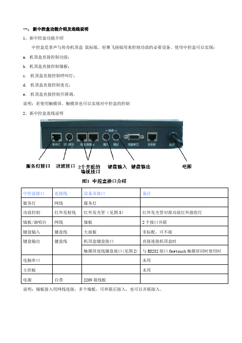
一、新中控盒功能介绍及连线说明
1、新中控盒功能介绍
中控盒是掌声与传奇机顶盒鼠标版、轻舞飞扬版用来控制功放的必要设备。
使用中控盒可以实现:
a. 机顶盒直接控制功放;
b. 机顶盒直接控制墙板;
c.机顶盒直接控制呼叫灯;
d.机顶盒直接控制麦克;
e.机顶盒直接控制升降调。
说明:若使用触摸屏,触摸屏也可以实现对中控盒的控制
2、新中控盒连线说明
说明:墙板接入用网线连接,多个墙板,可串联后接入,也可以并联接入。
3、适用范围
适用于传奇机顶盒、掌声v1.0机顶盒、掌声v2.1机顶盒,目前不支持pc点歌。
二、触摸屏分类及连线说明
说明:若为RS232接口的触摸屏接掌声机顶盒,安装在显示器上时未内置“电平转换器”(图7),需要将“电平转换器”连接在电阻屏的RS232接口,再连接其他设备。
3、用到的连线及设备说明
a.RS232接口的触摸屏自带的连线(图4)
触摸屏键盘接口2
触摸屏RS23接口触摸屏键盘接口1
b. RS232转USB线(掌声机顶盒2.0以上使用)(图5)
c. RS232转串口线(传奇机顶盒使用)(图6)
d.电平转换器(RS232接口的触摸屏接掌声机顶盒时使用)(图7)
e.红外屏鼠标接口线(图8)
4、常见问题分析。
Touch中文操作手册2篇

Touch中文操作手册2篇Touch中文操作手册(第一篇)一、为什么要学习Touch中文操作?Touch中文操作是一种先进的技术,它能够通过触摸屏幕来进行文字输入和操作。
随着智能手机、平板电脑等移动设备的普及,Touch中文操作已经成为许多人日常生活和工作中必备的技能。
学习Touch中文操作可以提高我们的工作效率,使我们能够更快速地进行文字输入和操作,节省时间和精力。
二、Touch中文操作的基本技巧1. 触摸屏幕:Touch中文操作的核心就是通过触摸屏幕来进行操作。
我们可以轻触屏幕上的文字、按钮或图标来选择或点击它们。
要注意轻触的力度要适中,过轻或过重都会影响操作效果。
2. 滑动手势:滑动手势是Touch中文操作中常用的操作方式之一。
我们可以用手指在屏幕上滑动来浏览、切换页面或进行其他操作。
要注意滑动的方向和速度,以获得想要的操作效果。
3. 捏合手势:捏合手势是Touch中文操作中常见的放大和缩小操作方式。
我们可以用两个手指在屏幕上捏合或展开来实现放大或缩小操作。
要注意手指的位置和力度,以获得合适的放大或缩小比例。
4. 多点触控:Touch中文操作支持多点触控,即可以用多个手指同时操作屏幕。
我们可以用多个手指同时触摸屏幕,进行各种复杂的操作,提高操作效率和灵活性。
5. 输入法切换:在Touch中文操作中,我们常常需要切换输入法来输入不同的文字。
我们可以通过屏幕上的输入法切换按钮或手势来切换输入法,以便输入不同的文字和符号。
三、Touch中文操作的高级技巧1. 编辑文本:在Touch中文操作中,我们经常需要编辑文本,如修改文字、复制粘贴等。
我们可以用手指在屏幕上选中文字,然后通过屏幕上的编辑菜单来执行各种编辑操作。
2. 快速操作:为了提高工作效率,Touch中文操作中有一些快速操作的技巧。
比如,在列表中快速滑动可以快速滚动到列表的顶部或底部;双击屏幕可以实现一些特殊操作等。
3. 手势操作:Touch中文操作中还支持一些手势操作,如双指上划可以显示通知中心,双击Home键可以打开最近使用的应用等。
触摸屏的使用流程

触摸屏的使用流程1. 概述触摸屏是一种用于输入和操作设备的显示屏,它能够感知触摸动作并将其转化为相应的操作。
本文将介绍触摸屏的使用流程,以帮助用户正确地操作触摸屏设备。
2. 开机与关机1.开机:按下设备的电源按钮,等待设备启动。
启动完成后,触摸屏将显示设备的主界面。
2.关机:在设备主界面上找到并点击设置图标,然后选择关机选项,按照系统提示进行关机操作。
3. 主界面导航触摸屏的主界面通常会显示多个应用图标或功能模块,用户可以通过触摸屏上的手指滑动来浏览不同的界面。
以下是主界面导航的基本操作方法: - 滑动:在触摸屏上用手指从左向右或从右向左滑动,切换到上一个或下一个界面。
- 点击:轻触触摸屏上的应用图标或功能模块,打开相应的应用或进入相应的功能。
4. 应用操作触摸屏上的应用通常具有不同的功能,用户可以根据需要打开并进行相应的操作。
以下是应用操作的基本方法: - 打开应用:在触摸屏主界面上找到相应的应用图标,轻触图标打开应用。
- 返回主界面:在应用界面上从底部向上滑动,或者点击手机下方的返回键,返回触摸屏主界面。
- 切换应用:在应用界面上从屏幕左侧向右滑动,或者双击触摸屏主界面的多任务按钮,切换到上一个应用。
- 关闭应用:在应用界面上从屏幕顶部向下滑动,或者点击应用界面的关闭按钮,关闭当前应用。
5. 文字输入触摸屏通常提供虚拟键盘用于文字输入,用户可以通过触摸屏上的键盘进行文字输入。
以下是文字输入的基本方法: - 点击输入框:在需要输入文字的应用界面上,点击输入框以获得焦点。
- 点击键盘:在触摸屏上点击相应的键盘按钮,输入对应的文字。
- 切换键盘:在键盘界面上点击键盘上方的语言切换按钮,选择相应的语言键盘。
- 删除文字:在键盘界面上点击删除按钮,逐个删除输入框中的文字。
6. 手势操作触摸屏支持多种手势操作,以提供更便捷的控制方式。
以下是常用的手势操作方法: - 捏合手势:使用两个手指同时从触摸屏上向内或向外移动,以放大或缩小屏幕上的内容。
资料模板:触摸屏使用手册(新)

目录220V 12V 手柄麦克主用接口备用接口音箱触摸屏VGA 接口触摸屏232接口USB 接口电源开关2. 呼叫调度台正常运行后,会显示如下界面:图2 调度台运行界面示意图左上角圆球状态代表调度台的接口状态:绿色代表主用通信正常,黄色代表备用通信正常,红色代表通信故障。
●用户键区本系统用户键区为分页设计,目前为13页;每页设计为72个用户键。
●用户呼叫记录状态区在这里可以显示用户的呼入呼出状态和号码,记录呼叫的进程和通话记录。
●功能键区在这里有系统设定的功能键:主辅应答键、重拨、转接、保持、切换。
按需要点击系统设置可自行添加会议、自动、簿等功能键。
2.1单个用户的呼叫当进行单个用户的呼叫时,直接点按相应的用户键就可以了,若用户呼叫的对象没有预设在用户键上,可以通过拨号键来完成呼出,拨号键的具体用法将在功能键介绍中进行说明。
2.2多个用户的呼叫当调度员需要进行多个用户的呼叫时,只需依次按下相应用户的用户键即可;当车站值班员需要进行多个用户呼叫时,需要先按下会议键,然后点按需要呼叫的用户键,或者当正在通话的用户使用的是麦克时,此时点按麦克键,该按钮会显示为手柄,然后可拿起手柄进行第二个用户的呼叫。
当有用户呼入时,相应的用户键会闪烁并伴有振铃音,如下图:图3 调度台呼入状态示意图此时,有3种接听方法●点按相应的用户键来接听●点按主应答键接听●点按辅应答或者直接拿起手柄接听当有用户正在通话,同时又有其他用户呼入时,调度员操作台会直接把该用户接通并在用户键上显示,而车站值班员操作台会响铃提示值班员,值班员可以选择通过手柄直接接听或者挂掉当前通话再接听。
4.功能键介绍用户在平时使用中只需按相应的用户键呼叫或在来电时按应答键接听即可,其他常用功能键有:拨号键、紧急键、切换键、麦克键、会议键、转接键、保持键、备用键等。
本键用来呼叫没有预先定义到用户键按钮上的用户,需要使用时可先按下“拨号”键,然后在弹出的拨号盘上按相应的号码后按呼出即可。
触摸屏中文说明书(只供参考-可编辑)
触摸屏中⽂说明书(只供参考-可编辑)前⾔为了您能尽快轻松⾃如地操作本机,在您开始使⽤本机之前,请仔细阅读我们随机提供的说明书,以便您能正确使⽤本机。
本⼿册中的信息资料如有变更,恕不另⾏通知,且不承担此⼿册产⽣的错误或者疏漏引起的任何事件。
⼀、主要功能·2.8⼨全触摸屏,320X240点阵全彩⾼速TFT显⽰屏全屏触摸·⽀持MP3、WMA、WA V⾳乐格式·⽀持MPEG-4(AVI)视频格式·⽀持JPEG格式图⽚浏览·内置麦克风,超长时间录⾳·节能设置,亮度可⾃由调节,⾃动关机·多种⾳效、循环可供选择·⽀持多国⽂字·USB2.0⾼速传输·⽀持电⼦书阅读·⽀持游戏功能,·移动硬盘功能·⽀持固件升级⽀持SD扩展,可⽀持到2GB SD卡⼆、外型及按键说明:1、本说明书中要求短按的时候您要在播放器上停留1S-2S,2、长按锁键可锁定机器的触摸屏,以防⽌误动作。
如需要解锁,请再长按锁键。
3、本机触摸屏可⽤⼿触摸,也可以⽤本机后壳上触摸笔孔中所带触摸笔进⾏操作。
三、主界⾯在主界⾯中,短按⼀下该菜单确认该功能,长按进⼊四、⾳乐播放在主菜单选择“⾳乐播放”选项,再长按进⼊⾳乐播放模式,进⼊以下界⾯:键选择上下曲,按调节⾳量。
2.按进⼊放⾳设置菜单。
其中设置⽅法和系统设置菜单中的⼀样,后来详述。
其中⾳效设置可设置成以下⼏种设置:,可选择正常(NOR)/3D/摇滚(ROCK)/流⾏(POP)/古典(CLASS)/重低⾳(BASS)/爵⼠(JAZZ)/⽤户⾃定(USER)8种⾳效模式。
3.按进⾏A-B复读短按⼀下,在播放状态下设置复读起始点,显⽰状态“A-”;再次短按,设置复读结束点,显⽰状态“A-B”,开始循环复读;短按“,,退出复读模式;在暂停状态下“A-B复读”功能⽆效。
当在“A-”、或“A-B”状态下,长按“”键进⾏快进或快退将取消“A-B复读”功能。
触摸屏操作说明书
目录0.前言 (2)1.操作注意事项 (2)2.操作台触摸屏画面构成及说明 (3)2-1画面阶层及上下触摸屏画面分配 (3)2-2各画面说明 (3)各画面共同部分 (3)①运转监控画面 (8)①-1掘削条件未成立明细显示Window (12)①-2油脂充填运转设定Window (13)②计测监控画面 (14)③泵启动画面 (17)④推进油缸选择画面 (18)④-1同步设定Window (20)⑤辅助操作画面 (21)⑤-1盾尾油脂操作画面 (22)⑤-1-1自动注入周期设定Window (25)⑤-2超挖刀操作画面 (26)⑤-3铰接操作画面 (28)⑥其他设定画面 (31)⑥-1系统设定Window (32)⑥-2其他设定Window (33)⑥-3土压控制参数设定画面 (34)⑥-4PLC内部AD/DA监控画面 (35)⑥-5异常履历表示画面 (36)⑦异常数据表示画面 (37)⑦-1故障诊断提示Window (38)⑧系统出错表示画面 (39)3.推进油缸操作箱画面构成 (40)3-1画面阶层 (40)3-2各画面的说明 (41)各画面的共同部分 (41)①泵启动画面 (42)②推进油缸操作画面 (43)③其他设定画面 (46)③-1系统设定Window (47)④系统出错表示画面 (48)4.异常内容一览 (49)4-1触摸屏自我诊断异常情况及处理一览 (50)4-2系统出错内容及对应一览 (51)4-3运转关系异常及对应一览 (52)4-4掘削条件未成立导引内容及对应一览 (56)0.前言本说明书为φ6250mm泥土压式盾构操作台及推进油缸操作箱専用的操作説明書(別冊)。
因内容非独立成立,阅读时请参照主机说明书一起使用。
本说明书中的画面为説明用,与实际显示画面可能会有不同,敬请注意。
1.操作注意事項用触摸屏操作时,请仔细阅读以下事项,安全使用。
(1)勿用手指以外的东西操作触摸屏。
硬物操作会损坏触摸屏表面的菜单开关和液晶屏。
触摸屏功能说明 文档
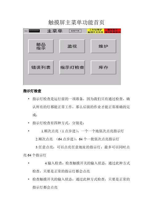
触摸屏主菜单功能首页指示灯检查•指示灯检查是运行前的一项准备,因为我们只有通过检查,确认所有的灯都能正常工作,那么后面的作业才能正常准确的完成;•指示灯检查有四种方式,分别是:• 1.顺次点亮(1点步进):一个一个地依次点亮指示灯2.顺次点亮(64点步进):64个一批依次点亮指示灯3.任意点亮:可以点亮任意地址的指示灯;最多可以同时点亮64个指示灯• 4.输入检查:检查触摸开关的输入状态,通过此种方式检查,只要是正常的指示灯都会点亮•检查触摸开关的输入状态,通过此种方式检查,只要是正常的指示灯都会点亮在指示灯检查时也可以同时检查三色灯和蜂鸣器是否正常部品作业指示画面•通过此画面,我们可以知道当前作业的序列号以及车种等相关信息。
而由该画面上面提示可知道当前系统中的一些情况,比如通信连接,是否有错误发生,是否有触摸开关失效。
•而该画面左上角01窗号处即是隐藏按钮。
该按钮功能即是强制完成功能,即无论当前作业进度如何,长按此按钮3秒或以上就会强制请求到下一条数据•在当前指示画面首页中我们可以简单的看到当前体统运行过程中的一些相关信息。
而当前指示画面有十页,根据需要,可以前进或后退查看当相关详细的具体信息。
•在所有的当前指示信息中,都只是介绍当前作业序列号的有关信息。
比如车种型号,车种颜色,内饰颜色,规格等等监视功能说明在监视功能状况下,可以了解整个IPMS系统当前运行状况,即当前缓存情况,当前料架信息,控制站信息和各功能块当前状态情况错误列表功能•当IPMS在运行过程中发生了故障的时候,就会弹出表示故障概况的故障显示对话框,同时在部品指示窗口中的故障区域里也会有“故障发生”指示,这时候应该针对该故障采取相应的措施;•如果想要了解有关故障履历或者曾经发生过的故障的详细信息,请参看故障履历窗口中的有关内容;•如果想要了解当前发生的报警信息,请参看当前发生报警窗口中的有关信息•当报警消除以后,列表中的故障信息会自动消失;并且会在窗口中的解除时间一栏中显示出该故障的解除时间;•必要的时候解除报警信息•当想要忽略所发生故障的有关内容时,可以解除该故障;当选定待解除的故障并点选故障解除按钮以后,该故障即被解除并且在解除时间一栏中显示出该故障的解除时间,若点故障解除按钮故障仍不能解除,则需联系IPMS系统管理员•触摸屏维护功能说明维护模式的切换•当我们要切换到维护模式时,这时需点住隐藏按钮(隐藏按钮即为下图勾画出的两个区域,且两个按钮要同时按住)的同时点执行按钮则进入维护模式。
触摸屏控制器用户手册说明书
Touchpad controllerUser Manual – installation – operationContentsGeneral drawings2 Fixing control panel to wall21. General installation instructions32. Connecting modular cables33. Connecting additional control components43.1 Introduction43.2 Control function ‘switch on/off’43.3 Control function ‘change fan speed’44. Initialising system (prepare for use)55. Operation55.1 Functions of keys55.2 Operation56. Troubleshooting6Fixing control panel to wall 1234General drawings1. General installation instructions— Read this page carefully before starting the installation.— All installation work must be carried out by expert personnel.— Ensure that the appliances are disconnected from the mains before they are opened.— Avoid unnecessary contact with electronic components.Introduction:1. This manual is intended for all Biddle appliances with a built-in electronic interface.2. This manual describes the installation and use of the Biddle electronic control system.3. Several functions in this manual are only available from a certain version of a control system component. These functions are marked. Whenever you change an existing system you should compare the version number on the component with the version number in the manual.Installation details:1. Up to 10 appliances may be connected to one control panel.2. The total length of all modular cables in one system must be less than 100 metres.3. When installing the modular cable care should be taken to avoid interference with the cable by (electro)-magnetic fields as far as possible (therefore do not lay the cable close to high-voltage cables, fluorescent light starters, etc.)Components:The control system comprises the following components:1. Control panel consisting of 3, 4, 5 or 6 keys.2. Built-in interface with 3 or 6 output contacts, depending on the type of appliance.3. Modular cable including modular plugs, for connecting the control panel to one or more appliances. N.B.: B.T. type telecommunication cables are not suitable! The cable can be ordered from Biddle and is available in various lengths.Installation procedure:1. Connect modular cables + install control panel.2. Connect any customised controls, with control components with potential-free contacts.3. Provide all appliances with a power supply.4. Initialise the system.2. Connecting modular cablesA. Appliances with external connectionsType of appliance:— Modular fan coil unit (PS-B)— Air curtain (KW/MW/GW/KE/ME/GE/CAT/CAT-V)— Cassette air heater (KLV/KLV-E/KLVV)B.Appliances with internal connections Type of appliance:— Fan coil unit (B)— Extractor fan cabinetN.B.: The modular cables (X70) can be connected to both connectors (XiS)(see fold-out sheet, page 2).3. Connecting additional control componentsIf you have no control components to install, you can skip this section and go on to section 4 ‘Initialise the system’.3.1 IntroductionAs well as the basic system functions, there is also a possibility of connecting control components (e.g. room thermostat, timer BMS-controlled relay or door switch) to an appliance. Combinations of control components can also be used.N.B.: For remote switching on blocks X62/X72 volt free contacts are required. These contacts are advised to be gold plated and to have a low relay less than 20 m W to handle 1 mA at 5Vdc.Possible control functions:Control function Control range Adaptation to interface ofconnected appliance Connection points onblock X62/X72Connectionsummaryswitch on/off one appliance (local)none terminals T and G see § 3.2 switch on/off all appliances in system (general)remove jumper 6terminals T and G see § 3.2 change fan speed one appliance (local)none terminals D, P and G see § 3.3 change fan speed all appliances in system (general)remove jumper 5terminals D, P and G see § 3.3 N.B.: The function ‘switch on/off’ does not apply to the KLVV-unit. Consult the user manual of the unit when you want to connect control components to terminals T and G.3.2 Control function ‘switch on/off’1. Remove T-G bridge (X62/X72. see fold-out sheet, page 2) only from the appliance towhich the control component is to be connected.2. Connect the control component between T and G.— Contact made between T and G: Applicance stand-by.— No contact between T and G: Appliance/system off.3. General switching If the control function is to apply to the whole system, remove jumper 6(X64). This should only be done in the appliance to which the control component isconnected. Place the jumper on the reserve positions intended for it (X65), so that it can beused again later.3.3 Control function ‘change fan speed’1. Connect the control component between D and/or P and G (X62/X72, see fold-out sheet, page2). Important: do not disconnect T-G bridge.— Contact made between D and G : Appliance/system runs 1 speed higher than the controlpanel indicates (both speed and electric heating).— No contact between D and G Appliance/system working as indicated on the control panel.— Contact made between P and G Appliance/system runs at fan speed three (electric heatingstage remains unchanged, either one or two).— No contact between P and G Appliance/system working as indicated on the control panel.— Contact made between D, P and G: Appliance/system runs at fan speed three and electricheating stage two.N.B.: The functions using terminals P and G only are available from interface version V4.0Rev.06. Code IC 10 in the illustration on page 2 shows where you can find the version number.2. General switching: If the control function is to apply to the whole system, remove jumper 5(X64) as indicated in the facing illustration. This should only be applied to the appliance towhich the control component is connected. Place the jumper on the reserve positions intendedfor it (X65), so that it can be used again later.NB: General switching’ of the contact between P and G requires control pad version V2. IRev.02 or higher and interface version V4.O Rev.07 or higher. You can find the versionnumber on the printed circuit board of the control pad. In an existing system the control padcould be of a previous version. If the contact between P and G should still apply to the wholesystem, you should order a new control pad from Biddle.3. If the electric heating is not to be stepped up at the same time, remove jumper 4 (X64) asindicated in the illustration. This should be done in each appliance for which the function is required. Place the jumper on the reserve positions intended for it (X65), so that it can be used again later.14564. Initialising the system (prepare for use)When to use:1. On first installation.2. On each extension of the system.3. When checking cables.To start the procedure:1. Press keys 1, 2 and 3 simultaneously.—After 10 seconds the LEDs on keys 1 and 2 will start to flash. This flashing will continue for two minutes.— The LED on key 3 will then flash the same number of times as there are appliances in the system. The system is now ready for use.5. Operation5.1 Functions of keysLED lights when speed setting is ‘low’.LED flashes during initialisation.— Set speed to ‘low’.— Switch off appliance.— Start initialisation.LED lights when speed setting is ‘medium’LED flashes during initialisation.— Set speed to ‘medium’.— Switch off appliance.— Start initialisation.LED lights when speed setting is ‘high’.LED indicates number of appliances connected when initialisation is complete.— Set speed to ‘high’.— Switch off appliance.— Start initialisation.LED lights when electric heating is set to ‘low’.— Set electric heating to ‘low’.— Switch off electric heating.— Set electric heating to ‘low’ and speed to ‘low’.LED lights when electric heating is set to ‘high’.— Set electric heating to ‘high’.— Switch off electric heating— Set electric heating to ‘high’ and speed to ‘medium’.LED-R lights when setting is ‘Recirculate’ or standby.LED-V lights when setting is ‘Ventilate’.— Set air intake valve to ‘Ventilate’.— Set air intake valve to ‘Recirculate’.5.2 OperationA.Turn on appliance : Press key 1, 2, 3, 4 or 5.B.Turn off appliance : Press speed key (1, 2 or 3) on which the LED is illuminated. LED-R (if present) remains illuminated.Safety functions electric heating:1.The following scenarios will automatically be corrected:— Speed off, electric heating on.— Speed low, electric heating high.2. Appliance operates differently from control panel:If the appliance has just been switched off, it may start running again spontaneously.This is in order to discharge the heat stored in the heating elements.6.TroubleshootingAppliance not working:Check point Possible cause Action1no voltage on appliance check power supply to appliance2system not yet initialised start initialisation; see section 4 ‘Initialising the system’3poor contact in modular plug;check contacts (ensure plastic packaging is completely removed)4no bridge between terminals T and G fit bridge between terminals T and G on block X62/72. (see section 3‘Connecting Customised Control components’)5fuse(s) in appliance defective replace fuse (only to be done by skilled personnel)Appliance not working as expected:Check point Fault Possible cause Action/explanation1appliance (with electric heating)starts working spontaneously continued running of electricallyheated appliancesBiddle safety function; see section 5‘Operation’control components are notproperly connectedcheck system; see section 3‘Connecting Customised ControlComponents’2appliance works differently fromexpectationthe jumpers(l-3 red) on the interface are no longer in accordance with factory setting check jumper position against Specifications for factory setting jumper block X643electric heating not working appliance has overheated check maximum thermostat(see appliance manual) Factory setting jumper block X64Appliance type Jumper 1Jumper 2Jumper 3Jumper 4-6 appliance with electric heating with 2 positions present open present present CAT-air curtain open present present present KLV-E open present open present KLVV open open open presentall other appliances present present present present。
触摸屏操作说明书
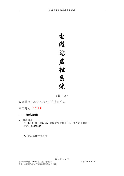
电灌站监控系统(共7页)设计单位:XXXX软件开发有限公司竣工时间:2012.9一.操作说明1.初始画面当PLC柜通上电以后,触摸屏先去按下F5,进入如下画面:密码:888888882、进入选择控制界面第第3、手自动切换当最上面选择到1至9号管道手动时,只能用左边红色框圈标注:1至3号管道手动,4至6号管道手动,7至9号管道手动。
第当最上面选择到1至9号管道自动时,只能用左边红色框圈标注:1至3号管道自动,4至6号管道自动,7至9号管道自动。
4、操作示范(示范启动1号管道自动)a、准备条件:1、看提升泵的就地面板上按钮有打到远程控制状态,提升泵远控灯亮起。
2、看蝶阀就地面板上有没打到远程控制状态,蝶阀远控灯亮起。
蝶阀全关灯亮起。
b、开启操作:先打开1#真空泵启动按钮,真空泵打开,过段时间节点灯亮起,表明一号真空泵压力达到300。
当提升泵的节点灯亮起。
表明压力已经达到所需状态,可以点击启动按钮。
然后提升泵的运行灯会亮起来,过8s蝶阀的开始开阀,全关灯灭掉,过30s后,蝶阀的全开灯亮起,表明启动正常。
当正常启动后,水正常抽上去之后,要停机,请按停止按钮。
然后蝶阀马上关闭蝶阀,蝶阀全开灯灭掉,全关灯过30秒后亮起。
提升泵过20秒后停机。
当正常启动后,水没有正常抽上去之后,需按急停按钮,马上停机。
蝶阀马上关闭,提升泵马上停机。
c、2-9号操作2-9号操作与1号一致。
注:这些操作都必须是在柜子上面的切换开关打到触摸屏控制,才可以实现通过触摸屏来实现控制。
第。
触摸屏操作方法和技巧

触摸屏操作方法和技巧
触摸屏操作方法和技巧可以帮助用户更加高效地使用设备。
以下是一些通用的触摸屏操作方法和技巧:
1. 单击:轻触屏幕一次,类似于鼠标的左键单击,用于选择应用程序、打开文件、确认选择等。
2. 双击:快速连续地点击屏幕两次,用于打开应用程序、放大或缩小页面等。
3. 长按:长时间按住屏幕上的一个位置,通常会出现菜单选项或其他操作选择。
4. 滑动:在屏幕上使用手指移动,用于滚动页面、查看更多内容等。
5. 捏放缩放:使用两个手指捏合或张开,可以放大或缩小页面、图片等。
6. 滑动解锁:在锁屏状态下,向右滑动屏幕解锁。
7. 边缘手势:一些设备支持从屏幕边缘滑动,例如从屏幕底部向上滑动可以打开多任务视图。
8. 多点触控:触摸屏可以同时支持多个手指触摸,使用多点触控可以实现更多操作,如旋转屏幕、快速切换应用等。
9. 拖拽:触摸屏上按住一个对象,然后移动手指,可以将对象拖动到想要的位置。
10. 双指右键:在某些设备上,使用两个手指同时点击屏幕可以模拟鼠标右键点击。
这些方法和技巧仅为常用操作,具体操作方法可能因设备和应用程序而有所不同。
用户可以根据自己的需求和设备的使用说明来探索更多的操作方法。
触摸屏使用说明

触摸屏使用说明触摸屏使用说明1、介绍1.1 触摸屏的概述在本章节中,将详细介绍什么是触摸屏,它的基本原理以及在各种设备中的应用。
1.2 触摸屏的种类在本章节中,将常见的触摸屏种类,如电阻式触摸屏、电容式触摸屏、表面声波触摸屏等,并介绍它们的特点和适用场景。
2、触摸屏的安装2.1 触摸屏的准备工作在本章节中,将介绍触摸屏安装前的准备工作,包括检查硬件设备、连接线缆等。
2.2 触摸屏的安装步骤在本章节中,将详细描述触摸屏的安装步骤,包括固定触摸屏、连接数据线和供电线等。
3、触摸屏的操作3.1 基本操作在本章节中,将介绍触摸屏的基本操作方式,如单击、滑动、双指缩放等,并提供相应的操作指南和注意事项。
3.2 高级操作在本章节中,将介绍触摸屏的高级操作方式,如多点触控、手势识别等,并提供相应的操作指南和注意事项。
4、触摸屏的维护与保养4.1 清洁触摸屏在本章节中,将介绍如何正确清洁触摸屏,包括使用适当的清洁剂和工具等,并提供清洁的注意事项。
4.2 防护触摸屏在本章节中,将介绍如何对触摸屏进行防护,如安装保护膜、避免硬物碰撞等,并提供相应的防护建议。
5、故障排除5.1 常见故障及解决方法在本章节中,将触摸屏常见故障,并提供相应的故障排除方法和建议。
5.2 联系售后支持在本章节中,将提供联系售后支持的方式和信息,以便用户在遇到无法解决的问题时寻求帮助。
本文档涉及附件:附件1:触摸屏安装示意图附件2:触摸屏操作指南附件3:触摸屏清洁剂推荐表本文所涉及的法律名词及注释:1、版权:指对原创作品享有的法律保护权利。
2、商标:指用于区分商品或服务来源的标识,受商标法保护。
3、专利:指对新的技术、产品或制造方法的独占权利,受专利法保护。
触摸屏操作手册
恒温恒湿机组操作手册I n t e g r a t e d C o n t r o l S o l u t i o n s & E n e r g y S a v i n g s目录1主画面 (2)1.1界面说明 (2)1.2温度/湿度设定 (3)1.3图标说明 (3)2开/关机组 (4)2.1开机 (4)2.2关机 (4)3输入输出 (5)3.1数字量输入 (5)3.2模拟量输入 (5)3.3数字量输出 (6)3.4模拟量输出 (6)4参数设置 (7)4.1机组参数一览 (9)4.1.1控制参数 (9)4.1.2通用设置 (9)4.1.3限制功能 (10)4.1.4其他参数 (10)4.2定时设置 (11)4.2.1定时开关机 (11)4.2.2定时改设点 (11)4.2.3日期和时间 (12)5报警信息 (13)5.1当前报警 (13)5.2报警记录 (13)5.3导出报警记录 (14)6数据曲线 (15)6.1历史数据曲线 (15)6.2导出历史数据记录 (16)1主画面1.1界面说明触摸屏启动后,进入欢迎画面,5秒钟以后,自动跳到主画面:1.2温度/湿度设定✦点击主画面中的温度/湿度设值,可以调出键盘,直接输入设定值。
✦点击温度/湿度设值左边的“+”和“-”,可以直接增加或减少设定值”0.5”,以快速修改设定值。
1.3图标说明✦点击主画面左上角①所示位置,可以查看画面所有图标的描述点击画面左下角的“主页”按钮,返回主画面。
2开/关机组2.1开机机组停机时,点击主画面中的“开/关机”按钮,调出操作确认画面,点击“确认”执行开机操作,如果点击取消则返回主画面,不执行操作。
2.2关机✦机组开机时,点击主画面中的“开/关机”按钮,调出操作确认画面,点击“确认”执行关机操作,如果点击取消则返回主画面,不执行操作。
3输入输出✦点击主画面中的“输入/输出”按钮,查看控制器的输入/输出状态。
点击左侧导航栏,选择查看相应类别的状态。
触摸屏简易操作说明书
第四代嵌入式触摸屏收银机简易操作说明书主要特点:◆采用先进嵌入式技术,软硬件更加贴合◆全屏触控,操作简单,反应灵敏◆功能丰富,具有多种类型的接口(串口、USB接口、钱箱口)◆无需驱动,可安装多种外设(各类打印机、钱箱、客显、读卡器等)◆可自行添加/删除、导入/导出商品类目,存储容量大◆可统计并打印各种报表,利于买家把握全局基本技术参数:◆输入电压DC12V/3A◆功率8~15W◆液晶尺寸10.4/12.1/15.0 LED背光◆触摸屏10.4寸四线/12.1寸五线/15.0寸四线◆处理器400MHz ARM9◆内存512MB/1GB◆客显10.4寸、12.1寸自带液晶显示器/15寸外接8位数字显示◆接口2-USB、3-RS232、1钱箱口、1网口(12.1)、1客显口(15.0)◆外壳材质ABS◆商品数量99*99◆单据数量14万◆流水笔数110万◆报表20个,流水报表可以查询任意时段注意事项:◆本说明书为简易操作说明书,并未包括所有功能,如有疑问请及时与卖家联系◆触摸屏收银机供电必须要三相接地电源◆由于收款机属于精密仪器,使用前应检查周围工作环境是否符合收款机技术规格,如有不符请千万不要使用收款机◆为了保证电压稳定,触摸屏收银机的供电不要和其他大功率电器一路,例如冰柜,炸锅,电蒸锅。
如果情况特殊,则必须配一个500V A的稳压器,记住稳压器不是UPS◆连接串口设备时,一定要关闭设备电源◆主要技术规格:电源输入:AC220V±10% 频率:50/60Hz温度工作:0℃~45℃存储:-10℃~+60℃相对湿度5%~90%(无凝结)使用说明:一、登陆接通电源后按下开机键(power),POS机开始工作,并进入登陆界面,登界面如图1所示,输入用户名及密码后即可进入POS机后台进行参数设置,也可直接进入前台进行销售操作。
管理员初始用户名:8001 密码:6666。
每次开机默认的用户名为1001。
触摸屏设备操作规程
触摸屏设备操作规程一、背景介绍触摸屏设备是现代科技和信息技术发展的产物,广泛应用于电子设备、工业自动化、交通运输等领域。
为了保证触摸屏设备的正常运作,提高用户的使用体验,制定一份操作规程是必要的。
本文将介绍触摸屏设备的操作规程,以帮助用户正确、安全地使用触摸屏设备。
二、操作规程1. 准备工作1.1 确保触摸屏设备和周边环境清洁整洁,避免灰尘或油污影响操作。
1.2 确保触摸屏设备的电源正常,并处于可用状态。
1.3 如需连接外设或调整设备参数,请在启动前完成。
2. 手指操作2.1 使用干燥、无油污的手指触摸屏幕,避免使用指甲、钢笔等硬物接触屏幕。
2.2 轻触屏幕表面即可实现操作,不需要用力按压或长时间保持触摸。
3. 手势操作3.1 单指操作:单指轻触屏幕上的应用程序图标或菜单选项,即可实现操作。
3.2 滑动操作:在屏幕上轻触并移动手指,可实现滑动、翻页等操作。
3.3 放大缩小:将两个手指放在屏幕上并向内或向外分开移动,可实现放大或缩小屏幕内容。
4. 软键盘操作4.1 打开软件程序后,可在屏幕上弹出软键盘,用于输入文字或数字。
4.2 轻触软键盘上的字符或数字,即可实现输入操作。
4.3 若需切换到特殊字符、符号或其它语言输入,请通过软键盘上的标识符号或设置菜单进行切换。
4.4 输入完成后,可通过软键盘上的确认或完成按钮来保存输入。
5. 多点触控操作5.1 部分触摸屏设备支持多点触控操作,可以同时使用多个手指进行操作。
5.2 双指捏合:将两个手指放在屏幕上并往内移动,可实现缩小屏幕内容。
5.3 双指展开:将两个手指放在屏幕上并往外分开移动,可实现放大屏幕内容。
5.4 多点拖拽:将多个手指同时放在屏幕上并向相同方向拖动,可实现滑动、翻页等操作。
6. 快捷操作6.1 部分触摸屏设备支持快捷操作功能,可根据设备说明书了解相应操作方法。
6.2 快捷操作可通过手势或特定的操作步骤来实现快速访问应用、切换页面等功能。
吉锐公司 GeneralTouch 4线模拟电阻触摸屏 RT5402S 说明书

GeneralTouch4线模拟电阻触摸屏RT5402S用户手册GeneralTouch Technology Co.,Ltd 声明版权所有© 2004 吉锐公司。
保留所有权利。
未经吉锐公司事先书面允许的情况下,严禁以任何形式复制、传递、分发和存储本文档中的任何内容。
吉锐遵循持续发展战略。
吉锐保留在不预先通知的情况下,对本文档中描述的产品进行修改和改进的权利。
本文档内容按“现状”提供。
除非适用的法律另有规定,否则不对本文档的准确性、可靠性和内容做出任何类型的明确或默许的保证。
吉锐保留在不预先通知的情况下随时修订或收回本文档的权利。
在任何情况下,吉锐均不对任何数据或收入方面的损失,或任何特殊、偶然、附带或间接损失承担责任,无论该损失由何种原因引起。
吉锐和GeneralTouch 是吉锐公司的注册商标。
本文档提及的其它产品或商标名称可能是各自所有者商标或注册商标。
目录概述 (1)1. 触摸屏硬件安装 (2)安装前的准备工作 (2)安装警告和安全提示 (2)安装需要的用品和工具 (3)准备工作区 (4)测试显示器 (4)检查触摸屏套件中的每个部件 (4)安装GeneralTouch 电阻触摸屏 (5)拆卸显示器后盖 (5)检测是否有充分的空间和间隙 (5)CRT放电 (5)拆卸固定在前罩上的CRT (6)修改显示器前罩 (7)CRT上固定触摸屏 (8)在CRT和前罩之间增加间距和支撑物 (9)重新安装前罩和底盘 (11)安装串口控制器 (12)在显示器后盖上钻孔 (12)安装控制器 (12)使用键盘电源分接电缆 (12)重新开机 (13)平板显示器上触摸屏安装 (15)2. 驱动软件安装 (15)WIN9X/me操作系统下驱动程序安装 (15)WIN2K/XP操作系统下驱动程序安装 (16)触摸屏驱动程序卸载 (18)附录 A (19)故障排除方法 (19)附录 B (22)技术规格 (22)附录 C (23)技术服务 (23)概述欢迎选购GeneralTouch 4线电阻触摸屏套件! 为了让您得到满意的使用效果,请在使用之间仔细阅读使用说明书,并妥善保存以备日后查阅。
- 1、下载文档前请自行甄别文档内容的完整性,平台不提供额外的编辑、内容补充、找答案等附加服务。
- 2、"仅部分预览"的文档,不可在线预览部分如存在完整性等问题,可反馈申请退款(可完整预览的文档不适用该条件!)。
- 3、如文档侵犯您的权益,请联系客服反馈,我们会尽快为您处理(人工客服工作时间:9:00-18:30)。
6
成都吉锐触摸技术股份有限公司
触摸屏使用说明书
后盖拆除后,显像管便完全暴露出来。在显像管周围工作时需极度小心。
警告:碰撞或施力于阴极射线管颈部或其附带的视频板的端部都可能导致射 线管破碎,从而使阴极管真空漏气或破裂,导致阴极射线管损坏。破裂(玻璃 向内破碎,因管内高真空压力引起)会导致许多玻璃碎片往外弹出,在触及范围内会致 人于非命。小心谨慎的拿放显像管,将工具放在远离阴极射线管的地方,并穿戴防护衣 包括防护眼镜。
GENERALTOUCH TOUCHSCREEN
触摸屏使用说明书 User’s Manual
Generaltouch Technology Co.,Ltd
0
目录
成都吉锐触摸技术股份有限公司
触摸屏使用说明书
◆
触摸屏硬件安装 …………………………………………... 1
触摸屏的背面粘贴双面泡沫条,这些泡沫条有以下几点作用: ·在显像管上固定触摸屏 ·在触摸屏和显像管之间保持一定的距离 ·减弱两个玻璃表面的冲击 ·防止触摸屏与任何导电表面接触
安全警告和安装提示
警告:安装触摸屏时,大部分显示器需要全部拆卸包括拆高压帽。如果操作不当 会发生危险。要求拆卸显示器人员要具备基本组装技能。如果您觉得自己未必有 能力完成安装,请求助于资深的电子工程师。 如果你决定安装触摸屏,注意以下几点: 1. 如果未预先获得显示器生产厂商的同意私自拆卸显示器,可能会导致显示器的保证失 效。咨询显示器生产厂商,确认如果安装触摸屏是否使显示器最初的质保受影响。 2.工作时,每一个步骤都要很仔细。关掉系统电源,拔掉插头,遵守所有警告。 3.小心。即使断开电源,暴露的显像管高压连接件和其他金属部件存储的电荷仍能产生很 强的电击。 4.但凡涉及或靠近阴极射线管的安装过程均需戴安全眼镜、手套、橡皮围裙和防护衣。 5.保护你的投资。触摸屏是玻璃产品,应轻搬慢放。特别注意表面声波屏边角上的换能器
警告:给显像管放电,你的手指一定要握在绝缘把手上,而不是金属刀柄上。
7
成都吉锐触摸技术股份有限公司
触摸屏使用说明书
3.握住螺丝刀的绝缘把手。将刀柄塞进橡胶帽内并使之与正极卡簧处的导线接触。放电时
可能听见劈啪声,这取决于正极上的电负荷大小。
4.将线夹解开,将正极导线从正极孔处断开。重新安装时注意正极的位置,不要搞混阴极
4.显像管向上放,用一个泡沫塑料块支撑管颈。这样可以降低过多的压力、避免划 伤、防止损坏。
9
成都吉锐触摸技术股份有限公司
触摸屏使用说明书
拆卸固定在底座上的显像管
如果显像管固定在底座上,你只需要移走前罩,露出显像管的面。显像管仍固定在底座 上。
1.拧下固定前罩到底座上的螺钉。也可能有一个或几个释放夹固定前罩。 2.断开在前罩和底座间的开关或电线。为以后正确的装配,给电线或开关作标记。常 见的连接电缆包括:
射线管的方位。
5.用 2 英寸长的胶带盖上正极孔,防止可能由积聚在上面的电荷产生的电击。
拆除固定在前罩上的显像管
如果显像管固定在前罩上,按下列过程拆卸显示器。如果显像管固定在底座上,跳过这让显像管完全露出。拆卸过程、电线的位 置和连接电缆的类型因显示器不同而不同。
安装准备
…………………………………………...1
触摸屏安装步骤过程 ……………………………………... 4
安装注意事项 …………………………………………...17
触摸屏设备连接以及参数 …………………………………. 19
◆
驱动程序安装
安装 Driver for Windows9x/me …………………… 20
4
成都吉锐触摸技术股份有限公司
显示器装配的两种类型
显示器有两种装配或后盖结构类型 ·显像管固定在前罩上(大约 80%显示器的显像管是固定在前罩上)
触摸屏使用说明书
·显像管固定在底座上(大约 20%显示器的显像管是固定在底座上)
拆卸显像管的过程因为显示器装配方式的不同略有区别。在这一章里大部分说明是针对 一般的显示器装配方式,即显示器是固定在前罩上。
工具 长的(至少 9 英寸)带绝缘把手的一字螺丝
十字螺丝刀 3 英尺长绝缘线,两端带鳄鱼夹 机械钻 各种型号钻头、活栓 斜口钳 美工刀或单面剃刀片 电磨
准备工作区
舒适的工作区 选择一个宽敞而明亮的工作区,建议至少 2 平方米。在安装期间,你需要这个空间安全
地放置一些部件,特别是主要的部件放在旁边。 保护性材料
注意:显像管插脚很薄,容易损坏。拆掉视频板时要小心。 4. 拆掉视频板 ·断开所有连接视频板到显像管上的电缆。 ·检查是否视频板上有硅酮粘结剂或固定螺丝。如果有,松开螺丝,清除粘结剂。 ·抓紧板的两端。 ·垂直向上拔出视频板。不要扭动、弯曲视频板。
8
成都吉锐触摸技术股份有限公司
触摸屏使用说明书
5. 从显像管上断开所有连接到显示器其他部分的电线。 注意:一定要给每条线连接到何处作标记。一般的线包括:
1.拆卸显示器 拆卸后盖
大多数显示器有一个外壳或盖罩住显像管(一些显示器如架装式显示器没有后盖)。 拆卸显示器的后盖步骤:
1.注意有些显示器前面有一个小门,里面藏着亮度和对比度调节装置。用带子扎住这 个门,防止装卸后盖时损坏里面的装置。
2.把显示器的面向下放在一个干净的防静电板上。
5
成都吉锐触摸技术股份有限公司
检查触摸屏套件箱中的每个部件
打开包装,对着装箱单仔细检查里面每一个部件,验证你的订货是否正确。你需要确定 下面这些项目:
1. 一个带电缆的触摸屏 2. 一个触摸屏控制器 3. 一根电缆线 4. 触摸屏驱动软件和说明书 保留发票、包装箱和所有包装材料,万一你将来需要运输这个设备。
安装触摸屏
安装步骤
(如果用户采用 Open Frame,您只需进入第 3,4 步骤) 你可以在大多数显示器上安装触摸屏,虽然每一种特殊的显示器有独特的集成方式。基 本的安装过程包括下面几个步骤: 1.在安装触摸屏前,必须测试显示器。 2.拆卸显示器,包括分离和移走显像管。 3.将触摸屏附至显像管上。 4.安装触摸屏控制器。 5.重新组装显示器。
7.在前罩内四边内凹高度不足 2 毫米的内凹贴上防尘条,防尘条在完全压紧的情况下 为 0.4 毫米,根据内凹的原有高度决定粘贴一至二层,参照下图
11
成都吉锐触摸技术股份有限公司
触摸屏使用说明书
防尘条的作用: ·阻止灰尘进入到触摸屏条纹区 ·为换能器垫出足够空间,保护换能器的安全
2.将触摸屏附至显像管上
显像管放电
警告:显像管第二阳极可能出现危险电压。即便显示器已关闭数日后,显像 管第二阳极仍有可能出现非常危险的电压。放电前,意外触及正极导线或正 极孔(阴极射线管玻璃上正极导线附着处的小孔)可能会导致致命触电。严 格遵循以下步骤以避免受伤。
按以下步骤进行对显像管放电: 1.用一根 3 英尺长两端带鳄鱼夹的电线连接显示器地盘接地。 2.两端带鳄鱼夹的电线的另一端接至有绝缘把手一字螺丝刀刀柄上。
安装 Driver for Windows2k/xp ……….….………... 21
安装 USB Driver for Windows9x/me/2K/XP ……... 23
卸载驱动程序 …………………………………………... 25
◆
触摸屏日常维护指南 …………………………………… 26
◆
联系我们
…………………………………………... 28
2
成都吉锐触摸技术股份有限公司
触摸屏使用说明书
容易碎,除需要检查外尽量不要碰它们。如果在装配安装过程中换能器意外破碎或电缆布线
被拉松的话,触摸屏将无法工作。切勿重拉重压触摸屏电缆。
安装需要的用品和工具
用品 防护衣、眼镜、手套、橡皮围裙 刀 干净的防静电板 装拆下部件的小容器 泡沫塑料块 防尘条(安装表面声波触摸屏用) 记号笔 软布和酒精(或玻璃清洁剂) 快速粘接剂 电缆扎带 尼龙隔离物和垫圈 为重新安装显像管前罩或底板替换的螺丝 双面泡沫胶带 绝缘胶带
·一或多条接到底座上的地线 ·一或多条轭状电缆 6. 断开所有连接主板到前罩的电缆。例如,你需要断开下列电缆: ·消磁电缆 ·各种与电源开关、指示灯及面板控制等相连的电缆 ·水平和垂直控制面板电缆 7. 从前罩上断开并移走显像管控制板,你就可以看见固定显像管的螺钉。 从前罩上分离显像管 1.你一定要准备一个泡沫塑料块支撑、保护显像管。你必须让显像管管颈高架在泡 沫塑料块上,防止插脚损坏。 2.拆掉固定显像管在前罩上的四个螺钉和垫圈。 3.从前罩上抬起显像管。移动显像管时,抓住前部分(面板区域)或装配 CRT 耳朵。 不要碰到管颈。显像管的管颈很脆弱。
·消磁电缆 ·各种与电源开关、指示灯及面板控制等相连的电缆 ·水平和垂直控制面板电缆 3.拿开前罩,放在一边。
修改显示器前罩
你需要确定触摸屏是否与前罩匹配。如必要,你必须修改前罩上的加强筋,因为会直接 接触到触摸屏和触摸屏电缆。
1.前罩面向上放在防静电板上。 2.观察前罩内四边内凹高度是否能够保证触摸屏屏体和换能器的安全,在四个角的高 度至少应高于 2 毫米,参照下图。
触摸屏的安装
安装前的准备
在试图安装触摸屏前,请通篇阅读本章内容。严格按照本章规定的程序操作。 安装前准备步骤: ·注意安全警告和安装提示。拆卸显示器是非常危险的过程。 ·安装前准备必要的设备。 ·建立一个舒适、宽敞的工作区。好的工作区有助于安装成功。 ·测试显示器。不要把触摸屏安装在非正常工作状态的显示器上。 ·检查触摸屏套件中的每个部件。阅读一下安装过程,了解每一部件是如何安装的。
