verilog语言基本程序
数字电路应用之Verilog HDL语言常用经典程序例题(Quartus II软件)
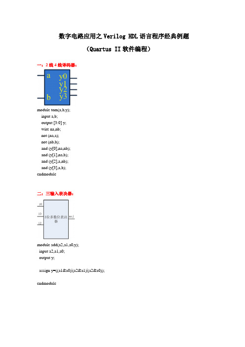
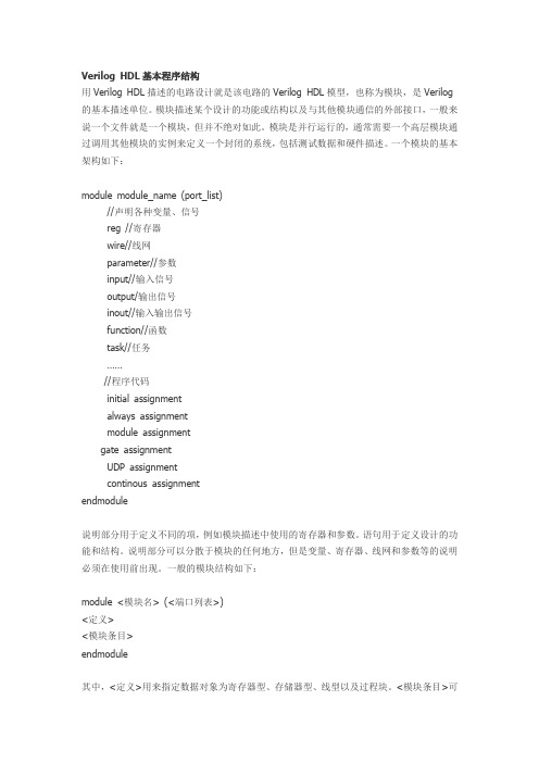
数字电路应用之Verilog HDL语言程序经典例题(Quartus II软件编程)一:2线4线译码器:module tom(a,b,y);input a,b;output [3:0] y;wire na,nb;not (na,a);not (nb,b);and (y[0],na,nb);and (y[1],na,b);and (y[2],a,nb);and (y[3],a,b);endmodule二:三输入表决器:module add(a2,a1,a0,y);input a2,a1,a0;output y;assign y=((a1&a0)|(a2&a1)|(a2&a0));endmodule三:3线8线译码器:module fulladd(a2,a1,a0,y);input a2,a1,a0;output [7:0] y;assign y[0]= ~( ~a2 & ~a1 & ~a0); assign y[1]= ~( ~a2 & ~a1 & a0); assign y[2]= ~( ~a2 & a1 & ~a0); assign y[3]= ~( ~a2 & a1 & a0); assign y[4]= ~( a2 & ~a1 & ~a0); assign y[5]= ~( a2 & ~a1 & a0); assign y[6]= ~( a2 & a1 & ~a0); assign y[7]= ~( a2 & a1 & a0);endmodule四:BIN2BCD码制转换:module fulladd(y,d,e);input [6:0] y;output [3:0] d,e;assign d=y/10;assign e=y%10;endmodule五:4位比较器:module tom(y,x,d);input [3:0] y,x;output [2:0] d;assign d[2]=(x>y)?1:0;assign d[1]=(x==y)?1:0;assign d[0]=(x<y)?1:0;endmodule六:四位全加器:法一:(调用程序法)module fulladd4(sum,c_in,c_out,a,b); output [3:0] sum;output c_out;input [3:0] a,b;input c_in;wire c1,c2,c3;fulladd fa0(sum[0],c1,a[0],b[0],c_in); fulladd fa1(sum[1],c2,a[1],b[1],c1); fulladd fa2(sum[2],c3,a[2],b[2],c2); fulladd fa3(sum[3],c_out,a[3],b[3],c3); endmodule//程序调用module fulladd(sum, c_out, a, b, c_in); output sum, c_out;input a, b, c_in;wire s1, c1, c2;xor (s1, a, b);and (c1, a, b);xor (sum, s1, c_in);and (c2, s1, c_in);xor (c_out, c2, c1);endmodule法二:(通用法)module fulladd4(A,B,Cin,SUM,Cout); input [3:0] A,B;input Cin;output [3:0] SUM;output Cout;assign {Cout,SUM}=A+B+Cin; endmodule七:七段显示译码器:法一:module bbc(a,d,g);input [3:0] a;output [6:0] d;output [3:0] g;reg [6:0] d;assign g=4'b0001;always @(a)begincase(a)4'b0000 :d=7'b100_0000;4'b0001 :d=7'b111_1001;4'b0010 :d=7'b010_0100;4'b0011 :d=7'b011_0000;4'b0100 :d=7'b001_1001;4'b0101 :d=7'b001_0010;4'b0110 :d=7'b000_0010;4'b0111 :d=7'b111_1000;4'b1000 :d=7'b000_0000;4'b1001 :d=7'b001_0000;default :d=7'b000_0000;endcaseendendmodule法二:module bbc(a,d,g);input [3:0] a;output [6:0] d;output [3:0] g;reg [6:0] d;assign g=4'b0001;always @(a)beginif (a==4'b0000) d=7'b100_0000;else if (a==4'b0001) d=7'b111_1001;else if (a==4'b0010) d=7'b010_0100;else if (a==4'b0011) d=7'b011_0000;else if (a==4'b0100) d=7'b001_1001;else if (a==4'b0101) d=7'b001_0010;else if (a==4'b0110) d=7'b000_0010;else if (a==4'b0111) d=7'b111_1000;else if (a==4'b1000) d=7'b000_0000;else if (a==4'b1001) d=7'b001_0000;else d=7'b000_0000; endendmodule八:8—3优先编码器:法一:module qq (y,d,g);input [7:0] y;output [2:0] d;output [3:0] g;reg [2:0] d;assign g=4'b0001;always @ ybeginif (y[7]==1) d=3'b111;else if (y[6]==1) d=3'b110;else if (y[5]==1) d=3'b101;else if (y[4]==1) d=3'b100;else if (y[3]==1) d=3'b011;else if (y[2]==1) d=3'b010;else if (y[1]==1) d=3'b001;else if (y[0]==1) d=3'b000;endendmodule法二:module encoder(none_on,outcode,a, b, c, d, e, f, g, h); output[2:0] outcode;output none_on;input a, b, c, d, e, f, g, h;reg[3:0] outtemp;assign {none_on, outcode} = outtemp;always @(a or b or c or d or e or f or g or h)begincasex ({a, b, c, d, e, f, g, h})8'B????_???1 : outtemp=4'b0_111;8'B????_??10 : outtemp=4'b0_110;8'B????_?100 : outtemp=4'b0_101;8'B????_1000 : outtemp=4'b0_100;8'B???1_0000 : outtemp=4'b0_011;8'B??10_0000 : outtemp=4'b0_010;8'B?100_0000 : outtemp=4'b0_001;8'B1000_0000 : outtemp=4'b0_000;8'B0000_0000 : outtemp=4'b1_000;endcaseendendmodule九:计数器:module bbc(clk,set,reset,d,y);input set,reset,clk;input [3:0] d;output [7:0] y;reg [7:0] y;always@(posedge clk or negedge reset or posedge set) if(~reset) y<=8'b0;else if (set) y[3:0]<=d[3:0];else y<=y+1'b1;endmodule十:移位寄存器:module asd (clk,set,reset,d,y,cin);input clk,set,reset,cin;input [3:0] d;output [7:0] y;reg [7:0] y;always@(posedge clk)beginif(~reset) y=0;else if(set)beginy[7:4]=y[3:0] ;y[3:0]=d[3:0];endelsebeginy=y<<1;y[0]=cin;endendendmodule十一:4位乘法:法一:module bbc(y,a,b);input [3:0] a;input [3:0] b;output [7:0] y;reg [7:0] y;reg[7:0] temp_a;reg[3:0] temp_b;integer i;always @(a or b)beginy=0;temp_a=a;temp_b=b;beginfor(i=0;i<=3;i=i+1)beginif(temp_b[0]) y=y+temp_a;temp_a=temp_a<<1;temp_b=temp_b>>1;endendendendmodule法二:module qq(outcome,a,b);output [8:1] outcome;input [4:1] a,b;reg [8:1] outcome;integer i;always@(a or b)beginoutcome=0;for(i=1;i<=4;i=i+1)if (b[1]) outcome=outcome + (a<<(i-1)); endendmodule十二:数码管跑马灯:module asd(cr,clk,a,b,c,d,e,f,g);input cr,clk;output a,b,c,d,e,f,g;reg a,b,c,d,e,f,g;integer i=0;always @ (posedge clk or negedge cr)beginif(~cr)begin{a,b,c,d,e,f,g}=7'b111_1111;i=0;endelse if(clk)begini=i+1;if(i==1) {a,b,c,d,e,f,g}=7'b011_1111;if(i==2) {a,b,c,d,e,f,g}=7'b101_1111;if(i==3) {a,b,c,d,e,f,g}=7'b110_1111;if(i==4) {a,b,c,d,e,f,g}=7'b111_0111;if(i==5) {a,b,c,d,e,f,g}=7'b111_1011;if(i==6) {a,b,c,d,e,f,g}=7'b111_1101;if(i==7) {a,b,c,d,e,f,g}=7'b111_1110;if(i==8) {a,b,c,d,e,f,g}=7'b000_0000;if(i==9)begin{a,b,c,d,e,f,g}=7'b111_1111;i=0;endendendendmodule十三:LED跑马灯:module add(cr,clk,y);input cr,clk;output [7:0] y;reg [7:0] y;integer i;always@(posedge clk or negedge cr) beginif(~cr)beginy=0;i=-1;endelse if (clk)begini=i+1;y=0;y[i]=1;beginif(i==7)i=-1;endendendendmodule。
veriloghdl程序大全

1.简单门电路的设计二输入与非门module nand_2(y,a,b);output y;input a,b;nand(y,a,b);endmodule二输入异或门module nand_2(y,a,b);output y;input a,b;reg y;always @(a,b)begincase({a,b})2’b00:y=1;2’b01:y=1;2’b10:y=1;2’b11:y=0;default:y=’bx;endcaseendendmodule二输入三态门module eda_santai(dout,din,en); output dout;input din,en;reg dout;alwaysif (en) dout<=din;else dout<=’bz;endmodule3-8译码器的设计module yimaqi(S1,S2,S3,A,Y); input S1;wire S1;input S2;wire S2;input S3;wire S3;input [2:0]A;wire [2:0]A;output[7:0]Y;reg [7:0]Y;reg s;always@(S,S1,S2,S3)begins<=S2|S3;Y <=8'b1111_1111;else if(S)Y <=8'b1111_1111;elsecase(A)3'b000:Y<=11111110;3'b001:Y<=11111101;3'b010:Y<=11111011;3'b011:Y<=11110111;3'b100:Y<=11101111;3'b101:Y<=11011111;3'b110:Y<=10111111;3'b111:Y<=01111111;endcaseendendmodule2.8-3编码器的设计module banjiaqi(a,b,count,sum);input a;wire a;input b;wire b;output count;wire count;output sum;wire sum;assign {count,sum}=a+b;endmodule4. D触发器的设计module Dchufaqi ( Q ,CLK ,RESET ,SET ,D ,Qn ); input CLK ;wire CLK ;input RESET ;wire RESET ;input SET ;wire SET ;input D ;wire D ;output Q ;reg Q ;output Qn ;wire Qn ;assign Qn = ~Q ;always @ ( posedge CLK or negedge SET or negedge RESET ) beginif ( !RESET)Q <= 0 ;else if ( ! SET)Q <= 1;else Q <= D;endendmodule5. 1位半加法器的设计module banjiafaqi(a,b,sum,count);input a;wire a;input b;wire b;output sum;wire sum;output count;wire count;assign {count,sum}=a+b;endmodule6. 4位计数器的设计module sihisjishuqi(CLK,RESET,out);input CLK;wire CLK;input RESET;wire RESET;output[3:0] out;reg[3:0] out;always @ ( posedge CLK or negedge RESET )beginif(!RESET)out<=4'b0000;elsebeginout<=out+1;if(out==4'b1010)out<=4'b0000;endendendmodule7.分频时序逻辑电路的设计module eda_fp_even(clk_out,clk_in,rst); input clk_in;input rst;wire rst;output clk_out;reg clk_out;reg [1:0]cnt;parameter N=6;always @(posedge clk_in or negedge rst) beginif(!rst)beginclk_out<=0;cnt<=0;endelsebegincnt<=cnt+1;if(cnt==N/2-1)beginclk_out=!clk_out;cnt<=0;endendendendmodule8.7段显示译码器的设计module eda_scan_seven(clk,dig,y,rst); input clk;wire clk;input rst;wire rst;output[7:0] dig;wire[7:0] dig;output [7:0]y;wire [7:0]y;reg clkout;reg [19:0]cnt;reg [2:0]wei;reg [3:0]duan;reg [6:0]Y_r;reg [7:0]dig_r;assign y = {1'b1,(~Y_r[6:0])};assign dig =~dig_r;parameter period= 1000000;always@(posedge clk or negedge rst) beginif(!rst)cnt<=0;else begincnt<=cnt+1;if(cnt==(period>>1)-1)clkout<=#1 1'b1;else if(cnt==period-1)beginclkout<=#1 1'b0;cnt<=#1 1'b0;endendendalways@(posedge clkout or negedge rst ) beginif(!rst)wei<=0;elsewei<=wei+1;endalways @(wei) //数码管选择begincase ( wei )3'b000 :begindig_r <= 8'b0000_0001;duan <= 1;end3'b001 :begindig_r <= 8'b0000_0010;duan<= 3;end3'b010 :begindig_r <= 8'b0000_0100;duan<= 5;end3'b011 :begindig_r <= 8'b0000_1000;duan <= 7;end3'b100 :begindig_r <= 8'b0001_0000;duan<= 9;end3'b101 :begindig_r <= 8'b0010_0000;duan<= 11;end3'b110 :begindig_r <= 8'b0100_0000;duan <= 13;end3'b111 :begindig_r <= 8'b1000_0000;duan<= 15;endendcaseendalways @ ( duan ) //译码begincase ( duan )0: Y_r = 7'b0111111; // 01: Y_r = 7'b0000110; // 12: Y_r = 7'b1011011; // 23: Y_r = 7'b1001111; // 34: Y_r = 7'b1100110; // 45: Y_r = 7'b1101101; // 56: Y_r = 7'b1111101; // 67: Y_r = 7'b0100111; // 78: Y_r = 7'b1111111; // 89: Y_r = 7'b1100111; // 910: Y_r = 7'b1110111; // A11: Y_r = 7'b1111100; // b12: Y_r = 7'b0111001; // c13: Y_r = 7'b1011110; // d14: Y_r = 7'b1111001; // E15: Y_r = 7'b1110001; // Fdefault: Y_r = 7'b0000000;endcaseendendmodule9.数据选择器的设计module eda_8xuanyi (A,D0,D1,D2,D3,D4,D5,D6,D7,G,Y); input D0,D1,D2,D3,D4,D5,D6,D7,G;input [2:0]A;wire [2:0]A;output Y;reg Y;always @(A, G)beginif (G==0)Y<=0;elsecase(A)3'b000:Y=D0;3'b001:Y=D1;3'b010:Y=D2;3'b011:Y=D3;3'b100:Y=D4;3'b101:Y=D5;3'b110:Y=D6;3'b111:Y=D7;endcaseendendmodule10.数据锁存器的设计module e da_suocunqi(q,d,oen,g); output[7:0] q;//数据输出端input[7:0] d;//数据输入端input oen,g;//三态控制端reg[7:0] q;always @(*)beginif (oen)beginq<="z";endelsebeginif(g)q<=d;elseq<=q;endendendmodule11.数据寄存器的设计module eda_jicunqi(r,clk,d,y); input r,clk;input [7:0]d;wire [7:0]d;output [7:0]y;reg [7:0]y;always @ (posedge clk or negedge r) beginif(!r)y<=8'b00000000;elsey<=d;endendmodule12.顺序脉冲发生器的设计module eda_shunxu(clk,clr,q);input clk,clr;output [7:0]q;reg [7:0]q;always @ ( posedge clk or posedge clr ) beginif ( clr==1)beginq<=8'b00000000; //赋初值endelsebeginif(q==0)q<=8'b00000001;elseq<=q<<1; //给初值进行移位endendendmodule13.1位全加法器的设计module quanjiaqi(a,b,sum,count,cin); input a;wire a;input b;wire b;input cin;wire cin;output sum;wire sum;output count;wire count;assign{sum,count}=a+b+cin; endmodule15.键控Led灯的设计module eda_led(led,key);input key;output led;reg led_out;assign led<=led_out;always@(key)beginif(key)led_out<=1;else if(!key)led_out<=0;endendmodule16.双向移位寄存器的设计module eda_yiweijicunqi( left_right ,load ,clr ,clk ,DIN ,DOUT );input left_right ;wire left_right ;input load ;wire load ;input clr ;wire clr ;input clk ;wire clk ;input [3:0] DIN ;wire [3:0] DIN ;output [3:0] DOUT ;wire [3:0] DOUT ;reg [3:0] data_r;assign DOUT = data_r ;always @ (posedge clk or posedge clr or posedge load)//敏感变量,看真值表beginif(clr==1)data_r <= 0;//判断是否清零else if (load )data_r<=DIN;//判断是否装载数据//判断进行左移位还是右移位elsebeginif(left_right)data_r<=DIN<<1;elsedata_r<=DIN>>1;endendendmodule17.8-3优先编码器的设计module youxianbianma( A ,I ,GS ,EO ,EI ); input [7:0] I ;wire [7:0] I ;input EI ;wire EI ;output [2:0] A ;reg [2:0] A ;output GS ;reg GS ;output EO ;reg EO ;always @ ( I or EI )if ( EI )beginA <= 3'b111;GS <= 1;EO <= 1;endelse if (I==8'b11111111)beginA <= 3'b111;GS <= 1;EO <= 0;endelse if ( I==8'b11111110 )beginA <= 3'b111;GS <= 0;EO <= 1;endelse if ( I==8'b1111110x )beginA <= 3'b110;GS <= 0;EO <= 1;endelse if ( I==8'b111110xx )beginA <= 3'b101;GS <= 0;EO <= 1;endelse if ( I==8'b11110xxx )beginA <= 3'b100;GS <= 0;EO <= 1;endelse if ( I==8'b1110xxxx )beginA <= 3'b011;GS <= 0;EO <= 1;endelse if ( I==8'b110xxxxx )beginA <= 3'b010;GS <= 0;EO <= 1;endelse if ( I==8'b10xxxxxx )beginA <= 3'b001;GS <= 0;EO <= 1;endelse if ( I==8'b0xxxxxxx )beginA <= 3'b000;GS <= 0;EO <= 1;endendmodule18.数据分配器的设计module shujufenpeiqi(y0,y1,y2,y3,din,a); output y0,y1,y2,y3;//4??êy?Yí¨μàinput din;//êy?Yê?è?input [1:0] a;reg y0,y1,y2,y3;always @(din,a)beginy0=0;y1=0;y2=0;y3=0; //3?ê??ˉ£á?case(a)00:y0=din;01:y1=din;02:y2=din;03:y3=din;endcase end endmodule。
Verilog HDL
Verilog HDL基本程序结构用Verilog HDL描述的电路设计就是该电路的Verilog HDL模型,也称为模块,是Verilog 的基本描述单位。
模块描述某个设计的功能或结构以及与其他模块通信的外部接口,一般来说一个文件就是一个模块,但并不绝对如此。
模块是并行运行的,通常需要一个高层模块通过调用其他模块的实例来定义一个封闭的系统,包括测试数据和硬件描述。
一个模块的基本架构如下:module module_name (port_list)//声明各种变量、信号reg //寄存器wire//线网parameter//参数input//输入信号output/输出信号inout//输入输出信号function//函数task//任务……//程序代码initial assignmentalways assignmentmodule assignmentgate assignmentUDP assignmentcontinous assignmentendmodule说明部分用于定义不同的项,例如模块描述中使用的寄存器和参数。
语句用于定义设计的功能和结构。
说明部分可以分散于模块的任何地方,但是变量、寄存器、线网和参数等的说明必须在使用前出现。
一般的模块结构如下:module <模块名> (<端口列表>)<定义><模块条目>endmodule其中,<定义>用来指定数据对象为寄存器型、存储器型、线型以及过程块。
<模块条目>可以是initial结构、always结构、连续赋值或模块实例。
下面给出一个简单的Verilog模块,实现了一个二选一选择器。
例2-1 二选一选择器(见图2-1)的Verilog实现图2-1 例2-1所示的二选一电路module muxtwo(out, a, b, s1);input a, b, s1;output out;reg out;always @ (s1 or a or b)if (!s1) out = a;else out = b;endmodule模块的名字是muxtwo,模块有4个端口:三个输入端口a、b和s1,一个输出端口out。
第三章 Verilog HDL的基本语法汇总
512个单元,每个单元为32位
3.3 Verilog HDL的运算符
算术运算符 逻辑运算符 关系运算符 等值运算符 位运算符 缩减运算符 移位运算符 条件运算符 拼接运算符
1.算术运算符
算术运算符包括: + (加法运算符或正值运算符,如x+y,+8) - (减法运算符或负值运算符,如x-y,-90) * (乘法运算符,如x*y) / (除法运算符,如x/y) % (取模运算符,如x % y)
1.间隔符: Verilog 的间隔符主要起分隔文本的作用,可以使 文本错落有致,便于阅读与修改。
间隔符包括空格符(\b)、TAB 键(\t)、换行符(\n)及 换页符。
2.注释符:注释只是为了改善程序的可读性,在编译时不起作用。 多行注释符(用于写多行注释): /* --- */; 单行注释符 :以//开始到行尾结束为注释文字。
3.标识符和关键词
标识符:给对象(如模块名、电路的输入与输出端口、变
量等)取名所用的字符串。以英文字母或下划线开始
如,clk、counter8、_net、bus_A 。
关键词:是Verilog语言本身规定的特殊字符串,用来定义 语言的结构。例如,module、endmodule、input、 output、wire、reg、and等都是关键词。关键词都是小 写,关键词不能作为标识符使用 。出始终根据输入的变化而 更新其值的变量,它一般指的是硬件电路中的各种物理 连接.
例:网络型变量L的值由与门的驱动信号 a和b所决定,即L=a&b。a、b的值发 生变化,线网L的值会立即跟着变化。
a
&L
Verilog语言基础知识
在Verilog HDL中,用parameter来定义常量,即用parameter来定义一个标志符,代表一个常量,称为符号常量。其定义格式如下:
parameter 参数名1=表达式,参数名2=表达式,参数名3=表达式……;
例如:
parameter sel=8,code=8'ha3;
//分别定义参数sel为常数8(十进制),参数code为常数a3(十六进制)
Verilog HDL中共有19种数据类型。数据类型是用来表示数字电路中的数据存储和传送单元的。在此介绍4个最基本的数据类型:integer型、parameter型、reg型和wire型。
Verilog HDL中也有常量和变量之分,他们分属以上这些类型。
6.2.1 常量
在程序运行过程中,其值不能被改变的量称为常量。
assign {cout,sum}=ina+inb+cin;//全加
endmodule
【例6.2】一个8位计数器的Verilog HDL源代码
module counter8(out,cout,data,load,cin,clk);
output[7:0]out;
output cout;
input[7:0] data;
6.1.2 Verilog HDL模块的结构
Verilog HDL的基本设计单元是"模块(block)"。一个模块是由两部分组成的,一部分描述接口;另一部分描述逻辑功能,即定义输入是如何影响输出的。下面举例说明,图6.1示出了一个"与-或-非"门电路。
图6.1"与-或-非"电路
该电路表示的逻辑函数可以写为:
6.2.2 变量
verilog程序运行原理

Verilog程序运行原理详解1. 引言Verilog是一种硬件描述语言,用于描述和设计数字电路。
在Verilog程序中,我们可以通过编写逻辑门等硬件元件的描述来实现电路的功能。
Verilog程序的运行原理涉及到编译、仿真和综合等多个步骤。
本文将详细解释这些步骤的基本原理,并对Verilog程序的运行过程进行全面、详细、完整和深入的探讨。
2. 编译编译是将Verilog程序翻译成计算机可以理解和执行的指令的过程。
Verilog程序通常包含模块定义、端口声明、信号声明、逻辑描述等部分。
2.1 模块定义在Verilog程序中,模块是描述电路功能的基本单元。
模块定义由关键字module 开始,后面跟着模块的名称和端口定义。
例如:module my_module(input A, input B, output C);// 逻辑描述endmodule2.2 端口声明模块的端口声明定义了输入和输出信号的名称和类型。
输入信号使用关键字input 声明,输出信号使用关键字output声明。
例如:module my_module(input A, input B, output C);// 逻辑描述endmodule2.3 信号声明信号声明定义了在模块中使用的内部信号的名称和类型。
信号可以是输入信号、输出信号或内部信号。
例如:module my_module(input A, input B, output C);wire D;// 逻辑描述endmodule2.4 逻辑描述逻辑描述部分包含了对电路功能的具体描述,通常使用逻辑门和时序元件的描述来实现。
例如:module my_module(input A, input B, output C);wire D;assign D = A & B;assign C = D;endmodule在编译过程中,编译器将对Verilog程序进行语法分析、词法分析和语义分析,生成对应的语法树和符号表。
VerilogHDL语言(PDF)

Verilog 讲义(二)1)续Verilog 基础2)Verilog 形为描述3.4 运算符九类运算符分类包含运算符算术运算符+ - * / %位运算符~ & | ^ ^~or~^缩位运算符& ~& | ~| ^ ^~or~^逻辑运算符! && ||关系运算符> < <= >=相等与全等运算符== != === !==逻辑移位运算符 <<>> 连接运算符 {}: 条件运算符 ?根据操作数的不同,又可分为三类:1)单目运算符只有一个操作数,且运算符位于操作数的左边如:~clk &a ~& 缩位运算符wire [7:0] aparity=^a (奇校验)2)双目运算符a+b a%b {a,b,c}3)三目运算符out=(sel)?a:b;运算符的优先级参:P443.4.1 算术运算符1)减法亦可用作单目运算符,取补运算2)除法运算符:整型类数据小数部分被截去: integer a=7/2=33)% 取余运算 7%2=13.4.2 位运算符1)~a 按位取反2)a&b 按位相与若a,b 位数不同,短的高位补0,(x者补x)3)^ ^~ 双目3.4.3 缩位运算符单目运算符,按位进行逻辑运算,结果产生一位的逻辑值。
A=4’b1001&a ~&a |a ~|a ^a ~^a0 1 1 0 1 0 3.4.3 逻辑运算符a&&b结果为一位的逻辑值若操作数为多位,只要有一位为1,整个操作数看作逻辑1;若有不定态,结果亦为不定态。
3.4.5关系运算符结果为一位的逻辑值。
3.4.6 相等与全等运算符结果为一位逻辑值相等:比较每一位,所有相等,关系满足,若有不定态或高阻态,不定态结果。
全等:与相等比较过程相同,亦将不定态及高阻态作为逻辑状态比较。
3.4.7 逻辑移位运算符<< >> 以0补位。
verilog程序
3-8 译码器module decoder_38(out,in);output[7:0] out;input[2:0] in;reg[7:0] out;always @(in)begincase(in)3'd0: out=8'b11111110;3'd1: out=8'b11111101;3'd2: out=8'b11111011;3'd3: out=8'b11110111;3'd4: out=8'b11101111;3'd5: out=8'b11011111;3'd6: out=8'b10111111;3'd7: out=8'b01111111;endcaseendendmodule3-8优先编码器module encoder8_3(none_on,outcode,a,b,c,d,e,f,g,h); output none_on;output[2:0] outcode;input a,b,c,d,e,f,g,h;reg[3:0] outtemp;assign {none_on,outcode}=outtemp;always @(a or b or c or d or e or f or g or h)beginif(h) outtemp=4'b0111;else if(g) outtemp=4'b0110;else if(f) outtemp=4'b0101;else if(e) outtemp=4'b0100;else if(d) outtemp=4'b0011;else if(c) outtemp=4'b0010;else if(b) outtemp=4'b0001;else if(a) outtemp=4'b0000;else outtemp=4'b1000;end基本D触发器endmodulemodule DFF(Q,D,CLK);output Q;input D,CLK;reg Q;always @(posedge CLK)beginQ <= D;end带异步清0、异步置1 的D 触发器endmodulemodule DFF1(q,qn,d,clk,set,reset);input d,clk,set,reset;output q,qn;reg q,qn;always @(posedge clk or negedge set or negedge reset) beginif (!reset) beginq <= 0; //异步清0,低电平有效qn <= 1;endelse if (!set) beginq <= 1; //异步置1,低电平有效qn <= 0;endelse beginq <= d;qn <= ~d;endendmodule4 位串并转换器module serial_pal(clk,reset,en,in,out);input clk,reset,en,in;output[3:0] out;reg[3:0] out;always @(posedge clk)beginif(reset) out<=4'h0;else if(en) out<={out,in}; //使用连接运算符endendmodule用for 语句描述的七人投票表决器module voter7(pass,vote);output pass;input[6:0] vote;reg[2:0] sum;integer i;reg pass;always @(vote)beginsum=0;for(i=0;i<=6;i=i+1) //for 语句if(vote[i]) sum=sum+1;if(sum[2]) pass=1; //若超过4 人赞成,则pass=1else pass=0;endendmodule模为60 的BCD 码加法计数器module count60(qout,cout,data,load,cin,reset,clk); output[7:0] qout;output cout;input[7:0] data;input load,cin,clk,reset;reg[7:0] qout;always @(posedge clk) //clk 上升沿时刻计数beginif (reset) qout<=0; //同步复位else if(load) qout<=data; //同步置数else if(cin)beginif(qout[3:0]==9) //低位是否为9,是则beginqout[3:0]<=0; //回0,并判断高位是否为5if (qout[7:4]==5) qout[7:4]<=0;elseqout[7:4]<=qout[7:4]+1; //高位不为5,则加1endelse //低位不为9,则加1qout[3:0]<=qout[3:0]+1;endendassign cout=((qout==8'h59)&cin)?1:0; //产生进位输出信号endmoduleCase实现的4选1数据选择器module mux4_1(out,in0,in1,in2,in3,sel);output out;input in0,in1,in2,in3;input[1:0] sel;reg out;always @(in0 or in1 or in2 or in3 or sel) //敏感信号列表case(sel)2'b00: out=in0;2'b01: out=in1;2'b10: out=in2;2'b11: out=in3;default: out=2'bx;endcaseEndmodule8位计数器module counter8 ( out,cout,data,load, cin,clk );output [7:0] out;output cout;input [7:0] data;input load, cin,clk ;reg[7:0] out;always @(posedge clk)beginif(load)out <= data; // 同步预置数据elseout < = out + 1 + cin; // 加1计数endassign cout = &out & cin; //若out为8‘hFF,cin为1,则cout为1 Endmodule比较器module compare(equal, a, b);input [1:0] a, b;output equal;assign equal =(a= =b)? 1:0;endmodule4位二进制加减计数器module counter(rst, clk, q , m);input rst, clk,m;output [3:0] q;reg [3:0] q;always @( posedge clk)if (!rst)q<=0;else if(m==0)if (q==15) q<=0; else q<=q+1;else if(m==1)if (q==0) q<=15; else q<=q-1;endmodule4位BCD码加减计数器module counter(rst, clk, q , m);input rst, clk,m;output [3:0] q;reg [3:0] q;always @( posedge clk)if (!rst)q<=0;else if(m==0)if (q==9) q<=0; else q<=q+1; else if(m==1)if (q==0) q<=9; else q<=q-1; endmodule。
1、VerilogHDL设计流程
1、VerilogHDL设计流程1、Verilog HDL 设计流程:1、文本编辑:文件保存为.v的文件;2、功能仿真:将.v文件调入HDL仿真软件,逻辑功能是否正确(前仿真);3、逻辑综合:将源文件调入逻辑综合软件进行综合,把语言综合成最简的布尔表达式,生成.edf的EDA工业标准文件;矚慫润厲钐瘗睞枥庑赖。
4、布局布线;5、时序仿真:验证电路的时序(后仿真)。
2、Verilog 程序包括四部分:1、端口定义2、I/O口说明3、内部信号声明4、功能定义3、逻辑功能定义:三种方法在模块中产生逻辑:(1)用assign 声明语句;如assign a = b & c;(描述组合逻辑)(2)用实例元件;如and #2 u1(q,a,b);(3)用always块;如(既可描述组合逻辑也可描述时序逻辑)always @ (posedge clk or posedge clr)beginif(clr) q <= 0;else if(en) q <= d;end4、网络类型变量两种:wire triWire型变量:用来表示单个门驱动或连续赋值语句驱动的网络类型数据。
Tri 型变量:用来表示多驱动器驱动的网络型数据。
线网类型两种:wire triTri 主要用于定义三态的线网;Wire型:代表的是物理连接,不存储逻辑值,要由器件驱动,通常用assign进行赋值Wire类型的信号没被驱动,缺省值为Z(高阻);信号没有定义数据类型时,缺省为wire 类型。
(缺省==默认)聞創沟燴鐺險爱氇谴净。
Reg型:默认初始值为x,通常用always模块内的指定信号,常代表触发器;always模块内被赋值的每一个信号都必须定义为reg型。
(寄存器类型)Verilog HDL 有5种寄存器类型:reg、integer、time、real、realtime5、运算符号所带操作数单目运算符:可带一个操作数,操作数放在运算符右边双目运算符:可带两个操作数,操作数放在运算符两边三目运算符:可带3个操作数,用三目运算符分隔开6、底层模块的调用:底层模块(被测试模块)可由测试模块调用如:(位置关联方式) :AND_G2 AND_G2(A,B,F);第一个AND_G2 为底层模块名,第二个为实例名,(A,B,F)为参数定义。
VerilogHDL基本语法
c a b
源程序如下
1
&
&
&
out
module example_2_3 out,a,b,c ;
input
a,b,c;
output out;
assign out = a b:c;
endmodule
ห้องสมุดไป่ตู้
9. 位并接操作符 Concatenation operators 并接操作符为:{} 并接操作符的使用格式: {操作数1的某些位,操作数2的某些位,…,操作数n的某 些位};
⑤ 可以用/*……*/或//……对Verilog HDL程序的任 何部分作注释。
一个完整的源程序都应当加上需要的注释,以 加强程序的可读性。
2.2 Verilog HDL的词法
2.2.1 空白符和注释
Verilog HDL的空白符包括空格、tab符号、换行 和换页。
空白符如果不是出现在字符串中,编译源程序时 将被忽略。
input
端口1,端口2,端口3,…;
output
端口1,端口2,端口3,…;
例如
input
ina,inb,cin;
output
sum,cont;
2. 信号类型声明
信号类型声明用来说明设计电路的功能描述中,所用的 信号的数据类型以及函数声明。
信号的数据类型主要有连线 wire 、寄存器 reg 、整型 integer 、实型 real 和时间 time 等类型。
8. 条件操作符 Conditional operators 条件操作符为: :
条件操作符的操作数有3个,其使用格式为 操作数 = 条件 表达式1:表达式2;
即当条件为真 条件结果值为1 时,操作数 = 表达 式1;为假 条件结果值为0 时,操作数 = 表达式2。
Verilog程序的基本结构

2、每个模块先要进行端口的定义,并说明输入(input)和输出 (output),然后对模块功能进行描述。
3、除了endmodule语句外,每个语句后必须有分号。 4、可以用/* --- */和//…..对程序的任何部分做注释。
S
B
U4
D
U3
端口类型说明
wire Snot, A, B ; //定义内部节点信号数据类型 //下面对电路的逻辑功能进行描述
数据类 型说明
not U1(Snot, Sl);
and U2(A, D0, Snot);
and U3(B, D1, S); or U4(Y, A, B);
电路结构描述
endmodule
数据类 型说明
always @(S or D0 or D1) if (S == 1) Y = D1; //也可以写成 if (S) Y = D1; else Y = D0; //注意表达式左边的Y必须是reg型
endmodule
实Байду номын сангаас化低层模块和基本门级元件; 连续赋值语句(assign); 过程块结构(initial和always)
行为描述语句;
endmodule
逻辑功能描 述部分,其 顺序是任意的
例 用结构描述方式建立门电路Verilog模型
模块名
D0 Snot
A
U2
U1
Y
module mux2to1(D0, D1, S, Y ); input D0, D1, S; //定义输入信号 output Y; //定义输出信号
verilog语言及程序设计

verilog语言及程序设计Verilog语言及程序设计什么是Verilog语言?Verilog是一种硬件描述语言(HDL),用于描述数字系统的行为和结构。
它最初是由Gateway Design Automation公司(现在是Cadenza Design Automation公司的一部分)于1984年开发的,用于模拟和验证集成电路设计。
Verilog不仅可以用于模拟和验证电路设计,还可以用于编写可综合的硬件描述。
可综合的硬件描述可以通过合成工具转换成实际的硬件电路,在FPGA(现场可编程门阵列)和ASIC(应用特定集成电路)中实现。
Verilog的应用领域Verilog广泛应用于数字系统的设计、验证和实现。
它可以用于设计各种数字电路,包括处理器、存储器、通信接口、数字信号处理器等。
Verilog还被用于编写可综合的程序,用于验证电路设计的正确性。
Verilog的基本语法Verilog语言的基本语法与C语言类似,包括模块定义、端口声明、信号声明、组合逻辑、时序逻辑等。
下面是一个简单的Verilog模块的例子:verilogmodule MyModule (input wire clk,input wire rst,input wire in_data,output wire out_data);reg [7:0] reg1;always (posedge clk or posedge rst) beginif (rst)reg1 <= 8'b0;elsereg1 <= reg1 + in_data;endassign out_data = reg1;endmodule上面的例子定义了一个名为`MyModule`的Verilog模块,有4个端口:`clk`(时钟),`rst`(复位),`in_data`(输入数据),`out_data`(输出数据)。
其中的`reg1`是一个8位的寄存器,使用时序逻辑进行更新。
硬件描述语言VerilogHDL基础

入zz x x x
CSLG
4、设计举例
试用Verilog语言的门级 元件描述2线-4线译码器.
E1
& Y0
//Gate-level description of a 2-to-4-
line decoder
module _2to4decoder (A1,A0,E,Y);
input A,B,E;
output [3:0] Y;
常量
格式为:<+/-><位宽>’<基数符号><数 例值如>:3’b101、5’o37、8’he3,8’b1001_0011
实数型常量 十进制记数法 如: 0.1、2.0、5.67
科学记数法 如: 23_5.1e2、5E-4
23510.0、 0.0005
CSLG
❖Verilog允许用参数定义语句定义一个标识 符来代表一个常量,称为符号常量。
CSLG
CSLG
用Verilog HDL描述组合逻辑电路
用VerilogHDL描述组合逻辑电路
❖用VerilogHDL描述组合逻辑电路有三种不 同抽象级别:
▪ 门级描述 ▪ 数据流描述 ▪ 行为级描述
❖VerilogHDL描述的电路就是该电路的 VerilogHDL模型。
CSLG
•门级描述:
一般使用Primitive(内部元件)、自定义的下层模块对电 路描述。主要用于层次化设计中。
多输入端的或非门
多输入端的异或非门
多输出端的反相器
控制信号高电平有效的 三态反相器
控制信号低电平有效的 三态反相器
CSLG
Verilog 基本门级元件
and n-input AND gate
硬件描述语言verilog_HDL基础

12
1.4 Verilog 目前的应用情况和适用的设计
Verilog 较为适合系统级(System)、算法 级(Alogrithem)、寄存器传输级(RTL)、逻辑 (Logic)、门级(Gate)和电路开关级(Switch)的
设计,而对于特大型(千万门级以上)的系 统级(System)设计,则VHDL更为合适。
2020/2/28
13
1.5 采用 Verilog HDL 设计复杂数字电路的优点
1.5.1 传统设计方法——电路原理图输入法
采用电路原理图输入法进行设计,周期长、需 要专门的设计工具、需手工布线等。这种低水平的 设计方法大大延长了设计周期。
2020/2/28
14
1.5.2 Verilog HDL 设计法与传统的电路 原理图输入法的比较
2020/2/28
3
什么是硬件描述语言
具有特殊结构能够对硬件逻辑电路的功能进行描述的一种高级 编程语言
这种特殊结构能够:
描述电路的连接 描述电路的功能 在不同抽象级上描述电路 描述电路的时序 表达具有并行性
HDL主要有两种:Verilog和VHDL
Verilog起源于C语言,因此非常类似于C语言,容易掌握 VHDL格式严谨 VHDL出现较晚,但标准化早。IEEE 1706-1985标准。
2020/2/28
24
概述
Verilog HDL行为描述语言具有以下功能:
• 可描述顺序执行或并行执行的程序结构。 • 用延迟表达式或事件表达式来明确地控制过程的启动时间。 • 通过命名的事件来触发其它过程里的激活行为或停止行为。 • 提供了条件如if-else、case、循环程序结构。 • 提供了可带参数且非零延续时间的任务(task)程序结构。 • 提供了可定义新的操作符的函数结构(function)。 • 提供了用于建立表达式的算术运算符、逻辑运算符、位运算 符。 • Verilog HDL语言作为一种结构化的语言也非常适合于门级 和开关级的模型设计。
verilog入门基础教程
5.常量及其表示 . 整数型 十进制数的形式的表示方法:表示有符号常量 十进制数的形式的表示方法:表示有符号常量 例如:30、- 、-2 例如:30、-2 带基数的形式的表示方法: 表示常量 带基数的形式的表示方法: 表示常量 格式为: ><位宽 <基数符号><数值> 位宽> ><数值 格式为:<+/-><位宽>’<基数符号><数值> 例如: 例如:3’b101、5’o37、8’he3,8’b1001_0011 、 、 , 0.1、2.0、 十进制记数法 如: 0.1、2.0、5.67 科学记数法 如: 23_5.1e2、5E-4 、 -
ቤተ መጻሕፍቲ ባይዱ
3.常用 常用VHDL与Verilog两种语言的比较 与 两种语言的比较 常用
能力( 能力(capability) ) VHDL 结构建模 抽象能力强 系统级-算法级- 系统级-算法级-RTL级-逻辑级-门级 级 逻辑级- Verilog 结构建模 具体物理建模能力强 算法级- 算法级-RTL级-逻辑级-门级-版图级 级 逻辑级-门级-
2.3.1 Verilog语言的基本语法规则 语言的基本语法规则
为对数字电路进行描述, 语言规定了一套完整的语法结构。 为对数字电路进行描述,Verilog语言规定了一套完整的语法结构。 语言规定了一套完整的语法结构 的间隔符主要起分隔文本的作用, 1.间隔符: Verilog 的间隔符主要起分隔文本的作用,可以 间隔符 使文本错落有致,便于阅读与修改。 使文本错落有致,便于阅读与修改。 间隔符包括空格符( )、 )、换行符 换行符( 间隔符包括空格符(\b)、TAB 键(\t)、换行符(\n)及 换页符。 换页符。 2.注释符:注释只是为了改善程序的可读性,在编译时不起作用。 注释符:注释只是为了改善程序的可读性,在编译时不起作用。 多行注释符(用于写多行注释): */; 多行注释符(用于写多行注释): /* --- */; //开始到行尾结束为注释文字 开始到行尾结束为注释文字。 单行注释符 :以//开始到行尾结束为注释文字。
verilog语言及程序设计
verilog语言及程序设计Verilog语言及程序设计1. 引言Verilog语言是一种硬件描述语言(HDL),它被广泛应用于数字逻辑设计和硬件工程中。
本文将介绍Verilog语言的基本概念、语法和程序设计方法,帮助读者了解和掌握Verilog语言的使用。
2. Verilog语言基础2.1 Verilog语言概述Verilog语言是一种用于描述数字系统的硬件描述语言。
它提供了一种高级抽象的方式来描述和设计数字电路。
Verilog代码可以表示电路的结构、功能和时序,方便设计和验证数字系统。
2.2 Verilog的数据类型Verilog语言支持多种数据类型,包括基本数据类型和派生数据类型。
常用的基本数据类型包括整型、实型和布尔型。
派生数据类型包括数组、结构体和联合体等。
2.3 Verilog的模块化设计Verilog语言的模块化设计使得电路的设计和验证更加灵活和高效。
模块是Verilog代码的基本组织单元,可以嵌套使用,方便进行模块的重用和层次化设计。
2.4 Verilog的时序建模Verilog语言支持时序建模,可以描述数字逻辑电路中的时序关系和时钟控制。
通过时钟信号和触发器的使用,可以实现各种时序逻辑功能。
3. Verilog程序设计3.1 Verilog的模块定义在Verilog语言中,可以通过module关键字定义一个模块。
模块由输入输出端口和内部逻辑组成。
模块可以根据需要进行参数化,方便在不同设计场景中的复用。
verilogmodule my_module(input wire clk,input wire rst,input wire [7:0] data_in,output wire [7:0] data_out);// 内部逻辑//endmodule3.2 Verilog的时序建模Verilog语言提供了多种时序建模的方法,包括组合逻辑、时钟触发器、时钟边沿触发器等。
通过适当的时序建模,可以准确描述数字电路中的时序关系。
VERILOGHDL语言基础

VERILOGHDL语⾔基础第1节 Verilog HDL语⾔简介Verilog HDL语⾔简介Verilog HDL和VHDL是⽬前世界上最流⾏的两种硬件描述语⾔(HDL:Hardware Description Language),均为IEEE标准,被⼴泛地应⽤于基于可编程逻辑器件的项⽬开发。
⼆者都是在20世纪80年代中期开发出来的,前者由Gateway Design Automation公司(该公司于1989年被Cadence公司收购)开发,后者由美国军⽅研发。
HDL语⾔以⽂本形式来描述数字系统硬件结构和⾏为,是⼀种⽤形式化⽅法来描述数字电路和系统的语⾔,可以从上层到下层来逐层描述⾃⼰的设计思想。
即⽤⼀系列分层次的模块来表⽰复杂的数字系统,并逐层进⾏验证仿真,再把具体的模块组合由综合⼯具转化成门级⽹表,接下去再利⽤布局布线⼯具把⽹表转化为具体电路结构的实现。
⽬前,这种⾃顶向下的⽅法已被⼴泛使⽤。
概括地讲,HDL语⾔包含以下主要特征:* HDL语⾔既包含⼀些⾼级程序设计语⾔的结构形式,同时也兼顾描述硬件线路连接的具体结构。
* 通过使⽤结构级⾏为描述,可以在不同的抽象层次描述设计。
HDL语⾔采⽤⾃顶向下的数字电路设计⽅法,主要包括3个领域5个抽象层次。
* HDL语⾔是并⾏处理的,具有同⼀时刻执⾏多任务的能⼒。
这和⼀般⾼级设计语⾔(例如C 语⾔等)串⾏执⾏的特征是不同的。
* HDL语⾔具有时序的概念。
⼀般的⾼级编程语⾔是没有时序概念的,但在硬件电路中从输⼊到输出总是有延时存在的,为了描述这⼀特征,需要引⼊时延的概念。
HDL语⾔不仅可以描述硬件电路的功能,还可以描述电路的时序。
2.1.1 Verilog HDL语⾔的历史1983年,Gateway Design Automation(GDA)硬件描述语⾔公司的Philip Moorby⾸创了Verilog HDL。
后来Moorby成为Verilog HDL-XL的主要设计者和Cadence公司的第⼀合伙⼈。
10第三章verilog入门

算术运算符
关系运算符 (双目运算符)
位运算符 (双目运算符)
~ & | ^ ^~ 或 ~^ ! && || {,} {{}}
按位取反 按位与 按位或 按位异或 按位同或 逻辑非 逻辑与 逻辑或 将多个操作数 拼接成为一个 操作数
缩位运算符( 单目运算符)
逻辑运算符 (双目运算符)
移位运算符( 双目运算符) 条件运算符( 三目运算符)
条件语句
根据条件表达式的真假, 确定下一步进行的运算。
(1) if (condition_expr) true_statement;
(2) if (condition_expr)true_statement; else fale_ statement;
(3) if (condition_expr1) true_statement1; else if (condition_expr2) true_statement2; else if (condition_expr3) true_statement3; …… else default_statement;
一、硬件描述语言 Verilog HDL 基础
1. 什么是硬件描述语言
HDL:Hardware Description Language
逻辑电路图 表示 逻辑表达式 复杂数字逻辑系统 易于存储和修改 编写说明文档 不同设计人员交流 被计算机识别 类似于高级 程序设计语 言的文本形 式来描述数 字系统硬件 的结构和行 为的语言。 逻辑仿真 逻辑综合
3. Verilog的基本语法规则
运算符
类型 符号 + * / 功能说明 二进制加 二进制减 2的补码 二进制乘 二进制除 类型 符号 > < >= <= == != & ~& | ~| ^ ^~ 或 ~^ >> << ?: 功能说明 大于 小于 大于或等于 小于或等于 相等 不相等 缩位与 缩位与非 缩位或 缩位或非 缩位异或 缩位同或 右移 左移 根据条件表达 式是否成立,选择 表达式
verilog基本语句

verilog基本语句Verilog是一种硬件描述语言,旨在描述数字电路和系统的行为和结构。
在Verilog中,有一些基本的语句被广泛使用,可以用来编写并实现数字系统的行为。
下面我们来看一些常见的Verilog基本语句。
模块定义语句:模块是Verilog程序的基本单位,定义了数字系统的行为和结构。
模块定义语句用来定义模块的输入输出端口以及内部的行为和结构。
示例:module mymodule(input port1,output port2);//此处定义模块的内部行为和结构endmodule输入输出语句:在模块中需要定义输入输出端口,输入输出语句用来定义模块的输入和输出端口。
示例:input port1;output port2;赋值语句:赋值语句用来给变量赋值,可以用下划线和等号两种方式进行赋值,下划线表示连续多位赋值,等号表示单个位赋值。
示例:wire [7:0] data;assign data[7:0] = 8'b10101100;assign data = 8'b10101100;if条件语句:if条件语句用来表示条件判断,并根据判断结果执行相应的操作。
示例:if (port1 == 1'b1) begin//执行操作1endelse begin//执行操作2endcase语句:case语句用来表示多条件判断,并根据不同的条件执行相应的操作。
示例:case (address)4'h0: //执行操作14'h1: //执行操作24'h2: //执行操作3default: //执行操作4endcase循环语句:循环语句用来表示循环操作,包括for循环和while循环两种方式。
示例:for (i = 0; i < 8; i=i+1) begin//执行循环操作endwhile (port1 == 1'b1) begin//执行循环操作end以上就是常见的Verilog基本语句,它们可以用来描述数字系统的行为和结构,并实现对数字系统的控制和操作。
- 1、下载文档前请自行甄别文档内容的完整性,平台不提供额外的编辑、内容补充、找答案等附加服务。
- 2、"仅部分预览"的文档,不可在线预览部分如存在完整性等问题,可反馈申请退款(可完整预览的文档不适用该条件!)。
- 3、如文档侵犯您的权益,请联系客服反馈,我们会尽快为您处理(人工客服工作时间:9:00-18:30)。
1.设计一个产生010*******的序列信号发生器。
module generator(out,clk,state);output [3:0]state;output out;input clk;reg [3:0]state;reg out;always@(posedge clk)beginif(state==9)state<=0;elsestate<=state+1;case(state)4'b0000:out<=0;4'b0001:out<=1;4'b0010:out<=0;4'b0011:out<=0;4'b0100:out<=1;4'b0101:out<=0;4'b0110:out<=0;4'b0111:out<=1;4'b1000:out<=1;4'b1001:out<=1;default:out<=0;endcaseendendmodule2.设计一个8位的加减计数器。
时钟信号为clk,同步清零信号为rst。
Clk上升沿时刻,当inc=1计数器加二,其他情况计数器保持不变。
module counter(rst,clk,q,inc,dec);input rst,clk,inc,dec;output [7:0]q;reg [7:0]q;always@(posedge clk)if(rst)q<=0;elsecase({inc,dec})2'b10:begin if(q==254) q<=0;else q<=q+2;end//2'b01:begin if(q==0) q<=254;else q<=q-2;end//default:q<=q;endcaseendmodule3.序列检测器(移位寄存器法)11111010000序列检测器module shift(q,s,d,clk);input clk,d;output [10:0]q;output s;reg[10:0]q;reg s;always@(posedge clk)beginq<=q<<1;q[0]<=d;endalways@(posedge clk)if(q==11'b11111010000)s<=1;else s<=0;endmodule11111010000序列检测器(状态机)module shift1 (x,z,rst,clk,state);input x,rst,clk;output z;output[3:0]state;wire z;reg[3:0] state;parameters0=4'b0000,s1=4'b0001,s2=4'b0010,s3=4'b0011,s4=4'b0100,s5=4'b 0101,s6=4'b0110,s7=4'b0111,s8=4'b1000,s9=4'b1001,s10=4'b1010; assign z=(state==s10 && x==0)?1:0;always@(posedge clk or negedge rst)if(!rst)state<=s0;elsecase(state)s0: if(x==1) state<=s1;else state<=s0;s1: if(x==1) state<=s2;else state<=s0;s2: if(x==1) state<=s3;else state<=s0;s3: if(x==1) state<=s4; else state<=s0;s4: if(x==1) state<=s5; else state<=s0;s5: if(x==0) state<=s6; else state<=s5;s6: if(x==1) state<=s7; else state<=s0;s7: if(x==0) state<=s8; else state<=s2;s8: if(x==0) state<=s9; else state<=s1;s9: if(x==0) state<=s10; else state<=s1;s10: if(x==0) state<=s0; else state<=s1; default: state<=s0; endcase endmoduleVerilog设计一个为16*4的RAMmodule mymem (data, addr, read, write);inout [3:0] data;input [3:0] addr;input read, write;reg [3:0] memory [0:15]; // 16*4// 读assign data = read ? memory[addr] : 4'bz; // 写always @( posedge write)memory[addr] = data; endmodule1KB的RAMmodule ram1kB (data, addr, read, write); inout [7:0] data;input [9:0] addr;input read, write;reg [7:0] memory [0:1023]; // 16*4// 读assign data = read ? memory[addr] : 8'bz;// 写always @( posedge write)memory[addr]<=data;endmoduleROM在下面的例子中,给出如何定义一个字长和地址均参数化的只读存储器件module scalable_ROM (mem_word, address);parameter addr_bits = 8; // 地址总线宽度parameter wordsize = 8; // 字宽parameter words = (1 << addr_bits); // mem容量output [wordsize:1] mem_word; // 存储器字input [addr_bits:1] address; // 地址总线reg [wordsize:1] mem [0 : words-1]; // mem声明// 输出存储器的一个字wire [wordsize:1] mem_word = mem[address];endmodule例中存储器字范围从0而不是1开始,因为存储器直接用地址线确定地址。
也可以用下面的方式声明存储器并寻址。
reg [wordsize:1] mem [1:words]; // 从地址1开始的存储器// 存储器寻址时地址必须加1wire [wordsize:1] mem_word = mem[ address + 1];∙小时光∙消息(1)∙∙∙新闻∙网页∙贴吧∙知道∙音乐∙图片∙视频∙地图∙百科∙文库∙经验首页问题分类∙经济金融∙企业管理∙法律法规∙社会民生∙科学教育∙健康生活∙体育运动∙文化艺术∙电子数码∙电脑网络∙娱乐休闲∙地区∙心理分析∙医疗卫生∙资源共享知道栏目∙知道日报∙真相问答机∙知道大数据知道用户∙芝麻∙芝麻团∙芝麻将∙财富商城∙知道之星∙知道活动咨询专家∙高质量问答∙知道行家∙问医生∙作业帮∙宝宝知道经验∙开放平台∙手机知道∙个人中心急求一个verilog编写的异步串行通信的程序,最好有校验位,459785950@。
答的好可以再加分提问者采纳moduleasyn(clk,rst,wr,wr_bit,addr,bit_in,data_in,t1_ow,rxd,txd,intr,data_out,pcon,sco n,rx_sbuf);input clk;input rst;input wr;input wr_bit;input [7:0] addr;input bit_in;input [7:0] data_in;input t1_ow;input rxd;output txd;output intr;output [7:0] data_out;output [7:0] scon;output [7:0] pcon;output [7:0] rx_sbuf;reg txd;reg [7:0] scon;reg [7:0] pcon;assign intr=scon[1]|scon[0];//wire t1_ow_final;reg div2_flag;reg t1_ow_buf;reg t1_ow_final_buf;// signals with transmit partreg [7:0] tx_sbuf;reg send_n; //active low,indicate that it is transmiting dataswire wr_sbuf_en;assign wr_sbuf_en=(wr==1'b1&&addr==8'h99);reg wr_sbuf_en_mem;wire shift_en;reg [3:0] tx_next_state;reg [3:0] tx_current_state;parameterIDLE=11,START=0,D0=1,D1=2,D2=3,D3=4,D4=5,D5=6,D6=7,D7=8,TB8_BIT =9,STOP_BIT=10; //states definereg [3:0] osc_cnt;reg [3:0] tx_sample_cnt;reg tx_clk;//signals with receive partreg [3:0] rx_next_state;reg [3:0] rx_current_state;reg [3:0] rx_sample_cnt;wire one_bit;reg rxd_buf;reg [10:0] sbuf_rxd_tmp;reg [7:0] rx_sbuf;reg sample_7,sample_8,sample_9;reg receive;//signals with both transmiting and receiving parts//always @(*)//begin//SM0=scon[7];//SM1=scon[6];//SM2=scon[5];//REN=scon[4];//TB8=scon[3];//RB8=scon[2];//TI=scon[1];//RI=scon[0];//endalways @(posedge clk or posedge rst) //register scon beginif (rst)scon <=8'b0100_0000;else if ((wr) & !(wr_bit) & (addr==8'h98))scon <=data_in;else if ((wr) & (wr_bit) & (addr[7:3]==5'b10011))scon[addr[2:0]]<=bit_in;else if (tx_next_state==STOP_BIT)scon[1] <=1'b1;elsecase(rx_next_state)START:scon[0]<=1'b0;IDLE:if(rx_current_state==STOP_BIT)begincase (scon[7:6])2'b00: scon[0] <= 1'b1;2'b01: if(scon[5])if(one_bit)scon[0] <= 1'b1;elsescon[0] <= 1'b0;elsescon[0] <= 1'b1;2'b10,2'b11: if(scon[5])scon[0]<=sbuf_rxd_tmp[9];elsescon[0]=1'b1;endcaseendendcaseend////power control register//wire smod;assign smod = pcon[7];always @(posedge clk or posedge rst)beginif (rst)pcon <= 8'b0000_0000;else if ((addr==8'h87) & (wr) & !(wr_bit))pcon <= data_in;endalways @(posedge clk or posedge rst) //osc_cntif(rst)osc_cnt<=4'b0000;else if(osc_cnt==4'b1011)osc_cnt<=4'b0000;elseosc_cnt<=osc_cnt+1'b1;always @(posedge clk or posedge rst) //t1_ow_buf if(rst)t1_ow_buf<=1'b0;else if(t1_ow)t1_ow_buf<=~t1_ow;always @(posedge clk or posedge rst) //div2_flagif(rst)div2_flag<=1'b0;else if(~t1_ow_buf&t1_ow)div2_flag<=~div2_flag;assign t1_ow_final=(pcon[7]==1'b1)?t1_ow:t1_ow&div2_flag;//transmit partalways @(posedge clk or posedge rst) //t1_ow_final_bufif(rst) t1_ow_final_buf<=1'b0;else t1_ow_final_buf<=t1_ow_final;always @(posedge clk or posedge rst) //tx_sample_cntif(rst)begintx_sample_cnt<=4'b0000;endelse if(t1_ow_final_buf==1'b0&&t1_ow_final==1'b1)tx_sample_cnt<=tx_sample_cnt+1'b1;always @(posedge clk or posedge rst)if(rst)wr_sbuf_en_mem<=1'b0;else if (wr_sbuf_en&&wr_sbuf_en_mem<=1'b0)wr_sbuf_en_mem<=1'b1; //represent that the tx_sbuf has been loadedelse if(tx_current_state==STOP_BIT)wr_sbuf_en_mem<=1'b0;assignshift_en=wr_sbuf_en_mem==1'b1&&tx_sample_cnt==4'b1111&&osc_cnt==4' b1011&&t1_ow_final_buf==1'b0&&t1_ow_final==1'b1;always @(posedge clk or posedge rst)if(rst)tx_sbuf<=8'b0000_0000;else if (wr_sbuf_en&&wr_sbuf_en_mem<=1'b0)tx_sbuf<=data_in;else if(send_n==1'b0&&shift_en)tx_sbuf<=tx_sbuf>>1'b1;//the three always phrase below is the 3 parts discription of state machinealways @(*)//(tx_current_state or wr_sbuf_en_mem or tx_sample_cnt or osc_cnt or TH1 or TL1 or shift_en)begincase(tx_current_state)IDLE: if(shift_en) //tx_next_state=START;elsetx_next_state= IDLE;START:if(shift_en)tx_next_state=D0;elsetx_next_state=START;D0: if(shift_en)tx_next_state=D1;elsetx_next_state=D0;D1: if(shift_en)tx_next_state=D2;elsetx_next_state=D1;D2: if(shift_en)tx_next_state=D3;elsetx_next_state=D2;D3: if(shift_en)tx_next_state=D4;elsetx_next_state=D3;D4: if(shift_en)tx_next_state=D5;elsetx_next_state=D4;D5: if(shift_en)tx_next_state=D6;elsetx_next_state=D5;D6: if(shift_en)tx_next_state=D7;elsetx_next_state=D6;D7: if(shift_en)if(scon[7:6]==2'b00||scon[7:6]==2'b01)tx_next_state=STOP_BIT;elsetx_next_state=TB8_BIT;elsetx_next_state=D7;TB8_BIT: tx_next_state=STOP_BIT;STOP_BIT:if(tx_sample_cnt==4'b1111&&osc_cnt==4'b1011&&t1_ow_final==1'b1) tx_next_state=IDLE;elsetx_next_state=STOP_BIT;default:tx_next_state=IDLE;endcaseendalways @(posedge clk or posedge rst) if(rst)tx_current_state<=IDLE;elsetx_current_state<=tx_next_state;always @(posedge clk or posedge rst) if(rst)begintxd<=1'b1;send_n<=1'b1;endelsecase(tx_next_state)IDLE:beginsend_n<=1'b1;txd<=1'b1;endSTART:beginsend_n<=1'b0;txd<=1'b0;endD0: txd<=tx_sbuf[0];D1: txd<=tx_sbuf[0];D2: txd<=tx_sbuf[0];D3: txd<=tx_sbuf[0];D4: txd<=tx_sbuf[0];D5: txd<=tx_sbuf[0];D6: txd<=tx_sbuf[0];D7: txd<=tx_sbuf[0];TB8_BIT: txd<=scon[3];STOP_BIT:begintxd<=1'b1;endendcase//receiving partassignrx_shift_en=rx_sample_cnt==4'b1111&&t1_ow_final_buf==1'b0&&t1_ow_final ==1'b1;always @(posedge clk or posedge rst) //describe the rxd_bufif(rst)rxd_buf<=1'b0;elserxd_buf<=rxd;always @(posedge clk or posedge rst) //describe therx_sample_cntif(rst)rx_sample_cnt<=4'b0000;else if(rxd_buf==1'b1&&rxd==1'b0) //此条件启动接收过程rx_sample_cnt<=4'b0000;else if(t1_ow_final)rx_sample_cnt<=rx_sample_cnt+1'b1;always @(posedge clk)if(rx_sample_cnt==4'b0110&&t1_ow_final)sample_7<=rxd;always @(posedge clk)if(rx_sample_cnt==4'b0111&&t1_ow_final)sample_8<=rxd;always @(posedge clk)if(rx_sample_cnt==4'b1000&&t1_ow_final)sample_9<=rxd;assignone_bit=sample_7&&sample_8||sample_7&&sample_9||sample_8&&sample_ 9;//the three always phrase below is the 3 parts discription of state machinealways @(*)begincase(rx_current_state)IDLE: if(rxd_buf==1'b1&&rxd==1'b0&&scon[4]==1'b1) //检测到了rxd从1到0的跳变rx_next_state=START;elserx_next_state= IDLE;START: if(rx_shift_en)if(~one_bit)rx_next_state=D0;elserx_next_state=IDLE;elserx_next_state=START;D0: if(rx_shift_en)rx_next_state=D1;elserx_next_state=D0;D1: if(rx_shift_en)rx_next_state=D2;elserx_next_state=D1;D2: if(rx_shift_en)rx_next_state=D3;elserx_next_state=D2;D3: if(rx_shift_en)rx_next_state=D4;elserx_next_state=D3;D4: if(rx_shift_en)rx_next_state=D5;elserx_next_state=D4;D5: if(rx_shift_en)rx_next_state=D6;elserx_next_state=D5;D6: if(rx_shift_en)rx_next_state=D7;elserx_next_state=D6;D7: if(rx_shift_en)if(scon[7:6]==2'b00||scon[7:6]==2'b01)rx_next_state=STOP_BIT;elserx_next_state=TB8_BIT;else rx_next_state=D7;TB8_BIT: if(rx_shift_en)rx_next_state=STOP_BIT;elserx_next_state=TB8_BIT;STOP_BIT: if(rx_shift_en)rx_next_state=IDLE;elserx_next_state=STOP_BIT;endcaseendalways @(posedge clk or posedge rst)if(rst)rx_current_state<=IDLE;elserx_current_state<=rx_next_state;always @(posedge clk or posedge rst)if(rst)receive<=1'b0;elsecase(rx_next_state)IDLE:receive<=1'b0;START:beginreceive<=1'b1;sbuf_rxd_tmp<=10'b11_1111_1111;endD0,D1,D2,D3,D4,D5,D6,D7: if(rx_shift_en) sbuf_rxd_tmp<={sbuf_rxd_tmp[10:0],one_bit}; STOP_BIT:receive<=1'b1; // end of receiving endcase////serial port buffer (receive)//always @(posedge clk or posedge rst)beginif (rst)rx_sbuf<=8'h00;else if (rx_next_state==STOP_BIT)case (scon[7:6])2'b00,2'b01:rx_sbuf<=sbuf_rxd_tmp[7:0];2'b10,2'b11:rx_sbuf<=sbuf_rxd_tmp[8:1];endcaseendendmodulemodule sin(reset,clock,d_out);input reset,clock;output [7:0]d_out;reg [7:0]d_out;reg clk;reg cnt;reg [3:0]state0;always@(posedge clock)if(cnt==0)begin clk<=1;cnt<=cnt+1;endelsebegin clk<=0;cnt<=cnt+1;endalways@(posedge clk)if(reset)begin state0<=0;d_out<=128;endelsecase(state0)0:begin d_out<=128;state0<=state0+1;end1:begin d_out<=128+38;state0<=state0+1;end 2:begin d_out<=128+71;state0<=state0+1;end 3:begin d_out<=128+92;state0<=state0+1;end 4:begin d_out<=128+100;state0<=state0+1;end 5:begin d_out<=128+92;state0<=state0+1;end 6:begin d_out<=128+71;state0<=state0+1;end 7:begin d_out<=128+38;state0<=state0+1;end 8:begin d_out<=128;state0<=state0+1;end9:begin d_out<=128-38;state0<=state0+1;end 10:begin d_out<=128-71;state0<=state0+1;end 11:begin d_out<=128-92;state0<=state0+1;end 12:begin d_out<=128-100;state0<=state0+1;end 13:begin d_out<=128-92;state0<=state0+1;end 14:begin d_out<=128-71;state0<=state0+1;end 15:begin d_out<=128-38;state0<=state0+1;end default:begin d_out<=128;state0<=0;endendcaseendmodulemodule txout(clk,din,reset,wr,ce,dbf,txd,d8);input clk,reset,wr,ce;input [7:0]din;output txd,dbf;output d8;reg[7:0]data;reg[10:0]shift;reg[4:0]count,t;reg[3:0]state;reg[1:0]state0;reg dbf,tbr;wire txd;wire d8;reg dd;assignd8=~(din[0]+din[1]+din[2]+din[3]+din[4]+din[5]+din[6]+din[7]); assign txd=shift[0];always@(posedge clk)if(reset==0)state0<=0;elsecase(state0)0:beginif(wr==1&&ce==1)begin state0<=1;data<=din;dd<=d8;end if(tbr==1)state0<=2;end1:if(wr==0||ce==0)begin dbf<=1;state0<=0;end2:begin dbf<=0;state0<=0;end endcasealways@(posedge clk)if(reset==0)begin state<=0;shift[0]<=1;endelsecase(state)4'b0000:if(t==11&&dbf==1)begintbr<=1;state<=1;t<=0;shift[10]<=1;shift[9:1]<={dd,data[7:0]};shift[0]<=0;endelseif(t<11) t<=t+1;//4'b0001:if(t==11)begin shift<=shift>>1;shift[10]<=1;state<=2;t<=0;tbr<=0;end else t<=t+1;4'b0010:if(t==11)begin shift<=shift>>1;shift[10]<=1;state<=3;t<=0;endelse t<=t+1;4'b0011:if(t==11)begin shift<=shift>>1;shift[10]<=1;state<=4;t<=0;endelse t<=t+1;4'b0100:if(t==11)begin shift<=shift>>1;shift[10]<=1;state<=5;t<=0;endelse t<=t+1;4'b0101:if(t==11)begin shift<=shift>>1;shift[10]<=1;state<=6;t<=0;end else t<=t+1;4'b0110:if(t==11)begin shift<=shift>>1;shift[10]<=1;state<=7;t<=0;end else t<=t+1;4'b0111:if(t==11)begin shift<=shift>>1;shift[10]<=1;state<=8;t<=0;end else t<=t+1;4'b1000:if(t==11)begin shift<=shift>>1;shift[10]<=1;state<=9;t<=0;end else t<=t+1;4'b1001:if(t==11)begin shift<=shift>>1;shift[10]<=1;state<=10;t<=0;end else t<=t+1;4'b1010:if(t==11)begin shift<=shift>>1;shift[10]<=1;state<=0;t<=0;end else t<=t+1;default:begin t<=0;state<=0;endendcaseendmodule。