罗斯蒙特_3144选型表
罗斯蒙特产品选型
3051TG3A2B21AS1B4E5 1199WAC51ARTW30DAA5B
3051TG5A2B21AS1B4E5
1199WAC51ARTW32DAA5B
3051TG2A2B21AB4 4 压力变送器
3051TG5A2B21AB4E5
248HAE5U2XA
5
温度变送器
0065N33N0000D0200W12A1E5XA 248HAE5U2XA
0065N33N0000D0100W12A1E5XA
6 HART 手操器 475HP1ENA9GM9
固定点式红外 7 可燃气体探测 Ultima-XIR、9020、R10
器
8
便携式可燃气 体检测仪
ORIONPLUS
9 磁翻柱液位计 UHZ-518A11618070/2
测量范围
单 位
数数 量量 12
厂家
备注
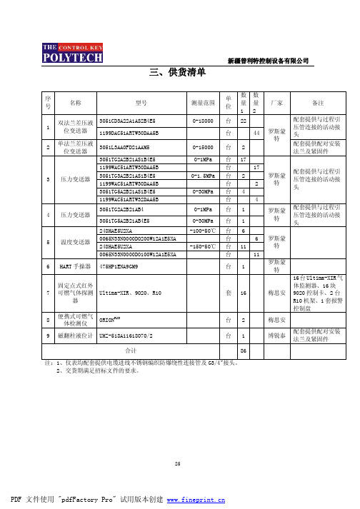
0-18000 0-15000
台 22
配套提供与过程引
台
44
罗斯蒙
压管连接的活动接 头
特
台2
配套提供配对安装 法兰及紧固件
0-1MPa 台 17
0-1.5MPa
台 台 台
2
17 2
罗斯蒙 特
配套提供与过程引 压管连接的活动接 头
0-30MPa 台 4
台
4
0-1MPa 0-30MPa
台1 台1
罗斯蒙 特
三、供货清单
新疆普利特控制设备有限公司
序 号
名称
型号
1
双法兰差压液 3051CD3A22A1AS2B4E5 位变送器 1199DAC51ARTW30DAA5B
2
单法兰差压液 位变送器
艾默生 罗斯蒙特 (Rosemount) 3418 数据表

产品样本00813-0106-3418, Rev AB2022 年 8 月罗斯蒙特 (Rosemount™) 3418八声道气体超声波流量计3418 型气体超声波流量计面向贸易交接的高精度罗斯蒙特 3418 是一款 8 声道气体超声波流量计,设计用于天然气贸易交接应用,在这些应用中,由于传输体积量大,且安装设施紧凑,因此高精度和长期可靠的性能是关键。
这款 8 声道弦向流量计的 8 个声道位于四个彼此相对的位置上,让流量计能够消除不对称流速效应。
这款流量计具有更高的流量分辨率,且能够更准确地计算涡流;因此,对于因管道弯曲、直管段较短或者设计占地空间较小所致的不理想的流场畸变,它能够轻松地进行补偿。
这就降低了对流量调节元件的需求,以及对在上游配置长管段的需求,从而能够尽可能减少空间占用,节省安装成本。
罗斯蒙特 3418 通过十六 (16) 个传感器模块形成八 (8) 个弦向声道,它配有一个变送器,能够对来自这八个弦向声道的流速测量值求取平均值,从而计算总流量。
变送器执行所有控制和定时功能,以便生成和测量声脉冲。
声学处理由专门的自研 3410 电子元件执行,这些电子元件能够实现高采样率,并提供稳定的超声波信号和理想的小流量响应。
罗斯蒙特 3418 有 DN250 至 DN1050(10 英寸至 42 英寸)口径可供选择,它支持双向流测量,拥有更大的流量测量容量,且不存在逐渐增大的压降,因此能降低测量风险,尽可能降低运营成本。
罗斯蒙特 3418 气体超声波流量计设计用于减小因安装影响所致的偏移,从而降低不确定性。
它的 OIML 准确度等级为 0.5 级,只需要配置长度相当于五倍管径的直管段,不需要流量调节装置。
为进一步提高测量可靠性,流量计经过特殊配置,能够实时处理声速计算,且可使用 AGA 10 或 GERG 2008 方法将理论值与实际值进行比较。
流量计将藉由直接输入来使用实时气体成分数据以及压力和温度数据。
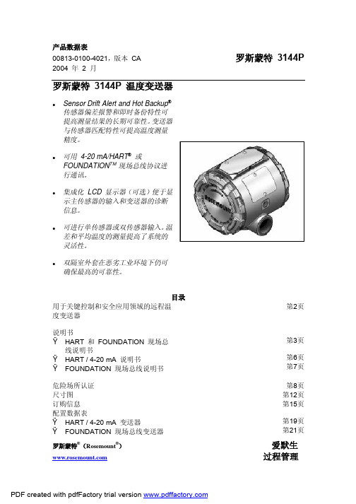
罗斯蒙特3144P温度变送器

罗斯蒙特3144P温度变送器业界领先的过程测量解决方案,提供无与伦比的现场可靠性和创新性•超高精度和稳定性•支持多种输入(热电阻、热电偶、毫伏、欧姆),支持双传感器和单传感器输入•全面的传感器和过程诊断功能•IEC 61508 安全认证•双室外壳•大LCD 显示屏•HART 修订版(版本5 和版本7 )或FOUNDA TION 现场总线协议可供选择变送器的特性有:•支持双传感器和单传感器输入•变送器- 传感器匹配(选项代码C2 )•一体化防雷端子( 选项代码T1)•通过IEC 61508 安全认证( 选项代码QT)•高级传感器和过程诊断功能( 选项代码D01 和DA1)•易读的大LCD 显示屏( 选项代码M5)•" 组装到传感器" 选项( 选项代码XA)罗斯蒙特3144P 温度变送器订购信息型号产品描述3144P 温度变送器外壳型式材料导线管入口尺寸D1 现场安装外壳,双室外壳铝1/2-14 NPTD2 现场安装外壳,双室外壳铝M20 x 1.5 (CM20)D3 现场安装外壳,双室外壳铝PG 13.5 (PG11)D4 现场安装外壳,双室外壳铝JIS G /2D5 现场安装外壳,双室外壳不锈钢1/2-14 NPTD6 现场安装外壳,双室外壳不锈钢M20 x 1.5 (CM20)D7 现场安装外壳,双室外壳不锈钢PG 13.5 (PG11)D8 现场安装外壳,双室外壳不锈钢JIS G /2变送器输出A 4–20 mA ,采用基于HART 协议的数字信号F FOUNDATION 现场总线数字信号( 包括 3 个模拟输入功能块和备用链路活动调度器)测量配置1 单传感器输入2 双传感器输入产品认证NA 无认证E5 FM 隔爆、防尘燃和非易燃认证I5(1) FM 本安和非易燃( 对于现场总线设备,包括标准IS 和FISCO)K5(1) FM 本安、非易燃和隔爆组合( 对于现场总线设备,包括标准IS 和FISCO)KB(1) FM 和CSA 本安、隔爆和非易燃组合( 对于基金会现场总线设备,包括标准IS 和FISCO)I6(1) CSA 本安/FISCO Division 2 ( 对于现场总线设备,包括标准IS 和FISCO)K6(1) CSA 本安、FISCO Division 2 和隔爆组合( 对于现场总线设备,包括标准IS 和FISCO)E1 ATEX 隔爆认证N1 ATEX n 型认证I1(1) ATEX 本安认证( 对于现场总线设备,包括标准IS 和FISCO)K1(1) ATEX 本安、隔爆、防尘燃和n 型组合( 对于现场总线设备,包括标准IS 和FISCO)ND ATEX 防尘燃认证KA(1) ATEX/CSA 本安、隔爆组合( 对于现场总线设备,包括标准IS 和FISCO) E7 IECEx 隔爆认证N7 IECEx "n" 型认证组装到选项XA 传感器单独指定,并组装到变送器上典型型号: 3144P D1 A 1 E5 B4 M5(1) 当针对FOUNDATION 现场总线要求本安认证时,标准本安和FISCO 本安认证同时适用。
罗斯蒙特3144温度变送器说明书

(1) !"#$%&'&(!")*+ !"#$%&'()*+,-./01234"#56 (2) ! !"# 375 !"#$%& (3) !"#$% !&$ / !"#$% (4) ! HART/4-20 mA (5) !"#$%&' !"#$ 0.25 C 0.45 F !"#$ (6) NIST B !" 100 300 C 212 572 F !"# 3.0 C 5.4 F (7) NIST K !" -180 -90 C -292 -130 F !" 0.50 C 0.9 F)
3144P
!"#$%&'()* !"#$%&" !"#$%&'($)*+ !"#$%&'( !"#$%&'()*+,!" G1 !"#$%&' !"#$%&'()* ASME B 16.5 ANSI /IEEE C62.41-1991 IEEE 587 / ! A2 B3 6kV/3kA 6kV/0.5kA 4kV 1.2x50 S 100 kHz 8x 20 ! S ! 2
2
B
E J K N R T DIN L DIN U W5Re/W26Re ! 2,3,4
(1) (2)
S
!"
0.014 0.029 - R - 300 0.0021% 0.046 - R - 100 0.0086% 0.004 + R 0.00043% 0.004 + R 0.00029% 0.004 + R 0.0020% 0.005 + R 0.00054% 0.005 + R 0.0020% 0.005 + R 0.00036% 0.015 0.021 - R 0.0032% 0.005 0.005 + R 0.00036% 0.0054 + R 0.00029% 0.0054 + R 0.0025% 0.0064 0.0064 + R 0.0043% 0.016 0.023 + R 0.0036% 0.00025 mV 0.007
0065(0185)温度传感器选型样本
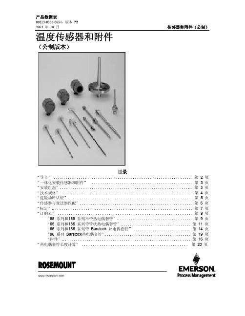
传感器和附件(公制)
2
概述
产品数据表
00813-0200-2654,版本 FB 2003 年 10 月
导言
选择延伸件和热电偶套管
罗斯蒙特集成化安装温度传感器,附件硬件及装 配件组成了一整套的工业温度传感仪表。多种电 阻式温度检测器和热电偶传感器可单独使用或作 为完整装配件使用,完整装配件包括接线盒、热 电偶套管和延伸附件。这里所提供的产品是为完 整装配件的应用而设计的,包括罗斯蒙特智能和 可编程温度变送器。请向当地罗斯蒙特代表索取 详细资料。
铠装材料 罗斯蒙特热电偶由矿物绝缘电缆组成,设计采用多种铠装材 料用以适应温度及环境。对于空气中温度达到 800 °C 的情 况,采用 AISI 321标准。对于空气中温度达到 800 至 1100 °C的情况,采用 英科耐尔 600 标准。对于空气中温度高于 1100 °C 的情况,根据要求,可采用贵金属或陶瓷铠装。对 于强氧化或还原的环境,请向当地罗斯蒙特代表咨询。
表 1 185 系列热电偶特征
类型 J K N
合金(导线颜色) Fe(+黑),CuNi(-白) NiCr(+绿),NiAl(-白) NiCrSi(+红),NiSi(-白)
铠装材料 1.4541(AISI 321) 英科耐尔 600
Nicrobell B
温度范围(°C) - 40 至 375,375 至 750 - 40 至 375,375 至 1000 - 40 至 375,375 至 1000
如图 1 所示,90 mm 的“N”尺寸将导致外壳 温度升高 22 °C。因此,100 mm“N”尺寸为 最小推荐长度并将提供大约 25 °C 的安全系数。 将需要一个更长的“N”尺寸(如 150 mm), 以降低由变送器温度影响引起的误差,尽管在这 种情况下,变送器可能需要额外支架。
罗斯蒙特阀组选型资料和尺寸图

Product Data SheetMarch 201700813-0100-4733, Rev PF⏹Factory assembled, leak-tested, and calibrate⏹Full breadth of offering including integral, in-line, and conventional ⏹Integral design enables “flangeless” connection to instrument ⏹Block and bleed, 2-, 3-, and 5-valve configurations ⏹Compact, lightweight design ⏹Easy in-process calibration ⏹Direct-mount capability⏹Available in NACE ®-compliant materials of constructionRosemount ™ ManifoldsRosemount Manifolds March 2017 Selection guideRosemount 305 Integral ManifoldSee “Rosemount mounting brackets” on page28.⏹Assembles directly to transmitter, eliminating need for flange⏹2-, 3-, and 5-valve configuration⏹Available with vertical or horizontal process connections⏹Compact, lightweight assembly⏹Factory assembled, seal-tested, and calibrated⏹50 percent fewer leak points than conventional transmitter toflange to manifold interface⏹Female NPT process connectionsRosemount 306 In-line ManifoldSee “Rosemount mounting brackets” on page28.⏹Assembled directly to in-line pressure transmitters orRosemount Wireless Pressure Gauge⏹Block-and-bleed and 2-valve configurations⏹Male or female threaded NPT process connectionRosemount 306 In-Line ManifoldRosemount 304 ConventionalManifoldSee “Rosemount mounting brackets” on page28.⏹Attaches to transmitter flange⏹2-, 3-, and 5-valve configurations⏹Traditional (Flange ϫ Flange, Flange ϫ NPT) and wafer styles⏹Factory assembled, seal-tested, and calibratedRosemount 304 Conventional Manifold - Traditional StyleRosemount 304 Conventional Manifold - Wafer StyleContentsValve configuration . . . . . . . . . . . . . . . . . . . . . . . . . . . . . . . 3Ordering information . . . . . . . . . . . . . . . . . . . . . . . . . . . . . 4Specifications . . . . . . . . . . . . . . . . . . . . . . . . . . . . . . . . . . .13Dimensional drawings . . . . . . . . . . . . . . . . . . . . . . . . . . . .19 Rosemount 305 Integral Manifold -Coplanar StyleRosemount 305 Integral Manifold -Traditional StyleRosemount ManifoldsMarch 2017Valve configurationBlock-and-bleedThe block-and-bleed configuration is available on theRosemount 306 Manifold for use with in-line gage and absolute pressure transmitters. A single isolate valve provides instrument isolation and a bleed screw provides drain/vent capabilities.Rosemount 306 ManifoldTwo-valveThe 2-valve configuration is available on Rosemount 305, 306, and 304 Manifolds for use with absolute and gage pressure transmitters. An isolate valve provides instrument isolation and a drain/vent valve allows venting, draining, or calibration.Rosemount 305 and 306 ManifoldsRosemount 304 ManifoldThree-valveThe 3-valve configuration is available on Rosemount 305 and 304 Manifolds for use with differential pressure and multi-variable transmitters. Two isolate valves provide instrument isolation, and one equalize valve is positioned between the high and low process connections.Rosemount 305 ManifoldRosemount 304 (Traditional) ManifoldRosemount 304 (Wafer) ManifoldNoteVent ports receive plastic caps to protect threaded connections unless otherwise noted.NotePlugged connections receive 1/4-in. NPT plugs unless otherwisenoted.Rosemount Manifolds March 2017Five-valveThe 5-valve configuration is available on Rosemount 305 and 304 Manifolds for use with differential pressure and multivariable transmitters. Two isolate valves provide instrument isolation and one equalize valve is positioned between the high and low process connections. In addition, two drain/vent valves allow for controlled venting, 100 percent capture of vented or drained process, and simplified in-process calibration capability.Rosemount 305 Manifolds and 304 (Wafer)Five-valve natural gasThe 5-valve natural gas configuration is available on the Rosemount 305 and 304 Manifolds for use with differential pressure and multivariable transmitters. Two isolate valves provide instrument isolation and a single drain/vent valve allows for controlled venting, 100 percent capture of vented or drained process, and simplified in-process calibration capability. In addition, two equalize valves provide extra protection from leaking to ensure DP signal integrity.⏹“NG” option includes wide handle pattern and soft seats for ease of use as well as a larger bore to reduce plugging Rosemount 305 Manifolds and 304 (Traditional)NoteVent ports receive plastic caps to protect threaded connections unless otherwise noted.NotePlugged connections receive 1/4-in. NPT plugs unless otherwise noted.Ordering information Rosemount Manifolds can be ordered as a stand-alone product or as an integrated assembly attached to a transmitter.Stand-alone manifold1.Reference the “Selection guide” on page2 for assistanceon choosing the type of manifold.2.Specify a completed model number by referencing theapplicable ordering table for the selected manifold type:⏹Rosemount 305 Integral Manifold, see page5.⏹Rosemount 306 In-line Manifold, see page8.⏹Rosemount 304 Conventional Manifold, see page10.Transmitter/manifold assembly1.Specify a completed Rosemount transmitter modelnumber by referencing the applicable product data sheet.2.Specify a completed manifold model number byreferencing the applicable ordering table for the selectedmanifold type:⏹Rosemount 305 Integral Manifold, see page5.⏹Rosemount 306 In-line Manifold, see page8⏹Rosemount 304 Conventional Manifold, see page10.3.Verify the transmitter model number contains the correct“Process Connection” code or “Manifold Option” code for the desired transmitter manifold assembly (see Table 1).Table 1. Ordering Codes for a Transmitter/ManifoldAssemblyTransmitter ManifoldProcessconnection code“Manifold”option codeRosemount3051S305A11N/A306A11N/A304A12N/ARosemount3051/2051305N/A S5306N/A S5304N/A S6Rosemount2088305N/A N/A306N/A S5304N/A N/AAlisa Peng whdkmsale@ wechat:whdkmsaleRosemount Manifolds March 2017Specification and selection of product materials, options, or components must be made by the purchaser of the equipment. See page13 for more information on material selection.Table 2. Rosemount 305 Integral Manifold Ordering InformationThe starred offerings (★) represent the most common options and should be selected for best delivery. The non-starred offerings are subject to additional delivery lead time.Model Product description0305Integral manifoldManufacturerR Rosemount★Manifold styleC Coplanar★T Traditional★M Traditional (DIN-compliant flange)★Manifold type22-valve★33-valve★5(1)5-valve★6(2)5-valve natural gas metering pattern★7(2)(3)2-valve (per ASME B31.1 [ANSI] power and piping code)8(2)(3)3-valve (per ASME B31.1 [ANSI] power and piping code)9(2)(3)5-valve (per ASME B31.1 [ANSI] power and piping code)Body(4)Bonnet Stem and tip/ball2316 SST/316L SST316 SST316 SST★3(5)Alloy C-276Alloy C-276Alloy C-2764(5)(6)Alloy 400Alloy 400Alloy 400Process connection styleA(7)1/4–18 NPT female ★B(8)1/2–14 NPT female★Packing material1(9)PTFE★2(10)Graphite-basedValve seat1 Integral★5Soft POM (only available with natural gas metering pattern)★OptionsExtended product warrantyWR33-year limited warranty★WR55-year limited warranty★Rosemount Manifolds March 2017Table 2. Rosemount 305 Integral Manifold Ordering InformationThe starred offerings (★) represent the most common options and should be selected for best delivery. The non-starred offerings are subject to additional delivery lead time.Mounting bracketsB1Bracket for 2-in. pipe mounting, CS bolts★B3(11)Flat bracket for 2-in. pipe mounting, CS bolts★B4SST mounting bracket for 2-in. pipe mounting, 300 SST bolts★B7B1 bracket with 316 SST bolts★B9(11)B3 bracket with 316 SST bolts★BA316 SST B1 bracket with 316 SST bolts★BC(11)316 SST B3 bracket with 316 SST bolts★BE316 SST B4 bracket with 316 SST bolts★BF CS panel mount bracket★BG300 SST panel mount bracket★Bolt materialsL4(12)Austenitic 316 SST bolts★L5ASTM A193, Grade B7M bolts★L8ASTM A193, Class 2, Grade B8M bolts★Cleaning(13)P2Cleaning for special services★Material recommendations for NACE(5)(14)SG Sour gas (meets NACE MR0175/ISO 15156, MR0103/ISO 17495)★Adapters(15)DF1/2–14 NPT female flange adapter★DQ12 mm ferrule tube flange adapterProcess flowmeter configurationPF Relocated equalize valve for 9295 Process FlowmeterProcess flange bolting connection(16)HK10 mm (M10) process flange bolting connection★HL12 mm (M12) process flange bolting connection★Typical coplanar integral manifold model number: 305 R C 3 2 B 1 1 B41.Not available with traditional manifold style T.2.Only available with coplanar manifold style code C.3.Only available with 316 SST materials of construction code 2 and graphite-based packing code 2.4.Refer to Table 13 on page18 for additional detail on process wetted materials of construction.5.Materials of construction comply with recommendations per NACE MR0175/ISO 15156 for sour oil field production environments. Environmental limits apply tocertain materials. Consult latest standard for details. Selected materials also conform to NACE MR0103/ISO 17495 for sour refining environments.6.Includes Alloy C - 276 drain vents.7.Only available with traditional manifold style codes T and M.8.Not available with traditional manifold style code M. Manifold style code T does not include mounting holes on process flange.9.Includes PTFE tape on drain/vent valves and plugs.Rosemount Manifolds March 201710.Includes graphite tape on drain/vent valves and plugs.11.Not compatible with the Rosemount 3095 Transmitter.12.Not available with ASME B31.1 manifold type codes 7, 8, and 9.13.Not available with graphite-based packing material code 2.14.Only allowed with material of construction code 2.15.Only allowed with traditional manifold style codes T and M. Not allowed with graphite-based packing code 2.16.Only available with traditional manifold style code M.Rosemount Manifolds March 2017 Specification and selection of product materials, options, or components must be made by the purchaser of the equipment. Seepage13 for more information on material selection.Table 3. Rosemount 306 Pressure Manifold Ordering InformationThe starred offerings (★) represent the most common options and should be selected for best delivery. The non-starred offerings are subject to additional delivery lead time.Model Product description0306Pressure manifoldManufacturerR Rosemount★Manifold styleT Threaded★Manifold type1Block-and-bleed★22-valve★3(1)2-valve (per ASME B31.1 power piping code)Body(2)Bonnet Stem and tip/ball2316 SST/316L SST316 SST316 SST★3(3)(4)Alloy C-276Alloy C-276Alloy C-276Process connectionAA1/2–14 male NPT process connection for in-line transmitter ★AW1/2–14 male NPT process connection for Rosemount Wireless Pressure Gauge★BA(3)1/2–14 female NPT process connection for in-line transmitter★BW1/2–14 female NPT process connection for Rosemount Wireless Pressure Gauge★Packing material1(5)PTFE★2(6)Graphite-basedValve seat1Integral★OptionsExtended product warrantyWR33-year limited warranty★WR55-year limited warranty★Cleaning(7)P2Cleaning for special servicesRosemount ManifoldsMarch 2017Material recommendations for NACE (4)(8)SGSour gas (meets NACE MR0175/ISO 15156, MR0103/ISO 17495)★Typical integral manifold model number: 306 R T 2 2 BA 1 11.Only available with 316 SST materials of construction and graphite-based packing.2.Refer to Table 14 on page 18 for additional detail on process wetted materials of construction.3.Not available with block-and-bleed manifold type.4.Materials of Construction comply with recommendations per NACE MR0175/ISO 15156 for sour oil field production environments. Environmental limits apply to certain materials. Consult latest standard for details. Selected materials also conform to NACE MR0103/ISO 17495 for sour refining environments.5.Includes PTFE tape on drain/vent valves and plugs.6.Includes graphite tape on plugs.7.Not available with graphite-based packing material code 2.8.Only allowed with material of construction code 2.Table 3. Rosemount 306 Pressure Manifold Ordering InformationThe starred offerings (★) represent the most common options and should be selected for best delivery. The non-starred offerings are subject to additional delivery lead time.Rosemount Manifolds March 2017 Specification and selection of product materials, options, or components must be made by the purchaser of the equipment.See page13 for more information on material selection.Table 4. Rosemount 304 Conventional Manifold Ordering InformationThe starred offerings (★) represent the most common options and should be selected for best delivery. The non-starred offerings are subject to additional delivery lead time.Model Product description0304Conventional manifoldManufacturerR Rosemount★Manifold styleT Traditional (flange ϫ flange or flange ϫ NPT)★W(1)WaferManifold type2(2)2-valve★33-valve★5(3)5-valve★6(2)5-valve natural gas metering pattern★7(2)(4)2-valve (per ASME B31.1 [ANSI] power and piping code)8(2)(4)3-valve (per ASME B31.1 [ANSI] power and piping code)Body(5)Bonnet Stem Tip2316 SST/316L SST316 SST316 SST316 SST★5CS316 SST316 SST316 SST★Process connection styleB1/2–14 NPT★F(2)Flanged★Packing/stem seal material1(6)PTFE★2(1)(7)Graphite-based3(8)FKM Elastomer O-ring★Bolts1For assembly to Rosemount 2051/3051 Traditional Flange★2For assembly to Rosemount 2051/3051 DIN-compliant Traditional Flange★3For assembly to Rosemount2051/3051 Coplanar™ Flange★Table 4. Rosemount 304 Conventional Manifold Ordering InformationThe starred offerings (★) represent the most common options and should be selected for best delivery. The non-starred offerings are subject to additional delivery lead time.OptionsGas-metering configurationNG(9)Wide handle pattern, 3/8-in. bore, soft POM seat★Extended product warrantyWR33-year limited warranty★WR55-year limited warranty★Mounting bracketsVC(2)Manifold heavy duty mounting bracket, CS for traditional style★VS(2)Manifold heavy duty mounting bracket, 316 SST for traditional style★B4(3)Manifold SST mounting bracket for 2-in. pipe mount with series 300 SST bolts for wafer style★Adapters and connectors(10)DF1/2–14 NPT female flange adapter★DT1/2-in. ferrule tube flange adapter★DQ12mm ferrule tube flange adapter★DV(11)1/2–14 NPT male non-stabilized connectors★DH(11)1/2–14 NPT male stabilized extended connectors★Dielectric isolator kitsG2(12)Dielectric isolators and bolt sleeves for connectors★Bolt materialL4(13)Austenitic 316 SST bolts★L5ASTM A193, Grade B7M bolts★L8ASTM A193, Class 2, Grade B8M bolts★Material recommendations for NACE(1)(14)SG Sour gas (meets NACE MR0175/ISO 15156, MR0103/ISO 17954)★Cleaning(15)P2Cleaning for special serviceHeater block kits(16)SB Steam block kit, 1/4-in. NPT connection★Typical model number: 0304 R T 3 2 B 1 1 VS1.Only allowed with material of construction code2.2.Not available with wafer manifold style code W.3.Not available with traditional manifold style code T.4.Only available with 316 SST materials of construction code 2 and graphite-based packing code 2.5.Refer to Table 15 on page18 for additional detail on process wetted materials of construction.6.Includes PTFE tape on drain/vent valves and plugs.7.Includes graphite tape on plugs.8.Only available with option code NG.9.Only available with manifold type code 6.10.Only allowed with both manifold style code T and process connection code F. Not allowed with Graphite-based packing code 2.11.Only available with manifold style code 6.12.Only available with option codes DV and DH.13.Not available with manifold type codes 7, 8.14.Materials of construction comply with recommendations per NACE MR0175/ISO 1516 for sour oil field production environments. Environmental limits apply tocertain materials. Consult latest standard for details. Selected materials also conform to NACE MR0103/ISO 17495 for sour refining environments.15.Not available with Graphite-based packing material code 2.16.Not available with manifold type code 6.SpecificationsMaterial selectionEmerson ™ provides a variety of Rosemount product with various product options and configurations including materials ofconstruction that can be expected to perform well in a wide range of applications. The Rosemount product information presented is intended as a guide for the purchaser to make an appropriate selection for the application. It is the purchaser’s sole responsibility to make a careful analysis of all process parameters (e.g. all chemical components, temperature, pressure, flow rate, abrasives, contaminants), when specifying product, materials, options and components for the particular application. Emerson is not in a position to evaluate or guarantee the compatibility of the process fluid or other process parameters with the product, options, configuration or materials of construction selected. For more information on material compatibility, refer to the Material Selection Technical Note.Pressure and temperature ratingsFigure 1. Rosemount 305 Integral ManifoldsTable 5. Rosemount 305 Integral Manifolds (1)1.Except option HK:PTFE, integral seat: 2324 psi @ 200 °F (160 bar @ 93 °C), 1680 psi @ 400 °F (116 bar @ 204 °C)Graphite, integral seat: 2324 psi @ 200 °F (160 bar @ 93 °C), 1125 psi @ 750 °F (78 bar @ 399 °C)PackingSeatPressure and temperature ratingsPTFE Integral 6092 psi @ 200 °F (420 bar @ 93 °C)4000 psi @ 400 °F (276 bar @ 204 °C)PTFE Soft POM 6092 psi @ 200 °F (420 bar @ 93 °C)GraphiteIntegral 6092 psi @ 200 °F (420 bar @ 93 °C)1500 psi @ 750 °F (103 bar @ 399 °C)Graphite (ASME B31.1)Integral6092 psi @ 100 °F (420 bar @ 38 °C)3030 psi @ 1000 °F (201 bar @ 538 °C)Figure 2. Rosemount 306 In-line ManifoldsTable 6. Rosemount 306 In-line ManifoldsPackingSeatPressure and temperature ratingsPTFE Integral 10000 psi @ 85 °F (689 bar @ 29 °C)4000 psi @ 400 °F (276 bar @ 204 °C)GraphiteIntegral 6000 psi @ 200 °F (414 bar @ 93 °C)1500 psi @ 750 °F (103 bar @ 399 °C)Graphite (ASME B31.1)Integral6000 psi @ 100 °F (414 bar @ 38 °C)3030 psi @ 1000 °F (201 bar @ 538 °C)Figure 3. Rosemount 304 Conventional ManifoldsTable 7. Rosemount 304 Conventional ManifoldsPackingSeatPressure and temperature ratingsPTFE (1)1.Maximum working pressure limited to 4500 psi (310 bar) with G2 option.Integral 6000 psi @ 200 °F (414 bar @ 93 °C)4000 psi @ 400 °F (276 bar @ 204 °C)Graphite - wafer Integral 6000 psi @ 200 °F (414 bar @ 93 °C)1500 psi @ 750 °F (103 bar @ 399 °C)Graphite - flanged (SST)Integral 6000 psi @ 200 °F (414 bar @ 93 °C)1500 psi @ 1000 °F (103 bar @ 538 °C)Graphite - flanged (CS)Integral 6000 psi @ 200 °F (414 bar @ 93 °C)1500 psi @ 800 °F (103 bar @ 427 °C)Graphite (ASME B31.1)Integral 6000 psi @ 100 °F (414 bar @ 38 °C)3030 psi @ 1000 °F (201 bar @ 538 °C)PTFE POM 4500 psi @ 212F (310 bar @ 100 C)FKM O-ringPOM4500 psi @ 212 F (310 bar @ 100 C)Instrument connectionsO-ringsFigure 5. Rosemount 304 Conventional ManifoldTable 8. Manifold - Transmitter InterfaceModelConnectionRosemount 305 Integral Manifold Mounted directly to coplanar sensor module of transmitter, 1.3-in. (287 mm) center-to-center process isolatorsRosemount 306 In-line Manifold 1/2–14 male NPT for In-line transmitters 1/2-14 female NPT for Rosemount Wireless Pressure GaugeRosemount 304 Conventional ManifoldMounted to traditional transmitter flange, 21/8-in. (54 mm) center-to-center connection per IEC 61518, Type B shut-off device (without spigot)1.Available in packing material code 1 (PTFE) or code 2 (Graphite).Process connectionsVent port connections1/4–18 female NPTManifold boltsStandard material is plated Carbon Steel per ASTM A449, Type 1Alternative bolt materials offered through option codes:⏹L4 for Austenitic 316 stainless steel bolts ⏹L5 for ASTM A193, Grade B7M Bolts ⏹L8 for ASTM A193, Grade B8M Class 2 boltsTable 9. Rosemount 305 Integral ManifoldStyleConnectionCoplanar 1/2–14 female NPTTraditional1/4–18 female NPT(process adapters optional)Table 10. Rosemount 306 In-line ManifoldStyleConnectionBlock-and-bleed 1/2–14 male NPT(1)1.1/2-14 female NPT option only available with Wireless Pressure Gauge.2-valve1/2–14 NPT (male or female)Table 11. Rosemount 304 Conventional ManifoldStyleConnectionFlange by pipe 1/2–14 female NPTFlange by flange 21/8-in. (54 mm) center-to-centerconnection (process adapters required)Wafer1/2-14 female NPTTable 12. Adapters and ConnectorsOption DescriptionImageDF1/2-14 NPT female flange adapter•Available with Rosemount 305Integral and 304 Conventional ManifoldsDT1/2-in. ferrule tube flange adapter•Available with Rosemount 304 Conventional ManifoldDQ12mm ferrule tube flange adapter•Available with Rosemount 305 Integral and 304 Conventional ManifoldsDV (1)Non-stabilized connector•3.00-in.•No stabilizing foot•Includes assembly hardwareDH (1)Stabilized extended connectors•4.75-in.•Stabilizing foot•Includes assembly hardwareG2(1)(2)Dielectric isolators•Rated to 2500 VDC and 5 mega-Ohms•Includes bolts sleeves and assembly hardware1.Only allowed with both Rosemount 304 Manifold type code 6 and process connection code F. Not allowed with Graphite- based packing code2.2.Maximum working pressure of assembly limited to 4500 psi (310 bar), 3626 psi (250 bar) at –20 °F (–29 °C), and 3626 psi (250 bar) at 150 °F (66 °C).Table 12. Adapters and ConnectorsOption DescriptionImageMaterials of construction Process wetted TypicalFigure 6. Typical Rosemount Manifold Valve Estimated weightTable 13. Rosemount 305 Integral ManifoldComponent Option 2Option 2with SGOption 3Option 4Body 316 SST/316L SST316 SST/316L SSTAlloy C-276Alloy 400Ball/tip 316 SST/316Ti SSTAlloyC-276Alloy C-276Alloy 400Stem316 SST AlloyC-276Alloy C-276Alloy 400Packing PTFE/GraphitePTFE/GraphitePTFE/GraphitePTFE/GraphiteBonnet316 SST316 SST Alloy C-276Alloy 400 Pipe plug316 SST316 SST Alloy C-276Alloy 400Drain/vent valve 316 SSTAlloyC-276Alloy C-276Alloy 400Table 14. Rosemount 306 In-line ManifoldComponent Option 2Option 2with SGOption 3Body 316 SST/316L SST316 SST/316L SSTAlloy C-276Ball/tip 316 SST/316Ti SSTAlloy C-276Alloy C-276Stem316 SST Alloy C-276Alloy C-276 Packing PTFE/Graphite PTFE/Graphite PTFE/Graphite Bonnet316 SST316 SST Alloy C-276 Pipe plug316 SST316 SST Alloy C-276Bleed screw 316 SST/316Ti SSTAlloy C-276Alloy C-276Table 15. Rosemount 304 Conventional ManifoldComponent Option 2Option 2with SGOption 5Body 316 SST/316L SST316 SST/316L SSTCSBall/tip 316 SST/316Ti SSTAlloy C-276316 SSTStem316 SST Alloy C-276316 SSTPacking PTFE/GraphitePTFE/GraphitePTFEBonnet316 SST316 SST CS Pipe plug316 SST316 SST CS A. BonnetB. StemC. PackingD. Ball/tipE. BodyTable 16. Rosemount 305 Integral Manifold Description Weight2-valve coplanar 4.5 lbs (2.0 kg) 2-valve traditional 6.0 lbs (2.7 kg) 3-valve coplanar 4.7 lbs (2.1 kg) 3-valve traditional 6.0 lbs (2.7 kg) 5-valve coplanar 6.5 lbs (3.0 kg) Table 17. Rosemount 306 In-line Manifold Description Weight Block-and-bleed 1.1 lbs (0.5 kg) 2-valve 2.5 lbs (1.1 kg) Table 18. Rosemount 304 Conventional Manifold Description Weight2-valve traditional flange ϫ NPT 5.0 lbs (2.3 kg) 2-valve traditional flange ϫ flange 5.5 lbs (2.5 kg) 3-valve traditional flange ϫ NPT 5.2 lbs (2.4 kg) 3-valve traditional flange ϫ flange 5.7 lbs (2.6 kg) 3-valve wafer flange ϫ NPT 4.0 lbs (1.8 kg) 5-valve wafer flange ϫ NPT 5.7 lbs (2.6 kg) 5-valve traditional flange ϫ NPT 5.7 lbs (2.6 kg) 5-valve traditional flange ϫ flange 5.7 lbs (2.6 kg)Dimensional drawingsRosemount 305 Manifold(1)Figure 7. Rosemount 305RC 2-Valve Coplanar Style ManifoldA. 1/2–14 NPT on manifold for process connection, 1/4–18 NPT for test/vent connectionDimensions are in inches (millimeters).Figure 8. Rosemount 305RC 3-Valve Coplanar Style ManifoldsA. Drain/vent valveB. 1/2–14 NPT on manifold for process connections, 21/8-in. center-to-centerDimensions are in inches (millimeters).1.Manifold handle assembly may vary slightly from image shown. All valve handle assemblies provide the same function and meet all stated drawing dimensions.Figure 9. Rosemount 305RC 5-Valve Coplanar Style ManifoldA. 1/2–14 NPT on manifold for process connections, 21/8-in. center-to-center, 1/4–18 NPT for test/vent connection Dimensions are in inches (millimeters).Figure 10. Rosemount 305RT 2-Valve Traditional Style ManifoldA./2–14 NPT on optional process adapterB. 1/4–18 NPT on traditional manifold for process connection without the use of a process adapter Dimensions are in inches (millimeters).Figure 11. Rosemount 305RT 3-Valve Traditional Style ManifoldFigure 12. Rosemount 305RM 2-Valve Traditional DIN Style ManifoldA. Drain/vent valveB. 1/2–14 NPT on optional process adapter (1)1.Adapters can be rotated to give adapter connection centers of 2.0 (51), 2.125 (54), or 2.25 (57).C. 1/4–18 NPT on traditional manifold for process connections without the use of process adaptersDimensions are in inches (millimeters).A. 1/2–14 NPT on optional process adapterC. 1/4–18 NPT vent connection B. 1/4–18 NPT on traditional manifold for process connection without the use of a process adapter Dimensions are in inches (millimeters).Figure 13. Rosemount 305RM 3-Valve Traditional DIN Style ManifoldFigure 14. Rosemount 305RM 5-Valve Traditional DIN Style ManifoldB. 1/2–14 NPT on optional process adapter (1)1.Adapters can be rotated to give adapter connection centers of 2.0 (51), 2.125 (54), or 2.25 (57).4D. 0.75 (19) clearance for cover removalDimensions are in inches (millimeters).A. 1/2–14 NPT on optional process adapter (1)B. 1/4–18 NPT on traditional manifold for process connections without the use of process adapters Dimensions are in inches (millimeters).1.Adapters can be rotated to give adapter connection centers of 2.0 (51), 2.125 (54), or 2.25 (57).Rosemount 306 Manifold (1)Figure 15. Rosemount 306RT Pressure Style Manifold (3051S_T Shown)(2)Rosemount 304 Manifold (1)Figure 16. Rosemount 304RT 2-Valve Flange ϫ NPT Conventional Manifold1.Manifold handle assembly may vary slightly from image shown. All valve handle assemblies provide the same function and meet all stated drawing dimensions.Block-and-bleed style2-valve styleA. Bleed screw (unspecified dimension) - not designed for accessory attachments. C. 1/2–14 NPT female NPT process connection (code BA)B. 1/4-in. vent connection–pipe plug supplied with manifold, but not installed at factory (pipe plug supplied loose)Dimensions are in inches (millimeters).2.Manifold valve orientation may vary with respect to transmitter mounting holes.Instrument sideProcess sideA. 0.281 mounting holes (2)B. 1/4-in. NPT test (plugged)C. 1/2-in. NPT process connection on 2.125 (54) centers (2)Dimensions are in inches (millimeters).∅。
罗斯蒙特 3144P 智能温度变送器

智能温度变送器1前言目前选用的罗斯蒙特温度变送器主要是3144P型和848T型变送器,FF总线仪表。
2 特点采用 HART 协议的罗斯蒙特 3144P 温度变送器具有卓越的测量精度、稳定性和可靠性,使其成为控制/安全应用中的行业领先温度变送器。
罗斯蒙特 3144P 具有支持单传感器输入和双传感器输入的双重能力。
双传感器输入能力使变送器能够同时从两个独立的传感器接收输入信号。
双传感器组态能够用于测量温差、温度平均或用于冗余温度测量。
•用于控制/安全领域的最佳温度变送器•一个变送器同时具有支持单传感器和双传感器的能力•增强的抗 EMI 和滤波能力在过程测量中确保了卓越的稳定性•通过 IEC61508 安全仪表系统(SIS)的第三方计量认证•行业领先的 5 年稳定性,降低维护成本•热备份® 和传感器漂移警告特性可提高测量的长期可靠性•变送器与传感器匹配消除了传感器的互换性误差,将测量精度提高 75%•即使在苛刻环境下,双室外壳也可确保最高的可靠性•一体化 LCD 表头的宽大显示屏,方便读数3 技术说明3.1 仪表整体防爆及防护等级:防爆等级:dIIBT4 、dIIBT5 ;防护等级:IP54。
3.2 仪表输出:模拟量输出::4-20mA HART通讯协议;总线输出:FF通讯协议;3.3 技术规格4 3144P温度变送器的组成4.1 温度变送器双室外壳双室外壳由密封的完备电子元件隔室和单独的端子隔室组成。
将变送器敏感电子元件与端子隔室所在的长期苛刻过程环境和工厂环境进行保护性隔离,即使是在严重腐蚀、潮湿以及射频干扰环境中,也可增强变送器可靠性。
变送器内部结构••4.2 电子线路板电子板采用专用集成电路(ASIC)与表面封装技术。
该板接收来自传感膜头的数字输入信号及其修正系数,然后对信号进行修正与线性化。
电子板模块的输出部分将数字信号转为模拟输出,并与HART手操器进行通讯。
4.3数据存贮组态数据存贮于变送器电子板模块的永久性EEPROM存贮器中。
美国罗斯蒙特传感器型号

美国罗斯蒙特Rosemount 3051,1151压力/差压变送器,产品有3051C,3051S系列,1151智能压力变送器,2088绝压/表压智能压力变送器,3095MV多变量质量流量变送器,4600石油与天然气压力变送器,4500卫生型压力变送器,1810嵌入式安装压力变送器。
性能优异:精度0.075%量程比100:1差压:校验量程从0.5inH2O至2000psi表压:校验量程从2.5inH2O至2000psi绝对压力:校验量程从0.167psia至4000psia过程隔离膜片:不锈钢,哈氏合金CR,蒙乃尔R,钽(仅限CD,CG)及镀金蒙乃尔设计小巧、坚固而质轻,易于安装3051S压力变送器系列1.工业标准产品,提供无以匹敌的性能与可靠性;2.同类产品性能最优,精度高达0.025%;3.规模可变平台,具有HART、基金会现场总线,过程诊断与安全认证证书;4.共面法兰设计把阀组,密封件(膜盒)与一次元件一体化成为单个组合件.3051C型差压、表压与绝压变送器1.性能优异:精度0.4%2.总体性能高达0.125%,五年稳定性3.共平面平台允许将阀组、一次元件和远传装置一体化4.校验量程从0.1inH2O至4000psia(25Pa到27.6mPa)5.过程隔离膜片:316L不锈钢,哈氏合金C,蒙乃尔,钽(仅限CD,CG)及镀金蒙及尔,镀金不锈钢6.设计小巧、坚固而质轻,易于安装7.复合量程(仅限CD、CG),可测量负压3051T型表压与绝压变送器1.性能优异:精度0.04%2.绝压:校验量程从0.3至10,000psia3.不锈钢与哈氏合金C过程隔离膜片4.灌充液:硅油与惰性液5.可选DIN和与压力反应罐相配的过程相连3051L型液位变送器1.液位测量精度达0.075%2.校验量程从0.25inH2O垤8310inH2O3.平膜片式,2-,4-,与英寸伸出式膜片4.多种灌充液可选,可满足不同应用场合要求5.小巧而质轻,易于安装与维护6.接液件材料:316L不锈钢,哈氏合金和钽1151DP、GP和AP型差压、表压和绝压变送器1.性能优越:精度0.075%,量程比50:12.差压测量范围:30inH2O至1,000psi(7.5-6895kPa)3.表压测量范围:30inH2O至6,000psi(7.5-41369kPa)4.绝压测量范围:150inH2O至1,000psi(37.4-6895kPa)1151HP型高静压差压变送器1.性能优越:精度0.075%,量程比50:12.差压测量范围:150inH2O至300psi(37.3-2068kPa)3.在4500psi(31Mpa)高静压下,可实现差压的精确测量1151LT型法兰安装式液位变送器1.液位测量精度0.25%2.测量范围:0-25至0-2,770inH2O (0-6.2至0-690kPa)3.平膜片式,2-,4-和6-英寸伸出式膜片4.多种灌充液选择,可满足各种应用要求5.阻尼可调6.接液件材料:不锈钢,哈氏合金C-276和钽2088绝压/表压智能压力变送器——1. 绝压和表压测量10.3Kpa至27.6Mpa2. 0.1%参考精度(0.075%高精度选项)3. 20:1量程比4. 采用HART通讯协议5. 外部零部和量程调整6. 可选的液晶表头(刻度可调)7. 超过35年的变送器制造经验,工业领域中完善的服务和支持网络美国罗斯蒙特3051C,3051S压力变送器美国罗斯蒙特2088绝压/表压智能压力变送器美国罗斯蒙特4600石油与天然气压力变送器美国罗斯蒙特4500卫生型压力变送器美国罗斯蒙特1151智能压力变送器美国罗斯蒙特3095MV多变量质量流量变送器美国罗斯蒙特375手操器罗斯蒙特Saab Rex计量级雷达液位计罗斯蒙特5600 过程级雷达液位计罗斯蒙特3300导波雷达液位计罗斯蒙特PRO库存管理级雷达罗斯蒙特P/H 分析仪罗斯蒙特3244MV 基金会现场总线型多参数温度变送器罗斯蒙特244EH型和244ER型248型为PC机可编程温度变送器罗斯蒙特484T型644H型和644R型智能温度变送器罗斯蒙特3144/3244 温度变送器美国罗斯蒙特质量流量计美国罗斯蒙特流量计算机美国丹尼尔超声波气体流量计罗斯蒙特8800型质量流量计罗斯蒙特8700系列电磁流量计罗斯蒙特阿牛巴3095MFA质量流量计罗斯蒙特阿牛巴3051SFA体积流量计罗斯蒙特3095MFC孔板质量流量计罗斯蒙特3051SFC孔板流量计罗斯蒙特高准公司R系列质量流量计罗斯蒙特RFT9739高准质量流量和密度变送器。
罗斯蒙特3144P温度传感器说明书

Product Data Sheet00813-0100-4021, Rev SBApril 2019 Rosemount™ 3144P Temperature Transmitter with Rosemount X-well™ TechnologyFor every responsibility you have, you are confronted with a number of challenges. You have aggressive production and quality targets, but inaccurate or unavailable temperature measurements create unscheduled downtime and off-spec products. Loops may be running in manual because you don’t trust your temperature measurement, requiring the attention of your maintenance staff and costing money in lost production. Additionally, improving safety and complying with government and company regulations is made more difficult when you don’t have the information or tools needed to prove your compliance. That is why companies are coming to Emerson™ – because they know they need reliable measurements and visibility into their temperature measurements in order to address these challenges and achieve their business objectives. With the Rosemount 3144P Transmitter, you gain greater visibility into your temperature processes so you can improve safety, comply with regulations, make the most of your limited resources, and reach your production and quality targets. By leveraging Rosemount X-well Technology, advanced diagnostic capabilities and the unparalleled reliability and accuracy of the transmitter, you can minimize off-spec product, reduce maintenance and downtime, improve the usage of your limited resources, and meet regulatory demands.Features and benefitsRosemount X-well ™Technology provides a Complete Point Solution ™foraccurately measuring process temperature in monitoring applications withoutthe requirement of a thermowell or process penetration.■Simplify temperature measurement point specification, installation andmaintenance, and eliminate possible leak points.■Calculates a repeatable and accurate process temperature measurement via an in-transmitter thermal conductivity algorithm.■Measures pipe surface and ambient temperature, and utilizes the thermalconductivity properties of the installation and process piping in order to provide an accurate process measurement.ContentsFeatures and benefits........................................................................................................................................................................2Ordering information........................................................................................................................................................................5How to order Rosemount X-well ™Technology...................................................................................................................................9Specifications..................................................................................................................................................................................10Product Certifications......................................................................................................................................................................23Dimensional drawings (34)April 2019Industry-leading temperature transmitter delivers unmatched field reliability and innovative process measurement solutions■Superior accuracy and stability■Dual and single sensor capability with universal sensor inputs (RTD, T/C,mV, ohms)■Comprehensive sensor and process diagnostics offering■SIL3 Capable: IEC 61508 certified by an accredited 3rd party agency for usein safety instrumented systems up to SIL 3 (minimum requirement of single use [1oo1] for SIL 2 and redundant use [1oo2] for SIL 3)■Dual-compartment housing ■Large LCD display■4–20 mA /HART ® with selectable revisions (5 and 7)■F OUNDATION ™Fieldbus, compliant to ITK 6.0 and NE107 standardsImprove efficiency with best-in-class product specifications and capabilities■Reduce maintenance and improve performance with industry leading accuracy and stability.■Improve measurement accuracy by 75 percent with transmitter-sensor matching.■Ensure process health with system alerts and easy to use device dashboards.■Easily check device status and values on local LCD display with large percent range graph.■Achieve high reliability and installation ease with the industry's most rugged dual compartment design.Optimize measurement reliability with diagnostics designed for any protocolon any host system■Thermocouple degradation diagnostic monitors the health of athermocouple loop, enabling preventative maintenance.■Minimum and maximum temperature tracking tracks andrecords temperature extremes of the process sensors and the ambient environment.■Sensor drift alert detects sensor drift and alerts the user.■The Hot Backup ™ feature provides temperature measurementredundancy.April 2019Explore the benefits of a Complete Point Solution from Emerson■An “Assemble To Sensor” option enables Emerson toprovide a complete point temperature solution, delivering an installation-ready transmitter and sensor assembly.■Emerson offers a selection of RTDs, thermocouples, andthermowells that bring superior durability and Rosemount reliability to temperature sensing, complementing theRosemount Transmitter portfolio.Experience global consistency and local support from numerous worldwideEmerson manufacturing sites■World-class manufacturing provides globally consistentproduct from every factory and the capacity to fulfill the needs of any project, large or small.■Experienced instrumentation consultants help select theright product for any temperature application and advise on best installation practices.■An extensive global network of Emerson service and supportpersonnel can be on-site when and where they are needed.■Make wireless installation and configuration easy with theEmerson Wireless Gateway.Looking for a wireless temperature solution? For wireless applications that require superior performance and unmatched reliability,consider the Rosemount 648 Wireless Temperature Transmitter .April 2019April 2019Ordering informationRosemount™ 3144P Temperature TransmitterSpecification and selection of product materials, options, or components must be made by the purchaser of the equipment. See for more information on material selection. When ordering Rosemount X-well™ Technology, specific option codes are required. See for more information.Table 1: Rosemount 3144P Temperature Transmitter Ordering InformationThe starred offerings (H) represent the most common options and should be selected for best delivery. The non-starred offerings are subject to additional delivery lead time.April 2019(1)When IS approval is ordered on a Foundation Fieldbus, both standard IS and FISCO IS approvals apply. The device label is marked appropriately.(2)Consult factory for availability when ordering with HART or F OUNDATION Fieldbus models.Table 2: Options (include with selected model number)April 2019(1)Not available with F OUNDATION Fieldbus models.(2)Enhanced accuracy only applies to RTDs, however the option can be ordered with any sensor type.(3)Available with Intrinsically Safe approvals only. For FM Intrinsically Safe or non-incendive approval (option code I5), install in accordance withRosemount drawing 03151-1009 to maintain 4X rating.April 2019April 2019How to order Rosemount X-well™ TechnologyRosemount X-well Technology is for temperature monitoring applications and is not intended for control or safety applications. It is available in the Rosemount™ 3144P Transmitter in a factory assembled direct mount configuration with a Rosemount 0085 Pipe Clamp Sensor. It cannot be used in a remote mount configuration. Rosemount X-well Technology will only work as specified with factory supplied and assembled Rosemount 0085 Sensor silver tipped single element sensor with an 80 mm extension length. It will not work as specified if used with other sensors.Table 3: Rosemount 3144P X-well Technology Option Code RequirementsTable 4: Rosemount 0085 Pipe Clamp Sensor Option Code Requirements for Use with X-well TechnologyRosemount X-well assemblies are available in most Rosemount 0085 Pipe Clamp Sensor diameter sizes.April 2019 SpecificationsHART® and F OUNDATION™ FieldbusFunctional specificationsInputsUser-selectable. See for sensor options.OutputTwo-wire device with either 4–20 mA/HART, linear with temperature or input, or completely digital output with F OUNDATION Fieldbus communication (ITK 6.0.1 compliant).IsolationInput/output isolation specified to 500 Vdc (500 Vrms 707 V peak) at 50/60 Hz.Humidity limits0–99 percent relative humidity, non-condensingUpdate timeApproximately 0.5 second for a single sensor (one second for dual sensors).Physical specificationsMaterial selectionEmerson provides a variety of Rosemount™ products with various product options and configurations including materials of construction that can be expected to perform well in a wide range of applications. The Rosemount product information presented is intended as a guide for the purchaser to make an appropriate selection for the application. It is the purchaser’s sole responsibility to make a careful analysis of all process parameters (such as all chemical components, temperature, pressure, flow rate, abrasives, contaminants, etc.), when specifying product, materials, options and components for the particular application. Emerson is not in a position to evaluate or guarantee the compatibility of the process fluid or other process parameters with the product, options, configuration or materials of construction selected.Conformance to specification (±3σ [Sigma])Technology leadership, advanced manufacturing techniques, and statistical process control ensure specification conformance to at least ±3σ.Conduit connectionsThe standard field mount housing has ½–14-in. NPT conduit entries. Additional conduit entry types are available, including PG13.5 (PG11), M20 3 1.5 (CM20), or JIS G ½. When any of these additional entry types are ordered, adapters are placed in the standard field housing so these alternative conduit types fit correctly. See for dimensions.Materials of constructionEnclosure Low-copper aluminum CF-8M (cast version of 316 stainless steel)Paint PolyurethaneO-rings Buna NMounting specificationTransmitters may be attached directly to the sensor. Optional mounting brackets (codes B4 and B5) allow for remote mounting. SeeTransmitter weightAluminum 3.1 lb (1.4 kg)Stainless steel7.8 lb (3.5 kg)Enclosure ratingsType 4XIP66 and IP68StabilityRTDs:±0.1 percent of reading or 0.1 °C (0.18 °F), whichever is greater, for two years for RTDs. Thermocouples:±0.1 percent of reading or 0.1 °C (0.18 °F), whichever is greater, for one year for thermocouples.Five-year stabilityRTDs:±0.25% of reading or 0.25 °C, whichever is greater, for five years.Thermocouples:±0.5% of reading or 0.5 °C, whichever is greater, for five years.Vibration effectTested to the following with no effect on performance per IEC 60770-1, 1999:Self calibrationThe analog-to-digital measurement circuitry automatically self-calibrates for each temperature update by comparing the dynamic measurement to extremely stable and accurate internal reference elements.RFI effectWorst case RFI effect is equivalent to the transmitter’s nominal accuracy specification, according to , when tested in accordance with IEC 61000-4-3, 30 V/m (HART)/20 V/m (HART T/C) /10 V/m (F OUNDATION Fieldbus), 80 to 1000 MHz, with unshielded cable. CE electromagnetic compatibility compliance testingThe Rosemount 3144P meets or exceeds all requirements listed under IEC 61326: 2006.External ground screw assemblyThe external ground screw assembly can be ordered by specifying code G1. However, some approvals include the ground screw assembly in the transmitter shipment, hence it is not necessary to order code G1. The table below identifies which approval options include the external ground screw assembly.(1)The parts contained with the G1 option are included with the Integral Protector option code T1. When ordering T1, the G1 option code does notneed to be ordered separately.Hardware tag■No charge■Two lines of 28 characters (56 characters total)■Tags are stainless steel■Permanently attached to transmitter■Character height is 1/16-in. (1.6 mm)■ A wire-on tag is available upon request. Five lines of 12 characters (60 characters total)Software tag■HART® transmitter can store up to eight characters in HART 5 mode and 32 characters in HART 7 mode. F OUNDATION Fieldbus transmitters can store up to 32 characters.■Can be ordered with different software and hardware tags.■If no software tag characters are specified, the first eight characters of the hardware tag are the default.Transmitter accuracyTable 5: Transmitter Accuracy(1)No minimum or maximum span restrictions within the input ranges. Recommended minimum span will hold noise within accuracy specificationwith damping at zero seconds.(2)Digital accuracy: digital output can be accessed by the Field Communicator.(3)Enhanced accuracy can be ordered using the P8 Model Code.(4)Total Analog accuracy is the sum of digital and D/A accuracies.(5)Applies to HART/4–20 mA devices.(6)Total digital accuracy for thermocouple measurement: sum of digital accuracy +0.25 °C (0.45 °F) (cold junction accuracy)(7)Digital accuracy for NIST Type B is ±3.0 °C (±5.4 °F) from 100 to 300 °C (212 to 572 °F).(8)Digital accuracy for NIST Type K is ±0.50 °C (±0.9 °F) from –180 to –90 °C (–292 to –130 °F).Reference accuracy example (HART Protocol only)When using a Pt 100 (α = 0.00385) sensor input with a zero to 100 °C span: Digital Accuracy would be ±0.10 °C, D/A accuracy would be ±0.02% of 100 °C or ±0.02 °C, Total = ±0.12 °C.Differential capability exists between any two sensor types (dual-sensor option)For all differential configurations, the input range is X to Y where:■X = Sensor 1 minimum – Sensor 2 maximum and■Y = Sensor 1 maximum – Sensor 2 minimumDigital accuracy for differential configurations (dual-sensor option, HART Protocol only)■Sensor types are similar (e.g., both RTDs or both T/Cs): Digital Accuracy = 1.5 times worst case accuracy of either sensor type ■Sensor types are dissimilar (e.g., one RTD, one T/C): Digital accuracy = Sensor 1 accuracy + Sensor 2 accuracyAmbient temperature effectTransmitters may be installed in locations where the ambient temperature is between –40 and 85 °C (–40 and 185 °F). To maintain excellent accuracy performance, each transmitter is individually characterized over this ambient temperature range at the factory. Table 6: Ambient Temperature Effect on Digital Accuracy(1)Change in ambient is in reference to the calibration temperature of the transmitter (20 °C [68 °F]).(2)Ambient temperature effect specification valid over minimum temperature span of 28 °C (50 °F).(3)Applies to HART/4–20 mA devices.Process temperature effectsTable 7: Ambient and Process Temperature Difference Effect on Digital Accuracy(1)Valid under steady state process and ambient conditions.Temperature effects exampleWhen using a Pt 100 (α = 0.00385) sensor input with a 0 to 100 °C span at 30 °C ambient temperature, the following statements would be true:Digital temp effects■0.0015 °C/°C x (30 - 20 °C) = 0.015 °CD/A effects (HART/4–20 mA only)■[0.001%/°C of span] x 100 °C x |(30 - 20 °C)| = °C DA effect■[0.001%/°C x 100] x |(30 - 20)| = 0.001 °CWorst case error■Digital + D/A + Digital temp effects + D/A effects= 0.10 °C + 0.02 °C + 0.015 °C + 0.01 °C = 0.145 °CTotal probable error■Rosemount X-well temperature effects exampleWhen using Rosemount X-well Technology at 30 °C ambient temperature and 100 °C process temperature:Digital ambient temperature effects:■0.0058 °C x (30 - 20) = 0.058 °CProcess temperature effects:■0.01 °C x (100 - 30) = 0.70 °CWorst case error:■Digital accuracy + Digital ambient temperature effects + Process temperature effects =0.29 °C + 0.058 °C + 0.70 °C = 1.05 °CTotal probable error:■HART/4-20 mA specificationsPower supplyExternal power supply required. Transmitters operate on 12.0 to 42.4 Vdc transmitter terminal voltage (with 250 ohm load, 18.1 Vdc power supply voltage is required). Transmitter power terminals rated to 42.4 Vdc.Wiring diagramSee Figure 7.AlarmsCustom factory configurations of alarm and saturation levels are available for valid values with option code C1. These values can also be configured in the field using a Field Communicator.Transient protection (option code T1)The transient protector helps to prevent damage to the transmitter from transients induced on the loop wiring by lightning, welding, heavy electrical equipment, or switch gears. The transient protection electronics are contained in an add-on assembly that attaches to the standard transmitter terminal block. The external ground lug assembly (code G1) is included with the transient protector. The transient protector has been tested per the following standard:■IEEE C62.41-1991 (IEEE 587)/location categories B3. 6 kV/3 kA peak (1.2 x 50 μS Wave 8 x 20 μS combination wave) 6 kV/0.5 kA peak (100 kHz ring wave) EFT, 4 kV peak, 2.5 kHz, 5 x 50 nS■Loop resistance added by protector: 22 ohmsmax.■Nominal clamping voltages: 90 V (common mode), 77 V (normal mode)Local displayOptional five-digit LCD display includes 0–100% bar graph. Digits are 0.4 inches (8mm) high. Display options include engineering units (°F, °C, °R, K, ohms, and millivolts), percent, and milliamperes. The display can also be set to alternate between engineering units/milliamperes, Sensor 1/Sensor 2, Sensor 1/Sensor 2/Differential Temperature, and Sensor 1/Sensor2/Average Temperature. All display options, including the decimal point, may be reconfigured in the field using a Field Communicator or AMS Device Manager.Turn-on timePerformance within specifications is achieved less than six seconds after power is applied to the transmitter when the damping value is set to zero seconds.Power supply effectLess than ±0.005 percent of span per volt.SIS safety transmitter failure valuesIEC 61508 Safety Certified SIL 2 and SIL 3 Claim Limit■Safety accuracy: Span ≥ 100 °C: ±2% of process variable span■Span < 100 °C: ±2 °C■Safety response time: five seconds■Safety specifications and FMEDA report available at /Rosemount/Safety■Software suitable for SIL3 applicationsTemperature limitsTable 8: Temperature Limits(1)LCD display may not be readable and LCD display updates will be slower at temperatures below –4 °F (–20 °C).Field Communicator connectionsField Communicator connections are permanently fixed to power/signal block.Failure modeThe Rosemount 3144P features software and hardware failure mode detection. An independent circuit is designed to provide backup alarm output if the microprocessor hardware or software fails.The alarm level is user-selectable using the failure mode switch. If failure occurs, the position of the hardware switch determines the direction in which the output is driven (HIGH or LOW). The switch feeds into the digital-to-analog (D/A) converter, which drives the proper alarm output even if the microprocessor fails. The values at which the transmitter drives its output in failure mode depends on whether it is configured to standard, or NAMUR-compliant (NAMUR recommendation NE 43) operation. The values for standard and NAMUR-compliant operation are as follows:Table 9: Operation Parameters(1)Measured in milliamperes.Load limitationsMaximum load = 40.8 x (Supply voltage - 12.0) without transient protection (optional).1.HART® and analog operating range2.Analog only operating rangeNoteHART Communication requires a loop resistance between 250 and 1100 ohms. Do not communicate with the transmitter when power is below 12 Vdc at the transmitter terminals.F OUNDATION™ Fieldbus specificationsF OUNDATION Fieldbus device registrationDevice tested and registered to ITK 6.0.1Power SupplyPowered over F OUNDATION Fieldbus with standard Fieldbus power supplies. Transmitters operate on 9.0 to 32.0 Vdc, 12 mA maximum. Transmitter power terminals are rated to 42.4 Vdc.Wiring diagramSee Figure 8AlarmThe AI function block allows the user to configure the alarms to HIGH-HIGH, HIGH, LOW, or LOW-LOW with a variety of priority levels and hysteresis settings.Transient protection (option code T1)The transient protector helps to prevent damage to the transmitter from transients induced on the loop wiring by lightning, welding, heavy electrical equipment, or switch gears. The transient protection electronics are contained in an add-on assembly that attaches to the standard transmitter terminal block. The transient terminal block is not polarity insensitive. The transient protector has been tested to the following standard:■IEEE C62.41-1991 (IEEE 587)/Location Categories B3. 6 kV/3 kA peak (1.2 x 50 μS Wave 8 x 20 μS Combination Wave) 6 kV/0.5 kA peak (100 kHz Ring Wave) EFT, 4 kV peak, 2.5 kHz, 5*50 nS■Loop resistance added by protector: 22 ohmsmaximum■Nominal clamping voltages: 90 V (common mode), 77 V (normal mode)Diagnostics suite for FOUNDATION Fieldbus (option code D01)The Rosemount 3144P Diagnostics Suite for FOUNDATION Fieldbus provides advanced functionality in the form of Statistical Process Monitoring (SPM), a thermocouple diagnostic, and sensor drift alert. SPM technology calculates the mean and standard deviation of the process variable and makes them available to the user. This may be used to detect abnormal process situations. The thermocouple diagnostic enables the transmitter to measure and monitor the resistance of thermocouple loops in order to detect drift or changing wiring connections.Sensor drift alert allows the user to monitor the difference in measurement between two sensors installed in one process point. A change in this differential value may indicate drifting sensors.Local displayDisplays all DS_65 measurements in the Transducer and Function Blocks including Sensor 1, Sensor 2, differential, and terminal temperatures. The display alternates up to four selected items. The meter can display up to five digits in engineering units (°F, °C,°R, K, Ω, and millivolts). Display settings are configured at the factory according to the transmitter configuration (standard or custom). These settings can be reconfigured in the field using a Field Communicator or DeltaV. In addition, the LCD display provides the ability to display DS_65 parameters from other devices. In addition to the configuration of the meter, sensor diagnostic data is displayed. If the measurement status is Good, the measured value is shown. If the measurement status is Uncertain, the status indicating uncertain is shown in addition to the measured value. If the measurement status is Bad, the reason for the bad measurement is shown.NoteWhen ordering a spare electronics module assembly, the LCD display transducer block will display the default parameter.Turn-on timePerformance within specifications is achieved less than 20 seconds after power is applied to the transmitter when the damping value is set to zero seconds.StatusThe device is compliant to NAMUR NE 107, ensuring consistent, reliable and standardized device diagnostic information.The new standard is designed to improve the way device status and diagnostic information is communicated to operators and maintenance personnel in order to increase productivity and reduce costs.If self-diagnostics detect a sensor burnout or a transmitter failure, the status of the measurement will be updated accordingly. The status may also send the PID output to a safe value.F OUNDATION Fieldbus parametersSchedule entries25 (max)Links30 (max)Virtual Communications Relationships (VCR)20 (max)Function blocks■All blocks will ship with unique block names, e.g. AI_1400_XXXX.■All blocks shall be instantiated to avoid invalid defaults.■All Rosemount 3144P FF have parameter COMPATIBILITY_REV for backward compatibility.■Parameters will be initialized to common values for easier bench configuration.■All default block tags are less than or equal to 16 characters in length to avoid inconvenience of apparently identical tags.■Default block tags include underscores, “_”, instead of whitespaces for easier configuration.Resource block■Contains physical transmitter information including available memory, manufacture identification, device type, software tag, and unique identification.■Plantweb™ Alerts enable the full power of the PW digital architecture by diagnosing instrumentation issues, communicating the details, and recommending a solution.Transducer block■Contains the actual temperature measurement data, including sensor 1, sensor 2, and terminal temperature.■Includes information about sensor type and configuration, engineering units, linearization, range, damping, and diagnostics.■Device Revision 3 and above includes Hot Backup functionality in the transducer block.LCD display block (when an LCD display is used)■Configures the local display.Analog input (AI)■Processes the measurement and makes it available on the Fieldbus segment.■Allows filtering, engineering unit, and alarm changes.■All devices ship with the AI blocks scheduled, meaning no configuration is needed if the factory default channels are used.PID block (provides control functionality)■Performs single loop, cascade, or feedforward control in the field.Product CertificationsRev 1.30European Directive InformationA copy of the EU Declaration of Conformity can be found at the end of the Quick Start Guide. The most recent revision of the EU Declaration of Conformity can be found at /Rosemount.Ordinary Location CertificationAs standard, the transmitter has been examined and tested to determine that the design meets the basic electrical, mechanical, and fire protection requirements by a nationally recognized test laboratory (NRTL) as accredited by the Federal Occupational Safety and Health Administration (OSHA).North AmericaE5 FM Explosionproof, Dust-Ignitionproof, and NonincendiveCertificate FM16US0202XStandards FM Class 3600: 2011, FM Class 3611: 2004, FM Class 3615: 2006, FM Class 3810: 2005, ANSI/NEMA 250: 1991, ANSI/ISA 60079-0: 2009, ANSI/ISA 60079-11: 2009Markings XP CL I, DIV 1, GP A, B, C, D; T5(-50 °C ≤ T a ≤ +85 °C); DIP CL II/III, DIV 1, GP E, F, G; T5(-50 °C ≤ T a ≤ +75 °C); T6(-50 °C ≤T a ≤ +60 °C); when installed per Rosemount™ drawing 03144-0320; NI CL I, DIV 2, GP A, B, C, D; T5(-60 °C ≤ T a ≤ +75°C); T6(-60 °C ≤ T a ≤+60 °C); when installed per Rosemount™ drawing 03144-0321, 03144-5075I5 FM Intrinsic Safety and NonincendiveCertificate FM16US0202XStandards FM Class 3600: 2011, FM Class 3610: 2010, FM Class 3611: 2004, FM Class 3810: 2005, ANSI/NEMA 250: 1991, ANSI/ISA 60079-0: 2009, ANSI/ISA 60079-11: 2009Markings IS CL I/II/III, DIV 1, GP A, B, C, D, E, F, G; T4(-60 °C ≤ T a ≤ +60 °C); IS [Entity] CL I, Zone 0, AEx ia IIC T4(-60 °C ≤ T a ≤ +60°C); NI CL I, DIV 2, GP A, B, C, D; T5(-60 °C ≤ T a ≤ +75 °C); T6(-60 °C ≤ T a ≤ +60 °C); when installed per Rosemount™drawing 03144-0321, 03144-5075I6 CSA Intrinisic Safety and Division 2Certificate1242650Standards CAN/CSA C22.2 No. 0-M91 (R2001), CAN/CSA-C22.2 No. 94-M91, CSA Std C22.2 No. 142-M1987, CAN/CSA-C22.2 No. 157-92, CSA Std C22.2 No. 213-M1987Markings Intrinsically Safe for Class I Groups A, B, C, D; Class II, Groups E, F, G; Class III;[HART® only zone markings]: Intrinsically Safe for Class I Zone 0 Group IIC; T4(-50 °C ≤ Ta ≤ +60 °C); Type 4X;Suitable for Class I, Div. 2, Groups A, B, C, D;[HART only zone markings]: Suitable for Class I Zone 2 Group IIC; T6(-60 °C ≤ T a ≤ +60 °C); T5(-60 °C ≤ T a ≤ +85 °C);when installed per Rosemount™ drawing 03144-5076。
罗斯蒙特选型表0301阀组(C)
3
9280 磅 / 英 寸2(63,982千 帕)
填充料
Teflon ( 聚 四 氟 乙 烯 )
标记
阀组表面印刻部件号、简图、温度与压力极 限值 。
装运重量
阀 组 最 大 重 量 是 5 1 磅(2 3 公 斤)。
外形尺寸图
注 : 测 量 值 以 英 寸( 毫 米) 为 单 位 。
2
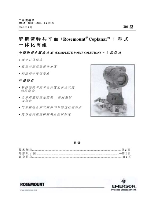
产品规格书 00813-0100-4815 ,AA 版 本
一体化 选项
用于特殊应用场合的清洗
B4 不 锈 钢 安 装 支 架, 适 用2 英 寸 管 , 含300不 锈 钢 螺 栓
L4 奥 氏 体 316 不 锈 钢
典型阀组型号
0301RC32B11B4
典型变送器型号 3051CD2A02A1AS5
(1) 欲 知 更 多 信 息 , 详 见 3051S 型(资 料 号 00813-0100-4801 ) 、3051C 型(资 料 号 00813-0100-4001 ) 与 3095MV 型 变 送 器(资 料 号 00813-0100-4716 )资 料 。
2002 年 5 月
301 型
订货信息
型号 产品描述
0301 R C 3 2 B 1 1 P2
一体化阀组 制造商
罗斯蒙特有限公司 阀组类形
共平面 阀组形式
三阀组 材质 ( 阀体, 阀帽, 阀杆及排液/排气阀) 316 不 锈 钢 过程连接
½-14 NPT 阴 制 锥 管 螺 纹 密封材质
Teflon ( 聚 四 氟 乙 烯 ) 阀组装配
结构材料
阀组 阀 体 、 阀 帽 、 阀 杆 与 排 液 / 排 气 阀 : 316 不 锈 钢
螺栓 符 合 ASTM A449 带 镀 层 的 碳 钢
艾默生 罗斯蒙特 RBI pH ORP 传感器 数据表

产品数据表00813-0106-3008, Rev AD2020 年 9 月罗斯蒙特™ RBI pH/ORP 传感器用于恶劣环境应用的高性能 pH/ORP 测量罗斯蒙特 RBI pH/ORP 传感器采用多重参比液接设计,使之非常适合用在含硫化物及其他有毒离子的恶劣环境应用。
该传感器提供多种配置,能够满足广泛的应用要求。
订购信息罗斯蒙特 RBI pH/ORP 传感器主体材质为 Kynar ®,提供两种配置:一种是 ¾-in. 美制标准管螺纹 (MNPT) 外螺纹直接/浸没式,允许传感器用于 T 型管或浸没储罐;另一种是可插拔式,可以穿过球阀进行各式安装。
高性能和坚固耐用设计■坚固的 Kynar 主体和可选 O 型圈材料 (EPDM 、Viton ® 或Kalrez ™),化学抗性出色。
■可耐受高达 150 psig (1,035 kPa) 的压力■多重参比液接更大程度增加传感器寿命。
易于安装■直接/浸没式主体采用 ¾-in. NPT 前端和后部过程连接,直接安装到过程介质管道中,或连入一个 ¾-in. FNPT 接合延长管用于潜水安装。
■可插拔传感器选件可以插入球阀安装。
通用 VP8 连接■使用 Variopol (VP8) 电缆连接器选件避免了缆线缠绕,实现电缆向传感器快速电缆释放。
在线产品组态工具很多产品可使用我们的产品组态工具进行在线组态。
选择Configure(组态)按钮或访问我们的网站开始。
使用此工具内置的逻辑和持续验证,您可以更快、更准确地度组态您的产品。
内容订购信息 (2)规格...................................................................................................................................................................................................5尺寸图...............................................................................................................................................................................................6附件. (13)罗斯蒙特 RBI2020 年 9 月/Rosemount型号测量类型/电极A10 和 A11 配有 PT100 热电阻 (RTD),用于温度补偿。
罗斯蒙特SAABREX雷达液位计选型中文样本

703010En,第2 版,修订版本B2005 年2 月TankRadar Rex 高精度储罐计量系统703010En,第 2 版,修订版本B TankRadar Rex 2005年 2 月703010En,第2 版,修订版本B2005 年2 月TankRadar Rex703010En,第 2 版,修订版本B TankRadar Rex 2005年 2 月目录Saab TankRadar Rex 适用技术文件:________________________________________________4 本文使用的缩略词:_____________________________________________________________5S aab TankRadar Rex —工业标准储罐计量系统______________________________________6 应用_________________________________________________________________________6 功能概述和系统概览_____________________________________________________________ 7 TankRadar Rex 系统安装和调试____________________________________________________8雷达液位计量___________________________________________________________________9 调频连续波(FMCW)方法__________________________________________________________9 提高精度_____________________________________________________________________10 温度控制__________________________________________________________________10数字参考__________________________________________________________________10无液滴聚集因而不受冷凝影响__________________________________________________10靠近储罐壁的测量___________________________________________________________10用于检测产品表面回波的Saab 专利方法________________________________________11 接触TankRadar Rex 天线发射的微波无健康危险_____________________________________11 防雷保护_____________________________________________________________________11储罐雷达液位计________________________________________________________________12 变送器外壳____________________________________________________________________12 变送器外壳内的电子元件_____________________________________________________12计量密封(选项)___________________________________________________________13变送器外壳的电缆连接_______________________________________________________15 喇叭形天线液位计RTG 3920 _____________________________________________________17 抛物面形天线液位计RTG 3930 ___________________________________________________18 导波管阵列天线液位计RTG 3950 _________________________________________________19 液化石油气/液化天然气(LPG/LNG)液位计RTG 3960 _________________________________20温度测量_____________________________________________________________________22水界面测量____________________________________________________________________25数据采集单元DAU 2100 ________________________________________________________26 本机读出显示器________________________________________________________________26远传显示单元RDU 40 __________________________________________________________27 现场通讯单元FCU 2160 ________________________________________________________28 现场通讯单元FCU 2165/2175 ____________________________________________________30 现场总线调制解调器FBM 2171 ___________________________________________________32 2703010En,第2 版,修订版本B2005 年2 月TankRadar Rex接线盒______________________________________________________________________33 JB 140-11 和JB 140-15,适用于EEx i 和EEx e 环境______________________________33 J B 36 和JB42,用于连接温度传感器______________________________________________33 与温度传感器或水位传感器一体化的接线盒__________________________________________33 配备配管出口的接线盒___________________________________________________________33无线调制解调器________________________________________________________________34T ankMaster 人机界面(HMI)软件__________________________________________________35 微机配置要求__________________________________________________________________37TankMaster 输入/输出(I/O)模块__________________________________________________38 R ex 系统中储罐储量、密度以及混合计算___________________________________________39Saab TankRadar Rex 系统组态___________________________________________________40 T RL/2 总线—快速而可靠的数据总线______________________________________________40 单机应用_____________________________________________________________________41 配备TankMaster 工作站的系统__________________________________________________41 连接现场通讯单元FCU 2160 _____________________________________________________41 冗余_________________________________________________________________________42 一般系统实例__________________________________________________________________43连接其他系统__________________________________________________________________44模拟_________________________________________________________________________45认证_________________________________________________________________________46 精度认证/法定计量认证__________________________________________________________46 危险区域安装认证______________________________________________________________46 辐射排放认证__________________________________________________________________46 其他认证_____________________________________________________________________47 蒸汽对雷达测量的影响___________________________________________________________47专利_________________________________________________________________________483703010En,第 2 版,修订版本B TankRadar Rex 2005年 2 月© 2005 年 2 月,Saab Rosemount Tank Radar AB版权所有。
Rosemount 3144P 温度变送器快速安装指南说明书

快速安装指南00825-0106-4021, Rev SA2022 年 3 月Rosemount™ 3144P 温度变送器采用 HART®协议和 Rosemount X-well™技术快速安装指南2022 年 3 月内容关于本指南 (3)系统准备 (4)验证组态 (5)设置开关 (9)安装变送器 (10)接线和通电 (13)执行回路测试 (19)安全仪表系统 (SIS) (20)产品认证 (21)2Rosemount 3144P2022 年 3 月快速安装指南1关于本指南本指南提供了安装罗斯蒙特3144P 变送器的基本指导。
但未提供详细的组态、诊断、维护、保养、故障排除、防爆、防火或本质安全 (I.S.) 安装的说明。
更多说明,请参阅罗斯蒙特 3144P 变送器参考手册。
手册和本指南的电子版本也可以从/Rosemount获得。
警告爆炸爆炸可能会导致死亡或严重受伤。
在有爆炸危险的环境中安装本设备时,请务必遵守适用的当地、国家和国际标准、规范和规程。
请查阅本文档的“产品认证”一节,了解与安全安装相关的任何限制。
过程泄漏过程泄漏可能导致伤亡。
在加压之前,应安装并拧紧热电偶套管和传感器。
在使用过程中不得拆卸热套管。
导线管/电缆入口变送器外壳中的导线管/电缆入口采用½–14NPT 螺纹牙形。
当在危险场所安装时,在电缆/导线管入口中仅使用已列出或通过 Ex 认证的适当堵头、密封套或接头。
电力停供触电可能会导致死亡或严重伤害。
不得接触引线或接线端子。
引线上可能存在的高压会导致触电。
警告物理接触未经授权的人员可能会对最终用户的设备造成明显受损和/或误组态。
这可能是有意或无意的,需要采取相应的防护措施。
物理安全措施是任何安全计划的重要部分,是保护您的系统的基础。
限制未经授权人员进行物理接触,以保护最终用户的资产。
这对于设施中使用的所有系统均是如此。
快速安装指南3快速安装指南2022 年 3 月2系统准备2.1确认 HART®版本功能若使用基于 HART 的控制系统或资产管理系统,在安装变送器之前,请确认该系统的 HART 功能。
罗斯蒙特差压液位选型样本
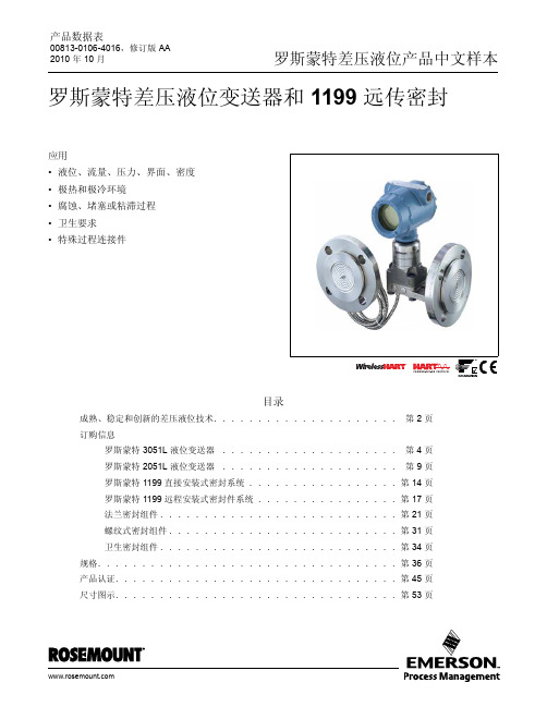
其他信息 规格:第 36 页 认证:第 45 页 尺寸图示:第 53 页
表 1。 罗斯蒙特 3051L 液位变送器订购信息
带★的标准选项为最常用的选项。为了缩短交货期,请选择带星号 ( ★ ) 的选项。 __ 扩展型选项会延长交货期。
甘油和水
1.13
Neobee M-20
0.92
丙二醇和水混合液 1.02
-75 至 145°C (-102 至 293°F) 0 至 205°C (32 至 401°F) -45 至 205°C (-49 至 401°F) -45 至 160°C (-49 至 320°F)
-15 至 95°C (5 至 203°F) -15 至 205°C (5 至 401°F) -15 至 95°C (5 至 203°F)
订 购 液 位 变 送 器 时,您 也 可 额 外 订 购 一 个 1199 远 程 密 封 件,以 组 成 Tuned-System 组件。与传统的对称式系统(平衡)组件相比,Tuned-System 组件性能有所提高,而安装成本有所下降。
产品特性和功能包括:
• 各种过程连接件
• 对整个变送器 / 密封组件提供量化的性能报告 (QZ 选项)
• 毛细管内径尺寸:0.7 毫米 (0.03 英寸)、 1.1 毫 米 (0.04 英寸)及 1.75 毫米 (0.07 英寸)
• 可维修的焊接式结构性能卓越,坚固耐用,适用于 绝大多数应用
• 全焊接式结构适用于高温和高真空应用 (低于 6 psi-a 或 414 mbar-a)
• 热优化器结构适用于过程温度高以及环境温度低 的应用
为什么使用膜片密封件?
艾默生(Emerson) 罗斯蒙特 智能仪表诊断信息参考手册

传感器模块的压力测量值不更新
stopped.
Sensor Module temperature updates have
传感器模块的温度测量值不更新;或温度
stopped or are outside the factory configured 值超出出厂设定的故障极限值。
failure limits.
Process Alerts
Electronics Alarms 电子模件报警 HW/SW Incompatible
Simulation Active Electronics Failure
LCD Failure
NV Memory Failure NV Writes Deferred
3051C Fieldbus and HART Pressure Transmitters (5) AI, AO, ISEL, CHAR, ARITH, INTEG, PID, Description Device Alerts - Passed via DD
(2) AI, ISEL, CHAR, ARITH, INTEG, PID
Description
诊断信息描述
Device Alerts - Passed via DD
主测量值故障 第二测量值故障
传感器模块内存警告
传感器模块内存故障 主测量值超限 第二测量值超限
Pressure updates from the sensor module
Secondary Value Failure
Senor Board NV Memory Failure
Primary Value Degraded
Process Alarms 工艺报警 Reverse Flow Low Flow Cutoff
罗斯蒙特3144P温度变送器中文样本
●
●
目录 用于关键控制和安全应用领域的远程温 度变送器 说明书 Ÿ HART 和 FOUNDATION 现场总 线说明书 Ÿ HART / 4-20 mA 说明书 Ÿ FOUNDATION 现场总线说明书 危险场所认证 尺寸图 订购信息 配置数据表 Ÿ HART / 4-20 mA 变送器 Ÿ FOUNDATION 现场总线变送器
性能
3144P 的性能达到说明书的 3 倍。 稳定性 ● 对于电阻式温度检测器 24 个月内读数误差为 ±0.1% 或 0.1 °C,以较大者为准。 ● 对于热电偶 12 个月内读数误差为 ±0.1% 或 0.1 °C,以较大者为准。 5 年稳定性 ● 对于电阻式温度检测器 5 年内读数误差为 ±0.25% 或 0.25 °C ,以较大者为准。 ● 对于热电偶 5 年内读数误差为 ±0.5% 或 0 .5 °C,以较大者为准。 振动影响 通过下列测试但对性能无影响: 频率 加速度 10.60 Hz 0.21 mm 峰值位移 60.2000 Hz 3 g 自动标定 模/数转换测量电路在每次测量更新时可自动标定,通 过将动态测量结果与极其稳定和准确的内部标准元件 对比来实现。 射频干扰影响 根 据 第 4 页 表 格 按 照 ENV 50140 , 300 V/m (HART) / 10 V/m (FOUNDATION 现场总线), 80 至 1000 MHz,使用非屏蔽电缆进行测试,最差的 射频干扰效应与变送器的标准精度规定相符。 CE 电磁兼容性达标测试 3144P 符合所有 IEC 61326 1998 年第 1 修订版要 求。 外部地脚螺钉组件 外部地脚螺钉组件在外壳指定时可根据指定代码 G1 订购。然而,有的认证在变送器装箱单中包括地脚螺 钉组件。下表明确了哪些认证包括外部地脚螺钉组件。 认证类型 是否包括外部 (1) 地脚螺钉组件?
艾默生 罗斯蒙特144 PC机可编程温度变送器 数据表

2
144C
! 144C
! !"#$%#
!"#$%&$
!"# !"#$%&' ! CD-ROM
3
! DIN
!"
!"#$% ! 00144-0020-0001
71
144
! 144C
! 144C !"# 144 !144C ! 9 25
!
!"#$%& !"#$%&' !"#$%&'()*+,-./ !"#$%&'(
K5
!
!"#
!
KC ! /CSA !"#$% ! !"#$ I II III 1 A B C D ! !"#$% I 2 A B C D ! !"#$%&' 00144-0110 !"# !"#$ -40 C 85 C FM !"#$%&'()* CSA D !"#$ I 1 A B ! !"#$%&' 00144-0120 T4 -40 C Ta 85 C T6 -40 C Ta 60 C GOST GOST PPC 04-9788 EP 1Ex dIIC T6 PPC BA-13006 0 Ex ia IIC T4/T6 !" GOST GOST C
C6
!"#$
CSA
!"#$%&' J5
J6
68
!
! 144
!
! 144
!
! mm(