LT1363CS8中文资料
MAX13085EESA-T中文资料

General DescriptionThe MAX13080E–MAX13089E +5.0V, ±15kV ESD-protect-ed, RS-485/RS-422 transceivers feature one driver and one receiver. These devices include fail-safe circuitry,guaranteeing a logic-high receiver output when receiver inputs are open or shorted. The receiver outputs a logic-high if all transmitters on a terminated bus are disabled (high impedance). The MAX13080E–MAX13089E include a hot-swap capability to eliminate false transitions on the bus during power-up or hot insertion.The MAX13080E/MAX13081E/MAX13082E feature reduced slew-rate drivers that minimize EMI and reduce reflections caused by improperly terminated cables, allowing error-free data transmission up to 250kbps. The MAX13083E/MAX13084E/MAX13085E also feature slew-rate-limited drivers but allow transmit speeds up to 500kbps. The MAX13086E/MAX13087E/MAX13088E driver slew rates are not limited, making transmit speeds up to 16Mbps possible. The MAX13089E slew rate is pin selectable for 250kbps,500kbps, and 16Mbps.The MAX13082E/MAX13085E/MAX13088E are intended for half-duplex communications, and the MAX13080E/MAX13081E/MAX13083E/MAX13084E/MAX13086E/MAX13087E are intended for full-duplex communica-tions. The MAX13089E is selectable for half-duplex or full-duplex operation. It also features independently programmable receiver and transmitter output phase through separate pins.The MAX13080E–MAX13089E transceivers draw 1.2mA of supply current when unloaded or when fully loaded with the drivers disabled. All devices have a 1/8-unit load receiver input impedance, allowing up to 256transceivers on the bus.The MAX13080E/MAX13083E/MAX13086E/MAX13089E are available in 14-pin PDIP and 14-pin SO packages.The MAX13081E/MAX13082E/MAX13084E/MAX13085E/MAX13087E/MAX13088E are available in 8-pin PDIP and 8-pin SO packages. The devices operate over the com-mercial, extended, and automotive temperature ranges.ApplicationsUtility Meters Lighting Systems Industrial Control Telecom Security Systems Instrumentation ProfibusFeatures♦+5.0V Operation♦Extended ESD Protection for RS-485/RS-422 I/O Pins±15kV Human Body Model ♦True Fail-Safe Receiver While Maintaining EIA/TIA-485 Compatibility ♦Hot-Swap Input Structures on DE and RE ♦Enhanced Slew-Rate Limiting Facilitates Error-Free Data Transmission(MAX13080E–MAX13085E/MAX13089E)♦Low-Current Shutdown Mode (Except MAX13081E/MAX13084E/MAX13087E)♦Pin-Selectable Full-/Half-Duplex Operation (MAX13089E)♦Phase Controls to Correct for Twisted-Pair Reversal (MAX13089E)♦Allow Up to 256 Transceivers on the Bus ♦Available in Industry-Standard 8-Pin SO PackageMAX13080E–MAX13089E+5.0V , ±15kV ESD-Protected, Fail-Safe, Hot-Swap, RS-485/RS-422 Transceivers________________________________________________________________Maxim Integrated Products 1Ordering Information19-3590; Rev 1; 4/05For pricing, delivery, and ordering information,please contact Maxim/Dallas Direct!at 1-888-629-4642, or visit Maxim’s website at .Selector Guide, Pin Configurations, and Typical Operating Circuits appear at end of data sheet.Ordering Information continued at end of data sheet.M A X 13080E –M A X 13089E+5.0V , ±15kV ESD-Protected, Fail-Safe, Hot-Swap, RS-485/RS-422 Transceivers 2_______________________________________________________________________________________ABSOLUTE MAXIMUM RATINGSDC ELECTRICAL CHARACTERISTICS(V CC = +5.0V ±10%, T A = T MIN to T MAX , unless otherwise noted. Typical values are at V CC = +5.0V and T A = +25°C.) (Note 1)Stresses beyond those listed under “Absolute Maximum Ratings” may cause permanent damage to the device. These are stress ratings only, and functional operation of the device at these or any other conditions beyond those indicated in the operational sections of the specifications is not implied. Exposure to absolute maximum rating conditions for extended periods may affect device reliability.(All Voltages Referenced to GND)Supply Voltage (V CC ).............................................................+6V Control Input Voltage (RE , DE, SLR,H/F , TXP, RXP)......................................................-0.3V to +6V Driver Input Voltage (DI)...........................................-0.3V to +6V Driver Output Voltage (Z, Y, A, B).............................-8V to +13V Receiver Input Voltage (A, B)....................................-8V to +13V Receiver Input VoltageFull Duplex (A, B)..................................................-8V to +13V Receiver Output Voltage (RO)....................-0.3V to (V CC + 0.3V)Driver Output Current.....................................................±250mAContinuous Power Dissipation (T A = +70°C)8-Pin SO (derate 5.88mW/°C above +70°C).................471mW 8-Pin Plastic DIP (derate 9.09mW/°C above +70°C).....727mW 14-Pin SO (derate 8.33mW/°C above +70°C)...............667mW 14-Pin Plastic DIP (derate 10.0mW/°C above +70°C)...800mW Operating Temperature RangesMAX1308_EC_ _.................................................0°C to +75°C MAX1308_EE_ _..............................................-40°C to +85°C MAX1308_EA_ _............................................-40°C to +125°C Junction Temperature......................................................+150°C Storage Temperature Range.............................-65°C to +150°C Lead Temperature (soldering, 10s).................................+300°CMAX13080E–MAX13089E+5.0V , ±15kV ESD-Protected, Fail-Safe, Hot-Swap, RS-485/RS-422 Transceivers_______________________________________________________________________________________3DC ELECTRICAL CHARACTERISTICS (continued)(V CC = +5.0V ±10%, T A = T MIN to T MAX , unless otherwise noted. Typical values are at V CC = +5.0V and T A = +25°C.) (Note 1)M A X 13080E –M A X 13089E+5.0V , ±15kV ESD-Protected, Fail-Safe, Hot-Swap, RS-485/RS-422 Transceivers 4_______________________________________________________________________________________DRIVER SWITCHING CHARACTERISTICSMAX13080E/MAX13081E/MAX13082E/MAX13089E WITH SRL = UNCONNECTED (250kbps)(V CC = +5.0V ±10%, T A = T MIN to T MAX , unless otherwise noted. Typical values are at V CC = +5.0V and T A = +25°C.)RECEIVER SWITCHING CHARACTERISTICSMAX13080E/MAX13081E/MAX13082E/MAX13089E WITH SRL = UNCONNECTED (250kbps)(V CC = +5.0V ±10%, T A = T MIN to T MAX , unless otherwise noted. Typical values are at V CC = +5.0V and T A = +25°C.)MAX13080E–MAX13089E+5.0V , ±15kV ESD-Protected, Fail-Safe, Hot-Swap, RS-485/RS-422 Transceivers_______________________________________________________________________________________5DRIVER SWITCHING CHARACTERISTICSMAX13083E/MAX13084E/MAX13085E/MAX13089E WITH SRL = V CC (500kbps)(V CC = +5.0V ±10%, T A = T MIN to T MAX , unless otherwise noted. Typical values are at V CC = +5.0V and T A = +25°C.)RECEIVER SWITCHING CHARACTERISTICSMAX13083E/MAX13084E/MAX13085E/MAX13089E WITH SRL = V CC (500kbps)(V CC = +5.0V ±10%, T A = T MIN to T MAX , unless otherwise noted. Typical values are at V CC = +5.0V and T A = +25°C.)M A X 13080E –M A X 13089E+5.0V , ±15kV ESD-Protected, Fail-Safe, Hot-Swap, RS-485/RS-422 Transceivers 6_______________________________________________________________________________________DRIVER SWITCHING CHARACTERISTICSMAX13086E/MAX13087E/MAX13088E/MAX13089E WITH SRL = GND (16Mbps)(V CC = +5.0V ±10%, T A = T MIN to T MAX , unless otherwise noted. Typical values are at V CC = +5.0V and T A = +25°C.)RECEIVER SWITCHING CHARACTERISTICSMAX13086E/MAX13087E/MAX13088E/MAX13089E WITH SRL = GND (16Mbps)(V CC = +5.0V ±10%, T A = T MIN to T MAX , unless otherwise noted. Typical values are at V CC = +5.0V and T A = +25°C.)Note 2:∆V OD and ∆V OC are the changes in V OD and V OC , respectively, when the DI input changes state.Note 3:The short-circuit output current applies to peak current just prior to foldback current limiting. The short-circuit foldback outputcurrent applies during current limiting to allow a recovery from bus contention.MAX13080E–MAX13089E+5.0V , ±15kV ESD-Protected, Fail-Safe, Hot-Swap, RS-485/RS-422 Transceivers_______________________________________________________________________________________70.800.901.501.101.001.201.301.401.60-40-10520-253550958011065125SUPPLY CURRENT vs. TEMPERATURETEMPERATURE (°C)S U P P L Y C U R R E N T (m A )0201040305060021345OUTPUT CURRENTvs. RECEIVER OUTPUT-HIGH VOLTAGEM A X 13080E -89E t o c 02OUTPUT HIGH VOLTAGE (V)O U T P U T C U R R E N T (m A )20104030605070021345OUTPUT CURRENTvs. RECEIVER OUTPUT-LOW VOLTAGEM A X 13080E -89E t o c 03OUTPUT LOW VOLTAGE (V)O U T P U T C U R R E N T (m A )4.04.44.24.84.65.25.05.4RECEIVER OUTPUT-HIGH VOLTAGEvs. TEMPERATURETEMPERATURE (°C)O U T P U T H I G H V O L T A G E (V )-40-10520-2535509580110651250.10.70.30.20.40.50.60.8RECEIVER OUTPUT-LOW VOLTAGEvs. TEMPERATURETEMPERATURE (°C)O U T P U T L O W V O L T A G E (V )-40-10520-25355095801106512502040608010012014016012345DRIVER DIFFERENTIAL OUTPUT CURRENT vs. DIFFERENTIAL OUTPUT VOLTAGEDIFFERENTIAL OUTPUT VOLTAGE (V)D I F FE R E N T I A L O U T P U T C U R R E N T (m A )2.02.82.43.63.24.44.04.8DRIVER DIFFERENTIAL OUTPUT VOLTAGE vs. TEMPERATURED I F FE R E N T I A L O U T P U T V O L T A G E (V )-40-10520-253550958011065125TEMPERATURE (°C)40201008060120140180160200-7-5-4-6-3-2-1012354OUTPUT CURRENT vs. TRANSMITTEROUTPUT-HIGH VOLTAGEOUTPUT HIGH VOLTAGE (V)O U T P U T C U R R E N T (m A )60402080100120140160180200042681012OUTPUT CURRENT vs. TRANSMITTEROUTPUT-LOW VOLTAGEOUTPUT-LOW VOLTAGE (V)O U T P U T C U R R E N T (m A )Typical Operating Characteristics(V CC = +5.0V, T A = +25°C, unless otherwise noted.)M A X 13080E –M A X 13089E+5.0V , ±15kV ESD-Protected, Fail-Safe, Hot-Swap, RS-485/RS-422 Transceivers 8_______________________________________________________________________________________21543679810SHUTDOWN CURRENT vs. TEMPERATUREM A X 13080E -89E t o c 10S H U T D O W N C U R R E N T (µA )-40-10520-253550958011065125TEMPERATURE (°C)600800700100090011001200DRIVER PROPAGATION DELAY vs. TEMPERATURE (250kbps)D R I VE R P R O P A G A T I O N D E L A Y (n s )-40-10520-253550958011065125TEMPERATURE (°C)300400350500450550600DRIVER PROPAGATION DELAY vs. TEMPERATURE (500kbps)D R I VE R P R O P A G A T I O N D E L A Y (n s )-40-10520-253550958011065125TEMPERATURE (°C)1070302040506080DRIVER PROPAGATION DELAY vs. TEMPERATURE (16Mbps)D R I VE R P R O P A G A T I O N D E L A Y (n s )-40-10520-253550958011065125TEMPERATURE (°C)40201008060120140160180RECEIVER PROPAGATION DELAYvs. TEMPERATURE (250kpbs AND 500kbps)R E C E I V E R P R O P A G A T I O N D E L A Y (n s )-40-10520-253550958011065125TEMPERATURE (°C)40201008060120140160180RECEIVER PROPAGATION DELAYvs. TEMPERATURE (16Mbps)R EC E I V E R P R O P A G AT I O N D E L A Y (n s )-40-10520-253550958011065125TEMPERATURE (°C)2µs/div DRIVER PROPAGATION DELAY (250kbps)DI 2V/divV Y - V Z 5V/divR L = 100Ω200ns/divRECEIVER PROPAGATION DELAY(250kbps AND 500kbps)V A - V B 5V/divRO 2V/divTypical Operating Characteristics (continued)(V CC = +5.0V, T A = +25°C, unless otherwise noted.)MAX13080E–MAX13089E+5.0V , ±15kV ESD-Protected, Fail-Safe, Hot-Swap, RS-485/RS-422 Transceivers_______________________________________________________________________________________9Test Circuits and Waveforms400ns/divDRIVER PROPAGATION DELAY (500kbps)DI 2V/divR L = 100ΩV Y - V Z 5V/div10ns/div DRIVER PROPAGATION DELAY (16Mbps)DI 2V/divR L = 100ΩV Y 2V/divV Z 2V/div40ns/divRECEIVER PROPAGATION DELAY (16Mbps)V B 2V/divR L = 100ΩRO 2V/divV A 2V/divTypical Operating Characteristics (continued)(V CC = +5.0V, T A = +25°C, unless otherwise noted.)Figure 2. Driver Timing Test CircuitM A X 13080E –M A X 13089E+5.0V , ±15kV ESD-Protected, Fail-Safe, Hot-Swap, RS-485/RS-422 Transceivers 10______________________________________________________________________________________Test Circuits and Waveforms (continued)Figure 4. Driver Enable and Disable Times (t DHZ , t DZH , t DZH(SHDN))DZL DLZ DLZ(SHDN)MAX13080E–MAX13089E+5.0V , ±15kV ESD-Protected, Fail-Safe, Hot-Swap, RS-485/RS-422 TransceiversTest Circuits and Waveforms (continued)Figure 6. Receiver Propagation Delay Test CircuitM A X 13080E –M A X 13089E+5.0V , ±15kV ESD-Protected, Fail-Safe, Hot-Swap, RS-485/RS-422 TransceiversMAX13080E–MAX13089E+5.0V , ±15kV ESD-Protected, Fail-Safe, Hot-Swap, RS-485/RS-422 TransceiversMAX13080E/MAX13083E/MAX13086EMAX13081E/MAX13084E/MAX13086E/MAX13087EFunction TablesM A X 13080E –M A X 13089E+5.0V , ±15kV ESD-Protected, Fail-Safe, Hot-Swap, RS-485/RS-422 Transceivers MAX13082E/MAX13085E/MAX13088EFunction Tables (continued)MAX13089EDetailed Description The MAX13080E–MAX13089E high-speed transceivers for RS-485/RS-422 communication contain one driver and one receiver. These devices feature fail-safe circuit-ry, which guarantees a logic-high receiver output when the receiver inputs are open or shorted, or when they are connected to a terminated transmission line with all dri-vers disabled (see the Fail-Safe section). The MAX13080E/MAX13082E/MAX13083E/MAX13085E/ MAX13086E/MAX13088E/MAX13089E also feature a hot-swap capability allowing line insertion without erroneous data transfer (see the Hot Swap Capability section). The MAX13080E/MAX13081E/MAX13082E feature reduced slew-rate drivers that minimize EMI and reduce reflec-tions caused by improperly terminated cables, allowing error-free data transmission up to 250kbps. The MAX13083E/MAX13084E/MAX13085E also offer slew-rate limits allowing transmit speeds up to 500kbps. The MAX13086E/MAX13087E/MAX13088Es’ driver slew rates are not limited, making transmit speeds up to 16Mbps possible. The MAX13089E’s slew rate is selectable between 250kbps, 500kbps, and 16Mbps by driving a selector pin with a three-state driver.The MAX13082E/MAX13085E/MAX13088E are half-duplex transceivers, while the MAX13080E/MAX13081E/ MAX13083E/MAX13084E/MAX13086E/MAX13087E are full-duplex transceivers. The MAX13089E is selectable between half- and full-duplex communication by driving a selector pin (H/F) high or low, respectively.All devices operate from a single +5.0V supply. Drivers are output short-circuit current limited. Thermal-shutdown circuitry protects drivers against excessive power dissi-pation. When activated, the thermal-shutdown circuitry places the driver outputs into a high-impedance state.Receiver Input Filtering The receivers of the MAX13080E–MAX13085E, and the MAX13089E when operating in 250kbps or 500kbps mode, incorporate input filtering in addition to input hysteresis. This filtering enhances noise immunity with differential signals that have very slow rise and fall times. Receiver propagation delay increases by 25% due to this filtering.Fail-Safe The MAX13080E family guarantees a logic-high receiver output when the receiver inputs are shorted or open, or when they are connected to a terminated transmission line with all drivers disabled. This is done by setting the receiver input threshold between -50mV and -200mV. If the differential receiver input voltage (A - B) is greater than or equal to -50mV, RO is logic-high. If (A - B) is less than or equal to -200mV, RO is logic-low. In the case of a terminated bus with all transmitters disabled, the receiv-er’s differential input voltage is pulled to 0V by the termi-nation. With the receiver thresholds of the MAX13080E family, this results in a logic-high with a 50mV minimumnoise margin. Unlike previous fail-safe devices, the-50mV to -200mV threshold complies with the ±200mVEIA/TIA-485 standard.Hot-Swap Capability (Except MAX13081E/MAX13084E/MAX13087E)Hot-Swap InputsWhen circuit boards are inserted into a hot or powered backplane, differential disturbances to the data buscan lead to data errors. Upon initial circuit board inser-tion, the data communication processor undergoes itsown power-up sequence. During this period, the processor’s logic-output drivers are high impedanceand are unable to drive the DE and RE inputs of these devices to a defined logic level. Leakage currents up to±10µA from the high-impedance state of the proces-sor’s logic drivers could cause standard CMOS enableinputs of a transceiver to drift to an incorrect logic level. Additionally, parasitic circuit board capacitance couldcause coupling of V CC or GND to the enable inputs. Without the hot-swap capability, these factors could improperly enable the transceiver’s driver or receiver.When V CC rises, an internal pulldown circuit holds DElow and RE high. After the initial power-up sequence,the pulldown circuit becomes transparent, resetting thehot-swap tolerable input.Hot-Swap Input CircuitryThe enable inputs feature hot-swap capability. At theinput there are two NMOS devices, M1 and M2 (Figure 9). When V CC ramps from zero, an internal 7µstimer turns on M2 and sets the SR latch, which alsoturns on M1. Transistors M2, a 1.5mA current sink, andM1, a 500µA current sink, pull DE to GND through a5kΩresistor. M2 is designed to pull DE to the disabledstate against an external parasitic capacitance up to100pF that can drive DE high. After 7µs, the timer deactivates M2 while M1 remains on, holding DE low against three-state leakages that can drive DE high. M1 remains on until an external source overcomes the required input current. At this time, the SR latch resetsand M1 turns off. When M1 turns off, DE reverts to a standard, high-impedance CMOS input. Whenever V CCdrops below 1V, the hot-swap input is reset.For RE there is a complementary circuit employing two PMOS devices pulling RE to V CC. MAX13080E–MAX13089E+5.0V, ±15kV ESD-Protected, Fail-Safe, Hot-Swap, RS-485/RS-422 TransceiversM A X 13080E –M A X 13089EMAX13089E ProgrammingThe MAX13089E has several programmable operating modes. Transmitter rise and fall times are programma-ble, resulting in maximum data rates of 250kbps,500kbps, and 16Mbps. To select the desired data rate,drive SRL to one of three possible states by using a three-state driver: V CC , GND, or unconnected. F or 250kbps operation, set the three-state device in high-impedance mode or leave SRL unconnected. F or 500kbps operation, drive SRL high or connect it to V CC .F or 16Mbps operation, drive SRL low or connect it to GND. SRL can be changed during operation without interrupting data communications.Occasionally, twisted-pair lines are connected backward from normal orientation. The MAX13089E has two pins that invert the phase of the driver and the receiver to cor-rect this problem. F or normal operation, drive TXP and RXP low, connect them to ground, or leave them uncon-nected (internal pulldown). To invert the driver phase,drive TXP high or connect it to V CC . To invert the receiver phase, drive RXP high or connect it to V CC . Note that the receiver threshold is positive when RXP is high.The MAX13089E can operate in full- or half-duplex mode. Drive H/F low, leave it unconnected (internal pulldown), or connect it to GND for full-duplex opera-tion. Drive H/F high for half-duplex operation. In full-duplex mode, the pin configuration of the driver and receiver is the same as that of a MAX13080E. In half-duplex mode, the receiver inputs are internally connect-ed to the driver outputs through a resistor-divider. This effectively changes the function of the device’s outputs.Y becomes the noninverting driver output and receiver input, Z becomes the inverting driver output and receiver input. In half-duplex mode, A and B are still connected to ground through an internal resistor-divider but they are not internally connected to the receiver.±15kV ESD ProtectionAs with all Maxim devices, ESD-protection structures are incorporated on all pins to protect against electro-static discharges encountered during handling and assembly. The driver outputs and receiver inputs of the MAX13080E family of devices have extra protection against static electricity. Maxim’s engineers have devel-oped state-of-the-art structures to protect these pins against ESD of ±15kV without damage. The ESD struc-tures withstand high ESD in all states: normal operation,shutdown, and powered down. After an ESD event, the MAX13080E–MAX13089E keep working without latchup or damage.ESD protection can be tested in various ways. The transmitter outputs and receiver inputs of the MAX13080E–MAX13089E are characterized for protec-tion to the following limits:•±15kV using the Human Body Model•±6kV using the Contact Discharge method specified in IEC 61000-4-2ESD Test ConditionsESD performance depends on a variety of conditions.Contact Maxim for a reliability report that documents test setup, test methodology, and test results.Human Body ModelFigure 10a shows the Human Body Model, and Figure 10b shows the current waveform it generates when dis-charged into a low impedance. This model consists of a 100pF capacitor charged to the ESD voltage of interest,which is then discharged into the test device through a 1.5k Ωresistor.IEC 61000-4-2The IEC 61000-4-2 standard covers ESD testing and performance of finished equipment. However, it does not specifically refer to integrated circuits. The MAX13080E family of devices helps you design equip-ment to meet IEC 61000-4-2, without the need for addi-tional ESD-protection components.+5.0V , ±15kV ESD-Protected, Fail-Safe, Hot-Swap, RS-485/RS-422 TransceiversThe major difference between tests done using the Human Body Model and IEC 61000-4-2 is higher peak current in IEC 61000-4-2 because series resistance is lower in the IEC 61000-4-2 model. Hence, the ESD with-stand voltage measured to IEC 61000-4-2 is generally lower than that measured using the Human Body Model. Figure 10c shows the IEC 61000-4-2 model, and Figure 10d shows the current waveform for IEC 61000-4-2 ESD Contact Discharge test.Machine Model The machine model for ESD tests all pins using a 200pF storage capacitor and zero discharge resis-tance. The objective is to emulate the stress caused when I/O pins are contacted by handling equipment during test and assembly. Of course, all pins require this protection, not just RS-485 inputs and outputs.Applications Information256 Transceivers on the BusThe standard RS-485 receiver input impedance is 12kΩ(1-unit load), and the standard driver can drive up to 32-unit loads. The MAX13080E family of transceivers has a1/8-unit load receiver input impedance (96kΩ), allowingup to 256 transceivers to be connected in parallel on one communication line. Any combination of these devices,as well as other RS-485 transceivers with a total of 32-unit loads or fewer, can be connected to the line.Reduced EMI and ReflectionsThe MAX13080E/MAX13081E/MAX13082E feature reduced slew-rate drivers that minimize EMI and reduce reflections caused by improperly terminated cables, allowing error-free data transmission up to250kbps. The MAX13083E/MAX13084E/MAX13085Eoffer higher driver output slew-rate limits, allowing transmit speeds up to 500kbps. The MAX13089E withSRL = V CC or unconnected are slew-rate limited. WithSRL unconnected, the MAX13089E error-free data transmission is up to 250kbps. With SRL connected toV CC,the data transmit speeds up to 500kbps. MAX13080E–MAX13089E+5.0V, ±15kV ESD-Protected, Fail-Safe, Hot-Swap, RS-485/RS-422 TransceiversM A X 13080E –M A X 13089ELow-Power Shutdown Mode (Except MAX13081E/MAX13084E/MAX13087E)Low-power shutdown mode is initiated by bringing both RE high and DE low. In shutdown, the devices typically draw only 2.8µA of supply current.RE and DE can be driven simultaneously; the devices are guaranteed not to enter shutdown if RE is high and DE is low for less than 50ns. If the inputs are in this state for at least 700ns, the devices are guaranteed to enter shutdown.Enable times t ZH and t ZL (see the Switching Characteristics section) assume the devices were not in a low-power shutdown state. Enable times t ZH(SHDN)and t ZL(SHDN)assume the devices were in shutdown state. It takes drivers and receivers longer to become enabled from low-power shutdown mode (t ZH(SHDN), t ZL(SHDN))than from driver/receiver-disable mode (t ZH , t ZL ).Driver Output ProtectionTwo mechanisms prevent excessive output current and power dissipation caused by faults or by bus contention.The first, a foldback current limit on the output stage,provides immediate protection against short circuits over the whole common-mode voltage range (see the Typical Operating Characteristics ). The second, a thermal-shut-down circuit, forces the driver outputs into a high-imped-ance state if the die temperature exceeds +175°C (typ).Line LengthThe RS-485/RS-422 standard covers line lengths up to 4000ft. F or line lengths greater than 4000ft, use the repeater application shown in Figure 11.Typical ApplicationsThe MAX13082E/MAX13085E/MAX13088E/MAX13089E transceivers are designed for bidirectional data commu-nications on multipoint bus transmission lines. F igures 12 and 13 show typical network applications circuits. To minimize reflections, terminate the line at both ends in its characteristic impedance, and keep stub lengths off the main line as short as possible. The slew-rate-lim-ited MAX13082E/MAX13085E and the two modes of the MAX13089E are more tolerant of imperfect termination.Chip InformationTRANSISTOR COUNT: 1228PROCESS: BiCMOS+5.0V , ±15kV ESD-Protected, Fail-Safe, Hot-Swap, RS-485/RS-422 TransceiversFigure 11. Line Repeater for MAX13080E/MAX13081E/MAX13083E/MAX13084E/MAX13086E/MAX13087E/MAX13089E in Full-Duplex Mode+5.0V, ±15kV ESD-Protected, Fail-Safe, Hot-Swap, RS-485/RS-422 TransceiversMAX13080E–MAX13089EM A X 13080E –M A X 13089E+5.0V , ±15kV ESD-Protected, Fail-Safe, Hot-Swap, RS-485/RS-422 TransceiversPin Configurations and Typical Operating CircuitsMAX13080E–MAX13089E+5.0V , ±15kV ESD-Protected, Fail-Safe, Hot-Swap, RS-485/RS-422 Transceivers______________________________________________________________________________________21Pin Configurations and Typical Operating Circuits (continued)M A X 13080E –M A X 13089E+5.0V , ±15kV ESD-Protected, Fail-Safe, Hot-Swap, RS-485/RS-422 Transceivers 22______________________________________________________________________________________Ordering Information (continued)MAX13080E–MAX13089E+5.0V , ±15kV ESD-Protected, Fail-Safe, Hot-Swap, RS-485/RS-422 Transceivers______________________________________________________________________________________23Package Information (continued)(The package drawing(s) in this data sheet may not reflect the most current specifications. For the latest package outline information,go to /packages .)。
CS42438_07中文资料

FEATURESSix 24-bit A/D, Eight 24-bit D/A Converters ADC Dynamic Range–105 dB Differential –102 dB Single-Ended DAC Dynamic Range–108 dB Differential –105 dB Single-Ended ADC/DAC THD+N–-98 dB Differential –-95 dB Single-EndedCompatible with Industry-Standard TimeDivision Multiplexed (TDM) Serial InterfaceDAC Sampling Rates up to 192 kHz ADC Sampling Rates up to 96 kHzProgrammable ADC High-Pass Filter for DCOffset CalibrationLogarithmic Digital Volume Control Hardware Mode or Software I²C ® & SPI ™ Supports Logic Levels Between 5V and 1.8VGENERAL DESCRIPTIONThe CS42438 CODEC provides six multi-bit analog-to-digital and eight multi-bit digital-to-analog delta-sigma converters. The CODEC is capable of operation with ei-ther differential or single-ended inputs and outputs, in a 52-pin MQFP package.Six fully differential, or single-ended, inputs are avail-able on stereo ADC1, ADC2, and ADC3. When operating in Single-Ended Mode, an internal MUX be-fore ADC3 allows selection from up to four single-ended inputs. Digital volume control is provided for each ADC channel, with selectable overflow detection.All eight DAC channels provide digital volume control and can operate with differential or single-ended outputs.An auxiliary serial input is available for an additional two channels of PCM data.The CS42438 is available in a 52-pin MQFP package in Commercial (-10°C to +70°C) and Automotive (-40°C to +105°C) grades. The CDB42438 Customer Demonstra-tion board is also available for device evaluation and implementation suggestions. Please refer to “Ordering Information” on page 61 for complete ordering information.The CS42438 is ideal for audio systems requiring wide dynamic range, negligible distortion and low noise, such as A/V receivers, DVD receivers, and automotive audio systems.CS42438TABLE OF CONTENTS1. PIN DESCRIPTIONS - SOFTWARE MODE (6)1.1 Digital I/O Pin Characteristics (8)2. PIN DESCRIPTIONS - HARDWARE MODE (9)3. TYPICAL CONNECTION DIAGRAMS (11)4. CHARACTERISTICS AND SPECIFICATIONS (13)RECOMMENDED OPERATING CONDITIONS (13)ABSOLUTE MAXIMUM RATINGS (13)ANALOG INPUT CHARACTERISTICS (COMMERCIAL) (14)ANALOG INPUT CHARACTERISTICS (AUTOMOTIVE) (15)ADC DIGITAL FILTER CHARACTERISTICS (16)ANALOG OUTPUT CHARACTERISTICS (COMMERCIAL) (17)ANALOG OUTPUT CHARACTERISTICS (AUTOMOTIVE) (18)COMBINED DAC INTERPOLATION & ON-CHIP ANALOG FILTER RESPONSE (20)SWITCHING SPECIFICATIONS - ADC/DAC PORT (21)SWITCHING CHARACTERISTICS - AUX PORT (22)SWITCHING SPECIFICATIONS - CONTROL PORT - I²C MODE (23)SWITCHING SPECIFICATIONS - CONTROL PORT - SPI FORMAT (24)DC ELECTRICAL CHARACTERISTICS (25)DIGITAL INTERFACE SPECIFICATIONS & CHARACTERISTICS (25)5. APPLICATIONS (26)5.1 Overview (26)5.2 Analog Inputs (27)5.2.1 Line-Level Inputs (27)5.2.1.1 Hardware Mode (27)5.2.1.2 Software Mode (27)5.2.2 ADC3 Analog Input (28)5.2.3 Hardware Mode (29)5.2.4 Software Mode (29)5.2.5 High-Pass Filter and DC Offset Calibration (29)5.2.5.1 Hardware Mode (29)5.2.5.2 Software Mode (29)5.3 Analog Outputs (30)5.3.1 Initialization (30)5.3.2 Line-Level Outputs and Filtering (30)5.3.3 Digital Volume Control (32)5.3.3.1 Hardware Mode (32)5.3.3.2 Software Mode (32)5.3.4 De-Emphasis Filter (32)5.4 System Clocking (33)5.4.1 Hardware Mode (33)5.4.2 Software Mode (33)5.5 CODEC Digital Interface (33)5.5.1 TDM (33)5.5.2 I/O Channel Allocation (34)5.6 AUX Port Digital Interface Formats (34)5.6.1 Hardware Mode (34)5.6.2 Software Mode (34)5.6.3 I²S (34)5.6.4 Left-Justified (35)5.7 Control Port Description and Timing (35)5.7.1 SPI Mode (35)5.7.2 I²C Mode (36)5.8 Recommended Power-Up Sequence (37)5.8.1 Hardware Mode (37)5.8.2 Software Mode (38)5.9 Reset and Power-Up (38)5.10 Power Supply, Grounding, and PCB Layout (38)6. REGISTER QUICK REFERENCE (39)7. REGISTER DESCRIPTION (41)7.1 Memory Address Pointer (MAP) (41)7.1.1 Increment (INCR) (41)7.1.2 Memory Address Pointer (MAP[6:0]) (41)7.2 Chip I.D. and Revision Register (Address 01h) (Read Only) (41)7.2.1 Chip I.D. (CHIP_ID[3:0]) (41)7.2.2 Chip Revision (REV_ID[3:0]) (41)7.3 Power Control (Address 02h) (42)7.3.1 Power Down ADC Pairs (PDN_ADCX) (42)7.3.2 Power Down DAC Pairs (PDN_DACX) (42)7.3.3 Power Down (PDN) (42)7.4 Functional Mode (Address 03h) (43)7.4.1 MCLK Frequency (MFREQ[2:0]) (43)7.5 Miscellaneous Control (Address 04h) (43)7.5.1 Freeze Controls (FREEZE) (43)7.5.2 Auxiliary Digital Interface Format (AUX_DIF) (43)7.6 ADC Control & DAC De-Emphasis (Address 05h) (44)7.6.1 ADC1-2 High-Pass Filter Freeze (ADC1-2_HPF FREEZE) (44)7.6.2 ADC3 High Pass Filter Freeze (ADC3_HPF FREEZE) (44)7.6.3 DAC De-Emphasis Control (DAC_DEM) (44)7.6.4 ADC1 Single-Ended Mode (ADC1 SINGLE) (44)7.6.5 ADC2 Single-Ended Mode (ADC2 SINGLE) (44)7.6.6 ADC3 Single-Ended Mode (ADC3 SINGLE) (45)7.6.7 Analog Input Ch. 5 Multiplexer (AIN5_MUX) (45)7.6.8 Analog Input Ch. 6 Multiplexer (AIN6_MUX) (45)7.7 Transition Control (Address 06h) (45)7.7.1 Single Volume Control (DAC_SNGVOL, ADC_SNGVOL) (45)7.7.2 Soft Ramp and Zero Cross Control (ADC_SZC[1:0], DAC_SZC[1:0]) (46)7.7.3 Auto-Mute (AMUTE) (46)7.7.4 Mute ADC Serial Port (MUTE ADC_SP) (47)7.8 DAC Channel Mute (Address 07h) (47)7.8.1 Independent Channel Mute (AOUTX_MUTE) (47)7.9 AOUTX Volume Control (Addresses 08h- 0Fh) (47)7.9.1 Volume Control (AOUTX_VOL[7:0]) (47)7.10 DAC Channel Invert (Address 10h) (48)7.10.1 Invert Signal Polarity (INV_AOUTX) (48)7.11 AINX Volume Control (Address 11h-16h) (48)7.11.1 AINX Volume Control (AINX_VOL[7:0]) (48)7.12 ADC Channel Invert (Address 17h) (49)7.12.1 Invert Signal Polarity (INV_AINX) (49)7.13 Status (Address 19h) (Read Only) (49)7.13.1 CLOCK ERROR (CLK ERROR) (49)7.13.2 ADC Overflow (ADCX_OVFL) (49)7.14 Status Mask (Address 1Ah) (49)8. EXTERNAL FILTERS (50)8.1 ADC Input Filter (50)8.1.1 Passive Input Filter (51)8.1.2 Passive Input Filter w/Attenuation (52)9. ADC FILTER PLOTS (54)10. DAC FILTER PLOTS (56)11. PARAMETER DEFINITIONS (58)12. REFERENCES (59)13. PACKAGE INFORMATION (60)13.1 Thermal Characteristics (60)14. ORDERING INFORMATION (61)15. REVISION HISTORY (61)LIST OF FIGURESFigure 1.Typical Connection Diagram (Software Mode) (11)Figure 2.Typical Connection Diagram (Hardware Mode) (12)Figure 3.Output Test Circuit for Maximum Load (19)Figure 4.Maximum Loading (19)Figure 5.TDM Serial Audio Interface Timing (21)Figure 6.Serial Audio Interface Slave Mode Timing (22)Figure 7.Control Port Timing - I²C Format (23)Figure 8.Control Port Timing - SPI Format (24)Figure 9.Full-Scale Input (28)Figure 10.ADC3 Input Topology (28)Figure 11.Audio Output Initialization Flow Chart (31)Figure 12.Full-Scale Output (32)Figure 13.De-Emphasis Curve (33)Figure 14.TDM Serial Audio Format (34)Figure 15.AUX I²S Format (34)Figure 16.AUX Left-Justified Format (35)Figure 17.Control Port Timing in SPI Mode (36)Figure 18.Control Port Timing, I²C Write (36)Figure 19.Control Port Timing, I²C Read (37)Figure 20.Single to Differential Active Input Filter (50)Figure 21.Single-Ended Active Input Filter (50)Figure 22.Passive Input Filter (51)Figure 23.Passive Input Filter w/Attenuation (52)Figure 24.Active Analog Output Filter (53)Figure 25.Passive Analog Output Filter (53)Figure 26.SSM Stopband Rejection (54)Figure 27.SSM Transition Band (54)Figure 28.SSM Transition Band (Detail) (54)Figure 29.SSM Passband Ripple (54)Figure 30.DSM Stopband Rejection (54)Figure 31.DSM Transition Band (54)Figure 32.DSM Transition Band (Detail) (55)Figure 33.DSM Passband Ripple (55)Figure 34.SSM Stopband Rejection (56)Figure 35.SSM Transition Band (56)Figure 36.SSM Transition Band (detail) (56)Figure 37.SSM Passband Ripple (56)Figure 38.DSM Stopband Rejection (56)Figure 39.DSM Transition Band (56)Figure 40.DSM Transition Band (detail) (57)Figure 41.DSM Passband Ripple (57)Figure 42.QSM Stopband Rejection (57)Figure 44.QSM Transition Band (detail) (57)Figure 45.QSM Passband Ripple (57)LIST OF TABLESTable 1. I/O Power Rails (8)Table 2. Hardware Configurable Settings (26)Table 3. AIN5 Analog Input Selection (29)Table 4. AIN6 Analog Input Selection (29)Table 5. MCLK Frequency Settings (33)Table 6. Serial Audio Interface Channel Allocations (34)Table 7. MCLK Frequency Settings (43)Table 8. Example AOUT Volume Settings (47)Table 9. Example AIN Volume Settings (48)1.PIN DESCRIPTIONS - SOFTWARE MODEPin Name#Pin DescriptionSCL/CCLK1Serial Control Port Clock (Input) - Serial clock for the control port interface.SDA/CDOUT2Serial Control Data I/O (Input/Output) - Input/Output for I²C data. Output for SPI data.AD0/CS3Address Bit [0]/ Chip Select (Input) - Chip address bit in I²C Mode. Control signal used to select the chip in SPI Mode.AD1/CDIN4Address Bit [1]/ SPI Data Input (Input) - Chip address bit in I²C Mode. Input for SPI data.RST5Reset (Input) - The device enters a low-power mode and all internal registers are reset to their default settings when low.VLC6Control Port Power (Input) - Determines the required signal level for the control port interface. See “Digital I/O Pin Characteristics” on page8.FS7Frame Sync (Input) - Signals the start of a new TDM frame in the TDM digital interface format. VD8Digital Power (Input) - Positive power supply for the digital section.DGND9,18Digital Ground (Input) -VLS10Serial Port Interface Power (Input) - Determines the required signal level for the serial port inter-faces. See “Digital I/O Pin Characteristics” on page8.SCLK11Serial Clock(Input) - Serial clock for the serial audio interface. Input frequency must be 256 x Fs. MCLK12Master Clock (Input) - Clock source for the delta-sigma modulators and digital filters.ADC_SDOUT13Serial Audio Data Output (Output) - TDM output for two’s complement serial audio data.DAC_SDIN14DAC Serial Audio Data Input (Input) - TDM Input for two’s complement serial audio data.AUX_LRCK15Auxiliary Left/Right Clock (Output) - Determines which channel, Left or Right, is currently active on the Auxiliary serial audio data line.AUX_SCLK16Auxiliary Serial Clock(Output) - Serial clock for the Auxiliary serial audio interface.AUX_SDIN17Auxiliary Serial Input (Input) - The 42438 provides an additional serial input for two’s comple-ment serial audio data.AOUT1 +,-AOUT2 +,-AOUT3 +,-AOUT4 +,-AOUT5 +,-AOUT6 +,-AOUT7 +,-AOUT8 +,-20,1921,2224,2325,2628,2729,3031,3233,34Differential Analog Output (Output) - The full-scale differential analog output level is specified in the Analog Characteristics specification table. Each positive leg of the differential outputs may also be used single-ended.AGND35,48Analog Ground (Input) - Ground reference for the analog section.VQ36Quiescent Voltage (Output) - Filter connection for internal quiescent reference voltage. VA37,46Analog Power (Input) - Positive power supply for the analog section.AIN1 +,-AIN2 +,-AIN3 +,-AIN4 +,-AIN5 +,-AIN6 +,-39,3841,4043,4245,4450,4952,51Differential Analog Input (Input) - Signals are presented differentially to the delta-sigma modula-tors. The full-scale input level is specified in the Analog Characteristics specification table. Single-ended inputs may be applied to the positive terminals when the ADCx SINGLE bit is enabled.Once in Single-Ended Mode, the negative terminal of AIN1-AIN4 must be externally driven tocommon mode. See below for a description of AIN5-AIN6 in Single-Ended Mode.AIN5 A,B AIN6 A,B 50,4952,51Single-Ended Analog Input (Input) - In Single-Ended Mode, an internal analog mux allowsselection between two channels for both analog inputs AIN5 and AIN6 (see Sections 7.6.6-7.6.8 for details). The unused leg of each input is internally connected to common mode. The full-scale input level is specified in the Analog Characteristics specification table.FILT+47Positive Voltage Reference (Output) - Positive reference voltage for the internal sampling cir-cuits.1.1Digital I/O Pin CharacteristicsVarious pins on the CS42438 are powered from separate power supply rails. The logic level for each input should adhere to the corresponding power rail and should not exceed the maximum ratings.Power Rail Pin NameSW/(HW)I/O Driver ReceiverVLC RST Input- 1.8 V - 5.0 V, CMOS SCL/CCLK(AIN5_MUX)Input- 1.8 V - 5.0 V, CMOS, with HysteresisSDA/CDOUT (AIN6_MUX)Input/Output1.8 V - 5.0 V, CMOS/Open Drain 1.8 V - 5.0 V, CMOS, with HysteresisAD0/CS(MFREQ)Input- 1.8 V - 5.0 V, CMOS AD1/CDIN(ADC3_HPF)Input- 1.8 V - 5.0 V, CMOS VLS MCLK Input- 1.8 V - 5.0 V, CMOS LRCK Input- 1.8 V - 5.0 V, CMOSSCLK Input- 1.8 V - 5.0 V, CMOSADC_SDOUT3 (ADC3_SINGLE)Input/Output1.8 V - 5.0 V, CMOS-DAC_SDIN Input- 1.8 V - 5.0 V, CMOS AUX_LRCK Output 1.8 V - 5.0 V, CMOS-AUX_SCLK Output 1.8 V - 5.0 V, CMOS-AUX_SDIN Input- 1.8 V - 5.0 V, CMOSTable 1. I/O Power Rails2.Pin Name#Pin DescriptionAIN5_MUX AIN6_MUX 12Analog Input Multiplexer (Input) - Allows selection between the A and B single-ended inputs of ADC3.MFREQ3MCLK Frequency (Input) - Sets the required frequency range of the input Master Clock.ADC3_HPF4ADC3 High-Pass Filter Freeze (Input) - When this pin is driven high, the internal high-pass filter will be disabled for ADC3.The current DC offset value will be frozen and continue to be subtractedfrom the conversion result.RST5Reset (Input) - The device enters a low-power mode and all internal registers are reset to their default settings when low.VLC6Control Port Power (Input) - Determines the required signal level for the control port interface. See “Digital I/O Pin Characteristics” on page8.FS7Frame Sync (Input) - Signals the start of a new TDM frame in the TDM digital interface format. VD8Digital Power (Input) - Positive power supply for the digital section.DGND9,18Digital Ground (Input) - Ground reference for the digital section.VLS10Serial Port Interface Power (Input) - Determines the required signal level for the serial port inter-faces. See “Digital I/O Pin Characteristics” on page8.SCLK11Serial Clock(Input) - Serial clock for the serial audio interface. Input frequency must be 256 x Fs. MCLK12Master Clock (Input) - Clock source for the delta-sigma modulators and digital filters.ADC_SDOUT13Serial Audio Data Output (Output) - TDM output for two’s complement serial audio data.DAC_SDIN14DAC Serial Audio Data Input (Input) - TDM Input for two’s complement serial audio data.AUX_LRCK15Auxiliary Left/Right Clock (Output) - Determines which channel, Left or Right, is currently active on the Auxiliary serial audio data line.AUX_SCLK16Auxiliary Serial Clock(Output) - Serial clock for the Auxiliary serial audio interface.AUX_SDIN17Auxiliary Serial Input (Input) - The 42438 provides an additional serial input for two’s comple-ment serial audio data.AOUT1 +,-AOUT2 +,-AOUT3 +,-AOUT4 +,-AOUT5 +,-AOUT6 +,-AOUT7 +,-AOUT8 +,-20,1921,2224,2325,2628,2729,3032,31,33,34Differential Analog Output (Output) - The full-scale differential analog output level is specified in the Analog Characteristics specification table. Each positive leg of the differential outputs mayalso be used single-ended.AGND35,48Analog Ground (Input) - Ground reference for the analog section.VQ36Quiescent Voltage (Output) - Filter connection for internal quiescent reference voltage. VA37,46Analog Power (Input) - Positive power supply for the analog section.AIN1 +,-AIN2 +,-AIN3 +,-AIN4 +,-AIN5 +,-AIN6 +,-39,3841,4043,4245,4450,4952,51Differential Analog Input (Input) - Signals are presented differentially to the delta-sigma modula-tors. The full-scale input level is specified in the Analog Characteristics specification table. Single-ended inputs may be applied to the positive terminals when the ADCx SINGLE bit is enabled.Once in Single-Ended Mode, the negative terminal of AIN1-AIN4 must be externally driven tocommon mode. See below for a description of AIN5-AIN6 in Single-Ended Mode.AIN5 A,B AIN6 A,B 50,4952,51Single-Ended Analog Input (Input) - In Single-Ended Mode, an internal analog mux allowsselection between two channels for both analog inputs AIN5 and AIN6 (see Sections 7.6.6-7.6.8 for details). The unused leg of each input is internally connected to common mode. The full-scale input level is specified in the Analog Characteristics specification table.FILT+47Positive Voltage Reference (Output) - Positive reference voltage for the internal sampling cir-cuits.3.TYPICAL CONNECTION DIAGRAMSFigure 1. Typical Connection Diagram (Software Mode)Figure 2. Typical Connection Diagram (Hardware Mode)4.CHARACTERISTICS AND SPECIFICATIONS RECOMMENDED OPERATING CONDITIONS(AGND=DGND=0 V, all voltages with respect to ground.)ABSOLUTE MAXIMUM RATINGS(AGND = DGND = 0 V; all voltages with respect to ground.)WARNING:Operation at or beyond these limits may result in permanent damage to the device. Normal operationis not guaranteed at these extremes.Notes:1.Typical Analog input/output performance will slightly degrade at VA = 3.3 V.2.The ADC_SDOUT may not meet timing requirements in Double-Speed Mode.3.Any pin except supplies. Transient currents of up to ±100 mA on the analog input pins will not causeSCR latch-up.4.The maximum over/under voltage is limited by the input current.ParametersSymbol MinMax Units DC Power Supply Analog (Note 1)VA 3.14 5.25V Digital VD 3.14 3.47V Serial Audio Interface (Note 2)VLS 1.71 5.25V Control Port Interface VLC 1.71 5.25V Ambient TemperatureCommercial -CMZAutomotive -DMZT A-10-40+70+105°C °CParametersSymbol Min Max Units DC Power SupplyAnalogDigitalSerial Port Interface Control Port InterfaceVA VD VLS VLC -0.3-0.3-0.3-0.3 6.06.06.06.0V V V V Input Current(Note 3)I in -±10mA Analog Input Voltage (Note 4)V IN AGND-0.7VA+0.7V Digital Input Voltage Serial Port Interface (Note 4)Control Port InterfaceV IND-S V IND-C -0.3-0.3VLS+ 0.4VLC+ 0.4V V Ambient Operating Temperature (power applied)T A -50+125°C Storage TemperatureT stg-65+150°C(Test Conditions (unless otherwise specified): T A=-10to+70°C; VD = VLS = VLC = 3.3V±5%, VA = 5V±5%; Full-scale input sine wave: 1 kHz through the active input filter in Figure 20 on page 50 and Figure 21 on page 50; Measurement Bandwidth is 10Hz to 20kHz.)Differential Single-EndedParameter Min Typ Max Min Typ Max Unit Fs=48 kHz, 96 kHzDynamic Range A-weightedunweighted40 kHz bandwidth unweighted 9996-10510299---96931029996---dBdBdBTotal Harmonic Distortion + Noise -1dB (Note 5) -20dB-60dB40 kHz bandwidth -1 dB -----98-82-42-90-92--------95-79-39-90-89---dBdBdBdBADC1-3 Interchannel Isolation-90--90-dB ADC3 MUX Interchannel Isolation-90--90-dB DC AccuracyInterchannel Gain Mismatch-0.1--0.1-dB Gain Drift-±100--±100-ppm/°C Analog InputFull-Scale Input Voltage 1.06*VA 1.12*VA 1.18*VA0.53*VA0.56*VA0.59*VA Vpp Differential Input Impedance (Notes 6 & 8)232932kΩSingle-Ended Input Impedance(Notes 7 & 8)---232932kΩCommon Mode Rejection Ratio (CMRR)-82----dB(Test Conditions (unless otherwise specified): T A =-40 to +85°C; VD = VLS = VLC = 3.3V±5%, VA = 5V±5%; Full-scale input sine wave: 1 kHz through the active input filter in Figure 20 on page 50 and Figure 21 on page 50; Measurement Bandwidth is 10Hz to 20kHz.)Notes:5.Referred to the typical full-scale voltage.6.Measured between AINx+ and AINx-.7.Measured between AINxx and AGND.8.The input impedance scales inversely proportionate to the sample rate of the ADC modulatorDifferentialSingle-Ended ParameterMin Typ MaxMin Typ MaxUnitFs=48 kHz, 96 kHz Dynamic RangeA-weighted unweighted 40 kHz bandwidth unweighted 9794-10510299---9491-1029996---dB dBdBTotal Harmonic Distortion + Noise -1dB(Note 5) -20dB-60dB40 kHz bandwidth -1 dB-----98-82-42-87-90--------95-79-39-87-87---dB dB dB dB ADC1-3 Interchannel Isolation -90--90-dB ADC3 MUX Interchannel Isolation -85--85-dB DC AccuracyInterchannel Gain Mismatch -0.1--0.1-dB Gain Drift -±100--±100-ppm/°C Analog InputFull-Scale Input Voltage 1.04*VA 1.12*VA 1.20*VA 0.52*VA 0.56*VA 0.60*VA Vpp Differential Input Impedance (Notes 6 & 8)232932k ΩSingle-Ended Input Impedance(Notes 7 & 8)---232932k ΩCommon Mode Rejection Ratio (CMRR)-82----dBADC DIGITAL FILTER CHARACTERISTICSNotes:9.Filter response is guaranteed by design.10.Response is clock-dependent and will scale with Fs. Note that the response plots (Figures 26to 33) havebeen normalized to Fs and can be de-normalized by multiplying the X-axis scale by Fs.Parameter (Notes 9, 10)MinTypMaxUnitSingle-Speed Mode (Note 10)Passband (Frequency Response) to -0.1 dB corner0-0.4896Fs Passband Ripple --0.08dB Stopband0.5688--Fs Stopband Attenuation 70--dB Total Group Delay-12/Fs-sDouble-Speed Mode (Note 10)Passband (Frequency Response) to -0.1 dB corner0-0.4896Fs Passband Ripple --0.16dB Stopband0.5604--Fs Stopband Attenuation 69--dB Total Group Delay-9/Fs-sHigh-Pass Filter Characteristics Frequency Response -3.0 dB -0.13 dB -120--Hz Hz Phase Deviation @ 20Hz-10-Deg Passband Ripple --0dB Filter Settling Time -105/Fss(Test Conditions (unless otherwise specified): T A=-10 to +70°C; VD = VLS = VLC = 3.3V±5%, VA = 5V±5%; Full-scale 997 Hz output sine wave (see Note 12) into passive filter in Figure 26 on page 54 and active filter in Fig-ure 26 on page 54; Measurement Bandwidth is 10Hz to 20kHz.)ParameterDifferentialMin Typ MaxSingle-EndedMin Typ Max UnitFs = 48 kHz, 96 kHz, 192 kHz Dynamic Range18 to 24-Bit A-weightedunweighted 16-Bit A-weightedunweighted 10299--1081059996----9996--1051029693----dBdBdBdBTotal Harmonic Distortion + Noise18 to 24-Bit0 dB-20 dB-60 dB 16-Bit0 dB-20 dB-60 dB -------98-85-45-93-76-36-92-----------95-82-42-90-73-33-89-----dBdBdBdBdBdBInterchannel Isolation (1 kHz)-100--100-dB Analog OutputFull-Scale Output 1.235•VA 1.300•VA 1.365•VA0.618•VA0.650•VA0.683•VA Vpp Interchannel Gain Mismatch-0.10.25-0.10.25dB Gain Drift-±100--±100-ppm/°C Output Impedance-100--100-ΩDC Current draw from an AOUT pin(Note 11)--10--10μA AC-Load Resistance (R L)(Note 13)3--3--kΩLoad Capacitance (C L)(Note 13)--100--100pF(Test Conditions (unless otherwise specified): T A =-40to +85°C; VD = VLS = VLC = 3.3V±5%, VA = 5V±5%; Full-scale 997 Hz output sine wave (see Note 12) in Figure 26 on page 54 and Figure 26 on page 54; Measure-ment Bandwidth is 10Hz to 20kHz.)Notes:11.Guaranteed by design. The DC current draw represents the allowed current draw from the AOUT pindue to typical leakage through the electrolytic DC-blocking capacitors.12.One-half LSB of triangular PDF dither is added to data.13.Guaranteed by design. See Figure 3. R L and C L reflect the recommended minimum resistance andmaximum capacitance required for the internal op-amp's stability and signal integrity. In this circuit to-pology, C L will effectively move the dominant pole of the two-pole amp in the output stage. Increasing this value beyond the recommended 100 pF can cause the internal op-amp to become unstable. See “External Filters” on page 50 for a recommended output filter.ParameterDifferentialMin Typ MaxSingle-EndedMin Typ MaxUnitFs = 48 kHz, 96 kHz, 192 kHz Dynamic Range18 to 24-Bit A-weightedunweighted16-Bit A-weightedunweighted10097--1081059996----9794--1051029693----dB dB dB dB Total Harmonic Distortion + Noise18 to 24-Bit 0 dB-20 dB-60 dB16-Bit 0 dB-20 dB-60 dB-------98-85-45-93-76-36-90------------95-82-42-90-73-33-87-----dB dB dB dB dB dB Interchannel Isolation (1 kHz)-100--100-dBAnalog Output Full-Scale Output 1.210•VA 1.300•VA 1.392•VA 0.605•VA 0.650•VA 0.696•VA Vpp Interchannel Gain Mismatch -0.10.25-0.10.25dB Gain Drift -±100--±100-ppm/°C Output Impedance -100--100-ΩDC Current draw from an AOUT pin (Note 11)--10--10μAAC-Load Resistance (R L ) (Note 13)3--3--k ΩLoad Capacitance (C L )(Note 13)--100--100pFFigure 3. Output Test Circuit for Maximum Load Figure 4. Maximum LoadingCOMBINED DAC INTERPOLATION & ON-CHIP ANALOG FILTER RESPONSENotes:14.Response is clock-dependent and will scale with Fs. Note that the response plots (Figures 34to 45) havebeen normalized to Fs and can be de-normalized by multiplying the X-axis scale by Fs.15.Single- and Double-Speed Mode Measurement Bandwidth is from Stopband to 3 Fs.Quad-Speed Mode Measurement Bandwidth is from Stopband to 1.34 Fs.16.De-emphasis is only available in Single-Speed Mode.Parameter (Notes 9, 14)MinTypMaxUnitSingle-Speed ModePassband (Frequency Response)to -0.05dB corner to -3dB corner00--0.47800.4996Fs Fs Frequency Response 10Hz to 20kHz -0.2-+0.08dB StopBand0.5465--Fs StopBand Attenuation (Note 15)50--dB Group Delay-10/Fs -sDe-emphasis Error (Note 16)Fs = 32kHz Fs = 44.1 kHz Fs = 48 kHz------+1.5/+0+0.05/-0.25-0.2/-0.4dB dB dBDouble-Speed ModePassband (Frequency Response)to -0.1dB corner to -3dB corner00--0.46500.4982Fs Fs Frequency Response 10Hz to 20kHz -0.2-+0.7dB StopBand0.5770--Fs StopBand Attenuation (Note 15)55--dB Group Delay -5/Fs-sQuad-Speed ModePassband (Frequency Response)to -0.1dB corner to -3dB corner00--0.3970.476Fs Fs Frequency Response 10Hz to 20kHz -0.2-+0.05dB StopBand0.7--Fs StopBand Attenuation (Note 15)51--dB Group Delay - 2.5/Fs-sSWITCHING SPECIFICATIONS - ADC/DAC PORT(Inputs: Logic 0 = DGND, Logic 1 = VLS, ADC_SDOUT C LOAD = 15 pF.)Notes:17.After powering up the CS42438, RST should be held low after the power supplies and clocks are settled.18.See Table 7 on page 43 for suggested MCLK frequencies.19.VLS is limited to nominal 2.5 V to 5.0V operation only.20.ADC does not meet timing specification for Quad-Speed Mode.Parameters Symbol Min Max UnitsSlave ModeRST pin Low Pulse Width(Note 17)1-ms MCLK Frequency 0.51250MHz MCLK Duty Cycle(Note 18)4555%Input Sample Rate (FS pin)Single-Speed ModeDouble-Speed Mode (Note 19)Quad-Speed Mode (Note 20)F s F s F s 45010050100200kHz kHz kHz SCLK Duty Cycle 4555%SCLK High Time t sckh 8-ns SCLK Low Timet sckl 8-ns FS Rising Edge to SCLK Rising Edge t fss 5-ns SCLK Rising Edge to FS Falling Edget fsh 16-ns DAC_SDIN Setup Time Before SCLK Rising Edge t ds 3-ns DAC_SDIN Hold Time After SCLK Rising Edge t dh 5-ns DAC_SDIN Hold Time After SCLK Rising Edge t dh15-ns ADC_SDOUT Hold Time After SCLK Rising Edge t dh210-ns ADC_SDOUT Valid Before SCLK Rising Edget dval15-nsFigure 5. TDM Serial Audio Interface Timing。
W25Q64中文资料精编版
W25Q64BV出版日期:2010年7月8日- 1 - 版本E64M位与串行闪存双路和四路SPIW25Q64BV- 2 -目录1,一般DESCRIPTION (5)2。
FEATURES (5)3引脚配置SOIC208-MIL.......................................... .. (6)4,焊垫配置WSON8X6-MM.......................................... . (6)5,焊垫配置PDIP300-MIL.......................................... . (7)6引脚说明SOIC208密耳,PDIP300密耳和WSON8X6-MM................................ 7......7引脚配置SOIC300mil的.......................................... .. (8)8引脚SOIC封装说明300-MIL (8)8.1包装Types (9)8.2片选(/CS) (9)8.3串行数据输入,输出和IO(DI,DO和IO0,IO1,IO2,IO3)............................. 9.......8.4写保护(/WP) (9)8.5控股(/HOLD) (9)8.6串行时钟(CLK) (9)9座DIAGRAM (10)10功能DESCRIPTION (11)10.1 SPI OPERATIONS (11)10.1.1标准SPI Instructions (11)10.1.2双SPI Instructions (11)10.1.3四路SPI Instructions (11)10.1.4保持功能 (11)10.2写保护 (12)10.2.1写保护Features (12)11,控制和状态寄存器............................................ .. (13)11.1状态REGISTER (13)11.1.1 BUSY (13)11.1.2写使能锁存(WEL) (13)11.1.3块保护位(BP2,BP1,BP0)..................................... .. (13)11.1.4顶/底块保护(TB)....................................... .................................................. ..1311.1.5部门/块保护(SEC) (13)11.1.6状态寄存器保护(SRP,SRP0)....................................... . (14)11.1.7四路启用(QE) (14)11.1.8状态寄存器内存保护........................................... .. (16)11.2 INSTRUCTIONS (17)11.2.1制造商和设备标识........................................... .. (17)11.2.2指令集表1 (18)W25Q64BV11.2.3指令表2(阅读说明书)....................................... (19)出版日期:2010年7月8日- 3 - 修订版E11.2.4写使能(06h) (20)11.2.5写禁止(04h) (20)11.2.6读状态寄存器1(05H)和读状态寄存器2(35H).............................. (21)11.2.7写状态寄存器(01H)......................................... .................................................. .. (22)11.2.8读取数据(03h) (23)11.2.9快速阅读(0Bh) (24)11.2.10快速读双输出(3BH)........................................ .................................................. 0.25 11.2.11快速读四路输出(6BH)........................................ .. (26)11.2.12快速读双I / O (BBh) (27)11.2.13快速读取四I/ O (EBh) (29)11.2.14八进制字读取四I/ O(E3H)..................................... (31)11.2.15页编程(02h) (33)11.2.16四路输入页编程(32H)........................................ . (34)11.2.17扇区擦除(20H) (35)11.2.1832KB的块擦除(52H) (36)11.2.1964KB的块擦除(D8h) (37)20年2月11日芯片擦除(C7H/ 60h) (38)21年2月11日擦除挂起(75h) (39)22年2月11日擦除恢复(7Ah) (40)23年11月2日掉电(B9h) (41)24年2月11日高性能模式(A3H)......................................... (42)25年2月11日发布掉电或高性能模式/设备ID(ABH) (42)26年2月11日读制造商/设备ID(90H)....................................... . (44)27年2月11日阅读唯一的ID号(4BH)........................................ . (45)28年2月11日读JEDEC的ID (9Fh) (46)29年2月11日连续读取模式复位(FFH或FFFFH)...................................... .. (47)12,电气特性.............................................. (48)12.1绝对最大Ratings (48)12.2操作范围 (48)12.3上电时序和写抑制阈值......................................... (49)12.4直流电气Characteristics (50)12.5 AC测量条件.............................................. .. (51)12.6 AC电气Characteristics (52)12.7 AC电气特性(续)......................................... . (53)12.8串行输出Timing (54)12.9输入Timing (54)12.10持有Timing (54)13包装SPECIFICATION (55)W25Q64BV13.18引脚SOIC208密耳(包装代号SS)..................................... .. (55)- 4 -13.28引脚PDIP300密耳(封装代码DA)..................................... (56)13.38触点WSON8x6毫米(封装代码ZE)....................................... (57)13.416引脚SOIC300密耳(封装代码SF)..................................... . (58)14订货INFORMA TION (59)14.1有效的部件号和顶端标记.......................................... (60)15版本HISTORY (61)W25Q64BV出版日期:2010年7月8日- 5 - 修订版E1概述该W25Q64BV(64M位)串行Flash存储器提供了有限的系统存储解决方案空间,引脚和电源。
LT3680中文资料
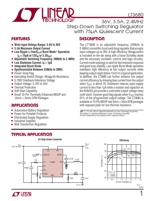
13680faStep-Down Switching Regulatorwith 75µA Quiescent CurrentThe LT ®3680 is an adjustable frequency (200kHz to 2.4MHz) monolithic buck switching regulator that accepts input voltages up to 36V. A high effi ciency 95m switch is included on the die along with a boost Schottky diode and the necessary oscillator, control, and logic circuitry. Current mode topology is used for fast transient response and good loop stability. Low ripple Burst Mode operation maintains high effi ciency at low output currents while keeping output ripple below 15mV in a typical application. In addition, the LT3680 can further enhance low output current effi ciency by drawing bias current from the output when V OUT is above 3V. Shutdown reduces input supply current to less than 1μA while a resistor and capacitor on the RUN/SS pin provide a controlled output voltage ramp (soft-start). A power good fl ag signals when V OUT reaches 91% of the programmed output voltage. The LT3680 is available in 10-Pin MSOP and 3mm × 3mm DFN packages with exposed pads for low thermal resistance.■Automotive Battery Regulation ■ Power for Portable Products ■ Distributed Supply Regulation ■ Industrial Supplies■ Wall Transformer Regulation■Wide Input Voltage Range: 3.6V to 36V ■ 3.5A Maximum Output Current■ Low Ripple (<15mV P-P ) Burst Mode ® Operation:I Q = 75μA at 12V IN to 3.3V OUT■ Adjustable Switching Frequency: 200kHz to 2.4MHz ■ Low Shutdown Current: I Q < 1μA ■ Integrated Boost Diode■ Synchronizable Between 250kHz to 2MHz ■ Power Good Flag■ Saturating Switch Design: 95m On-Resistance ■ 0.790V Feedback Reference Voltage ■ Output Voltage: 0.79V to 30V ■ Thermal Protection ■ Soft-Start Capability■ Small 10-Pin Thermally Enhanced MSOP and (3mm × 3mm) DFN Packages5V Step-Down ConverterV IN 6.3V TO 36VV OUTEffi ciencyBurst Mode is a registered trademark of Linear Technology Corporation. All other trademarks are the property of their respective owners.OUTPUT CURRENT (A)0.550E F F I C I E N C Y (%)7010012 2.53680 G016090801.533.5T YPICAL APPLICATIOND ESCRIPTIONF EATURESA PPLICATIONS23680faELECTRICAL CHARACTERISTICS V IN , RUN/SS Voltage .................................................36V BOOST Pin Voltage ...................................................56V BOOST Pin Above SW Pin .........................................30V FB, RT, V C Voltage .......................................................5V PG, BD, SYNC Voltage . (30V)(Note 1)PARAMETER CONDITIONSMIN TYP MAX UNITSMinimum Input Voltage ●3 3.6V Quiescent Current from V INV RUN/SS = 0.2V 0.010.5μA V BD = 3V, Not Switching ●3065μA V BD = 0, Not Switching120160μA Quiescent Current from BDV RUN/SS = 0.2V 0.010.5μA V BD = 3V, Not Switching●90130μAThe ● denotes the specifi cations which apply over the full operatingtemperature range, otherwise specifi cations are at T A = 25°C. V IN = 10V, V RUN/SS = 10V, V BOOST = 15V, V BD = 3.3V unless otherwise noted. (Note 2)Operating Junction Temperature Range (Note 2)LT3680E .............................................–40°C to 125°C LT3680I..............................................–40°C to 125°C Storage Temperature Range ...................–65°C to 150°C Lead Temperature (Soldering, 10 sec)(MSE Only) .......................................................300°CTOP VIEWDD PACKAGE10-LEAD (3mm s 3mm) PLASTIC DFN1096784531121RT V C FB PG SYNCBD BOOST SW V IN RUN/SSθJA = 45°C/W, θJC = 10°C/WEXPOSED PAD (PIN 11) IS GND, MUST BE SOLDERED TO PCB12345BD BOOST SW V IN RUN/SS109876RT V C FB PG SYNCTOP VIEWMSE PACKAGE10-LEAD PLASTIC MSOP 11θJA = 45°C/W, θJC = 10°C/WEXPOSED PAD (PIN 11) IS GND, MUST BE SOLDERED TO PCBPIN CONFIGURATIONORDER INFORMATIONLEAD FREE FINISH TAPE AND REEL PART MARKING*PACKAGE DESCRIPTIONTEMPERATURE RANGE LT3680EDD#PBF LT3680EDD#TRPBF LCYK 10-Lead (3mm × 3mm) Plastic DFN –40°C to 125°C LT3680IDD#PBF LT3680IDD#TRPBF LCYK 10-Lead (3mm × 3mm) Plastic DFN –40°C to 125°C LT3680EMSE#PBF LT3680EMSE#TRPBF LTCYM 10-Lead Plastic MSOP –40°C to 125°C LT3680IMSE#PBFLT3680IMSE#TRPBFLTCYM10-Lead Plastic MSOP–40°C to 125°CConsult LTC Marketing for parts specifi ed with wider operating temperature ranges. *The temperature grade is identifi ed by a label on the shipping container.Consult LTC Marketing for information on non-standard lead based fi nish parts.For more information on lead free part marking, go to: /leadfree/ For more information on tape and reel specifi cations, go to: /tapeandreel/A BSOLUTE MAXIMUM RATINGSPARAMETER CONDITIONS MIN TYP MAX UNITSV BD = 0, Not Switching15μA Minimum Bias Voltage (BD Pin) 2.73VFeedback Voltage●780775790790800805mVmVFB Pin Bias Current (Note 3)V FB = 0.8V, V C = 0.4V●1040nA FB Voltage Line Regulation4V < V IN < 36V0.0020.01%/V Error Amp g m500μMho Error Amp Gain2000V C Source Current60μA V C Sink Current60μA V C Pin to Switch Current Gain 5.3A/V V C Clamp Voltage 2.0VSwitching Frequency R T = 8.66kR T = 29.4kR T = 187k 2.21.02002.451.12302.71.25260MHzMHzkHzMinimum Switch Off-Time●60150nS Switch Current Limit Duty Cycle = 5% 4.6 5.4 6.0A Switch V CESAT I SW = 3.5A335mV Boost Schottky Reverse Leakage V BOOST = 10V, V BD = 0V0.022μA Minimum Boost Voltage (Note 4)● 1.5 2.0V BOOST Pin Current I SW = 1A3550mA RUN/SS Pin Current V RUN/SS = 2.5V58μA RUN/SS Input Voltage High 2.5V RUN/SS Input Voltage Low0.2V PG Threshold Offset from Feedback Voltage V FB Rising65mV PG Hysteresis10mV PG Leakage V PG = 5V0.11μA PG Sink Current V PG = 0.4V●200800μA SYNC Low Threshold0.5V SYNC High Threshold0.7V SYNC Pin Bias Current V SYNC = 0V0.1μANote 1: Stresses beyond those listed under Absolute Maximum Ratings may cause permanent damage to the device. Exposure to any Absolute Maximum Rating condition for extended periods may affect device reliability and lifetime.Note 2: The LT3680E is guaranteed to meet performance specifi cations from 0°C to 125°C. Specifi cations over the –40°C to 125°C operating temperature range are assured by design, characterization and correlation with statistical process controls. The LT3680I specifi cations are guaranteed over the –40°C to 125°C temperature range.Note 3: Bias current fl ows out of the FB pin.Note 4: This is the minimum voltage across the boost capacitor needed to guarantee full saturation of the switch.The● denotes the specifi cations which apply over the full operating temperature range, otherwise specifi cations are at T A = 25°C. V IN = 10V, V RUN/SS = 10V V BOOST = 15V, V BD = 3.3V unless otherwise noted. (Note 2)ELECTRICAL CHARACTERISTICS33680fa43680faINPUT VOLTAGE (V)S U P P L Y C U R R E N T (μA )153680 G04503051020101301109070253035DUTY CYCLE (%)S W I T C H C U R R E N T L I M I T (A )403680 G084.520603.53.06.05.55.04.080100TEMPERATURE (°C)–50S U P P L Y C U R R E N T (μA )350253680 G05200100–25505040030025015075100150125OUTPUT CURRENT (A)0.550E F F I C I E N C Y (%)7010012 2.53680 G016090801.533.5OUTPUT CURRENT (A)0.550E F F I C I E N C Y (%)7010012 2.53680 G026090801.533.5INPUT VOLTAGE (V)5L O A D C U R R E N T (A )153680 G074.510203.53.05.55.04.02530INPUT VOLTAGE (V)5L O A D C U R R E N T (A )153680 G064.010203.02.55.55.04.53.52530TEMPERATURE (°C)S W I T C H C U R R E N T L I M I T (A )4.04.55.55.03680 G093.53.02.02.56.56.0–5025–255075100150125Effi ciencyEffi ciencyNo Load Supply CurrentMaximum Load CurrentSwitch Current LimitSwitch Current LimitMaximum Load CurrentNo Load Supply CurrentEffi ciencyT A = 25°C unless otherwise noted.OUTPUT CURRENT (A)0.550E F F I C I E N C Y (%)TOTAL POWER LOSS (W)7010012 2.53680 G036090800.51.53.01.02.52.01.533.5T YPICAL PERFORMANCE CHARACTERISTICS53680faBOOST DIODE CURRENT (A)B O O S T D I O D E V F (V )0.81.01.2 2.03680 G180.60.400.5 1.0 1.50.21.4RUN/SS PIN VOLTAGE (V)0S W I T C H C U R R E N T L I M I T (A )1.53680 G16420.512107653 2.533.5FB PIN VOLTAGE (mV)0S W I T C H I N G F R E Q U E N C Y (k H z )800100012006003680 G14600400200400800500100300700900200TEMPERATURE (°C)M I N I M U M S W I T C H O N T I M E (n s )801001203680 G156040200140–5025–255075100150125RUN/SS PIN VOLTAGE (V)R U N /S S P I N C U R R E N T (μA )8101215253680 G17645102030352SWITCH CURRENT (A)B O O S T P I NC U R R E N T (m A )154560751203680 G113090105031245TEMPERATURE (°C)F E E D B A C K V O L T AG E (m V )8003680 G12760840780820–5025–255075100150125TEMPERATURE (°C)F R E Q U E N C Y (M H z )1.001.103680 G130.900.801.200.951.050.851.15–5025–255075100150125SWITCH CURRENT (A)40050070033680 G1030020012451000600V O L T A G E D R O P (m V)Boost Pin CurrentFeedback VoltageSwitching FrequencyFrequency FoldbackMinimum Switch On-TimeSoft-StartRUN/SS Pin CurrentBoost DiodeSwitch Voltage DropT A = 25°C unless otherwise noted.T YPICAL PERFORMANCE CHARACTERISTICS63680faFB PIN ERROR VOLTAGE (mV)–200–50V C P I N C U R R E N T (μA )–200200200503680 G19–40–1001004010–1030–30Error Amp Output CurrentTEMPERATURE (°C)V C V O L T A G E (V )1.502.002.503680 G221.000.50–5025–255075100150125LOAD CURRENT (mA)1I N P U T V O L T A G E (V )3.03.5100003680 G202.52.01010010005.04.54.0110000101001000LOAD CURRENT (mA)I N P U T V O L T A G E (V )5.05.53680 G214.54.06.56.03680 G24I L0.2A/DIVV SW 5V/DIVV OUT 10mV/DIV5μs/DIVV IN = 12V V OUT = 3.3V I LOAD = 10mATEMPERATURE (°C)T H R E S H O L D V O L T A G E (%)8590953680 G238075–5025–2550751001501253680 G25I L0.2A/DIV V SW 5V/DIVV OUT10mV/DIVV IN = 12V V OUT = 3.3V I LOAD = 110mA1μs/DIV3680 G26I L0.5A/DIVV SW 5V/DIVV OUT10mV/DIVV IN = 12V V OUT = 3.3V I LOAD = 1A1μs/DIVMinimum Input VoltageMinimum Input VoltageV C VoltagesPower Good Threshold Switching Waveforms; Transition from Burst Mode to Full FrequencySwitching Waveforms; Full Frequency Continuous OperationSwitching Waveforms; Burst ModeT A = 25°C unless otherwise noted.T YPICAL PERFORMANCE CHARACTERISTICS73680faBD (Pin 1): This pin connects to the anode of the boost Schottky diode. BD also supplies current to the internal regulator.BOOST (Pin 2): This pin is used to provide a drive voltage, higher than the input voltage, to the internal bipolar NPN power switch.SW (Pin 3): The SW pin is the output of the internal power switch. Connect this pin to the inductor, catch diode and boost capacitor.V IN (Pin 4): The V IN pin supplies current to the LT3680’s internal regulator and to the internal power switch. This pin must be locally bypassed.RUN/SS (Pin 5): The RUN/SS pin is used to put the LT3680 in shutdown mode. Tie to ground to shut down the LT3680. Tie to 2.5V or more for normal operation. If the shutdown feature is not used, tie this pin to the V IN pin. RUN/SS also provides a soft-start function; see the Applications Information section.SYNC (Pin 6): This is the external clock synchronization input. Ground this pin for low ripple Burst Mode operation at low output loads. Tie to a clock source for synchroniza-tion. Clock edges should have rise and fall times faster than 1μs. Do not leave pin fl oating. See synchronizing section in Applications Information.PG (Pin 7): The PG pin is the open collector output of an internal comparator. PG remains low until the FB pin is within 9% of the fi nal regulation voltage. PG output is valid when V IN is above 3.6V and RUN/SS is high.FB (Pin 8): The LT3680 regulates the FB pin to 0.790V. Connect the feedback resistor divider tap to this pin.V C (Pin 9): The V C pin is the output of the internal error amplifi er. The voltage on this pin controls the peak switch current. Tie an RC network from this pin to ground to compensate the control loop.RT (Pin 10): Oscillator Resistor Input. Connecting a resistor to ground from this pin sets the switching frequency.Exposed Pad (Pin 11): Ground. The Exposed Pad must be soldered to PCB.+–V OUTB LOCK DIAGRAMP IN FUNCTIONSThe LT3680 is a constant frequency, current mode step-down regulator. An oscillator, with frequency set by RT, enables an RS flip-flop, turning on the internal power switch. An amplifi er and comparator monitor the current fl owing between the V IN and SW pins, turning the switch off when this current reaches a level determined by the voltage at V C. An error amplifier measures the output voltage through an external resistor divider tied to the FB pin and servos the V C pin. If the error amplifi er’s output increases, more current is delivered to the output; if it decreases, less current is delivered. An active clamp on the V C pin provides current limit. The V C pin is also clamped to the voltage on the RUN/SS pin; soft-start is implemented by generating a voltage ramp at the RUN/SS pin using an external resistor and capacitor.An internal regulator provides power to the control circuitry. The bias regulator normally draws power from the V IN pin, but if the BD pin is connected to an external voltage higher than 3V bias power will be drawn from the external source (typically the regulated output voltage). This improves effi ciency. The RUN/SS pin is used to place the LT3680 in shutdown, disconnecting the output and reducing the input current to less than 0.5μA. The switch driver operates from either the input or from the BOOST pin. An external capacitor and diode are used to generate a voltage at the BOOST pin that is higher than the input supply. This allows the driver to fully saturate the internal bipolar NPN power switch for effi cient opera-tion.To further optimize effi ciency, the LT3680 automatically switches to Burst Mode operation in light load situations. Between bursts, all circuitry associated with controlling the output switch is shut down, reducing the input supply current to 75μA in a typical application.The oscillator reduces the LT3680’s operating frequency when the voltage at the FB pin is low. This frequency foldback helps to control the output current during startup and overload.The LT3680 contains a power good comparator which trips when the FB pin is at 91% of its regulated value. The PG output is an open-collector transistor that is off when the output is in regulation, allowing an external resistor to pull the PG pin high. Power good is valid when the LT3680 is enabled and V IN is above 3.6V.OPERATION83680fa93680faFB Resistor NetworkThe output voltage is programmed with a resistor divider between the output and the FB pin. Choose the 1% resis-tors according to:R R V V OUT 120791=⎛⎝⎜⎞⎠⎟.–Reference designators refer to the Block Diagram.Setting the Switching FrequencyThe LT3680 uses a constant frequency PWM architecture that can be programmed to switch from 200kHz to 2.4MHz by using a resistor tied from the RT pin to ground. A table showing the necessary RT value for a desired switching frequency is in Figure 1.SWITCHING FREQUENCY (MHz)R T VALUE (k Ω)0.20.30.40.50.60.70.80.91.01.21.41.61.82.02.22.421514010078.763.453.645.339.23426.722.118.21512.710.79.09Figure 1. Switching Frequency vs. R T ValueOperating Frequency TradeoffsSelection of the operating frequency is a tradeoff between effi ciency, component size, minimum dropout voltage, and maximum input voltage. The advantage of high frequency operation is that smaller inductor and capacitor values may be used. The disadvantages are lower effi ciency, lower maximum input voltage, and higher dropout voltage. The highest acceptable switching frequency (f SW(MAX)) for a given application can be calculated as follows:f V V t V V V SW MAX D OUTON MIN D IN SW ()()=++()–where V IN is the typical input voltage, V OUT is the output voltage, V D is the catch diode drop (~0.5V) and V SW is the internal switch drop (~0.5V at max load). This equation shows that slower switching frequency is necessary to safely accommodate high V IN /V OUT ratio. Also, as shown in the next section, lower frequency allows a lower dropout voltage. The reason input voltage range depends on the switching frequency is because the LT3680 switch has fi nite minimum on and off times. The switch can turn on for a minimum of ~150ns and turn off for a minimum of ~150ns. Typical minimum on time at 25°C is 80ns. This means that the minimum and maximum duty cycles are:DC f t DC f t MIN SW ON MIN MAX SW OFF MIN ==()()1–where f SW is the switching frequency, the t ON(MIN) is the minimum switch on time (~150ns), and the t OFF(MIN) is the minimum switch off time (~150ns). These equations show that duty cycle range increases when switching frequency is decreased.A good choice of switching frequency should allow ad-equate input voltage range (see next section) and keep the inductor and capacitor values small. Input Voltage RangeThe maximum input voltage for LT3680 applications depends on switching frequency and Absolute Maxi-mum Ratings of the V IN and BOOST pins (36V and 56V respectively).While the output is in start-up, short-circuit, or other overload conditions, the switching frequency should be chosen according to the following equation:V V V f t V V IN MAX OUT DSW ON MIN D SW()()=++–where V IN(MAX) is the maximum operating input voltage, V OUT is the output voltage, V D is the catch diode drop (~0.5V), V SW is the internal switch drop (~0.5V at max load), f SW is the switching frequency (set by R T ), and t ON(MIN) is the minimum switch on time (~100ns). Note that a higher switching frequency will depress the maximumAPPLICATIONS INFORMATION103680faoperating input voltage. Conversely, a lower switching frequency will be necessary to achieve safe operation at high input voltages.If the output is in regulation and no short-circuit, start-up, or overload events are expected, then input voltage transients of up to 36V are acceptable regardless of the switching frequency. In this mode, the LT3680 may enter pulse skipping operation where some switching pulses are skipped to maintain output regulation. In this mode the output voltage ripple and inductor current ripple will be higher than in normal operation.The minimum input voltage is determined by either the LT3680’s minimum operating voltage of ~3.6V or by its maximum duty cycle (see equation in previous section). The minimum input voltage due to duty cycle is:V V V f t V V IN MIN OUT DSW OFF MIN D SW()()=++1––where V IN(MIN) is the minimum input voltage, and t OFF(MIN)is the minimum switch off time (150ns). Note that higher switching frequency will increase the minimum input voltage. If a lower dropout voltage is desired, a lower switching frequency should be used.Inductor SelectionFor a given input and output voltage, the inductor value and switching frequency will determine the ripple current. The ripple current ΔI L increases with higher V IN or V OUT and decreases with higher inductance and faster switch-ing frequency. A reasonable starting point for selecting the ripple current is: ΔI L = 0.4(I OUT(MAX))where I OUT(MAX) is the maximum output load current. To guarantee suffi cient output current, peak inductor current must be lower than the LT3680’s switch current limit (I LIM ). The peak inductor current is: I L(PEAK) = I OUT(MAX) + ΔI L /2where I L(PEAK) is the peak inductor current, I OUT(MAX) is the maximum output load current, and ΔI L is the inductorripple current. The LT3680’s switch current limit (I LIM ) is 5.5A at low duty cycles and decreases linearly to 4.5A at DC = 0.8. The maximum output current is a function of the inductor ripple current: I OUT(MAX) = I LIM – ΔI L /2Be sure to pick an inductor ripple current that provides suffi cient maximum output current (I OUT(MAX)).The largest inductor ripple current occurs at the highest V IN . To guarantee that the ripple current stays below the specifi ed maximum, the inductor value should be chosen according to the following equation:L V V f I V V V OUT D SW L OUT D IN MAX =+⎛⎝⎜⎞⎠⎟+⎛⎝⎜⎞⎠Δ1–()⎟where V D is the voltage drop of the catch diode (~0.4V), V IN(MAX) is the maximum input voltage, V OUT is the output voltage, f SW is the switching frequency (set by RT), and L is in the inductor value.The inductor’s RMS current rating must be greater than the maximum load current and its saturation current should be about 30% higher. For robust operation in fault conditions (start-up or short circuit) and high input voltage (>30V), the saturation current should be above 5A. To keep the effi ciency high, the series resistance (DCR) should be less than 0.1, and the core material should be intended for high frequency applications. Table 1 lists several vendors and suitable types.Table 1. Inductor VendorsVENDOR URLPART SERIES TYPE Murata LQH55D Open TDK SLF10145Shielded Toko D75C D75F Shielded Open SumidaCDRH74CR75CDRH8D43Shielded Open Shielded N EC MPLC073MPBI0755Shielded ShieldedAPPLICATIONS INFORMATIONOf course, such a simple design guide will not always re-sult in the optimum inductor for your application. A larger value inductor provides a slightly higher maximum load current and will reduce the output voltage ripple. If your load is lower than 3.5A, then you can decrease the value of the inductor and operate with higher ripple current. This allows you to use a physically smaller inductor, or one with a lower DCR resulting in higher effi ciency. There are several graphs in the Typical Performance Characteristics section of this data sheet that show the maximum load current as a function of input voltage and inductor value for several popular output voltages. Low inductance may result in discontinuous mode operation, which is okay but further reduces maximum load current. For details of maximum output current and discontinuous mode opera-tion, see Linear Technology Application Note 44. Finally, for duty cycles greater than 50% (V OUT/V IN > 0.5), there is a minimum inductance required to avoid subharmonic oscillations. See AN19.Input CapacitorBypass the input of the LT3680 circuit with a ceramic capacitor of X7R or X5R type. Y5V types have poor performance over temperature and applied voltage, and should not be used. A 10μF to 22μF ceramic capacitor is adequate to bypass the LT3680 and will easily handle the ripple current. Note that larger input capacitance is required when a lower switching frequency is used. If the input power source has high impedance, or there is signifi cant inductance due to long wires or cables, additional bulk capacitance may be necessary. This can be provided with a lower performance electrolytic capacitor.Step-down regulators draw current from the input sup-ply in pulses with very fast rise and fall times. The input capacitor is required to reduce the resulting voltage ripple at the LT3680 and to force this very high frequency switching current into a tight local loop, minimizing EMI.A 10μF capacitor is capable of this task, but only if it is placed close to the LT3680 and the catch diode (see the PCB Layout section). A second precaution regarding the ceramic input capacitor concerns the maximum input voltage rating of the LT3680. A ceramic input capacitor combined with trace or cable inductance forms a high quality (under damped) tank circuit. If the LT3680 circuit is plugged into a live supply, the input voltage can ring to twice its nominal value, possibly exceeding the LT3680’s voltage rating. This situation is easily avoided (see the Hot Plugging Safety section).For space sensitive applications, a 4.7μF ceramic capaci-tor can be used for local bypassing of the LT3680 input. However, the lower input capacitance will result in in-creased input current ripple and input voltage ripple, and may couple noise into other circuitry. Also, the increased voltage ripple will raise the minimum operating voltage of the LT3680 to ~3.7V.Output Capacitor and Output RippleThe output capacitor has two essential functions. Along with the inductor, it fi lters the square wave generated by the LT3680 to produce the DC output. In this role it determines the output ripple, and low impedance at the switching frequency is important. The second function is to store energy in order to satisfy transient loads and stabilize the LT3680’s control loop. Ceramic capacitors have very low equivalent series resistance (ESR) and provide the best ripple performance. A good starting value is:CV fOUTOUT SW=100where f SW is in MHz, and C OUT is the recommended output capacitance in μF. Use X5R or X7R types. This choice will provide low output ripple and good transient response. Transient performance can be improved with a higher value capacitor if the compensation network is also adjusted to maintain the loop bandwidth. A lower value of output capacitor can be used to save space and cost but transient performance will suffer. See the Fre-quency Compensation section to choose an appropriate compensation network.When choosing a capacitor, look carefully through the data sheet to fi nd out what the actual capacitance is under operating conditions (applied voltage and temperature).A physically larger capacitor, or one with a higher volt-age rating, may be required. High performance tantalum or electrolytic capacitors can be used for the outputAPPLICATIONS INFORMATIONcapacitor. Low ESR is important, so choose one that is intended for use in switching regulators. The ESR should be specifi ed by the supplier, and should be 0.05 or less. Such a capacitor will be larger than a ceramic capacitor and will have a larger capacitance, because the capacitor must be large to achieve low ESR. Table 2 lists several capacitor vendors.Catch DiodeThe catch diode conducts current only during switch off time. Average forward current in normal operation can be calculated from:I D(AVG) = I OUT (V IN – V OUT )/V INwhere I OUT is the output load current. The only reason to consider a diode with a larger current rating than necessary for nominal operation is for the worst-case condition of shorted output. The diode current will then increase to the typical peak switch current. Peak reverse voltage is equal to the regulator input voltage. Use a schottky diode with a reverse voltage rating greater than the input voltage. Table 3 lists several Schottky diodes and their manufacturers.Table 3. Diode VendorsPART NUMBER V R (V)I AVE (A)V F AT 3A (mV)On Semiconductor MBRA340403500Diodes Inc.PDS340B340A B340LA404040333500500450Ceramic CapacitorsCeramic capacitors are small, robust and have very low ESR. However, ceramic capacitors can cause problems when used with the LT3680 due to their piezoelectric nature. When in Burst Mode operation, the LT3680’s switching frequency depends on the load current, and at very light loads the LT3680 can excite the ceramic capaci-tor at audio frequencies, generating audible noise. Since the LT3680 operates at a lower current limit during Burst Mode operation, the noise is nearly silent to a casual ear. If this is unacceptable, use a high performance tantalum or electrolytic capacitor at the output.VENDOR PHONE URLPART SERIES COMMANDSPanasonic(714) 373-7366Ceramic,Polymer,TantalumEEF Series Kemet (864) Ceramic,Tantalum T494, T495Sanyo(408) 749-9714Ceramic,Polymer,TantalumPOSCAP Murata (408) 436-1300 Ceramic AVX Ceramic,Tantalum TPS Series Taiyo Yuden(864) CeramicTable 2. Capacitor VendorsAPPLICATIONS INFORMATION。
天成TC3838RGB-3CSA-TX1818H内置IC12v规格书
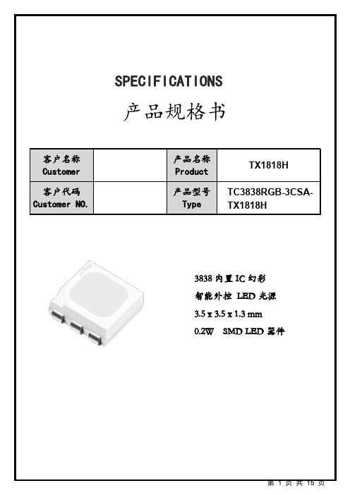
目录1、产品概述 (3)2、主要应用 (3)3、特征说明 (3)4、产品尺寸 (4)5、产品命名规则 (4)6、引脚功能 (5)7、RGB光电特性 (5)8、绝对最大值 (6)9、IC电气参数 (6)10、开关特性 (6)11、数据传输时间 (7)12、时序波形图 (7)13、数据传输方式 (8)14、24bit数据结构 (8)15、典型应用电路 (8)16、光电特性曲线 (9)17、包装 (10)18、可靠性测试 (11)19、焊接说明 (112)20、注意事项 (113)1.Description(产品描述)TX1818H是一个集控制电路与发光电路于一体的智能外控LED光源。
其外型与一个3838LED灯珠相同,每个元件即为一个像素点。
像素点内部包含了智能数字接口数据锁存信号整形放大驱动电路,电源稳压电路,内置恒流电路,高精度RC振荡器,输出驱动采用专利PWM技术,有效保证了像素点内光的颜色高一致性。
数据协议采用单极性归零码的通讯方式,像素点在上电复位以后,DIN端接受从控制器传输过来的数据,首先送过来的24bit数据被第一个像素点提取后,送到像素点内部的数据锁存器,剩余的数据经过内部整形处理电路整形放大后通过DO端口开始转发输出给下一个级联的像素点,每经过一个像素点的传输,信号减少24bit。
LED具有低电压驱动,环保节能,亮度高,散射角度大,一致性好,超低功率,超长寿命等优点。
将控制电路集成于LED上面,电路变得更加简单,体积小,安装更加简便。
2.Applications(主要应用)LED全彩发光字灯串,LED全彩模组,LED幻彩软硬灯条,LED护栏管,LED外观/情景照明。
LED点光源,LED像素屏,LED异形屏,各种电子产品,电器设备跑马灯。
3.Features(特征说明)采用高压功率CMOS工艺致性高;内置高精度和高稳定性振荡器;内置上电复位和掉电复位电路,上电不亮灯;灰度调节电路(256级灰度可调);默认输出恒流值9mA,便于降低灯珠功耗;数据整形:接受完本单元数据自动将后续数据整形输出;数据传输频率可达800Kbps。
CS6583 LED电源PDF规格书
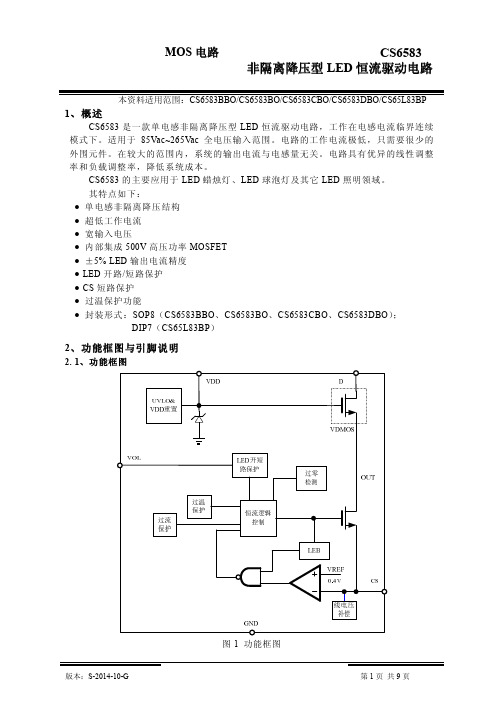
M OS 电 路
CS6583
2. 4、引脚说明与结构原理图 引脚 1 符 号 功 地 能 属性 P 结 构 原 理 图
GND
2
VOL
开路保护电压调节端,接电 阻到地
I
3
NC
无连接,悬空
4
VDD
电源
P
5、6
D
内部高压功率管漏极
O
7 ( 8)
CS
电流采样端
I
3、 电特性
3. 1 、 极限参数 除非特别说明, T amb = 25℃ 参 数 名 称 电源电压 功率管漏端 低压模拟端口( CS , ZCD ) 功耗 热阻 工作温度 工作结温 储存温度 ESD ( HBM 模型) P DMAX θ JA TOP TJ TSTG 符 号 VDD VDRAIN 额 定 值 -0.3~21 -0.3~500 -0.3~7 0.45 ( SOP8 ) 0.9 ( DIP7 ) 145 ( SOP8 ) 80 ( DIP7 ) -40~105 -45~150 -65~150 4 单 位 V V V W W ℃ /W ℃ /W ℃ ℃ ℃ kV
MOS 电路
CS6583 非隔离降压型 LED 恒流驱动电路
本资料适用范围:CS6583BBO/CS6583BO/CS6583CBO/CS6583DBO/CS65L83BP
1、概述
CS6583 是一款单电感非隔离降压型 LED 恒流驱动电路,工作在电感电流临界连续 模式下。适用于 85Vac~265Vac 全电压输入范围。电路的工作电流极低 ,只需要很少的 外围元件。在较大的范围内,系统的输出电流与电感量无关。电路具有优异的线性调整 率和负载调整率,降低系统成本。 CS6583 的主要应用于 LED 蜡烛灯、 LED 球泡灯及其它 LED 照明领域。 其特点如下: ● 单电感非隔离降压结构 ● 超低工作电流 ● 宽输入电压 ● 内部集成 500V 高压功率 MOSFET ● ± 5% LED 输出电流精度 ● LED 开路 / 短路保护 ● CS 短路保护 ● 过温保护功能 ● 封装形式: SOP8 ( CS6583BBO 、 CS6583BO 、 CS6583CBO 、 CS6583DBO ) ; DIP7 ( CS65L83BP )
LT1460CCMS8-2.5#PBF资料
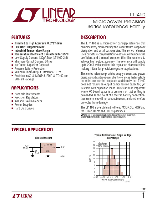
UW U PACKAGE/ORDER I FOR ATIO
ORDER PART NUMBER
SOT- 23 Package
U APPLICATIO S
■ Handheld Instruments ■ Precision Regulators ■ A/D and D/A Converters ■ Power Supplies ■ Hard Disk Drives
TYPICAL APPLICATIO
元器件交易网
FEATURES
■ Trimmed to High Accuracy: 0.075% Max ■ Low Drift: 10ppm/°C Max ■ Industrial Temperature Range ■ Temperature Coefficient Guaranteed to 125°C ■ Low Supply Current: 130µA Max (LT1460-2.5) ■ Minimum Output Current: 20mA ■ No Output Capacitor Required ■ Reverse Battery Protection ■ Minimum Input/Output Differential: 0.9V ■ Available in S0-8, MSOP-8, PDIP-8, TO-92 and
This series reference provides supply current and power dissipation advantages over shunt references that must idle the entire load current to operate. Additionally, the LT1460 does not require an output compensation capacitor, yet is stable with capacitive loads. This feature is important where PC board space is a premium or fast settling is demanded. In the event of a reverse battery connection, these references will not conduct current, and are therefore protected from damage.
CS1258系列AFE用户手册v02

CS1258 芯片用户手册带24bits ADC 和BIM 的高性能AFEREV0.2 通讯地址:深圳市南山区蛇口南海大道1079 号花园城数码大厦A座9楼邮政编码:518067公司电话:+(86 755)86169257传真:+(86 755)86169057公司网站:CS1258 芯片用户手册版本历史修改记录日期0.1 预览版本2016/3/15 0.2 .更新了电气特性2016/3/29.更新了典型应用图.更新了封装图目录版本历史 (2)目录 (3)图目录 (5)表目录 (5)1 简介 (6)1.1 主要特性 (6)1.2 应用场合 (6)1.3 功能说明 (6)1.4 极限值 (8)1.5 电气特性 (9)1.6 可靠性指标 (10)1.7 产品型号及引脚 (11)1.8 典型应用电路 (12)2 功能寄存器说明 (13)2.1 功能寄存器列表 (13)2.2 功能寄存器说明 (13)2.2.1 SYS —系统配置寄存器 (13)2.2.2 ADC0— ADC 配置寄存器 (14)2.2.3 ADC1— ADC 配置寄存器1 (14)2.2.4 ADC2— ADC 配置寄存器2 (15)2.2.5 ADC3— ADC 配置寄存器3 (15)2.2.6 ADC4— ADC 配置寄存器4 (16)2.2.7 ADC5— ADC 配置寄存器5 (16)2.2.8 BIM0— BIM 配置寄存器0 (17)2.2.9 BIM1— BIM 配置寄存器 (17)2.2.10 ADO— ADC 转换数据寄存器 (18)2.2.11 ADS— ADC 转换数据读取标准寄存器 (18)3 功能描述 (19)3.1 输入选择 (19)3.2 输入电平移位器 (19)3.3 IDAC1/IDAC0 和输入通道 (20)3.4 PGA 和ADC (21)3.5 数字滤波器 (23)3.5.1 频率响应 (23)3.5.2 建立时间 (23)3.6 人体阻抗测量 (25)3.6.1 正弦信号发生器 (25)3.6.2 激励电极及测量电极 (26)3.6.3 整流 (26)3.6.4 阻抗校准 (27)3.7 参考电压源 (28)3.8 内部时钟源 (28)3.9 温度传感器 (28)3.10 测量模式及其切换 (28)3.11 多种工作模式 (29)3.12 复位和断电(POR&power down) (30)4 转换有效位 (31)5 典型特性 (32)5.1 ADC 典型特性 (32)5.2 LDO/VREF 典型特性 (32)5.3 内部时钟典型特性 (32)5.4 IDAC 典型特性 (32)5.5 BIM 典型特性 (32)6 三线串行通讯接口 (37)6.1.1 读时序 (38)6.1.2 写时序 (38)7 封装 (40)图目录图 1.1 CS1258 原理框图 (7)图 1.2 CS1258 引脚图 (11)图 1.3 CS1258 典型应用电路 (12)图 3.1 模拟输入结构图 (19)图 3.2 电平移位模块 (20)图 3.3 IDAC1/IDAC0 结构及与输入通道关系 (20)图 3.4 PGA 和ADC 结构图 (21)图 3.5 COMB 滤波器的频率响应特性(Fs=331Hz,DR=10Hz,3 阶COMB) (23)图 3.6 COMB 建立过程 (24)图 3.7 BIM 模块结构图 (25)图 3.8 CS1258 低功耗工作示意图 (29)图 5.1 内部时钟全电压全温度范围的典型特性 (32)图 5.2 FWR 模式下220 欧姆纯电阻网络的测试结果 (33)图 5.3 FWR 模式下1000 欧姆纯电阻网络的测试结果 (33)图 5.4 FWR 模式下1958 欧姆纯电阻网络的测试结果 (34)图 5.5 FWR+MIX 模式510ohm+470pF 并联网络的阻抗绝对值测试结果 (34)图 5.6 FWR+MIX 模式510ohm+470pF 并联网络的相位角测试结果 (35)图 5.7 FWR+MIX 模式1018Ohm+10nF 并联网络的阻抗绝对值测试结果 (35)图 5.8 FWR+MIX 模式1018Ohm+10nF 并联网络的相位角测试结果 (36)图 6.1 读操作时序1(读AD 值) (38)图 6.2 读操作时序2(除AD 值之外的寄存器) (38)图 6.3 写操作时序 (39)图7.1 芯片LQFP32 封装尺寸信息(天水) (40)表目录表 1.1 CS1258 极限值 (8)表 1.2 CS1258 电气特性 (9)表 1.3 CS1258 引脚说明 (11)表 2.1 功能寄存器列表 (13)表 2.2 SYS 寄存器说明 (13)表 2.3 ADC0 寄存器说明 (14)表 2.4 ADC1 寄存器说明 (14)表 2.5 ADC2 寄存器说明 (15)表 2.6 ADC3 寄存器说明 (15)表 2.7 ADC4 寄存器说明 (16)表 2.8 ADC5 寄存器说明 (16)表 2.9 BIM0 寄存器说明 (17)表 2.10 BIM1 寄存器说明 (17)表 4.1 ADC 信号链不同GAIN 及DR 下的有效位(ENOB)1) (31)表 6.1 串口通讯命令列表 (37)表 6.2 三线串行通讯接口时序表 (39)版权所有,侵权必究芯海科技(深圳)股份有限公司第 5 页,共40 页1 简介1.1 主要特性◆输入●支持单端输入●支持组成多个差分输入对●支持输入电平移位功能◆PGA●1/2/4/8/16/32/64/128 倍可选增益●高达100Mohm 的等效输入阻抗◆BIM●支持4/6/8 电极测量●支持5K/10K/25K/50K/100K/250KHz 多档频率测量●支持阻抗绝对值和相角测量◆ADC●24 bit 分辨率●输出速率10~1280Hz 8 档可选◆有效位● 2.35V 参考、40Hz 速率、128 倍增益下19.5bits 有效位◆LDO 及内部参考电压●自带LDO,输出2.35/2.45/2.8/3.0V 可选,精度±1%●自带低漂移基准,内部参考电压2.048V 可选,精度±1%◆支持性能、普通、低功耗、休眠模式◆支持电压测量、温度测量、BIM 测量及手动测量模式,单命令切换◆低漂移片上时钟◆三线串行通讯1.2 应用场合桥式传感器四角平衡称重压力检测人体阻抗分析交流测脂1.3 功能说明CS1258 原理框图如图1 所示。
CS8441YN8;中文规格书,Datasheet资料
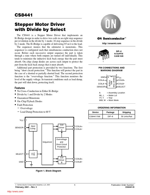
CS8441Stepper Motor Driver with Divide by SelectThe CS8441 is a Stepper Motor Driver that implements an H–Bridge design in order to drive two coils in an eight step sequence per revolution in the divide by 1 mode; 16 step sequence in the divide by 2 mode. The H–Bridge is capable of delivering 85 mA to the load.The sequencer insures that the odometer is monotonic. This sequencer is configured such that simultaneous conduction does not occur. Before each successive output sequence the part is taken through a state where both outputs are turned off individually. This tends to minimize the inductive kick back energy that the part must absorb. On–chip clamp diodes are across each output to protect the part from the kick back energy that it must absorb.Additional part protection is provided by two functions. The first being “short circuit protection.” This function will protect the part in the case of a shorted or partially shorted load. The second protection function is the “overvoltage function.” This function monitors the level of the supply voltage. In transient conditions such as load dump,the part will shut down, protecting itself.Features•No Cross–Conduction in Either H–Bridge •Divide by 1 and Divide by 2 Modes •Guaranteed Monotonic •On–Chip Flyback Diodes •Fault Protection –Overvoltage–Load Dump Protection to 60 VSENSORV CCGNDSELECTCOILA+COILA–COILB+COILB–Figure 1. Block DiagramA = Assembly Location WL, L = Wafer Lot YY , Y = YearWW, W= Work WeekPIN CONNECTIONS AND MARKING DIAGRAMDIP–8N SUFFIX CASE 62618CS8441YN8AWL YYWWV CC COILB+COILB–SELECTGND COILA+COILA–SENSOR 1Device Package Shipping ORDERING INFORMATIONCS8441YN8DIP–850 Units/RailABSOLUTE MAXIMUM RATINGS*2.10 second maximum.*The maximum package power dissipation must be observed.ELECTRICAL CHARACTERISTICS (–40°C ≤ T A≤ 125°C, 6.5 V ≤ V CC≤ 15.5 V; unless otherwise stated. All voltageshall be referenced to GND unless otherwise noted. Overvoltage shutdown of coils occurs when V CC > 16 V.)Characteristic Test Conditions Min Typ Max UnitCoil Output Drivers3.Voltage across the coils shall be measured at the specific voltages, but shall also be within linearly interpolated limits.ELECTRICAL CHARACTERISTICS (continued) (–40°C ≤ T A≤ 125°C, 6.5 V ≤ V CC≤ 15.5 V; unless otherwise stated. All voltage shall be referenced to GND unless otherwise noted. Overvoltage shutdown of coils occurs when V> 16 V.)Short Circuit ProtectionPACKAGE PIN DESCRIPTIONCIRCUIT OPERATIONSPEED SENSOR INPUTSENSOR is a PNP comparator input which accepts a sine wave or a square wave input. This input is protected from excursions above V CC as well as any below ground, as long as the current is limited to 1.5 mA. It has an active clamp set to zero volts to prevent negative input voltages from disrupting normal operation. The sensor input can withstand 150 V DC as long as the input current is limited to 1.5 mA max. using a series resistor of 100 kΩ.COIL DRIVER OUTPUTS Simultaneously energizing the source and sink on either leg is not permitted, i.e. Q1 & Q2 or Q3 & Q4 cannot be energized simultaneously.Circuit function is not affected by inductive transients due to coil loads as specified in the Transition States section. The transition states occur as indicated in Table 1 without any intermediate states permitted.The polarity definition for the coil driver outputs is as follows:DIVIDER SELECT INPUTThe speed sensor input frequency is divided by one or divided by two by connecting the divider select input, (Pin 5) as follows:Logic 0 = divide by 2.Logic 1 = divide by 1.Figure 2. Coil Driver Output01234567012345670State #SSICoil ACoil BFigure 3. Divide by 1 (8 Step Mode), SELECT = 1State #SSICoil ACoil BFigure 4. Divide by 2 (16 Step Mode), SELECT = 0IGNCOIL A210 ±12 ΩCOIL B210 ±12 ΩFigure 5. Odometer Application DiagramPACKAGE DIMENSIONSDIP–8N SUFFIX CASE 626–05ISSUE LNOTES:1.DIMENSION L TO CENTER OF LEAD WHEN FORMED PARALLEL.2.PACKAGE CONTOUR OPTIONAL (ROUND OR SQUARE CORNERS).3.DIMENSIONING AND TOLERANCING PER ANSI Y14.5M, 1982.DIM MIN MAX MIN MAX INCHESMILLIMETERS A 9.4010.160.3700.400B 6.10 6.600.2400.260C 3.94 4.450.1550.175D 0.380.510.0150.020F 1.02 1.780.0400.070G 2.54 BSC 0.100 BSC H 0.76 1.270.0300.050J 0.200.300.0080.012K 2.92 3.430.1150.135L 7.62 BSC 0.300 BSC M ---10 ---10 N0.76 1.010.0300.040__PACKAGE THERMAL DATANotesh ON Semiconductor and are trademarks of Semiconductor Components Industries, LLC (SCILLC). SCILLC reserves the right to make changeswithout further notice to any products herein. SCILLC makes no warranty, representation or guarantee regarding the suitability of its products for any particularpurpose, nor does SCILLC assume any liability arising out of the application or use of any product or circuit, and specifically disclaims any and all liability,including without limitation special, consequential or incidental damages. “Typical” parameters which may be provided in SCILLC data sheets and/orspecifications can and do vary in different applications and actual performance may vary over time. All operating parameters, including “Typicals” must bevalidated for each customer application by customer’s technical experts. SCILLC does not convey any license under its patent rights nor the rights of others.SCILLC products are not designed, intended, or authorized for use as components in systems intended for surgical implant into the body, or other applicationsintended to support or sustain life, or for any other application in which the failure of the SCILLC product could create a situation where personal injury ordeath may occur. Should Buyer purchase or use SCILLC products for any such unintended or unauthorized application, Buyer shall indemnify and holdSCILLC and its officers, employees, subsidiaries, affiliates, and distributors harmless against all claims, costs, damages, and expenses, and reasonableattorney fees arising out of, directly or indirectly, any claim of personal injury or death associated with such unintended or unauthorized use, even if such claimalleges that SCILLC was negligent regarding the design or manufacture of the part. SCILLC is an Equal Opportunity/Affirmative Action Employer.PUBLICATION ORDERING INFORMATIONCENTRAL/SOUTH AMERICA:Spanish Phone:303–308–7143 (Mon–Fri 8:00am to 5:00pm MST)Email:ONlit–spanish@ASIA/PACIFIC: LDC for ON Semiconductor – Asia SupportPhone:303–675–2121 (Tue–Fri 9:00am to 1:00pm, Hong Kong Time)Toll Free from Hong Kong & Singapore:001–800–4422–3781Email: ONlit–asia@JAPAN: ON Semiconductor, Japan Customer Focus Center4–32–1 Nishi–Gotanda, Shinagawa–ku, Tokyo, Japan 141–0031Phone: 81–3–5740–2745Email: r14525@分销商库存信息: ONSEMICS8441YN8。
cherry semiconductor CS8128 数据手册
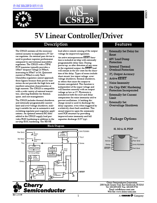
5V Linear Controller/DriverDescriptionNote 1: Dependent on characteristics of external transistor.Power Dissipation.............................................................................................................................................Internally Limited Input Voltage..................................................................................................................................................................–0.3V, 26V Transient Input Voltage............................................................................................................................................................60V Output Current...............................................................................................................................................Externally Limited ESD Susceptibility (Human Body Model)..............................................................................................................................2kV Junction Temperature............................................................................................................................................–45°C to 150°C Storage Temperature..............................................................................................................................................–55°C to 150°C Lead Temperature SolderingWave Solder (through hole styles only).....................................................................................10 sec. max, 260°C peak Reflow (SMD styles only)......................................................................................60 sec. max above 183°C, 230°C peakC S 8128Typical Performance Characteristics (per Test Circuit)54.95JUNCTION TEMPERATURE (°C)V O U T (V )RESET OUTPUT CURRENT (mA)R E S E T O U T P U T V O L T A G E (m V )V IN (V)I Q (m A )I Q vs. V INTemperature Performance of V OUTV IN (V)V O U T(V )I OUT (Amps)D R O P O U T V O L T A GE (m V )I OUT (Amps)L O A D R E G U L A T I O N (m V )Load Regulation vs. I OUTDropout Voltage vs. I OUTV OUT vs. V INI OUT (Amps)L I N E R E G U L A T I O N (m V )I OUT (Amps)I Q (m A )FREQUENCY (Hz)V I N / V O U T (d B )Ripple RejectionI Q vs. I OUTLine Regulation vs. I OUTThe CS8128 function is very precise, has hysteresis on both the and Delay comparators, a latching Delay capacitor discharge circuit, and operation down to 1V.The reset circuit output is an open collector type with ON and OFF parameters as specified. The reset output NPN transistor is controlled by the Low Voltage Inhibit and Reset Delay circuits (see Block Diagram).This circuit monitors output voltage, and when output voltage is below V RTL , causes the reset output transistor to be in the ON (saturation) state. When the output voltage is above V RTH , this circuit permits the reset output transistor to go into the OFF state if allowed by the reset Delay cir-cuit.This circuit provides a programmable (by external capaci-tor) delay on the output lead. The Delay lead pro-vides source current to the external delay capacitor only when the Low Voltage Inhibit circuit indicates that output voltage is above V RTH . Otherwise, the Delay lead sinks current to ground (used to discharge the Delay capacitor).The discharge current is latched ON when the output volt-age falls below V RTL . The Delay capacitor is fully dis-charged anytime the output voltage falls out of regulation,even for a short period of time. This feature ensures a con-trolled pulse is generated following the detection of an error condition. The circuit allows the out-put transistor to go to the OFF (open) state only when the voltage on the Delay lead is higher than V DTC .RESET RESET RESET RESET Delay CircuitLow Voltage Inhibit CircuitRESET RESETC S 8128RESET Circuit Functional DescriptionApplication InformationThe CS8128 includes an over voltage shutdown circuit which is activated by connecting the SHUTDOWN lead to the input. Shutdown typically occurs at 36V. Grounding the SHUTDOWN lead disables this function. With the overvoltage shutdown disabled, the CS8128 will continue to regulate during an overvoltage condition.The CS8128 includes a thermal shutdown circuit that dis-ables the output when junction temperature exceeds approximately 180˚C. This is a self-protection featuredesigned to protect the CS8128. The thermal shutdown cir-cuit does not monitor the temperature of the pass transis-tor, which will probably be much hotter. To optimize ther-mal shutdown, board design should minimize the differ-ence in temperature of the CS8128 and the pass device.External Pass Device - Select a pass device that will deliv-er the desired output current, withstand the maximum expected input voltage, and dissipate the resulting power.The CS8128 is compatible with a wide variety of Bipolar and FET pass transistors.Output Capacitor - An output capacitor is required for sta-bility in most applications. Though a 10µF capacitor should be sufficient, regulator stability is dependent on the characteristics of the pass transistor. Capacitor effective series resistance (ESR) also factors in system stability. Some bench work may be required to determine the capacitor characteristics required for use in a particular application.BIAS Resistor - This resistor provides bias current for the CS8128 output stage, and prevents the pass device from“leaking”. It also speeds the turn-off of the pass device during an overvoltage transient. For proper operation over temperature, the recommended value is 560Ω, although it may be increased or decreased for a particular application.R OUT Resistor - This resistor controls the drive current available to the pass transistor. It also determines regula-tor start-up current and short circuit current limit. Forbipolar pass transistors, it can be selected by use of the fol-lowing formulae:R OUT =x ßQ1*** ***βQ1= Pass transistor minimum β@ maximum output current.Typical start-up current and current limit can be calculat-ed as follows:I START ≈+ 5mA I Limit ≈x ßQ1@ Current LimitFor example, if the minimum input voltage is 6V, maxi-mum output current is 1Amp, and minimum transistor β@ 1Amp is 60, then R OUT can be calculated as follows:R OUT ≈x 60 = 300ΩI Start ≈+ 5mA = 18.3mAWith V IN = 14V, and a pass transistor βof 40 @ current limit:I Limit ≈x 40 = 1.7Amps 14V – 1V300Ω4V 300Ω6V – 1V1Amp V IN – 1VR OUT4VR OUTV IN(min)– 1VI OUT(max)External Component SelectionThermal ShutdownOvervoltage ShutdownPart Number Description CS8128YN88 Lead PDIPCS8128YD88 Lead SO NarrowCS8128YDR88 Lead SO Narrow (tape & reel)DLead Count Metric EnglishMax Min Max Min 8L PDIP10.169.02.400.3558L SO Narrow5.00 4.80.197.189Thermal Data 8 Lead 8 Lead PDIP SO Narrow R ΘJC typ 5245˚C/WR ΘJAtyp100165˚C/WOrdering InformationC S 8128Cherry Semiconductor Corporation reserves the right to make changes to the specifications without notice. Please contact Cherry Semiconductor Corporation for the latest available information.。
BS1363 中文版
注 1:此应用可能为以下中的一种:
a)有一个双重且足够大的绝缘材料制成的罩壳,用相当于强化绝缘的绝缘层将所有金属零件(除
了小部件,例如与带电零件绝缘的面板、螺丝和铆钉)罩住。此应用称为绝缘包装等级 II。
○C BSI
BS 1363-1:1995
9
b)除了使用强化绝缘的部件,有一足够大的金属罩壳、使用双重绝缘的装置(因为两种绝缘是不
为检查所示产品的设计是否符合相关标准的要求而对型式试验样品进行的试验或一系列试验。
3.13 型式试验样品
为进行型式试验而由生产商或责任销售商提交的由一个或多个相似部件或试样组成的样品。
3.14 插头的可触及外露表面
当插头与相应的插头完全契合时,能被 BS 3042:1998 的试验探针 B 触及的所有表面。
3.19 指示灯(信号灯)
○C BSI 2003 年 10 月 9 号
-7-
BS 1363-1:1995
8
用发光表示插头带电的一种灯。
3.20 弹性材料
当移开变形负荷时有固定能力恢复或真正恢复原形的材料。
3.21 爬电距离
两个可导电的零件之间、沿绝缘材料表面的最小距离。
3.22 空气间隙
两可导电零件间在空气中的最小距离。
3.9 夹紧型(无螺纹)接线端
不使用螺丝,通过将软线的导线夹紧于两金属表面之间进行连接的一种接线端。
3.10 接线头
使用专业工具对相应软线和插头的导电部件进行电气连接(如焊接、锻接或压接)的一种装置。
3.11 熔断器架
设计用于装载、保持、遮盖和/或更换熔断管的一种可移动或可更换的部件。
3.12 型式试验
注 5:电磁兼容性不是由以下原因给出:
LTC3538资料

13538fbTYPICAL APPLICATIONFEATURESAPPLICATIONSDESCRIPTIONThe L TC ®3538 is a highly effi cient, low noise, buck-boost DC/DC converter that operates from input voltages above, below, and equal to the output voltage. The topology incorporated in the IC provides a continuous transfer function through all operating modes, making the product ideal for single Lithium Ion or multicell Alkaline or NiMH applications where the output voltage is within the battery voltage range.The L TC3538 is suited for use in Micro Hard Disk Drive (μH DD) applications with its 800mA current capability. BurstMode ® operation provides high efficiency at light loads.The L TC3538 includes two 0.17Ω N-channel and two0.2Ω P-channel MOSFET switches. Operating frequency is internally set to 1MHz to minimize solution footprint while maximizing effi ciency. Other features include <5μA shutdown current, internal soft-start, short circuit protection and thermal shutdown. The L TC3538 is available in a low profi le (0.75mm), ther-mally enhanced 8-lead (2mm × 3mm) DFN package.Li-Ion/Polymer to 3.3V at 800mA■Regulated Output with Input Voltages Above, Below, or Equal to the Output■ 800mA Continuous Output Current from a Single Lithium-Ion/Polymer Cell ■ Single Inductor ■ 1.8V to 5.25V V OUT Range ■ 2.4V to 5.5V V INRange ■ 1MHz Fixed Frequency Operation ■ Output Disconnect in Shutdown■ 35μA Quiesecent Current in Burst Mode Operation ■ <5μA Shutdown Current ■ Internal Soft-Start■ Small, Thermally Enhanced 8-Lead (2mm x 3mm)DFN package■Miniature Hard Disk Drives ■ MP3 Players ■ Digital Cameras ■ Cellular H andsets ■ PDAs, Handheld PC ■ GPS ReceiversCorporation. All other trademarks are the property of their respective owners. Protected by U.S. Patents including 5481178, 6304066, 6580258, 6166527, 6404251.V IN2.9V TO 4.2VL1V OUT 3.3V 800mAOUTEffi ciency vs V INV IN (V)2.495853.94.93538 TA01b2.93.44.45.49080E F F I C I E N C Y (%)100Buck-BoostDC/DC Converter23538fbPIN CONFIGURATIONELECTRICAL CHARACTERISTICS ABSOLUTE MAXIMUM RATINGSV IN ,V OUT Voltage ..........................................–0.3V to 6V SW1,SW2 Voltage DC ............................................................–0.3V to 6V Pulsed < 100ns ........................................–0.3V to 7V BURST , FB, VC Voltage .................................–0.3V to 6V Operating Temperature (Note 2)...............–40°C to 85°C Maximum Junction Temperature (Note 3).............125°C Storage Temperature Range ...................–65°C to 125°C(Note 1)PARAMETER CONDITIONSMIN TYP MAX UNITSInput Voltage ●2.4 5.5V Feedback Voltage (Note 4)●0.9801.00 1.020V Feedback Input Current(Note 4)150nA V IN Quiescent Current – Shutdown V C = 0V , Not Including Switch Leakage 1.55μA V IN Quiescent Current – Active FB = 0.8V1 1.8mA V IN Quiescent Current – Sleep FB = 1.2V , BURST = V IN 3560μA NMOS Switch Leakage Switches B and C 0.17μA PMOS Switch Leakage Switches A and D 0.110μA NMOS Switch On-Resistance Switches B and C 0.17ΩPMOS Switch On-Resistance Switches A and D0.2ΩInput Current Limit ● 1.42A Reverse Current Limit0.5A Burst Mode Operational Peak Current 0.9A Maximum Duty CycleBoost (%Switch C On)Buck (% Switch A On)Buck (% Switch D On)●●●7010010088%%%TOP VIEWV IN SW1SW2V OUTFB VC GND BURST DCB PACKAGE8-LEAD (2mm × 3mm) PLASTIC DFN934216578T JMAX = 125°CθJA = 75°C/W 4-LAYER BOARD, θJC = 13.5°C/WEXPOSED PAD (PIN 9) IS GND, MUST BE SOLDERED TO PCBThe ● denotes the specifi cations which apply over the full operatingtemperature range, otherwise specifi cations are at T A = 25°C. V IN = V OUT = 3.6V , BURST = 0V , unless otherwise noted.ORDER INFORMATIONLEAD FREE FINISH TAPE AND REEL PART MARKING PACKAGE DESCRIPTION TEMPERATURE RANGE L TC3538EDCB#PBF L TC3538EDCB#TRPBF LCRB 8-Lead (2mm × 3mm) Plastic DFN –40°C to 85°C LEAD BASED FINISH TAPE AND REEL PART MARKING PACKAGE DESCRIPTION TEMPERATURE RANGE L TC3538EDCBL TC3538EDCB#TRLCRB8-Lead (2mm × 3mm) Plastic DFN–40°C to 85°CConsult L TC Marketing for parts specifi ed with wider operating temperature ranges.For more information on lead free part marking, go to: http://www.linear .com/leadfree/ For more information on tape and reel specifi cations, go to: http://www.linear .com/tapeandreel/33538fbLOAD CURRENT (mA)0.111010010000.11101001000E F F I C I E N C Y (%)POWER LOSS (mW)10080604020090705030103538 G02LOAD CURRENT (mA)0.11101001000E F F I C I E N C Y (%)1008060402010907050303538 G01PARAMETER CONDITIONS MINTYP MAX UNITSMinimum Duty Cycle FB = 1.2V●0%Frequency Accuracy ●0.81 1.2MHz Internal Soft-Start Time 1.5ms Error Amp A VOL80dB Error Amp Source Current V C = 1.5V , FB = OV –13μA Error Amp Sink Current V C = 1.5V , FB = 1.2V 130μAV C Shutdown Threshold (Off)IC is Disabled ●0.25V V C Output Current in Shutdown V C = GND–1–3μA BURST Threshold (High)● 1.4V BURST Threshold (Low)●0.4V BURST Input CurrentV BURST = 3.6V 0.11μANote 1: Stresses beyond those listed under Absolute Maximum Ratings may cause permanent damage to the device. Exposure to any Absolute Maximum Rating condition for extended periods may affect device reliability and lifetime.Note 2: The L TC3538 is guaranteed to meet performance specifi cations from 0°C to 85°C. Specifi cations over –40°C to 85°C operatingtemperature range are assured by design, characterization and correlation with statistical process controls.Note 3: This IC includes over-temperature protection that is intended to protect the device during momentary overload conditions. Junction temperature will exceed 125°C when over-temperature protection is active.Continuous operation above the specifi ed maximum operating junction temperature may result in device degradation or failure.Note 4: The IC is tested in a feedback loop to make the measurement.TYPICAL PERFORMANCE CHARACTERISTICSLi-Ion to 3.3V Effi ciencyEffi ciency and Power Loss vs Load CurrentSwitch Pins Before Entering Boost ModeELECTRICAL CHARACTERISTICSThe ● denotes the specifi cations which apply over the full operating temperature range, otherwise specifi cations are at T A = 25°C. V IN = V OUT = 3.6V , unless otherwise noted.T A = 25°C unless otherwise noted50ns/DIVSW12V/DIVSW22V/DIV3538 G03V IN = 2.9VV OUT = 3.3V AT 500mA43538fbError Amplifi er Source Current vs TemperatureOscillator Frequency vs TemperatureFeedback Voltage vs TemperatureFeedback Voltage Line RegulationMinimum Start-Up VoltageSwitch Pins Before Entering Buck ModeV OUT Ripple in Buck, Buck-Boost and Boost Modes at 500mA LoadBurst Mode Sleep Current vs TemperatureTYPICAL PERFORMANCE CHARACTERISTICST A = 25°C unless otherwise notedMaximum Output Current Capability vs VIN50ns/DIVSW12V/DIVSW22V/DIV3538 G04V IN = 3.9VV OUT = 3.3V AT 500mATEMPERATURE (°C)–5020B u r s t M o d e S L E E P C U R R E N T (μA )2530354045–25025503538 G1675100TEMPERATURE (°C)–50–15.0V C S O U R C E C U R R E N T (μA )–14.5–14.0–13.5–13.0–12.5–25025503538 G0675100TEMPERATURE (°C)–50975O S C I L L A T O R F R E Q U E N C Y (k H z )10001025–25025503538 G0775100TEMPERATURE (°C)–500.990F B V O L T AG E (V )1.0101.0051.0000.995–25025503538 G0875100V IN (V)2.02.53.03.54.05.04.50O U T P U T C U R R E N T C A P A B I L I T Y (m A )180016001400120010006004002008003538 G175.5V IN (V)2.4–0.2F B L I N E R EG U L A T I O N (%)0.40.20.10–0.10.3 3.44.43538 G095.4TEMPERATURE (°C)–502.30052.30102.30152.30202.30252.30302.30352.3040V I N S T A R T V O L T A G E (V )2.3045–25025503538 G10751001μs/DIV3538 G05V OUT = 3.3V , AC-COUPLED 20mV/DIV C OUT = 22μF I LOAD = 500mAV IN = 2.5VV IN = 3.3VV IN = 4.2V53538fbCurrent Limit vs TemperatureLoad T ransient in Fixed Frequency ModeBurst Mode OperationT ransition From Burst Mode Operation to Fixed FrequencyTYPICAL PERFORMANCE CHARACTERISTICST A = 25°C unless otherwise notedV C On/Off Threshold vs TemperatureTEMPERATURE (°C)–500.40V C O N /O F F T H R E S H O L D (V )0.800.750.700.650.600.550.500.450503538 G10100TEMPERATURE (°C)–501.5C U R R E N T L I M I T (A )2.02.53.04.03.5–25025503538 G1275100100μs/DIVV OUT 100mV/DIVI LOAD 200mA/DIV3538 G13V IN = 3.3V V OUT = 3.3VI LOAD = 0mA TO 500mAC OUT = 22μF X5R CERAMIC10μs/DIVV OUT 50mV/DIVI L500mA/DIV3538 G14V IN = 3.3V V OUT = 3.3V I LOAD= 10mAC OUT = 22μF X5R CERAMIC50μs/DIVV OUT 100mV/DIVBURST 2V/DIV3538 G15V IN = 3.3V V OUT = 3.3V I LOAD = 30mAC OUT = 22μF X5R CERAMICPIN FUNCTIONSFB (Pin 1): Feedback Input to Error Amplifer. Connect resistive divider tap from V OUT to this pin to set the output voltage. The output voltage can be adjusted from 1.8V to 5.25V. Referring to the Block Diagram the output voltage is given by:V OUT = 1V • (1 + R1/R2)V C (Pin 2): Error Amplifi er Output. A frequency compensa-tion network should be connected between this pin and FB to compensate the loop. See Closing the Feedback Loop section of the datasheet for further information. Pulling V C below 0.25V disables the L TC3538.GND (Pin 3): Ground.BURST (Pin 4): Burst Mode Select Input.BURST = Low for fi xed frequency PWM operation BURST = High for Burst Mode operationV OUT (Pin 5): Power Supply Output. This pin should be connected to a low ESR output capacitor. The capacitor should be placed as close to the IC as possible and should have a short return to GND.SW2 (Pin 6): Switch Pin where the Internal Switches C and D are Connected. An optional Schottky diode can be connected from SW2 to V OUT for a moderate effi ciency improvement. Keep the trace length as short as possible to minimize EMI.SW1 (Pin 7): Switch Pin where the Internal Switches A and B are Connected. Connect an inductor from SW1 to SW2. An optional Schottky diode can be connected from SW1 to ground for a moderate effi ciency improvement. Keep the trace length as short as possible to minimize EMI.V IN (Pin 8): Input Supply. This input provides power to the IC and also supplies current to switch A. A ceramic bypass capacitor (4.7μF or larger) is recommended as close to V IN and GND as possible.Exposed Pad (Pin 9): GND. The exposed pad must be electrically connected to the board ground for proper electrical and thermal performance.63538fbBLOCK DIAGRAMV IN2.4V TO 5.5V73538fbOPERATIONThe L TC3538 provides high effi ciency, low noise power for a wide variety of handheld electronic devices. The L TC proprietary topology allows input voltages above, below and equal to the output voltage through proper phasing of the four on-chip MOSFET switches. The error amplifi er output voltage on V C determines the output duty cycle of the switches. Since V C is a fi ltered signal, it provides rejection of frequencies from well below the switching frequency. The low R DS(ON), low gate charge synchronous switches provide high frequency pulse width modulation control at high effi ciency. High effi ciency is achieved at light loads when Burst Mode operation is selected.LOW NOISE FIXED FREQUENCY OPERATION Operating FrequencyThe operating frequency is internally fixed to 1MH z to maximize overall converter effi ciency while minimizing external component size.Error Amplifi erThe error amplifi er controls the duty cycle of the internal switches. The loop compensation components are con-figured around the amplifier to provide converter loop stability. Pulling down the output of the error amplifi er (V C) below 0.25V will disable the L TC3538. In shutdown the L TC3538 will draw only 1.5μA typical from the input supply. During normal operation the V C pin should be allowed to fl oat.Soft-StartThe converter has an internal voltage mode soft-start circuit with a nominal duration of 1.5ms. The converter remains in regulation during soft-start and will therefore respond to output load transients that occur during this time. In addition, the output voltage risetime has minimal dependency on the size of the output capacitor or load. During soft-start, the converter is forced into PWM operation regardless of the state of the BURST pin.Internal Current LimitThere are two current limit circuits in the L TC3538. The fi rst is a high speed peak current limit amplifi er that will shut off switch A once the input current exceeds ~ 3.5A typical. The delay to output of this amplifi er is typically 50ns. The second current limit sources current out of the FB pin to drop the output voltage once the input average current exceeds 2A typical. This method provides a closed loop means of clamping the input current. During conditions when V OUT is near ground, such as during a short circuit or during start-up, this threshold is cut to 1A typical, providing a foldback feature to limit power dissipation. For this current limit feature to be most effective, the Thevenin resistance (typically the parallel combination of R1 and R2) from FB to ground should be greater than 100k. Reverse Current LimitDuring fi xed frequency operation, the L TC3538 operates in forced continuous conduction mode. The reverse current limit comparator monitors the inductor current from the output through switch D. Should this negative inductor current exceed 500mA typical, the L TC3538 shuts off switch D.Four-Switch ControlV V3538 FO1Figure 1. Simplifi ed Diagram of Output Switches Figure 1 shows a simplifi ed diagram of how the four internal switches are connected to the inductor, V IN, V OUT and GND. Figure 2 shows the regions of operation for the L TC3538 as a function of the internal control voltage.83538fb93538fbOPERATIONDepending on the V C voltage, the L TC3538 will operate in either buck, buck-boost or boost mode. The four power switches are properly phased so the transfer between operating modes is continuous, smooth and transparent to the user . When V IN approaches V OUT the buck-boost region is entered, where the conduction time of the four-switch region is typically 150ns. Referring to Figures 1 and 2, the various regions of operation will now be described.Buck-Boost or Four Switch (V IN ~ V OUT )When the control voltage, V C , is above voltage V2, switch pair AD remains on for duty cycle D MAX_BUCK , and the switch pair AC begins to phase in. As switch pair AC phases in, switch pair BD phases out accordingly. When V C reaches the edge of the buck-boost range, at voltage V3, the AC switch pair completely phase out the BD pair , and the boost phase begins at duty cycle D4SW . The input voltage, V IN , where the four switch region begins is given by: V IN = V OUT (1 – D4SW ) ≈ 0.85 • V OUTThe point at which the four-switch region ends is given by:V IN =V OUT1−D4SWV ≈1.18•V OUTBoost Region (V IN < V OUT )Switch A is always on and switch B is always off during this mode. When the control voltage, V C , is above volt-age V3, switch pair CD will alternately switch to provide a boosted output voltage. This operation is typical to a synchronous boost regulator . The maximum duty cycle of the converter is limited to 88% typical and is reached when V C is above V4.Burst Mode OPERATIONBurst Mode operation reduces quiescent current consump-tion of the L TC3538 at light loads and improves overall conversion effi ciency, increasing battery life. During Burst Mode operation the L TC3538 delivers energy to the out-put until it is regulated and then goes into a sleep mode where the outputs are off and the quiescent current drops to 35μA. In this mode the output ripple has a variable frequency component that depends upon load current, and will typically be about 2% peak-to-peak. Burst Mode operation ripple can be reduced slightly by using more output capacitance. Another method of reducing Burst Mode operation ripple is to place a small feed-forward capacitor across the upper resistor in the V OUT feedback divider network (as in Type III compensation).D MIN BOOST D MAX BUCKD MAX BOOST0%88%DUTY CYCLEV3 (~1.8V)V2 (~1.7V)V4 (~2.2V)V1 (~1.2V)CONTROL VOL TAGE, V C Figure 2. Switch Control vs Control Voltage, V CBuck Region (V IN > V OUT )Switch D is always on and switch C is always off during this mode. When the control voltage, V C , is above volt-age V1, output A begins to switch. During the off time of switch A, synchronous switch B turns on for the remainder of the period. Switches A and B will alternate similar to a typical synchronous buck regulator . As the control volt-age increases, the duty cycle of switch A increases until the maximum duty cycle of the converter in buck mode reaches D MAX_BUCK , given by: D MAX_BUCK = 100 – D4SW %where D4SW = duty cycle % of the four switch range. D4SW = (150ns • f) • 100 %where f = operating frequency, Hz.Beyond this point the four switch, or buck-boost region is reached.103538fbDuring the period when the L TC3538 is delivering energy to the output, the peak inductor current will be equal to 800mA typical and the inductor current will terminate each cycle at zero current. In Burst Mode operation the maximum average output current that can be delivered while maintaining output regulation is given by: I OUT _BURST(BOOST)=0.25•V INV OUTA; V OUT >V IN I OUT _BURST(BUCK)=0.27A; V OUT <V INThe maximum average Burst Mode output current that can be delivered in the four-switch buck-boost region is limited to the boost equation specifi ed above.INDUCTOR SELECTIONTo achieve high effi ciency, a low ESR inductor should be utilized for the converter . The inductor must have a satura-tion rating greater than the worst case average inductor current plus half the ripple current. The peak-to-peak cur-rent ripple will be larger in buck and boost mode than in the buck-boost region. The peak-to-peak inductor current ripple for each mode can be calculated from the following formulas, where f is the frequency (1MHz typical) and L is the inductance in μH. ΔI L,P-P,BUCK =V OUT •V IN –V OUT ()/V IN f •LAΔI L,P-P,BOOST =V OUT •V OUT –V IN ()/V OUTf •LAwhere f = frequency (1MHz typical), HzL = inductor , HOPERATIONIn addition to affecting output current ripple, the size of the inductor can also affect the stability of the feedback loop. In boost mode, the converter transfer function has a right half plane zero at a frequency that is inversely proportional to the value of the inductor . As a result, a large inductor can move this zero to a frequency low enough to degrade the phase margin of the feedback loop. It is recommended that the inductor value be chosen less than 10μH.For high effi ciency, choose a ferrite inductor with a high frequency core material to reduce core loses. The induc-tor should have low ESR (equivalent series resistance) to reduce the I 2R losses, and must be able to handle the peak inductor current without saturating. Molded chokes or chip inductors usually do not have enough core to support the peak inductor currents in the 1A to 2A region. To minimize radiated noise, use a shielded inductor . See Table 1 for a suggested list of inductor suppliers.Output Capacitor SelectionThe bulk value of the output fi lter capacitor is selected to reduce the ripple due to charge into the capacitor each cycle. The steady state ripple due to charge is given by: ΔV P-P , BOOST = I LOAD • (V OUT – V IN )/(C OUT • V OUT • f)V ΔV P-P ,BUCK = (V IN – V OUT ) • V OUT /(8 • L • V IN • C OUT • f 2)V where C OUT = output fi lter capacitor , F I LOAD = Output load current, ASUPPLIER PHONE FAXWEB SITE Coilcraft (847) 639-6400(847) CoEv Magnetics (800) 227-7040(650) Murata (814) 237-1431(800) 831-9172(814) Sumida USA: (847) 956-0666Japan: 81 (3) 3607-5111USA: (847) 956-0702Japan: 81(3) TDK (847) 803-6100(847) TOKO(847) 297-0070(847) 699-7864Table 1. Inductor Vendor Information113538fbSince the output current is discontinuous in boost mode, the ripple in this mode will generally be much larger than the magnitude of the ripple in buck mode.Minimizing solution size is usually a priority. Please be aware that ceramic capacitors can exhibit a signifi cant reduction in effective capacitance when a bias is applied. The capacitors exhibiting the highest reduction are those packaged in the smallest case size.Input Capacitor SelectionSince V IN is the supply voltage for the IC it is recommended to place at least a 4.7μF , low ESR ceramic bypass capaci-tor close to V IN and GND. It is also important to minimize any stray resistance from the converter to the battery or other power source.Optional Schottky DiodesSchottky diodes across the synchronous switches B and D are not required, but do provide a lower drop during the break-before-make time (typically 15ns), thus improving effi ciency. Use a surface mount Schottky diode such as an MBRM120T3 or equivalent. Do not use ordinary rectifi er diodes since their slow recovery times will compromise effi ciency.Table 2. Capacitor Vendor InformationSUPPLIER PHONE FAXWEB SITEAVX (803) 448-9411(803) Sanyo (619) 661-6322(619) Taiyo Yuden (408) 573-4150(408) TDK(847) 803-6100(847) Shutdown MOSFET SelectionA discrete external N-channel MOSFET , open-drain pull-down device or other suitable means can be used to put the part in shutdown by pulling V C below 0.25V . Since the error amplifi er sources 13μA typically when active and 1.5μA in shutdown, a relatively high resistance pull-down device can be used to pull V C below 0.25V . MoreOPERATIONimportantly, leakage and parasitic capacitance need to be minimized. During start-up, 1.5μA is typically sourced from V C . The leakage of an external pull-down device and compensation components tied to V C , must therefore be minimized to ensure proper start-up. Capacitance from the pull-down device should also be minimized as it can affect converter stability. An N-channel MOSFET such as the FDV301N or similar is recommended if an external discrete N-channel MOSFET is needed.PCB Layout ConsiderationsThe L TC3538 switches large currents at high frequencies. Special care should be given to the PCB layout to ensure stable, noise-free operation. Figure 3 depicts the recom-mended PCB layout to be utilized for the L TC3538. A few key guidelines follow:1. All circulating current paths should be kept as short as possible. This can be accomplished by keeping the routes to all components (except the FB divider network) in Figure 3 as short and as wide as possible. Capacitor ground connections should via down to the ground plane in the shortest route possible. The bypass capacitor on V IN should be placed as close to the IC as possible and should have the shortest possible paths to ground.2. The small signal ground pad (GND) should have a single point connection to the power ground. A convenient way to achieve this is to short this pin directly to the Exposed Pad as shown in Figure3.3. The components in bold and their connections should all be placed over a complete ground plane.4. To prevent large circulating currents from disrupting the output voltage sensing, the ground for the resistor divider should be returned directly to the small signal ground (GND) as shown.5. Use of vias in the attach pad will enhance the thermal environment of the converter especially if the vias extend to a ground plane region on the exposed bottom surface of the PCB.123538fbClosing the Feedback LoopThe L TC3538 incorporates voltage mode PWM control. The control to output gain varies with operation region (buck, boost, buck-boost), but is usually no greater than 15. The output fi lter exhibits a double pole response, as given by: ƒFILTER _POLE(in buck mode)ƒFILTER _POLE(in boost mode)where L is in Henries and C OUT is in Farads.The output fi lter zero is given by:ƒFILTER _ZERO=12•π•R ESR •C OUT Hz where R ESR is the equivalent series resistance of the output capacitor .A troublesome feature in boost mode is the right-half plane zero (RHP), given by:ƒRHPZ =V IN 22•π•I OUT •L •V OUTHzThe loop gain is typically rolled off before the RHP zero frequency.A simple Type I compensation network can be incorporated to stabilize the loop, but at a cost of reduced bandwidth and slower transient response. To ensure proper phase margin using Type I compensation, the loop must be crossed over a decade before the LC double pole. Referring to Figure 4, the unity-gain frequency of the error amplifi er with the Type I compensation is given by:ƒUG =12•π•R1•C P1Hz–+Figure 4. Error Amplifi er with Type I CompensationFigure 3. L TC3538 Recommended PCB LayoutOPERATION133538fbC Z1Figure 5. Error Amplifi er with Type III CompensationOPERATIONMost applications demand an improved transient response to allow a smaller output fi lter capacitor . To achieve a higher bandwidth, Type III compensation is required, providing two zeros to compensate for the double-pole response of the output fi lter . Referring to Figure 5, the location of the poles and zeros are given by:ƒPOLE1≅12•π•32e 3•R1•C P1Hz (which is extremly close to DC)ƒZERO1=12•π•R Z •C P1HzƒZERO2=12•π•R1•C Z1HzƒPOLE2=12•π•R Z •C P2Hzwhere resistance is in Ohms and capacitance is in Farads.143538fbIN C OUT : TAIYO YUDEN JMK325BJ226MM L1: SUMIDA CDRH2D18/HP-3R3NCM1:μP OPEN DRAIN I/O OR FAIRCHILD FDV301NUSB4.35V TO5.25VL1V OUT5V , 500mAOUT TYPICAL APPLICATIONHigh Effi ciency 5V/500mA from USB Input153538fbInformation furnished by Linear Technology Corporation is believed to be accurate and reliable. However , no responsibility is assumed for its use. Linear Technology Corporation makes no representa-tion that the interconnection of its circuits as described herein will not infringe on existing patent rights.PACKAGE DESCRIPTIONNOTE:1. DRAWING IS NOT A JEDEC PACKAGE OUTLINE2. D RAWING NOT TO SCALE3. ALL DIMENSIONS ARE IN MILLIMETERS4. DIMENSIONS OF EXPOSED PAD ON BOTTOM OF PACKAGE DO NOT INCLUDEMOLD FLASH. MOLD FLASH, IF PRESENT, SHALL NOT EXCEED 0.15mm ON ANY SIDE 5. EXPOSED PAD SHALL BE SOLDER PLATED6. SHADED AREA IS ONLY A REFERENCE FOR PIN 1 LOCATION ON THE TOP AND BOTTOM OF PACKAGEBOTTOM VIEW—EXPOSED PADRECOMMENDED SOLDER PAD PITCH AND DIMENSIONS APPLY SOLDER MASK TO AREAS THAT ARE NOT SOLDEREDDCB Package8-Lead Plastic DFN (2mm × 3mm)(Reference L TC DWG # 05-08-1718 Rev A)163538fbLinear Technology Corporation1630 McCarthy Blvd., Milpitas, CA 95035-7417(408) 432-1900 ● FAX: (408) 434-0507 ● www.linear .com© LINEAR TECHNOLOGY CORPORA TION 2007LT 1007 REV B • PRINTED IN USARELATED PARTSPART NUMBER DESCRIPTIONCOMMENTSL TC3407600mA (I OUT ), 1.5MHz Dual Synchronous Step-Up DC/DC ConverterV IN : 2.5V to 5.5V , V OUT(MIN) = 0.8V I Q = 40μA, I SD ≤1μA, SC70 PackageL TC3410300mA (I SW ), 2.25MHz Synchronous Step-Down DC/DC Converter in SC70V IN : 2.5V to 5.5V , V OUT(MIN) = 0.8VI Q = 26μA, I SD ≤1μA, MS Package L TC3411 1.25A (I OUT ), 4MHz Synchronous Step-Down DC/DC Converter V IN : 2.625V to 5.5V , V OUT(MIN) = 0.8V I Q = 62μA, I SD ≤1μA, MS Package L TC3412 2.5A (I OUT ), 4MHz Synchronous Step-Down DC/DC Converter V IN : 2.625V to 5.5V , V OUT(MIN) = 0.8V I Q = 62μA, I SD ≤1μA, TSSOP16E Package L TC34213A (I SW ), 3MHz Synchronous Step-Up DC/DC Converter V IN : 0.5V to 4.5V , V OUT(MAX) = 5.25V I Q = 12μA, I SD <1μA, QFN Package L TC3422 1.5A (I SW ), 3MHz Synchronous Step-Up DC/DC Converter with Output DisconnectV IN : 0.5V to 4.5V , V OUT(MAX) = 5.25V I Q = 25μA, I SD <1μA, DFN Package L TC34255A (I SW ), 8MHz Multiphase Synchronous Step-Up DC/DC Converter V IN : 0.5V to 4.5V , V OUT(MAX) = 5.25V I Q = 12μA, I SD <1μA, QFN Package L TC3427500mA (I SW ), 1.25MHz Step-Up DC/DC Converter with Output Disconnect in 2mm × 2mm DFNV IN : 1.8V to 5V , V OUT(MAX) = 5.25V ,I Q = 350μA, I SD <1μA, DFN Package L TC3429600mA (I SW ), 500KHz Synchronous Step-Up DC/DC Converter V IN : 0.5V to 4.4V , V OUT(MAX) = 5VI Q = 20μA, I SD <1μA, ThinSOT™ Package L TC3440600mA (I OUT ), 2MHz Synchronous Buck-Boost DC/DC ConverterV IN : 2.5V to 5.5V , V OUT : 2.5V to 5.5V I Q = 25μA, I SD <1μA, MS, DFN PackageL TC3441/L TC3443 1.2A (I OUT ), Synchronous Buck-Boost DC/DC Converters, L TC3441(1MHz), L TC3443 (600kHz)V IN : 2.5V to 5.5V , V OUT : 2.4V to 5.25V I Q = 25μA, I SD <1μA, DFN Package L TC3442 1.2A (I OUT ), 2MHz Synchronous Buck-Boost DC/DC Converter V IN : 2.4V to 5.5V , V OUT : 2.4V to 5.25V I Q = 28μA, I SD <1μA, MS PackageL TC3522400mA, Synchronous Buck-Boost and 200mA Buck Converters V IN : 2.4V to 5.5V , V OUT Buck-Boost: 2.2V to 5.25V , I Q = 25μA, I SD <1μA, DFN Package L TC3525400mA (I SW ), Synchronous Step-Up DC/DC Converter with Output DisconnectV IN : 0.5V to 4.5V , V OUT = 3, 3.3, 5V I Q = 7μA, I SD <1μA, SC70 Package L TC3526/L TC3526B 500mA (I SW ), 1MHz Synchronous Step-Up DC/DC Converter with Output Disconnect in 2mm × 2mm DFNV IN : 0.5V to 4.5V , V OUT : 1.6V to 5.25V I Q = 9μA, I SD <1μA, DFN Package L TC3530600mA (I OUT ), 2MHz Synchronous Buck-Boost DC/DC Converter V IN : 1.8V to 5.5V , V OUT : 1.6V to 5.25V I Q = 40μA, I SD <1μA, DFN, MS Packages L TC3531200mA (I OUT ) Synchronous Buck-Boost DC/DC Converter V IN : 1.8V to 5.5V , V OUT : 2V to 5VI Q = 16μA, I SD <1μA, DFN, ThinSOT Packages L TC3532500mA (I OUT ), 2MHz Synchronous Buck-Boost DC/DC Converter V IN : 2.4V to 5.5V , V OUT : 2.2V to 5.25V I Q = 35μA, I SD <1μA, DFN, MS Packages L TC35332A (I OUT ), 2MHz Synchronous Buck-Boost DC/DC ConverterV IN : 1.8V to 5.5V , V OUT : 1.6V to 5.25V I Q = 40μA, I SD <1μA, DFN PackageThinSOT is a trademark of Linear Technology Corporation.。
TLC0820A中文资料

2008年北京市大学生电子设计竞赛芯片资料TLC372 双路通用LinCMOSTM 差动比较器∙单电源或双电源供电∙宽电源范围供电2V~18V∙5V电源时低漏电流150μA∙TTL输入电平时快速响应时间200ns∙内置ESD保护∙高输入阻抗典型值1012Ω∙外部低输入偏置电流典型值5PA∙超稳定的低输入偏置电压∙输入失调电压在最恶劣的输入条件下变化0.23μV/月,包括第一个30天∙共模输入电压包括地∙输出兼容TTL MOS CMOS∙引脚兼容LM393引脚功能∙1IN - 1路比较器反相输入∙1IN+ 1路比较器通向输入∙1OUT 1路比较器输出∙2IN - 2路比较器反相输入∙2IN+ 2路比较器同相输入∙2OUT 2路比较器输出∙GND 电源地∙VCC 电源正∙NC 空脚,不连接这个器件由两个独立电压比较器,使用LinCMOSTM工艺制造的,支持单电源。
输出是N 沟道漏极开路,实现正逻辑连接。
完全最大的测定值运行环境范围(除非另行注释)支持电压VDD(注释1)...............................................................+18V差分输入电压VID(注释2)...........................................................±18V输入电压范围.....................................................................-0.3~18V输出电压VO (18V)输入电流II ......................................................................±5mA输出电流IO.......................................................................20mA输出短路到地持续电流.............................................................无限制注释:1、差分电压除外,全部电压相对于地。
SinOne SCT80S16B 10V CS 8 通道触控按键专用 IC 说明书

SCT80S16B SinOne10V CS 8通道触控按键专用IC 目录目录 (1)1 总体描述 (3)2 主要功能和优势 (3)2.1 功能 (3)2.2 优势 (3)3 管脚定义 (3)3.1 管脚配置 (3)3.2 管脚定义 (4)4 电气性能 (4)4.1 推荐工作条件 (4)4.2 直流电气特性 (4)5 封装信息 (5)6 应用设计指南 (6)6.1 未使用通道处理 (6)6.2 邻键距离 (6)6.3 通讯输出选择 (6)6.3.1 通讯输出选择OUTS (6)6.3.2 灵敏度设置和键值读取格式 (6)7 注意事项 (9)7.1 典型应用电路 (9)7.2 电路Check List (9)7.3 电源要求 (9)7.4 PCB布局 (9)7.5 PCB布线 (10)7.6 PCB参考图 (10)Page 1 of 11 V 1.17.7 触控面板材料选择 (10)8 规格更改记录 (11)1 总体描述SCT80S16B 是一颗有8个触控通道,带UART/IIC 通讯接口的触控专用IC ,用户可通过UART/IIC 通讯来设置灵敏度。
此IC 具有工业级规格,拥有4KV EFT 和6KV 接触ESD 能力,可顺利通过3V 动态和10V 静态CS 测试,是用户高性能触控按键方案的首选。
非常适合应用于大小家电、安防、工控等应用场合。
2 主要功能和优势2.1 功能● 工作电压:3.3V ~ 5.5V ● 工作温度:-40 ~ 85℃● 触控按键通道:8通道,最多支持两个按键同时被按下 ● 触控按键输出通讯协议:UART/IIC 输出 ● 灵敏度调节:UART/IIC 通讯调节● 上电2s 内可通过UART/IIC 通讯来设置触控通道灵敏度等级 ● 覆盖物厚度:0 ~ 10mm● 有效触摸反应时间:小于100ms ● 允许按键长按时间为10S ●封装:SOP162.2 优势● 发明专利,业界独创; ● 完美触控按键操作体验; ● 用户根据需要设置灵敏度;●超强抗干扰能力,4KV EFT 、6KV ESD 、10V CS 。
深圳市富满电子集团股份有限公司 FM7538C 高性能离线式 PWM 控制器说明书

深圳市富满电子集团股份有限公司SHEN ZHEN FINE MADE ELECTRONICS GROUP CO.,LTD.FM7538C (文件编号:S&CIC1224)原边控制高精度恒压/恒流PWM 控制器概述FM7538C 是一种高性能离线式PWM 控制器,主要用于中小功率AC/DC 充电器和适配器中。
它工作于原边采样和调节,可省除极间光耦和TL431,其恒压和恒流控制特性说明如下图。
在恒流控制时,其电流和输出功率的设定可由CS 脚上的传感电阻Rs 来调节;在恒压控制时,利用混合工作模式可以获得高效率和高性能。
另外,利用内部的导线压降补偿功能可以得到良好的负载调整特性。
在恒流模式重负载工作条件下,器件工作在PFM 模式;中负载和轻负载,器件可工作在PWM 模式和降频模式。
FM7538C 具有电源软启动控制和多种带自动恢复的有效保护,它包含逐周期电流限制,VDD 过压保护,VDD 钳位和欠压保护等。
另外,FM7538C 还有优良的EMI 性能和频率抖动控制特性,使用FM7538C 可获得高精确的恒压/恒流特性。
图1典型CC/CV 曲线特点在通常AC 输入条件下,恒压调节5%,恒流调节5%原边采样和调节无需光耦和TL431 可程控CV/CC 调节 可设定恒流和输出功率内建次级恒流控制和原边反馈 内建合适的峰值电流调节内建原边电感补偿可调节线压降补偿 开机软启动内置2A 650V MOS 开关管 内置前沿消隐电路(LEB ) 可逐周期电流限制带有迟滞的欠压锁定(UVLO ) VDD 过压保护(OVP )VDD 钳位功能产品应用中小功率AC/DC 离线式开关电源 手机充电器数码相机充电器小功率适配器PC 、TV 等电器的辅助电源 线性调节器/替代RCC 变换器 恒流LED 照明封装形式:DIP-8FM7538C(文件编号:内部框图VDDFM7538C(文件编号:典型应用电路L F1D1FM7538C(文件编号:S&CIC1224)原边控制高精度恒压/恒流PWM控制器变压器规格结构图:骨架类型PIN数目脚距排距备注EE19卧式4+45mm13mm Ae=23mm²FM7538C(文件编号:S&CIC1224)原边控制高精度恒压/恒流PWM控制器绕制要求:绕组绕制要求匝数线径根数层数N1初级从Pin1起到Pin2收、密绕120Ts0.2013N2次级从Pin5起到Pin8收、密绕9Ts0.5021N3反馈从Pin4起到Pin3收、居中密绕22Ts0.2011备注:1、线包包黄色玛拉胶纸,绕线时请注意绕线方向,避免绕组起收脚交叉,绕线必须平整。
CS8资料
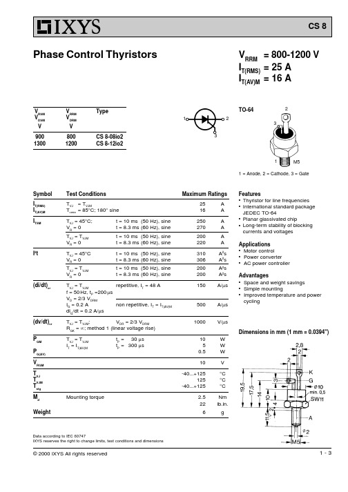
10-2
10-1
100
101
Fig. 8 Transient thermal impedance junction to heatsink
d = 30° d = 60° d = 120° d = 180°
d = DC
RthJH for various conduction angles d:
d
DC 180° 120°
© 2000 IXYS All rights reserved
3-3
Mounting torque
Maximum Ratings
25
A
16
A
250
A
270
A
200
A
220
A
310Biblioteka A2s306A2s
200
A2s
200
A2s
150 A/ms
500 A/ms
1000 V/ms
10 5
0.5
10
-40...+125 125
-40...+125
2.5 22
6
W W W
V
°C °C °C
TO-64
2
1
2
3
3
1
M5
1 = Anode, 2 = Cathode, 3 = Gate
Symbol I
T(RMS)
IT(AV)M I
TSM
I2t
(di/dt)cr
(dv/dt)cr PGM P
G(AV)
VRGM TVJ T
VJM
Tstg M
d
Weight
Test Conditions
T =T
- 1、下载文档前请自行甄别文档内容的完整性,平台不提供额外的编辑、内容补充、找答案等附加服务。
- 2、"仅部分预览"的文档,不可在线预览部分如存在完整性等问题,可反馈申请退款(可完整预览的文档不适用该条件!)。
- 3、如文档侵犯您的权益,请联系客服反馈,我们会尽快为您处理(人工客服工作时间:9:00-18:30)。
± 2.5V to ±15V ± 2.5V to ±15V ±15V ±15V ±15V ±15V ± 5V ± 2.5V ±15V ± 5V ± 2.5V ±15V ± 5V ± 2.5V
元器件交易网
LT1363
ELECTRICAL CHARACTERISTICS
SYMBOL VOUT PARAMETER Output Swing CONDITIONS
Wideband Amplifiers Buffers Active Filters Video and RF Amplification Cable Drivers Data Acquisition Systems
TYPICAL APPLICATIO
2
Cable Driver Frequency Response
AV = –1 Large-Signal Response
0 VS = ± 2.5V
GAIN (dB)
VS = ±15V VS = ± 5V VS = ±10V
IN
–2
–4
+
LT1363 – 510Ω 510Ω
75Ω
OUT 75Ω
–6
–8 1 10 FREQUENCY (MHz) 100
1363 TA02
PACKAGE/ORDER INFORMATION
TOP VIEW NULL 1 8 7 6 5 N8 PACKAGE 8-LEAD PDIP
TJMAX = 150°C, θJA = 130°C/ W
NULL V+ VOUT NC
ORDER PART NUMBER LT1363CN8
–IN 2 +IN 3 V– 4
PSRR AVOL
Power Supply Rejection Ratio Large-Signal Voltage Gain
2
U
U
W
W W U
W
(Note 1)
36V
Operating Temperature Range (Note 8) ...–40°C to 85°C Specified Temperature Range (Note 9) ....–40°C to 85°C Maximum Junction Temperature (See Below) Plastic Package ................................................ 150°C Storage Temperature Range ..................–65°C to 150°C Lead Temperature (Soldering, 10 sec).................. 300°C
1363 TA01
UUຫໍສະໝຸດ 1元器件交易网LT1363
ABSOLUTE MAXIMUM RATINGS
Total Supply Voltage (V+ to V –) ...............................
Differential Input Voltage (Transient Only) (Note 2)................................... ±10V Input Voltage ............................................................ ±VS Output Short-Circuit Duration (Note 3) ............ Indefinite
The LT1363 is a high speed, very high slew rate operational amplifier with excellent DC performance. The LT1363 features reduced supply current, lower input offset voltage, lower input bias current and higher DC gain than devices with comparable bandwidth. The circuit topology is a voltage feedback amplifier with the slewing characteristics of a current feedback amplifier. The amplifier is a single gain stage with outstanding settling characteristics which makes the circuit an ideal choice for data acquisition systems. The output drives a 150Ω load to ±7.5V with ±15V supplies and to ±3.4V on ± 5V supplies. The amplifier is also capable of driving any capacitive load which makes it useful in buffer or cable driver applications. The LT1363 is a member of a family of fast, high performance amplifiers using this unique topology and employing Linear Technology Corporation’s advanced bipolar complementary processing. For dual and quad amplifier versions of the LT1363 see the LT1364/1365 data sheet. For 50MHz amplifiers with 4mA of supply current per amplifier see the LT1360 and LT1361/1362 data sheets. For lower supply current amplifiers with bandwidths of 12MHz and 25MHz see the LT1354 through LT1359 data sheets. Singles, duals, and quads of each amplifier are available.
Consult factory for Industrial and Military grade parts.
ELECTRICAL CHARACTERISTICS
SYMBOL VOS PARAMETER Input Offset Voltage CONDITIONS (Note 4)
TA = 25°C, VCM = 0V unless otherwise noted.
VSUPPLY ±15V ± 5V ± 2.5V ± 2.5V to ±15V ± 2.5V to ±15V MIN TYP 0.5 0.5 0.7 120 0.6 9 1 12 50 5 3 12.0 2.5 0.5 13.4 3.4 1.1 –13.2 –12.0 –3.2 –2.5 –0.9 –0.5 84 76 66 90 ±15V ±15V ±15V ± 5V ± 5V ± 2.5V 4.5 3.0 2.0 3.0 2.0 2.5 90 81 71 100 9.0 6.5 3.8 6.4 5.6 5.2 MAX 1.5 1.5 1.8 350 2.0 UNITS mV mV mV nA µA nV/√Hz pA/√Hz MΩ MΩ pF V V V V V V dB dB dB dB V/mV V/mV V/mV V/mV V/mV V/mV
, LTC and LT are registered trademarks of Linear Technology Corporation. C-Load is a trademark of Linear Technology Corporation
U APPLICATIO S
s s s s s s
Input Voltage Range –
CMRR
Common Mode Rejection Ratio
VCM = ±12V VCM = ±2.5V VCM = ±0.5V VS = ±2.5V to ±15V VOUT = ±12V, RL = 1k VOUT = ±10V, RL = 500Ω VOUT = ±7.5V, RL = 150Ω VOUT = ±2.5V, RL = 500Ω VOUT = ±2.5V, RL = 150Ω VOUT = ±1V, RL = 500Ω
元器件交易网
LT1363 70MHz, 1000V/µs Op Amp
FEATURES
s s s s s s s s s s s s s s s s
DESCRIPTIO
70MHz Gain Bandwidth 1000V/µs Slew Rate 7.5mA Maximum Supply Current 9nV/√Hz Input Noise Voltage Unity-Gain Stable C-LoadTM Op Amp Drives All Capacitive Loads 1.5mV Maximum Input Offset Voltage 2µA Maximum Input Bias Current 350nA Maximum Input Offset Current 50mA Minimum Output Current ±7.5V Minimum Output Swing into 150Ω 4.5V/mV Minimum DC Gain, RL=1k 50ns Settling Time to 0.1%, 10V Step 0.06% Differential Gain, AV=2, RL=150Ω 0.04° Differential Phase, AV=2, RL=150Ω Specified at ± 2.5V, ±5V, and ±15V