美国peterpaul高压电磁阀全集
HOERBIGER P20型号压电气动开关阀简要操作说明书
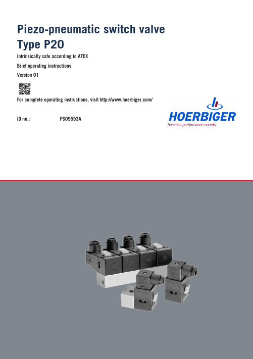
Piezo-pneumatic switch valve Type P20Intrinsically safe according to ATEXBrief operating instructionsVersion 01For complete operating instructions, visit /ID no.:PS09553ATable of contents1Note for using the brief operating instructions (3)2Ex characteristics (3)2.1Thermal Ex characteristics (3)3Product description (4)3.1Connections (4)3.2Technical data (5)4Assembly and installation (6)4.1Assembly (6)4.2Electrical installation (8)4.3Device socket (8)4.4Connect control cable to device outlet (9)5Start-up (10)5.1Start-up (10)5.2Manual operation (11)6Repair and maintenance (11)1Note for using the brief operating instructionsThese brief operating instructions do not replace the associated operating in-structions for this product (PS09552A).The brief operating instructions describe the pneumatic and electrical connec-tion of the device, as well as its start-up. They include notes about electricaland pneumatic characteristics.The brief operating instructions do not include any basic safety instructionsand warnings. Therefore, they may only be used by qualified personnel whohave read and understood the operating instructions belonging to the product.These operating instructions can be downloaded from the HOERBIGERcompany website .For additional information, contact the manufacturer at the following address:HOERBIGER Flow Control GmbHSüdliche Römerstraße 1586972 AltenstadtGermanyInformation on the Internet: 2Ex characteristics2.1Thermal Ex characteristicsThe following safety-technical ambient temperatures in various temperatureclasses apply for use in areas subject to explosion (see valve type plate):The table serves to explain Ex-technical data and not as specification for thevalves. In normal operation, intrinsic heating is very slight.The function of the valves is only given in the temperature range specified inthe current data sheet.3Product description3.1ConnectionsThe connections shown for the single connection plate are repeated on theconnection plates 2 and 4 times for the battery mounting.With manual operation, the valve can be activated manually and withoutelectrical activation.1423Fig. 1: Side view12Fig. 2: Side view1 2 34 6 5Fig. 3: P20 valve can be mounted on connection plate, 1x3.2Technical dataGeneral technical dataInstallation position Any (preferred position: plug on top);possible compromising of emergency manual operationdepending on installation positionMedium 1)Compressed air and nitrogenAccording to ISO 8573-1:2010 (7:3:4)On-time (ED)100 % ED with maximum 6000 hours constantoperationProtection type (IP) 2)IP54 according to DIN EN 60529/A1:2000Connection Device outlet according to DIN EN175301-803A1) Use below the freezing point requires dried air (pressure dew point 10 Kbelow ambient or medium temperature)2) Only with mounted device outlet and correctly connected control cableSubject to change without noticeSafety technical data according to EU design type certificateHOERBIGER code PT(63)PM(64)PN(61))9 V16 V30 VVoltage (UiCurrent (I)Not relevanti)12 nF12 nF12 nFExternal capacity (CiExternal inductance (L)Negligiblei4Assembly and installation4.1AssemblyDANGERMortal danger due to electrical voltage!■Switch off current before assembling and dismantling the valve.WARNINGDanger of crushing due to uncontrolled movement of the machinesPersonal injury and/or property damage possible.■Before restarting the system, take measures to prevent uncontrolledmovement of the machines.■Make sure that nobody is in the danger zone.WARNINGPersonal injury or property damage due to overpressureImproperly connected or defective pneumatic connections can loosen underpressure and cause extremely severe injuries.■Before assembly and dismantling of valves, switch off compressed air.■Make sure that there is neither input nor output pressure on the valves.■Only use components that are suitable for the permissible pressure ranges(see Technical data).■Proceed according to the special country-specific safety regulations.During installation of the valves in a system/machine in Ex areas, adhere tostandards EN1127-1 and relevant standards.WARNINGPersonal injury and property damage due to explosion■Only install devices within the categories specified on the data sheet.■Undertake installation of the intrinsically safe circuits according to the applicable building regulations (demonstrate knowledge of the builder,protected laying of the intrinsically safe circuits).■Maintain a safety distance of at least 50 mm between intrinsically safe and non intrinsically safe conductive connection parts.■For the interconnection of the devices with the intrinsically safe circuits of the associated tools, heed the respective maximum values of the fielddevice (valves) and the associated device in the interest of explosionprotection (proof of intrinsic safety).■In adverse ambient conditions, protect devices against spray water or dirt according to the protection type in the current data sheet.■For the special conditions of the EU design test certificate, see EU design type certificate.üThe pipelines and flange surfaces are free of contamination.üThe input pressure is at least 1 bar greater than the maximum required output pressure.1.Make sure that the appropriate O-rings or seals are inserted on the valveand the connection plate.2.Optionally mount the valve on a connection plate for the direct connectionof lines or on another pneumatic amplifier stage. NOTICE! Tighteningtorque: 120 ±5 NcmCompromising of the valve function possible■Make sure that the ventilation openings are not covered.■Protect valve against excessive heat radiation.■Protect valve against adverse ambient conditions such as spray water or dirt, in order to guarantee the protection type according to the data sheet.4.2Electrical installationDANGERMortal danger due to electrical voltage!■Only have the device connected to the power supply and control lines by a specialist.■Installation may only be done when the device is de-energized.■Secure against unintentional switching on.■Check electric cables for damage before connecting.For electrical connections in Ex areas, heed the applicable standards.DANGERMortal danger due to explosion■In Ex areas, only use with device outlet according to chapter Device socket, page 8.■Only use the device in areas subject to explosion together withappropriately approved voltage sources and safety equipment (e.g.separator modules or similar).■Have the interconnection assessed by a specialized electrician with knowledge of the set-up of electrical systems in areas subject toexplosion.■Lay intrinsically safe lines protected.■For the electrical connection, heed the prescribed switching voltage and the protection type of the cable.4.3Device socketThe device outlet corresponds to design A according to industry standardaccording to DIN EN 175301-803-A (= type GSD-30).Use in Ex areas is only permitted with GSD-30 design A according toDIN EN 175301-803-A.Use of a GSD with LED in Ex areas is not permitted.4.4Connect control cable to device outlet110113562993210847The terminal assignments are depicted at the top right of the figure.1.Loosen the connection locking screw (11).2.Remove device outlet (10) from the blade contacts of the valve (1).NOTICE! Heed the installation position of the plug seal (8). The seal must lie correctly and flat.3.Pull the plug locking screw completely out of the device outlet (10).4.Pull the connection block (2) completely out of the device outlet with a screwdriver.5.Turn the screw connection (7) out of the device outlet.6.Remove the washer (6) and seal (5) from the device outlet.7.Feed the control cable (4) through the screw connection (7), washer (6),seal (5) into the device outlet.8.Adjust the control cable of the seal in diameter so that the cable is tight in the seal.9.Remove insulation at the end of the control cable. NOTICE! Do not damage the two wires.10.Strip the wires with a cable stripper. NOTICE! For the installation, a two-linecable is sufficient.11.Clamp both wires of the cable to the screw terminals of the connectionblock: Wire “0 Volt” to terminal 1 (3), wire “control voltage” to terminal 2(9). NOTICE! The ground clamp is not used. The terminal numbering isengraved in both sides of the connection block.12.Place the seal (5), washer (6), and the screw connection (7) to the controlcable.13.Turn screw connection in the device outlet.14.Place device outlet with connected cable on the contacts of the valve.15.Tighten with plug locking screw. NOTICE! Make sure that the plug seal (8) isplaced on the valve over the blade contacts and there is no strain on thecables.5Start-up5.1Start-upWith use in environments with flammable gases, heed the Ex directive andother applicable regulations and the respectively valid local regulations (e.g.flush with inert gas, avoid adiabatic processes, etc.).WARNINGPersonal injury and property damage possible■Only have the start-up done by people who have sufficient knowledge andexperience with respect to compressed air systems and the machine/system to be started up.■Before operation with combustible gases, consult the manufacturer.■Heed additional measures according to the local set-up provisions(e.g. incorporation into the repeated pressure test).■For start-up of the valves, adhere to the following sequence of steps.üThe power supply is switched off.üThere is neither input nor output pressure present.1.Check proper mounting.2.Open compressed air supply.Brief operating instructionsPiezo-pneumatic switch valve Type P20WARNINGDanger of crushing due to uncontrolled movement of the machinesPersonal injury and/or property damage possible.■Before restarting the system, take measures to prevent uncontrolledmovement of the machines.■Make sure that nobody is in the danger zone.3.Switch on electric signal control.5.2Manual operationWith manual operation, the spool valve can be operated without electricalactivation. It functions both by pressing a button and by locking.■By pressing a button:–On: by pressing the activation button.–Off: by releasing the activation button.6Repair and maintenance1.Only have repair work on the valve performed by the manufacturer sinceonly the manufacturer has the equipment for optimal adjustment afterrepair and can therefore guarantee perfect function.2.Do NOT maintain the inner parts of the device.3.Send the complete valve to the manufacturer for maintenance and service.All rights, errors and changes reserved.Copyright by HOERBIGER 2018PS09553A。
Model 261系列交替电源电磁阀说明书
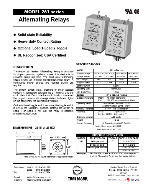
SPECIFICATIONS**order 8-pin socket # 51X120DESCRIPTIONThe Model 261 series Alternating Relay is designed for duplex pumping systems where it is desirable to equalize pump run time. The solid state alternating circuit drives an internal electromechanical relay.A continuous power source and control switch are required.The control switch (float, pressure or other isolatedcontact) is connected between the L1 terminal and the control terminal. Each time the control switch is opened the output contacts will change states. Indicator lights on the case show the internal relay status.On the optional toggle switch versions, the toggle switchisset to the NORMAL position. Setting the switch to Load 1 or Load 2 will lock the relay in position, preventing alternation. DIMENSIONS - 261S or 261DX● Solid-state Reliability ● Heavy-duty Contact Rating ● Optional Load 1-Load 2 Toggle ● UL Recognized; CSA Certified*add 3/4” (0.75) for toggle clearance on applicable models3.77“3.23“1.95“1.95“TIME MARK is a division ofTelephone:Main - (918) 438-1220 Sales - (800) 862-2875 Fax: (918) 437-7584E-mail: *******************Internet:12/2012© 2012 TIME MARK CORPORATION11440 East Pine Stree t Tulsa, Oklahoma 74116INSTALLATIONConnect wiring to the socket as indicated in the following examples.The Model 261 series Alternating Relays are extremely versatile and can be used in many other configurations besides those shown. Any type of switch (float, pressure, etc.) can be used as the control switch; however, it must be connected as shown (from L1 to the control input) or the alternator will not function properly.On Toggle Versions: For normal operation (alternating loads) set the toggle switch on the top of the case to the “normal” position. Setting the toggle switch to either “1” or “2” will lock the alternator in that position.TYPICAL APPLICATION: 261SNOTE: All drawings shown with no power applied.TYPICAL APPLICATION: 261D10264891131RL1RL2TYPICAL APPLICATION: 261DXKEEP THIS DATA SHEET FOR FUTURE REFERENCE.GENERAL SAFETYPOTENTIALLY HAZARDOUS VOLTAGES ARE PRESENT AT THE TERMINALS OF THE MODEL 261. ALL ELECTRICAL POWER SHOULD BE REMOVED WHEN CONNECTING OR DISCONNECTING WIRING.THIS DEVICE SHOULD BE INSTALLED AND SERVICED BY QUALIFIED PERSONNEL.Installation InstructionsTIME MARK is a division ofTelephone: Main - (918) 438-1220 Sales - (800) 862-2875 Fax: (918) 437-7584E-mail: *******************Internet:12/2012© 2012 TIME MARK CORPORATION11440 East Pine Stree t Tulsa, Oklahoma 74116。
Bosch 系列 Sistema aislador de la li

uProporciona bucles de altavoces redundantes para sistemas de megafonía y alarma por vozuReduce notablemente el coste y la complejidad de las instalaciones, eliminando en gran medida el costoso cableado E30uSeis bucles de altavoces por unidad principal y hasta 50 tarjetas aisladoras por bucle uFunciona con alimentación de reserva de 24 y 48 VCCuModo de prueba de paseo y botón de prueba de instalación para facilitar la búsqueda de errores y la instalaciónEl sistema aislador de la línea de altavoces es una solución económicamente rentable para evitar la pérdida de la función de audio en sistemas demegafonía y alarma por voz como consecuencia de fallos en la línea de altavoces.Elimina en gran medida la necesidad de utilizar el costoso cableado E30 al emplear el método denominado cableado en bucle. El sistema estácompletamente supervisado y está perfectamente indicado para su uso en instalaciones comerciales,como edificios de oficinas y hoteles.Entre las aplicaciones habituales se incluyen:•Sistemas de megafonía que cubren amplias zonas:más de 25 altavoces por zona.•Alarma por voz: lugares que cuentan con varias salas en la misma zona de incendios.Resumen del sistemalos siguientes productos:Unidad principalPM1‑LISM6Las salidas de zona del sistema de megafonía/alarma por voz (1) están conectadas a la parte posterior de la unidad principal (2), que puede gestionar un total de seis bucles de altavoz (500 W) (3).El estado de cada bucle se indica mediante los LED del panel frontal de la unidad principal. El panelfrontal también tiene indicadores LED para indicar el estado del suministro de alimentación y del suministro de la batería de reserva. Todos los indicadores de fallo en el panel frontal están vinculados a relés de fallo en el panel posterior de la unidad principal.Tarjeta aisladoraSuministrado con carcasa con clasificación IP30:PM1-LISSLas tarjetas aisladoras (4) se conectan en cadena en el bucle de altavoz y distribuyen audio desde el sistema de megafonía/alarma por voz a través de la unidad principal hasta los altavoces (5).Su función principal es:•Detectar y aislar cortocircuitos en el segmento adyacente.•Detectar y bloquear circuitos abiertos, cortocircuitos y sobrecargas en una derivación.Se puede instalar un máximo de 50 tarjetas aisladorasen cada bucle de altavoz.La tarjeta aisladora tiene dos conectores de audio de 100 V para conectar a ambos lados del bucle de altavoz y un tercer conector de audio de 100 V para crear una derivación para uno o más altavoces. Se proporcionan ajustes de puente para establecer elnivel de potencia admisible del altavoz (10, 36, 100 W o 10 W con filtro de tono piloto de 20 kHz) y otros ajustes de supervisión.La tarjeta aisladora tiene un LED de prueba/fallo. Este LED está visible cuando se monta la tarjeta en la carcasa suministrada, facilitando así la búsqueda de errores en el sistema.Tarjeta de bloqueo de CCPM1‑LISDLa tarjeta de bloqueo de CC bloquea la corrientecontinua y proporciona protección contra sobrecargas mediante la limitación de corriente. Cuenta con las mismas conexiones que la tarjeta aisladora, y permite una conexión rápida y cómoda del bucle de altavoz y de las conexiones de derivación (carga de altavoces de 20 W como máximo). La tarjeta de bloqueo de CC puede montarse dentro de algunos altavoces Bosch.Funciones básicasControles e indicadoresEl sistema aislador de la línea de altavoces estácompletamente supervisado; los fallos notificados no son permanentes. No hay controles de operador en la parte frontal ni en los paneles posteriores de la unidad principal. La interfaz de usuario en el panel frontal consta de indicadores LED que indican las siguientes condiciones:•Modo de prueba de paseo •Fallo•Inicialización de bucle •Bucle correctoTambién se indica el estado del suministro dealimentación y del suministro de la batería de reserva.El panel posterior contiene las interconexiones, el selector de tensión, el interruptor de alimentaciónprincipal y los interruptores DIP para fines de prueba y configuración.Certificados y homologaciones CertificacionesCumplimientosPlanificaciónConexiones y conmutadores en la parte posterior de la unidad principal1.Conexión en bucle (6x): entrada; envío, retorno2.Conexión de salida de fallo por bucle3.LED de bucle correcto por bucle4.LED de fallo de conexión por bucle5.Interruptores DIP por bucle: desactivar bucle;cortocircuito a tierra/esclavo; prueba de paseo6.Salidas de fallo común: general; alimentación; batería;cortocircuito a tierra7.Interruptor DIP: supervisión de alimentación;supervisión de batería8.Interruptor de selección de tensión: 115/230 VCA9.Conector de entrada de alimentación de reserva deCC: 24-48 VCC10.Interruptor de selección de subida de toma de tierra11.Interruptor de alimentación principal de CA12.Toma de entrada principal de CA de 115/230 VCA Opciones de instalaciónOpción de instalación 1: una tarjeta aisladora para cada altavoz5Opción de instalación 2: bifurcación de altavoces conectados a una placa aisladora5Opción de instalación 3: altavoces conectados entre tarjetas aisladorasOpciones de instalación combinadasPiezas incluidasCantidad ComponentePM1‑LISM6 – Unidad principal 1Unidad principal 1Instrucciones de seguridad1Aviso con instrucciones para la descarga manual 1Cable de alimentación principal 1Juego de conectores1Juego de soportes de montaje de 19 pulgadas, 2U PM1‑LISS – Placa aisladora1Tarjeta aisladora 1Juego de conectores 1Carcasa con clasificación IP301Resistencia de fin de línea (47 kilohmios, 0,5 W)1Bridas antitironesPM1-LISD – Tarjeta de bloqueo de CC 1Tarjeta de bloqueo de CC 1Juego de conectoresPM1-LISM6Especificaciones eléctricasConsumo de energía de la batería 24 VConsumo de energía de la batería 48 V Especificaciones mecánicasEspecificaciones ambientalesPM1-LISSEspecificaciones eléctricasEspecificaciones mecánicasEspecificaciones ambientalesResistencia de fin de línea Especificaciones eléctricasPM1-LISDEspecificaciones eléctricasEspecificaciones mecánicasEspecificaciones ambientalesInformación sobre pedidosSistema aislador de la línea de altavoces principal Unidad principal del sistema aislador de la línea de altavoces: crea seis bucles de altavoz redundantes, 500 vatios por bucle, máximo de 50 placas aisladoras por bucle.Número de pedido PM1-LISM6Aislador de la línea de altavoces con carcasaPlaca aisladora para distribuir audio desde el sistema de megafonía/alarma por voz, a través de la unidad principal hasta los altavoces.Número de pedido PM1-LISSPlaca de bloqueo de CC del altavozSi el altavoz no está equipado con una placa aisladora, se debe instalar en el sistema una placa de bloqueo de CC para el bloqueo de CC y la protección en caso de sobretensión.Número de pedido PM1-LISDRepresentada por:Spain:Americas:America Latina:Bosch Security Systems, SAUC/Hermanos García Noblejas, 19 28037 MadridTel.: +34 914 102 011Fax: +34 914 102 056**************************** www.boschsecurity.es Bosch Security Systems, Inc.130 Perinton ParkwayFairport, New York, 14450, USAPhone: +1 800 289 0096Fax: +1 585 223 9180***********************.comRobert Bosch LtdaSecurity Systems DivisionVia Anhanguera, Km 98CEP 13065-900Campinas, Sao Paulo, BrazilPhone: +55 19 2103 2860Fax: +55 19 2103 2862*****************************© Bosch Security Systems, SAU 2015 | Información sujeta a cambios sin previo aviso 137****8475|es,V3,01.Jul2015。
美国Eaton公司产品说明书:Eaton Moeller系列xPole - mRB4 6 RCBO

Eaton 120654Eaton Moeller series xPole - mRB4/6 RCBO - residual-current circuit breaker with overcurrent protection. RCD/MCB, 16A, 100mA, B-LS-Char, 3N pole, FI-Char: AGeneral specificationsEaton Moeller series xPole - mRB4/6 RCBO - residual-current circuit breaker with overcurrent protection120654401508118484280 mm 75.5 mm 70 mm 0.446 kg CE Marked RoHS conformCE mRB6-16/3N/B/01-AProduct NameCatalog Number EANProduct Length/Depth Product Height Product Width Product Weight Compliances Certifications Model CodeSwitchgear for residential and commercial applicationsmRB6Combined RCD/MCB devicesSwitchgear for industrial and advanced commercial applications Three-pole + N44BB16 A6 - 25 Ampere0.1 AType A, pulse-current sensitiveRCBO AC400 V230 V / 400 V400 V500 V4 kV30, 100, 300 MilliAmpere Partly surge-proof, 250 A 50 HzA6 kA6 kA6 kA0.5 x I∆n6 kA6 kA6 kAApplicationProduct rangeBasic functionProduct applicationNumber of polesNumber of poles (protected) Number of poles (total) Tripping characteristic Release characteristicRated currentRated current of product range Fault current rating Sensitivity typeType Voltage typeVoltage ratingVoltage rating at ACRated operational voltage (Ue) - maxRated insulation voltage (Ui)Rated impulse withstand voltage (Uimp)Rated fault currents of product rangeImpulse withstand currentFrequency ratingLeakage current typeRated switching capacityRated switching capacity (IEC/EN 60947-2)Rated switching capacity (IEC/EN 61009)Rated non-tripping currentRated short-circuit breaking capacity (EN 60947-2) Rated short-circuit breaking capacity (EN 61009) Rated short-circuit breaking capacity (EN 61009-1) Rated short-circuit breaking capacity (IEC 60947-2)0 kA 0.25 kAUndelayed Non-delayed 100 Ampere gL 3III245 mm480 mm70 mmTri-stable slide catch - enables removal from existing busbar combinationIP20IP40Twin-purpose1 - 25 Square MillimeterBusbar tag shroud to VBG41 mm²25 mm²1 mm²25 mm²2 mmIEC 68-2: 25 °C - 55 °C at 90 % - 95 % humiditySurge current capacityDisconnection characteristic TrippingBack-up fuseSelectivity class Overvoltage category Pollution degree FrameWidth in number of modular spacingsDevice heightBuilt-in depthMounting styleDegree of protectionDegree of protection (built in)Terminals (top and bottom)Solid terminal capacitiesTerminal protectionConnectable conductor cross section (solid-core) - min Connectable conductor cross section (solid-core) - max Connectable conductor cross section (multi-wired) - min Connectable conductor cross section (multi-wired) - max Material thicknessClimatic proofing16 A0 W 11.6 W 0 W0 W-25 °C 40 °C Meets the product standard's requirements.Meets the product standard's requirements.Meets the product standard's requirements.Meets the product standard's requirements.Meets the product standard's requirements.Does not apply, since the entire switchgear needs to be evaluated.Does not apply, since the entire switchgear needs to be evaluated.Meets the product standard's requirements.Does not apply, since the entire switchgear needs to be evaluated.Meets the product standard's requirements.Does not apply, since the entire switchgear needs to be evaluated.Does not apply, since the entire switchgear needs to be evaluated.Is the panel builder's responsibility.Is the panel builder's responsibility.Is the panel builder's responsibility.Rated operational current for specified heat dissipation (In) Heat dissipation per pole, current-dependentEquipment heat dissipation, current-dependentStatic heat dissipation, non-current-dependentHeat dissipation capacityAmbient operating temperature - minAmbient operating temperature - max 10.2.2 Corrosion resistance10.2.3.1 Verification of thermal stability of enclosures10.2.3.2 Verification of resistance of insulating materials to normal heat10.2.3.3 Resist. of insul. mat. to abnormal heat/fire by internal elect. effects10.2.4 Resistance to ultra-violet (UV) radiation10.2.5 Lifting10.2.6 Mechanical impact10.2.7 Inscriptions10.3 Degree of protection of assemblies10.4 Clearances and creepage distances10.5 Protection against electric shock10.6 Incorporation of switching devices and components10.7 Internal electrical circuits and connections10.8 Connections for external conductors10.9.2 Power-frequency electric strengthIs the panel builder's responsibility.Is the panel builder's responsibility.The panel builder is responsible for the temperature rise calculation. Eaton will provide heat dissipation data for the devices.Is the panel builder's responsibility. The specifications for the switchgear must be observed.Is the panel builder's responsibility. The specifications for the switchgear must be observed.The device meets the requirements, provided the information in the instruction leaflet (IL) is observed.3Concurrently switching N-neutralIEC/EN 61009eaton-xpole-mrb4-rcbo-catalog-ca019058en-en-us.pdfeaton-xpole-mrb6-rcbo-catalog-ca019057en-en-us.pdfDA-DC-03_mRB-3N03_mRB-3p_20041603_mRB-3N_281118eaton-mcb-xpole-mrb4-6-characteristic-curve.epseaton-xeffect-frbm6/m-characteristic-curve-002.jpgDimensions xPole mRB4/mRB6 3Neaton-xeffect-frbm6/m-dimensions-004.jpgeaton-mcb-xpole-mrb4-6-dimensions.eps3D Drawing xPole mRB4/mRB6 3Neaton-xpole-combined-mcb-rcd-device-rcbo-packaging-manual-multilingual.pdfIL019140ZUDA-CS-faz_3pn_4pDA-CD-faz_3pn_4pCharacteristics xPole mRB4/mRB6 3Neaton-mcb-xpole-mrb4-6-wiring-diagram.epsContact Sequence xPole mRB4/mRB6 3N10.9.3 Impulse withstand voltage10.9.4 Testing of enclosures made of insulating material 10.10 Temperature rise10.11 Short-circuit rating10.12 Electromagnetic compatibility10.13 Mechanical function Current limiting class FeaturesStandards Catalogues Certification reports Characteristic curve DrawingsInstallation instructions mCAD modelTime/current curves Wiring diagramsEaton Corporation plc Eaton House30 Pembroke Road Dublin 4, Ireland © 2023 Eaton. All rights reserved. Eaton is a registered trademark.All other trademarks areproperty of their respectiveowners./socialmediaeaton-xeffect-frbm6/m-wiring-diagram-002.jpg。
工控产品品牌大全

ABB 伺服电机AC TECH 变频器, 驱动器Advance Motion Controls 伺服控制器AXOR 伺服电机, 控制器AMK 伺服电机, 控制器ANIMATICS 伺服电机, 控制器ARNOLD MULLER 伺服电机, 控制器AEG 伺服电机, 控制器Andrive 伺服电机, 控制器BALDOR 伺服电机, 控制器BAUMULLER 伺服电机, 控制器BAUTZ 伺服电机, 控制器Bardac 伺服电机, 控制器CEM 伺服电机, 控制器CMC 伺服电机, 控制器Copley 伺服电机, 控制器CSR 伺服电机, 控制器DIERKING 伺服电机, 测速电机DriveTech 伺服电机, 控制器Drive Systems 伺服电机EAT 伺服电机, 控制器ELAU 伺服电机, 控制器Electrocraft 伺服电机, 控制器E.C.S 伺服电机, 控制器Elmo 伺服电机, 控制器EMOD 伺服电机Engel Hardt 伺服电机, 控制器EPH 伺服电机, 控制器Ferrocontrol 伺服电机, 控制器GALIL 伺服电机, 控制器GEC ALSTHOM 伺服电机, 控制器GEORGII KOBOLD 伺服电机, 控制器Giddings & Lewis 伺服电机及控制器Gould 伺服电机, 控制器Gettys 伺服电机, 控制器IIS 伺服电机, 控制器ID 伺服电机, 控制器HAUSER 伺服电机, 控制器HDD 伺服电机, 控制器HEYNAU 伺服控制器Hardmeier 伺服电机, 控制器Indramat 伺服电机, 控制器Inland 伺服电机, 控制器Infranor 伺服电机, 控制器IRT 伺服电机, 控制器ISOFLUX 伺服电机, 控制器Jetter 伺服电机, 控制器JVL 伺服电机, 控制器JUNG 伺服电机, 控制器KB 电机控制器Kollmorgen 伺服电机, 控制器Lenze 伺服电机, 控制器LEAG 伺服电机, 控制器LUST 伺服电机, 控制器MAGNETIC 伺服电机, 控制器Mayr 伺服电机, 控制器MA VILOR 伺服电机MCG 伺服电机, 编码器NUM 伺服电机, 控制器OSW ALD 伺服电机, 控制器PARVEX 伺服电机, 控制器PEERLESS-WINSMITH 伺服电机, 控制器POWERTEC 伺服电机, 控制器ProControl 伺服电机, 控制器SAD 伺服电机, 控制器SBC 伺服电机, 控制器Seidel 伺服电机, 控制器SELCA 伺服电机, 控制器SEM 伺服电机, 控制器SERV AX 伺服电机, 控制器Servomac 伺服电机, 控制器Selema 伺服电机, 控制器SIEMENS 伺服电机, 控制器SMB 伺服电机, 控制器SSB 伺服电机, 控制器Stromag 伺服电机, 控制器Systec 伺服电机, 控制器Slo-Syn 伺服电机, 控制器Superior Electric 伺服电机, 控制器TDE MACNO 伺服电机, 控制器VICKERS 伺服电机, 控制器Warner Swasey 伺服电机, 控制器Winkelmann 伺服电机, 及控制器编码器:Anilam 编码器ASM 编码器Avtron 编码器Baumer 编码器Carlen 编码器Clifton 编码器COPI 编码器DRC 编码器DEUTSCHMANN 编码器,凸轮控制器DUNCAN 编码器ELAP 编码器ELGO 编码器Eltra 编码器EMETA 编码器EPC 编码器ESTERS 编码器EUCHNER 编码器FRABA 编码器FSG 编码器FSI 编码器Fork 编码器Gaebridge 编码器Givi Misure 编码器GURLEY 编码器HAROWE 编码器HENGSTLER 编码器HEIDENHAIN 编码器HUBNER 编码器Hohner 编码器IHI 编码器IMG 编码器INDUCODER 编码器Industrial Encoder 编码器IDEACOD 编码器Jahannes Hubner 编码器JENA 编码器Kubler 编码器KEP 编码器Lenord+Bauer 编码器Leine & Linde 编码器Lake Shore 编码器LIKA 编码器Litton 编码器LTN 编码器Micronor 编码器MTL 编码器Photocraft 编码器Quantum 编码器Red Lion 编码器RENCO 编码器RSF 编码器SAIET 编码器Solartron 编码器SCANCON 编码器SELET 编码器STEGMANN 编码器SUMTAK 编码器SIKO 编码器SERVOTECHNIK 编码器STROTER 编码器TEKEL 编码器THALHEIM 编码器, 测速电机Torque Systems 编码器TR 编码器T+R 编码器TWK 编码器US DIGITAL 编码器W+S 编码器WACHENDORFF 编码器测速电机:Baumuller 测速电机EW HOF 测速电机HORN 测速电机NORIS 测速电机Servo-Tek 测速电机Thalheim 测速电机液压,气动元件大全ACL 电磁阀Airpot 气缸AIRTEC 气动元件ALCON 电磁阀ARGUS 液压元件ARO 气动元件ARON 液压元件ASK 液压元件及仪表BERARMA 叶片泵BIERI 液压元件Boll & Kirch 过滤器BUCHER 液压元件CASAPPA 液压元件CHAR-L YNN 液压马达CONTINENTAL 液压元件CONCORDIA 气动元件CPOAC 气动元件DAIKIN 液压元件DELTROL 液压元件Dynamco 电磁阀EDI 液压元件EMG 伺服阀EPE 过滤器EUGEN SEITZ 电磁阀FABCO-AIR 气动元件FLUTEC 液压元件FUJI ENGINEERING 电磁阀FUJIKIN 电磁阀GPA 电磁阀HPI 液压元件HYDROTECHNIC 液压元件HYDRONORMA 电磁阀HYDROTECHNIK 液压元件HYDROPA 液压元件HTF 液压元件ITAYA 公司齿轮泵Integrated Hydraulics 液压元件KANEKO 电磁阀konan 气动元件KEIHIN 电磁阀KV 电磁阀LUCIFER 电磁阀MARZOCCHI 泵,马达MAAG 油泵MAC 电磁阀MAGNET SCHULTZ 电磁阀Micro Precision 液压马达NIPPON OIL PUMP (NOP) 油泵NIPPON GEROTOR CO., LTD 公司油泵NKE 气缸, 气动手指NOK 气动元件Peter Paul 电磁阀Phd 油缸RACINE 油泵RICKMEIER 泵阀ROSS 电磁阀SC HYDRAULIC ENGINEERING 气动马达SCEM 电磁阀Schrader Bellows 气动元件Skinner 电磁阀Sterling 液压元件STORZ 油缸STUCCHI 单向阀SUN 液压元件SUMITOMO 齿轮泵TOGNELLA 液压元件TACO 气动元件Trochoid 油泵UCC 过滤器VERSA 电磁阀V & B SERVOCOMANDI 液压气动元件V on Ruden 液压马达, 齿轮头WEKUPO 柱塞泵Walther 快速接头WAIRCOM 气动元件Wilkeson 气动元件WSI 液压马达, 齿轮箱工业电气,传感器大全AECO 接近开关ACi 工业开关, 传感器Acromag 自动化产品ACU-RITE 自动化产品ACS 传感器, 自动化元件AEP 压力开关, 压力变送器ALLEMANO 压力仪表ALTHEN 传感器ALTMANN 电位计American Sensors 传感器ANILAM 自动化产品ANTUNES 压力开关AROMANIKKI 流量开关ASAHI 自动化仪表ASI 接近开关等自动化元件ASO 安全自动化元件ASTECH 传感器atc 自动化元件atr 自动化元件ATHENA 温控器AUTOTRON 传感器AUTOTECH 自动化元件BARKSDALE 压力, 温度仪表BACO 安全自动化产品BECKHOFF 自动化产品BENDER 自动化产品BENEDIKT 开关BERNSTEIN 传感器BETA 传感器Binding Union 公司过程控制仪表BIRCHER 安全自动化产品BRAUN 速度仪表BRODERSEN 继电器BROSA 力传感器BROSE 自动化显示仪表, 电源BROYCE CONTROL 控制继电器, 计时器BST 控制产品BTI 安全开关BTR 工业继电器BUHLER 液位开关Cabur 自动化元件CAL 温控器CANAAN 计时器CAPTRON 传感器CAREL 温度仪表CDC 自动化元件CEDES 传感器Celduc 自动化产品CEWE 自动化仪表C-mac 自动化产品COMAT 工业控制继电器COMECO 过程控制, 自动化元件CONTINENTAL 固态继电器, I/O模块, 温控器CONTRINEX 传感器C.Thiim 工业控制继电器CTI 公司控制模块DA TALOGIC 光电开关, 传感器DA TALOGICDL 光电开关, 传感器DAIICHI 传感器DELTA 传感器(钢铁行业用)DESIN 公司过程控制仪表DIELL 传感器DIGITEC 自动化仪表Digitronic 自动化元件Dinel 传感器DISIBEINT 控制继电器di-soric 传感器DITEL 仪表DIVERSIFIED 自动化仪表DSE 光电位移传感器DUELCO 安全继电器DVT 传感器EBM 力传感器ECS 自动化仪表, 元件EGE 传感器Elan 安全开关ELAP 自动化产品ELB 自动化元件ELBO 自动化元件elco 自动化产品ELECTRO CAM 限位开关, 编码器ELEKTRA 开关ELGO 自动化产品Eliwell 自动化元件ELOBAU 接近开关, 光电开关ELOTECH 温度控制器ELTIME 自动化仪表ELTROTEC 传感器ELCTRO-SENSORS 传感器Enraf 液位仪表ERO 自动化仪表ESTERS 速度传感器等自动化仪表E-T-A 自动化产品EUROSWITCH 液位开关, 压力开关fae 光电开关, 自动化元件fanal 自动化元件fanox 继电器等自动化元件FARGO 计时器, 计数器, 接近开关FASE 自动化仪表FE (FEMA ELECTRONIC ) 自动化产品FIAMA 传感器, 自动化仪表FIBER 自动化产品FIESSLER 传感器FIFE 自动化产品FLINTEC 重量传感器FOTOSTAR 传感器FRER 自动化仪表FRIZLEN 自动化产品DA TEXEL 信号调节仪表GEMCO 位移传感器GENTRAN 压力传感器, 仪表GEORGIN 压力,温度仪表GO SWITCH 限位开关Guard Master 安全自动化产品HENIX 自动化产品HEMOMA TIK 液位开关HERGA 自动化元件HESCH 过程控制, 自动化元件HIQUEL 自动化产品HiTECH 液位仪表HSB 自动化元件HOFFMAN 自动化产品, 工业配件HONIGMANN 张力传感器HONSBERG 自动化仪表Hornel 自动化元件HUBA 压力仪表IME 自动化仪表IMO 工业电气, 自动化元件INFRA 传感器IPF 传感器ISSC 接近开关ITT 压力仪表italcoppie 温度仪表JAQUET 速度传感器JAY 传感器JM CONCEPT 自动化元件JOKAB 安全自动化产品KAMAN 传感器KANSAI 液位开关KEP 自动化产品Kiepe 限位开关, 安全开关KINAX 角位移传感器KLASCHKA 传感器LOCON 传感器LORENZ 力传感器LOV ATO 电气元件LOVE 温控器LUTZE 自动化元件Macromatic 控制继电器, 时间继电器MAGNETROL 液位仪表MAGPOWR 张力控制仪表Matrix 传感器MDI 接触器MECHAN 安全开关MECT 自动化仪表MEGA TRON 元器件MESA 传感器Meto-fer 传感器MASTER-K 力传感器MD Micro Detector 传感器Microsonic 传感器MIDORI 电位器MIGATRON 超声波传感器MMT 液位控制仪表Moduloc 自动化产品Monarch 自动化产品MTE 电源过滤器MTE 工业电气自动化元件MULLER 工业传感器MULLER 计时器, 计数器Muller & Weigert 自动化仪表Muller & ziegler 变送器NAMCO 限位开关, 传感器NCC 继电器, 温控器, 液位控制仪表NEWPORT 温度,过程仪表NELSA 安全自动化产品NESSTECH 温度,压力开关NOBEL 重量传感器Nokeval 自动化元件NORIS 自动化元件NOVOTECHNIK 位移传感器OFFICINE OROBICHE 液位开关OMC 自动化元件, 阀门ONO SOKKI 传感器OPTRONIC 传感器Pantron 光电开关, 传感器Pauly 光电控制产品PDI 压力开关PECO 自动化产品PETER 电气自动化元件PIL 超声波传感器PINNACLE 安全传感器Pinter 压力开关PIXSYS 过程控制, 自动化元件PIZZATO 安全开关PHILIPS 温度控制器PR 变送器, 过程仪表PRECISION DIGITAL 自动化仪表PRIME 金属检测传感器PROXIMITY 自动化元件Proxitron 传感器PROXISTOR 接近开关, 光电开关Pulsotronic 接近开关R-K 自动化元件RCI 传感器RED LION 自动化产品REDINGTON 计时器, 计数器REED 传感器REER 安全自动化产品REES 安全自动化产品REGLOMAT 安全自动化产品RHEINTACHO 速度控制仪表RIESE 安全继电器RUEGER 温度, 压力仪表SAIET 传感器(光电开关, 接近开关, 编码器) SANW A 压力开关SATRON 压力仪表SCAIME 重量传感器SCHAEVITZ 传感器SCHLEICHER 继电器Schonbuch 传感器Schluter 光电开关, 传感器SCHMIDT 仪表SCHRACK 继电器SCHRAMM 热电偶SD SENSORS 压力, 液位仪表SECA TEC 自动化产品SELET 自动化产品SENECA 公司信号调节产品, 隔离开关SENSOREX 传感器Sensopart 传感器SENSOTEC 传感器SENTROL 安全自动化元件SIE 传感器Siebert 显示仪表SIEI 自动化元件SIMPSON 自动化仪表SITRON 光电开关SKAN-A-MATIC 光电开关Smith Systems 传感器SNT 传感器Soclair 变送器, 自动化元件Solartron 自动化产品SONOTEC 超声波传感器SONTHEIMER 开关Spohn & Burkhardt 电位器, 编码器States 公司终端开关板,测试开关板Sti 传感器Stedham 接近开关STM 传感器STS 压力,液位,温度变送器SUCO 压力仪表SYNATEL 传感器Tapeswitch 传感器TC 温度仪表Tecfluid 液位仪表TECNOLOGIC 自动化元件tec sis 自动化产品TELCO 传感器TELE 继电器Tenor 自动化元件TER 限位开关TESCH 自动化产品THERMOSYSTEMS 自动化元件Tippkemper 传感器Tri-tronics 光电开关Trans-Tek 传感器TRUMETER 自动化产品VESTER 传感器WALTER MULLER 自动化元件Wenglor 传感器WESTCON 自动化仪表WIELAND 继电器Wilkerson 信号调节仪表Williamson 温度仪表ZIEHL 自动化元件工业泵,阀门总汇A-T Controls 阀门Amisco 电磁阀AMETEK 风机AIRPEL 过滤装置ARPUMA 真空泵COAX阀门DELIMON 润滑泵, 阀, 控制器DROPSA 润滑泵, 阀, 控制器ERA SIB 电磁阀FURON 阀门GEMU 阀门GEORG FISCHER 阀门Gerhard GOTZE 阀门HOmatic 阀门Interlube 润滑泵, 分配器, 阀, 控制器Knoll 泵Lubrotec 润滑泵MCLEAN 风机MECAFLUID 润滑泵, 分配器, 阀, 控制器REBS 润滑泵, 分配器, 阀, 控制器riba 压力调节器, 阀门定位器ROCKY 阀门SASCO 阀门SOMAS 阀门TOKYO DANLE 阀门Uni gerate 公司阀门VERIFLO 调节阀VOGEL 润滑泵, 分配器, 阀, 控制器VOGEL Fluidtec 公司润滑泵, 分配器, 阀, 控制器Varisco 泵WILL Y VOGEL 润滑泵, 分配器, 阀, 控制器WAREX 阀门WOERNER 润滑泵, 分配器, 阀, 控制器电机,减速机,齿轮箱大全ABB 电机AEG 电机,AEG 振动电机ABM 电机ASEA 电机ATB 电机A VITEQ 振动电机BALDOR 电机BAUTZ 电机BAUMULLER 电机BAUER 电机BEN 电机BENZLERS 减速机BERENDSEN 马达BESEL 电机BISON 减速机BODINE 电机, 减速机BONORA 电机BROOK CROMPTON 电机BROOK HANSEN 电机Buhler 电机BULL 电机CAMCO 减速机CARL BOCKWOLDT 电机Carpanelli 电机CEG 电机CELMA 电机CEMP 电机CMD 减速机COEL 刹车电机Coverco 电机DART 电机调速控制器DALTON 减速机Dutchi 电机Dietz 电机, 变频器EBM 电机EFACEC 电机Elektrim 电机EMIT 电机EMOD 电机ELMO 电机ELVEM 电机Euromotori 电机FAURNDAU 电机FFD 电机FIMET 电机FIMEC 电机FLEXALINE 减速机FUJI 电机GE 电机GROSCHOPP 电机, 减速机GROVE GEAR 减速机GUDEL 减速机HANNING 电机HITACHI 电机Helmke 电机HOFFMANN 电机IEG 电机IMS 减速机IMPERIAL 电机, 减速机indukta 电机KB 电机控制器Kuenle 电机KESSLER 电机KAISER 电机LAFERT 电机LAMMERS 电机LENZE 电机LEROY SOMER 电机LINCOLN 电机MEZ 电机Micron 齿轮头MORSE 离合器MARELLI 电机MARA THON 电机Mawdsley 电机MGM 电机NECKAR 电机Nord 电机, 减速机OGURA 离合器OEMER 电机ORTLINGHAUS 离合器PERSKE 电机PIV 减速机REGGIANA 减速机REXNORD 减速机Rotor 电机SCHORCH 电机SEIPEE 电机SEIMEC 电机SESAME 齿轮电机SICEI 电机SICME 电机Slo-Syn 电机及控制器STROTER 减速机Superior 电机及控制器TEM 电机THRIGE 电机THOMSON MICRON 齿轮头TOSHIBA 电机US GEARMOTORS 减速机US MOTORS 电机V ARVEL 减速机VECTRON 变频器VOGEL 减速机WATT 减速机WEG 电机Wurges 振动电机ZAE 减速机轴承,离合器,电源大全AETNA 轴承AMERICAN ROLLER 轴承ANDREWS 轴承AURORA 轴承BARDEN 轴承BCA 轴承BOWER 轴承Browning 轴承齿轮箱减速机COOPER 轴承DODGE 轴承齿轮箱减速机FRDERAL 轴承HUB CITY 轴承齿轮箱减速机KAYDON 轴承KSK 轴承LINK BELT 轴承Martin 链轮等机械传动元件MB 轴承McGiLL 轴承MPB 轴承MRC 轴承NB 线性轴承NDH 轴承NICE 轴承RBC 轴承REXNORD 轴承sealMaster 轴承Schatz 轴承Schneeberger 线性轴承UNION TOOL 线性轴承Triangle 轴承离合器, 刹车:ASAHI 离合器BOSTON GEAR 公司离合器, 传动产品CAMCO 离合器, 刹车COMINTEC 离合器, 刹车DESCH 离合器, 刹车Dings 离合器, 刹车FORVE CONTROL 离合器, 刹车FORMSPRAG 离合器, 刹车GMN 离合器, 刹车GOIZPER 离合器, 刹车HORTON 离合器, 刹车Industrial Clutch 离合器, 刹车MORSE 离合器, 刹车NEXEN 离合器, 刹车OSAKI 离合器, 刹车REXNORD 离合器, 刹车SANYO 离合器, 制动器STEARNS 离合器, 刹车Stieber 离合器, 刹车STROMAG 离合器, 刹车Warner 离合器, 刹车Wichita 离合器, 刹车电源, 变压器:ACME 电源,变压器BLOCK 电源,变压器cabur 电源DEUTRONIC 电源DELTA 电源DONGAN 变压器, 电源EUROTEK 电源FEAS 电源GE 电源, 变压器HAMMOND 变压器HEVI-DUTY 电源, 变压器HUHN ROHRBACHER 电源Instrument Transformers Inc 变压器International Power 电源KACO 电源及整流装置MARCUS 变压器MGV 电源OSAKI 电源POWER CONTROL 电源POWER ONE 电源POWERTRONIC 电源PULS 电源RA THGEBER 电源SOLA 电源SBA 电源TOKYO RIKOSHA 电压调节器TRACO 电源YAMABISHI 电源DAIDO 联轴器KOP-FLEX 联轴器LOVEJOY 联轴器R+W 联轴器ZERO-MAX 联轴器SIT 公司传动元件T.B. WOOD 公司传动产品DUFF-NORTON 执行器, 旋转接头OHIO GEAR 齿轮箱OSAKA DENKI 焊接设备及变压器等附件。
低功耗电磁阀全集
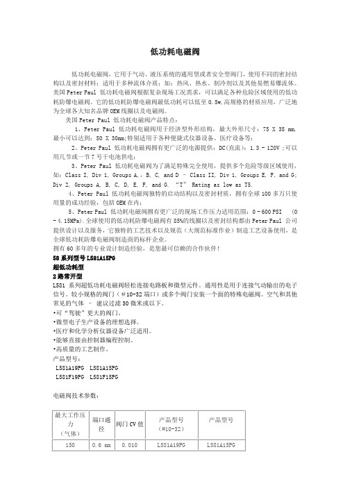
用几节或一节 7 号干电池供电; 3、Peter Paul 低功耗电磁阀为了满足特殊完全使用,提供多个危险等级区域使用,
如:Class I, Div 1, Groups A,,B, C, and D – Class II, Div 1, Groups E, F, and G; Div 2, Groups A, B, C, D, E, F, and G. “T” Rating as low as T5.
4、Peter Paul 低功耗电磁阀独特的启动结构以及密封材质,拥有全球 100 多万只使 用量的成功经验,包括 OEM 在内;
5、Peter Paul 低功耗电磁阀拥有更广泛的现场工作压力适用范围:0 - 600 PSI (0 - 4.15MPa).全球使用的低功耗防爆电磁阀有 85%的线圈以及密封结构都由 Peter Paul 公司 提供设计以及服务,它独特的工艺技术以及规范(大规范标准作业)制造工艺设备使用,是 全球低功耗防爆电磁阀制造商的标杆企业。 拥有 60 多年的专业设计制造经验,是您最可信赖的合作伙伴! 58 系列型号 L581A15PG 超低功耗型 2 路常开型 L581 系列超低功耗电磁阀轻松连接电路板和微型元件。通用性是用于连接气动输出的电子 信号。较小规格的阀门(#10-32 端口)或多个阀门安装一个面的特殊电磁阀。空气和其他 常见的气体 – 建议过滤 30 微米或以下。 •可“驾驶”更大的阀门。 •微型电子生产设备的理想选择。 •医疗和化学分析仪器设备广泛适用。 •能够直接由控制器编程控制。 •高质量的工艺制作。 产品型号:
派克各式电磁阀及原理介绍

派克各式电磁阀及原理介绍派克各式电磁阀及原理介绍上海维特锐专业从事各种国外工控自动化产品的进口贸易。
主要经营品牌如下:德国品牌:KRACHT 克拉克、VSE 威士、HYDAC贺德克、BUCHER布赫、P+F 倍加福FESTO 费斯托、IFM 易福门、SIEMENS 西门子、SICK 施克、TURCK图尔克、E+H 恩德斯豪斯、 LEUZE 劳易测、巴士德Barksdale、德国PLATING ELECTRONIC、 KOBOLD 科宝、巴鲁夫BALLUFF、海隆HERION 、HEIDENHAIN海德汉、HAWE哈威美国品牌:PARKER 派克、ASCO 阿斯卡、美国 ACE、VICKERS 威格士、MAC、葆德BALDOR、MOOG穆格、NUMATICS 纽曼帝克、JOUCOMATIC 捷高意大利品牌:ATOS 阿托斯、VESTA维斯塔、CAMOZZI 康茂盛、迪普马duplomatic 英国品牌:牛顿NEWTONS4TH日本品牌:SMC、CKD 喜开理、油研 YUKEN、NACHI 不二越TAIYO 太阳铁工、SUNX 神视、DAIKIN 大金液压KEYENCE 基恩士、OMRON 欧姆龙、KOGANEI 小金井派克各式电磁阀及原理介绍派克电磁阀是由电磁线圈和磁芯组成,是一个含有一个或几个孔的阀门。
当线圈通电或断开时,磁芯的操作将导致流体通过阀体或被切断,以便改变流体的方向。
电磁阀的电磁部件由固定铁芯、移动铁芯、线圈等组成。
阀体由滑动阀芯、滑动阀套、弹簧座等组成。
电磁线圈直接安装在阀体上,阀体密封在密封管中。
形成一个简单而紧凑的组合。
我们生产中常用的电磁阀有二位三环、二位四环、二位五环等。
这里我们首先谈一下二的含义:对于电磁阀是带电的和功率损失的,对于阀门的控制是开闭的。
它由阀体、阀盖、电磁元件、弹簧和密封结构等组成。
动铁芯底部的密封块借助弹簧压力关闭阀体进气口。
通电后,电磁铁被吸入,动铁芯上部的弹簧密封块封闭出风口,气流从进气口进入膜头,起到控制作用。
四种测量导线断点的方式
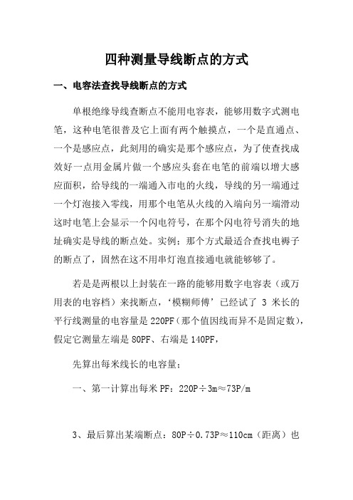
四种测量导线断点的方式一、电容法查找导线断点的方式单根绝缘导线查断点不能用电容表,能够用数字式测电笔,这种电笔很普及它上面有两个触摸点,一个是直通点、一个是感应点,此刻用的确实是那个感应点,为了使查找成效好一点用金属片做一个感应头套在电笔的前端以增大感应面积,给导线的一端通入市电的火线,导线的另一端通过一个灯泡接入零线,用那个电笔从火线的入端向另一端滑动这时电笔上会显示一个闪电符号,在那个闪电符号消失的地址确实是导线的断点处。
实例;那个方式最适合查找电褥子的断点了,固然在这不用串灯泡直接通电就能够够了。
若是是两根以上封装在一路的能够用数字电容表(或万用表的电容档)来找断点,‘模糊师傅’已经试了3米长的平行线测量的电容量是220PF(那个值因线而异不是固定数),假定它测量左端是80PF、右端是140PF,先算出每米线长的电容量;一、第一计算出每米PF:220P÷3m≈73P/m3、最后算出某端断点:80P÷0.73P≈110cm(距离)也确实是那个断点是在距离线头左端的110cmc处。
友谊提示:若是带有屏蔽层的电线电缆有断点时,咱们是不是能够用此方式测量呢?二、用电笔测电缆内部断线方式以下方式只适用于没有屏蔽层的各类电缆:1。
第一测出是那根芯线断了。
2。
只给断线的一芯送电;3。
找一只电笔,不论什么形式的,只要隔着绝缘层能够感应,有显示即可。
4。
从接电端动身,沿着电缆测试;直到信号显示消失的地方,即为断点。
5。
若是感应信号不强,能够找一长条金属接到电笔上,用其贴着电缆表面慢慢走,由于感应面积增大,信号会显著增强。
1,将其他没有断线的芯线连在一路接地;2,没有通电的那一侧有可能感应到微弱信号,可是绝对没有带电侧强,断点两头的信号老是有强弱之分的;3,此法不是全能,短电缆成效明显,电缆越长越糟糕,是在没有电缆测断仪的情形下因陋就简的方式。
三、数显测电笔用法(A键)DIRECT,直接测量按键(离液晶屏较远),也确实是用批头直接去接触线路时,请按此按钮;(B键)INDUCTANCE,感应测量按键(离液晶屏较近),也确实是用批头感应接触线路时,请按此按钮。
电磁阀 方面的书籍

电磁阀方面的书籍以下是 8 条关于“电磁阀”的书籍内容:1. 《神奇的电磁阀世界》嘿,你知道吗?电磁阀就像一个小小的魔法开关!比如说,家里的热水器能自动调节水温,这背后可就有电磁阀的功劳呢!它能精准地控制水流的通断,简直太厉害了!各种机器设备中都少不了它的身影。
它默默工作,却发挥着巨大的作用,难道不是很神奇吗?我觉得它就是那些默默奉献的无名英雄啊!观点结论:电磁阀虽小,却不可或缺,有着神奇的力量。
2. 《走进电磁阀的奇妙之旅》哇塞,想象一下,电磁阀就如同一个精密的指挥官!你看,在汽车的燃油系统中,它指挥着燃油的流动,保证车子能顺畅开跑。
就好像乐队的指挥让各种乐器和谐演奏一样。
它是多么重要呀,没了它可不行!难道你不想深入了解一下这个奇妙的小装置吗?观点结论:电磁阀如同奇妙的指挥官,作用至关重要。
3. 《电磁阀的神秘力量》哎呀呀,你有没有想过,电磁阀有着神秘的力量呢?像在工业生产线上,它快速地开启和关闭,就像是一个不知疲倦的小卫士!保障着生产的顺利进行。
它的这种力量是不是让你很惊叹呢?都有点像拥有超能力一样啦!观点结论:电磁阀具有令人惊叹的神秘力量。
4. 《探索电磁阀的精彩》嘿呀,电磁阀的世界那可是相当精彩呢!举例说,在空调系统里,它调节着制冷剂的流量,让我们享受舒适的温度。
这不就像是一个贴心的小天使嘛!它能带来这么多便利,可真是精彩绝伦呀,你说对不对?观点结论:电磁阀的世界充满精彩。
5. 《讲讲电磁阀的那些事儿》哟呵,咱来说说电磁阀的那些事儿!比如在灌溉系统中,它控制着水流,让植物能茁壮成长,这不就是在默默奉献嘛。
它就像一个低调的高手,虽然不显眼,但实力超强!真的超厉害呀,你能不信服吗?观点结论:电磁阀的故事丰富多彩,令人佩服。
6. 《揭开电磁阀的面纱》嘿,来揭开电磁阀面纱呀!看,在自动化生产中,它精确无误地执行任务,像极了一个训练有素的战士!它的精准和稳定简直让人惊叹,不是吗?它的存在真的太关键啦,你感受到它的魅力了吗?观点结论:电磁阀的真面目让人赞叹其关键作用。
美国太平洋压力密封阀门

美国太平洋阀门
压力密封阀门 Pressure Seal Valves
主题 By Subject
美国太平洋阀门
产品概述 Product Overview ......................................................................................................................................................2-4 平行阀瓣闸阀特点 Parallel Disc Gate Valve Features ................................................................................................................................5 楔形闸板闸阀的特点 Wedge Gate Valve Features.........................................................................................................................................6 结构材料:闸阀 Materials of Construction, Gate Valves .........................................................................................................................7 闸阀产品系列 Gate Valve Product Line ..........................................................................................................................................8-11 截止阀的特点 Globe Valve Features .................................................................................................................................................12 结构材料:球形截流阀和截止止回阀 Materials of Construction, Globe Valves.......................................................................................................................13 截止阀产品系列 Globe Valve Product Line .......................................................................................................................................14-16 结构材料:提升式止回阀 Materials of Construction, Lift-Check Valves ...............................................................................................................17 提升式止回阀产品系列 Lift-Check Valve Product Line.................................................................................................................................18-20 Y 形截止阀的特点 Y-Globe Valve Features ..............................................................................................................................................21 结构材料:Y 形截止阀 Materials of Construction, Y-Globe Valves ..................................................................................................................22 Y 球形截流阀和截止止回阀产品系列 Y-Globe Stop and Stop-Check Valve Product Line.................................................................................................23-26 结构材料:Y 形提升式止回阀 Materials of Construction, Y-Globe Lift-Check Valves..................................................................................................27 Y 形提升式止回阀产品系列 Y-Globe Lift-Check Valve Product Line ..................................................................................................................28-31 翻转式阀瓣止回阀特点 Tilting Disc Check Valve Features ..............................................................................................................................32 结构材料:翻转式阀瓣止回阀 Materials of Construction, Tilting Disc Check Valves ..................................................................................................33 翻转式阀瓣止回阀产品系列 Tilting Disc Check Valve Product Line ...................................................................................................................34-36 旋转式止回阀产品系列 Swing Check Valve Product Line ...........................................................................................................................37-38
AW20至AW60高压茨滤器系列AW30-03-2-X425说明书
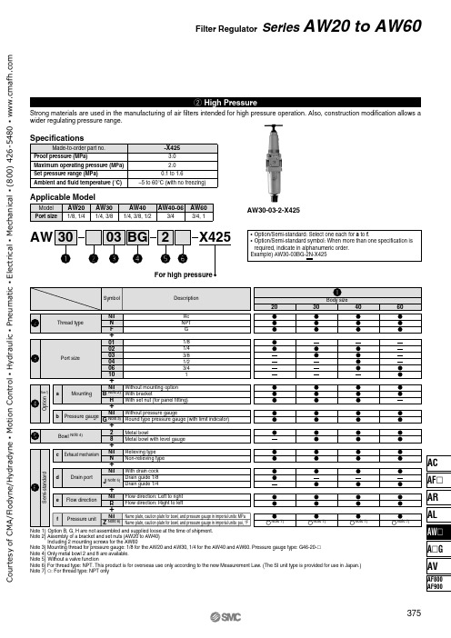
w High Pressure
Strong materials are used in the manufacturing of air filters intended for high pressure operation. Also, construction modification allows a wider regulating pressure range.
Note 5) Without a valve function Note 6) For thread type: NPT. This product is for overseas use only according to the new Measurement Law. (The SI unit type is provided for use in Japan.) Note 7) ć: For thread type: NPT only
-X425 3.0 2.0
0.1 to 1.6 –5 to 60°C (with no freezing)
Applicable Model
Model AW20 AW30 Port size 1/8, 1/4 1/4, 3/8
AW40 AW40-06 AW60
1/4, 3/8, 1/2
3/4
3/4, 1
AW30-03-2-X425
AW 30
03 BG 2
X425
• Option/Semi-standard: Select one each for a to f. • Option/Semi-standard symbol: When more than one specification is
required, indicate in alphanumeric order. Example) AW30-03BG-2N-X425
burkert宝德电磁阀选型样本

burkert宝德电磁阀选型样本BURKERT宝德电磁阀选型样本宝德专业化的流体控制系统六十多年来,Burkert一直致力于流体控制领域的产品和系统的研发、制造,如今Burkert已发展成一个拥有三千多名员工、在德国和法国拥有五家生产厂、在全球四十多个国家和地区设立了分公司的跨国集团,成为流体控制系统领域的全球领先者。
2/2-Way direct acting solenoid valve, for high0255 pressure and temperature, DN 1-6mm, 0 -100 bar2/2-Way Solenoid Valve Direct Acting for 2200 High Pressure2/2-Way High Pressure Solenoid Valve,5404 General Purpose, PN 1-50 bar, 1/2"-1" NPT,14-355 psi2/2-Way Solenoid Valve Servo Operated for 2400 High PressureAggressive mediaClick on the typenumber to view all available documents2/2 or 3/2 way direct acting flipper solenoidvalve with isolating diaphragm; ultra low dead 6124 volume; DN 0.6mm; vacuum up to 3bar; fastresponse time; 11mm width2/2 or 3/2 way direct acting rocker solenoid6126 valve with isolating diaphragm; DN 0.8mm;vacuum up to 10bar; 16mm width2/2 or 3/2 way direct acting rocker solenoid0127 valve with isolating diaphragm; DN 1.5 or1.6mm; 0 - 2bar; 16mm width2/2-Way Miniature Solenoid Valve with 0117 Isolating Diaphragm for AnalyticalApplications, G1/8, UNF 1/4-282/2 or 3/2 way direct acting rocker solenoid 6128 valve withisolating diaphragm; DN 2 or 3mm;vacuum up to 10bar; 22mm width2/2 or 3/2 way direct acting pivoted armaturesolenoid valve with isolating diaphragm; 0124 plastic body, 0#10 bar; DN 3 up to 5mm;G1/4#2/2 or 3/2 way direct acting pivoted armature 0330 solenoid valvewith isolating diaphragm; 0 -16 bar; DN 2 up to 4mm; G1/42/2 or 3/2 way direct acting pivoted armature 0331 solenoid valvewith isolating diaphragm; 0 #16 bar; DN 2 up to 4mm; sub-base mounting2/2 or 3/2 way direct acting pivoted armaturesolenoid valve with isolating diaphragm; direct 0121 acting; 0#4 bar; DN 4 up to 8mm; G1/4#,G3/8#2/2 or 3/2-Way Direct Acting Solenoid Valve 0131 for Aggressive Fluids, Plasic Body, DN10-20mm2/2-Way Servo assisted Solenoid Valve with 6642 plasit body (PVC) DN 10-13mm, 0,5-6 bar2/2-Way Servo-assisted Solenoid Valve,0142 Plastic Body, for Aggressive Fluids, DN15-50mmTop of Page PrintWater and other neutral mediaClick on the typenumber to view all available documents2/2 or 3/2 way direct acting flipper solenoidvalve with isolating diaphragm; ultra low dead 6124 volume; DN 0.6mm; vacuum up to 3bar; fastresponse time; 11mm width2/2 or 3/2 way direct acting rocker solenoid6126 valve with isolating diaphragm; DN 0.8mm;vacuum up to 10bar; 16mm width2/2-Way Miniature Solenoid Valve, General 6011 Purpose, 0-21 bar, 0-300 psi2/2 or 3/2 way direct acting rocker solenoid 6128 valve withisolating diaphragm; DN 2 or 3mm;vacuum up to 10bar; 22mm width3/2-way Flipper Solenoid Valve, direct acting, 6144 0 - 10 bar, Sub-base, for neutral gases andliquids2/2 or 3/2 way direct acting pivoted armature 0330 solenoid valve with isolating diaphragm; 0 -16 bar; DN 2 up to 4mm; G1/43/2Way Compact Solenoid Valve, General 6014 Purpose, DN 1.5-2.5mm, 0-16 bar, 1/16-5/64,0-72 psi, Direct acting2/2 or 3/2 way direct acting pivoted armature 0331 solenoid valve with isolating diaphragm; 0 #16 bar; DN 2 up to 4mm; sub-base mounting2/2-Way Compact Solenoid Valve, General 6013 Purpose, 0-10 bar, 0-145 psi, Direct actingMini, Small and Compact solenoid valves, 2/2 6027 and 3/2-way, G1/8 - G3/8 and sub-base,brass and stainless steel valve body2/2-way solenoid valve, pilot-controlled, for 6240 neutral liquids and gases, G1/4 - G3/8, 0-16bar, switches without differential pressure2/2-Way direct acting solenoid valve, Neutral 0256 gases and liquids,DN 2-12mm, 0 - 22 bar2/2-Way direct acting solenoid valve, for high 0255 pressure and temperature, DN 1-6mm, 0 -100 bar2/2-Way Servo-assisted Solenoid Valve, 6211 General Purpose, DN 10-20mm, 0.5-10 bar2/2-Way Servo-Assisted Solenoid Valve with 6212 optional Diagnosis Function for slightlycontaminated fluids, DN 10-20mm, 0,2-10 bar2/2-Way Servo-assisted Solenoid Valve, 6213 Linked System, General Purpose, DN10-40mm, 0-10 bar2/2-Way Modular Water Valve System, 6227 servo-assisted; variableand extendable,2/2-Way, DN 10-13, 1 up to 7 bar, 14-102 psi2/2-Way Plastic Solenoid Valve, 6228 Servo-assisted, General Purpose, G3/8-G1/2,0,5-10 bar2/2-Way Solenoid Valve, Servo-assisted, 5281 General Purpose, PN0.2-16 bar, 2.8-230 psi2/2-Way Solenoid Valve for Contaminated 5282 and Aggressive Fluids, General Purpose, PN0.2-10 bar, 2.8-230 psi2/2-Way Servo-assisted Solenoid Valve,0290 Linked System, General Purpose; DN 12-50mm3/2-Way Solenoid Valve Servo-assisted with 0340 Pivoted Armature Pilot, DN 8-40mm宝德电磁阀德国宝德电磁阀 BURKERT 德国宝德电磁阀宝德电磁阀东莞巴菲特自动化设备有限公司专业代理销售德国BURKERT电磁阀全部系列BURKERT产品大量使用于分析仪器、汽车制造、生物技术、化学、电子、能源、基因工程、半导体、化妆品、食品与饮料、啤酒工业、机械工程、医疗、医药卫生、纺织、包装、水(污水)处理、卫星、太空实验、核反应堆、深海探测等领域。
原装宝帝BURKERT电磁阀原理

原装宝帝BURKERT电磁阀原理原装宝帝BURKERT电磁阀原理BURKERT电磁阀就是以压缩空气为动力源,以气缸为执行器,并借助于电气阀门定位器、转换器、电磁阀、保位阀等附件去驱动阀门,实现开关量或比例式调节,接收工业自动化控制系统的控制信号来完成调节管道介质的流量、压力、温度等各种工艺参数。
气动调节阀的特点就是控制简单,反应快速,且本质安全,不需另外再采取防爆措施,下面我们将为大家介绍气动调节阀的工作原理与结构特点,如果你有需要的话可以跟我们一起来看一下。
BURKERT电磁阀工作原理:BURKERT电磁阀工作是以压缩空气作为动力源,以气动薄膜执行器为驱动机构,结合阀门定位器接收来自PLC或控制仪表输出的信号,实现自动控制调节阀开度,*的调节介质流量、压力、温度参数的给定值。
BURKERT电磁阀属于自动阀,工作时它自动接收信号,检测信号、反馈信号,自动调节介质参数。
根据调节效果可分为线性特性、抛物线特性三种。
该气动调节阀具有调节*度高、可调范围大、故障失气失信号时可弹簧复位开启或关闭。
BURKERT电磁阀结构特点:1、BURKERT电磁阀阀座采用卡入式构造防止了螺纹旋入式的缺陷,当压紧上盖时阀芯和阀座自动对中,而且装卸复杂方便,即便在严重腐蚀的状况下也能轻松的取出阀座,有利于维修和维护。
2、BURKERT电磁阀阀芯和阀杆采用一体式构造防止了插销式的缺陷,即便在高压差的状况下更能保证阀杆的波动性;3、在整个流量和特性范围内,均衡型和非均衡型阀塞,具有很高的切断密封功能;4、调节阀中采用均衡阀塞,可以接受比拟大的允许压差;宝德burkert电磁阀主要分类从原理上分为三大类:直动式电磁阀原理:通电时,电磁线圈产生电磁力把关闭件从阀座上提起,阀门打开;断电时,电磁力消失,弹簧把关闭件压在阀座上,阀门关闭。
特点:在真空、负压、零压时能正常工作,但通径一般不超过25mm。
分步直动式电磁阀原理:它是一种直动和先导式相结合的原理,当入口与出口没有压差时,通电后,电磁力直接把先导小阀和主阀关闭件依次向上提起,阀门打开。
KITZ Ball Valve - 产品说明书

BVP80, BVPS80 & BVE80 SeriesPneumatically & Electrically ActuatedBarstock Ball ValvesBVP80BVPS80BVE80Ball Valve - MATERIALS OF CONSTRUCTION BODY: Brass - ASTM B-16, or 316 Stainless Steel -ASTM A276BALL AND STEM: 316 Stainless SteelSEATS AND STEM SEAL: Glass Reinforced P .T.F.E.Ball Valve - CONNECTION / STYLE SIZESPipe / N.P .T.F.1/4” - 2”(Dryseal National Pipe Taper)Ball Valve - RATINGSTEMPERATURE: -50 F to 450 F(also see Pressure Temperature Chart)PRESSURE: 720 p.s.i. C.W.P . (Cold Working Pressure to 150 F)(also see Pressure Temperature Chart)VACUUM : 20 MicronSATURATED STEAM: 150 p.s.i.Ball Valve - FLOW CHARACTERISTICSThe approximate flow rate through a valve can be calculated as follows:where;Q = flow rate in gallons (U.S. Std.) per minute Cv = valve constantP = pressure drop across the valve in pounds per square inch G = specific gravity of the media of relative to waterNote: The values derived from the flow equation are for estimating purposes only. Product variances or systemic factors may alter actual performance.PQ = CvGBVP80, BVPS80 & BVE80 Series Ball Valvese z i S 4/18/32/14/314/1-12/1-12vC 5.55.5821236428021BVP80 & BVPS80 Series Pneumatic ActuatorsBVP80 & BVPS80 Pneumatic Actuators - MATERIALS OF CONSTRUCTIONBODY: Aluminium with P.T.F.E. Impre g nated Hard Anodized SufacesEXTERNAL HARDWARE: (Pinion Shaft, Driver, End Caps) 300 Series Stainless SteelEXTERNAL TRIM: 300 Series Stainless SteelPILOT VALVESPOOL: 18-8 Stainless Steel SEALS: Niltrile / FKM HARDWARE: 18-8 Stainless Steel COIL / BODY: GF Nylon / Polymide 66 BVP80 & BVPS80 Pneumatic Actuators -RATINGS / SPECIFICATIONSTEMPERATURE: -20 F to 350 FAIR SUPPLY: 60 - 125 psi air. Sufficient air delivery must be available at the actuator to ensure dependable operation. The following precautions should be observed: Air supply should be clean and free of moisture. When dirty or wet air is a problem; a filter / separator should be specified; these units are most effective when installed as closely as possible to the actuator. A filter, when used, should permit a minimum flow of 4 scfm at an upstream pressure of 60 psi. Eliminate severe restrictions to air flow (certain solenoid valves & fittings). The most restricted passage must have an area no smaller than .012 inches square, the area of 1/8” diameter orifice. If more than a single actuator is to be supplied by an individual pilot, the minimum passage requirement applies per actuator.TUBING: For short runs up to 5 feet 5/32” I.D. is suitable, 1/4” I.D. will serve up to 30 feet. For longer runs, use 3/8” I.D. or larger.DUTY CYCLE: 100%CYCLE TIME: (To Open or Close) Approximately 1/2 to 1 second** - Dependent upon actuator model, air pressure and deliveryAIR SUPPLY CONNECTION: 1/8” NPTELECTRICAL CONNECTION: Mini-DIN by Wire Strain ReliefELECTRIC: Standard 120VAC Coil;Wattage: 5Class: F Continuous DutyProtection: IP65 (with connector) Dust-tight, Water ResistantBVP80 & BVPS80 Pneumatic Actuators- MAINTENANCEOmega BVP70 & BVPS70 Series Pneumatic Actuators are designed to be maintenance free and normally are replaced vs. repaired.BVE80 Series Electric ActuatorsBVE80 Electric Actuator- MATERIALS OF CONSTRUCTIONENCLOSURE: Nylon Resin Cover, P.T.F.E. Coated Cast Aluminum BaseSHAFT: 18-8 Stainless SteelEXTERNAL TRIM: 300 Series Stainless SteelRATINGS / SPECIFICATIONSTEMPERATURE: 40 F to 150 FMOTOR: Reversing, Brushless, Capacitor-Run with Auto-Reset Thermal Overload Protection.GEAR TRAIN: Permanently Lubricated, Maintenance FreePOWER: 120VAC 50/60 Hz Single PhasePORTS: (2) 1/2” N.P.T. ConduitCYCLE TIME: 6 SecondsDUTY CYCLE: 1/4” - 1” Sizes;100%1-1/4” - 2” Sizes; 75%OVERRIDE: Manual - Fold Out Lever HandleMANUAL OVERRIDE OPERATIONThe push-button manual override system allows the user to easily disengage the electric drive gear train for manual operation of the actuator. All external power must be off prior to using the manual override feature. The actuator manual override handle can be used in the closed or open (lever extended) position to provide addi-tional leverage. To open the handle, pinch the Lever Release Buttons and pull up. Press down the manual override button (atop the center) and turn the handle to manually open or close the actuated valve assembly. T o reengage the drive train, release the override button and turn the handle until the manual override button ‘clicks’signaling the re-engagement of the drive train. The manual override lever handle can then be closed.Manual Override ButtonLever Release ButtonsBall Valve - INSTALLATION INSTRUCTIONSThe following serves as a guideline for those experienced in pipe joint makeup. Otherwise, services of a certified pipe fitter should be utilized for installation.1. Ensure that both the male pipe and female valve threads are free from dirt, debris and corrosion. Wire brushing of the male pipe threads is recommended to ensure a good metal-to-metal joint.2. Apply a good quality thread lubricant (pipe dope) on the male threads. Lubricant reduces friction when pulling up the pipe joint. Note, thread lubricant is not intended to seal the joint and will not compensate for poor quality male pipe or fitting threads.3. Turn the female valve threads onto the male pipe threads by hand. Upon free engagement of the threads, continue to turn the valve as far up as it will go (by hand). With the use of a wrench continue to tighten the valve onto the pipe. The pipe joint seal should occur within 1 to 3 turns after wrenching begins. Care should be taken not to exceed 3 turns in which damage to the threads can occur.4. The pipe joint should be tested for leakage to ensure the pipe joint has been achieved.Pneumatic Actuator - INSTALLATION INSTRUCTIONS1. Attached air supply to 1/8” NPT air inlet on integral pilot / solenoid valve.2. The coil is equipped with a DIN x Strain electrical connector. To wire the connector, remove the center mounting screw and, with a small screwdriver, pry the inner element from the body of the connector to expose the terminal blocks inside. Route the wire through the hub of the connector. Loosen the sealing nut and ensure the wire insulation passes through the rubber grommet inside the hub. Affix the wires to the appropriate termi-nal block. Retighten sealing nut to secure the wire and provide a seal.Electric Actuator - INSTALLATION INSTRUCTIONS1. Unlatch and open the override handle to access the handle nut. Remove nut with 3/4” wrench.2. Remove eight (8) socket head screws with 4mm hex wrench. Remove cover by pulling straight up.3. Route the wire to be terminated through conduit hub and up through the access space to the terminal block. Strip insulation back 1/4”, insert the stripped ends directly into the proper terminal clamps and tighten screws. All internal connections are labeled in the diagram, see Page 7.4. Attach grounding wire to green screw that is located on top of conduction bar.5. Verify that cover o-ring is properly seated in groove. Replace cover and screws.Electric Actuator - INSTALLATION INSTRUCTIONS (continued)120AC Wiring SchematicBall Valve - MAINTENANCEThe BVP80, BVPS80 & BVE80 Series utilizes our self compensating stem seal design. This design auto-matically compensates for wear as well as thermal expansion and contraction resulting in a leak tight, mainte-nance free, service life.Once the stem seal has worn beyond the compensation afforded by the Belleville springs adjustment of the stem nut may enable valve to be returned to service. Holding the ‘flats’ of the stem, tighten the stem nut until Belleville springs become fully compressed (flattened); the torque required to tighten the nut further increases sharply when this point is reached. Do not tighten the stem nut beyond this point to avoid damage of the stem seal.BVP80, BVPS80 & BVE80 Series Maintenance Instructions & DimensionsActuator - MAINTENANCEThe BVP80, BVPS80 & BVE80 Series actuators are maintenance free.BVP80 & BVPS80 Series DimensionsValve SizeActuator ModelApproximate Dimensions, InchesSpring Return SRDouble Acting DAAB DAB1SRCDE F SR F DA G H I J K L M N1/4, 3/8BVPS80Spring Return BVP80Double Acting1.46 1.00 1.37.312.75SR3.06DA4.76 4.66 4.51.42SR.27DA3.00 1.00 2.18 3.488.13 2.44.571/2 4.85 4.70 1.18 2.613/4 5.16 5.01 1.50 2.941 5.665.512.003.321-1/4 1.87 1.55 2.02.503.90SR4.50DA5.017.55 1.11 4.75 2.123.70 5.4611.-223.50.821-1/28.08 2.624.2528.433.004.57BVE80 Series Dimensionss e h c n I -s n o i s n e m i D e z i S e v l a V A B C D E F G HI J K 8/3&4/100.122.251.100.347.652.657.432.287.277.553.012/181.116.242.100.347.652.657.432.287.277.553.014/305.149.204.100.347.652.657.432.287.277.553.01149.123.326.100.347.652.657.432.287.277.553.014/1-121.207.367.108.442.752.657.432.287.277.558.012/1-126.252.420.208.442.752.657.432.287.277.558.01200.375.412.208.442.752.657.432.287.277.558.01M-4189/0512 11。
定时排水电磁阀
定时排水电磁阀马化工选用。
作为中国过程自动化仪表新技术的领先提供商,深圳万讯自控股份有限公司与国内诸多大型化工集团进行了多次合作,旗下成熟产品得到了用户的高度认可。
此次四川盛马化工股份有限公司(简称四川盛马化工)向万讯抛出了合作的"橄榄枝",投入在其新建的8万吨聚丙烯装置项目中。
四川盛马化工是经国家经贸委﹑国家工商局批准而保留的西南地区唯一地方石化企业,生产设备先进,采用了国际上先进的DCS集散控制系统,大大地提高了劳动生产率,达到了年加工原油40万吨,年产20万吨道路沥青的能力,同时,还生产出车用汽油、柴油、120#溶剂油、200#溶剂油、石油醚、石蜡、润滑油、工业用油等石化系列产品。
"施福乐麦索尼克"是万讯自控公司期下品牌,其主要产品为引进国外技术的调节阀、硬密封球阀、蝶阀等,并且在德国、意大利、无锡建立了专门的控制阀生产基地,采用欧洲先进控制阀技术,引进世界最先进的生产设备,构筑了自动化生产线。
该产品采用成熟的设计理念、先进的生产管理,严格按照当今世界主要标准制造及检验,制造的控制阀品质卓越,性能优异,具有流通能力大、压损小、密封好、噪音低、调节性能优、可调比大、运行可靠寿命长、结构紧凑等特点,深受石油、化工、电力等行业的青睐,而且经过这些行业企业长时间的各种性能测试,凭借其产品的高品质、高性能、高性价比达到了国际水准,完全能满足中国国情的需要,适合工业过程自动化控制。
万讯MVP智能阀门定位器是中国第一款具有防雷功能的定位器,与德国、美国企业联合开发的,采用首页>>产品中心>>ZBSF不锈钢电磁阀一、产品[不锈钢电磁阀]的详细资料:产品型号:ZBSF产品名称:不锈钢电磁阀产品特点:ZBSF系列全不锈钢电磁阀是工业过程自动化控制系统用执行器。
它在接受电控信号后能自动开启或关闭,实现对管道中的液体介质的通断或流量调节控制。
本系列电磁阀可广泛地应用于纺织、印刷、化工、塑料、橡胶、制药、食品、建材、机械、电器、表面处理等生产和科研部门以及浴室、食堂、空调等人们日常生活设施中。
美国ASCO电磁阀常用型号

美国ASCO电磁阀常用型号SCG531D001MS SCG551B401MO SCG551A066 SCG552A001 SCG551A002SCG551A001MS SCG551A017MS SCG552A017MS 238410-058-D272614-155-D 238410-058-D 238710-006-D 238610-158-D238610-032-D 238614-058-D 238510-034-D 272614-155-D272610-132-D 238714-006-D 238710-006-D 272610-058-D238210-058-D 064982-005-D EF8551A001MS EF8551A017MSEFG551H465 EFG551H466 EFG552G401MO 8210G94HT8316G64 57000014 57000103 HT8316G64HT8344G80 WSNF8327A112 8320G174 8210G009EF8210G201 EF8262G212 NF8327B002 8344G0728223G027 8263G205LT 8316G066 EF8320G174EF8320G176 8320G184 EF8320G184 8320G186EFG551H401 238610-058-D 099257-006-D WT8551A001MSEF8551A001MS SCG551A201 8551B401 EF8344G370WSNF8327B112 OFSF8263G206V NFG353A043 SCG353A05152100001 52100004 52100005 5200038012600024 60562300 34600137 JBEF8320G174SCG553A017 SCG551A419 18900001 NFB327A00252100008 52000008 35500335 3550033335500337 35500341 43004886 3550034635500347 35500338 SCG551A005MS SCG551A017MSSCG551A018MS SCG551A001MS SCG551A002MS EFG551H401MO54200001 12600008 NFB370A047 NF8327B112SCG531B001MS WSNF8551A421 SCB344A074 SC8344A074SCE370A008MS EFG551G401M0 8215B50 E238A204SCE238A004 SCXB320A178 EF8316G4 EF8210G48342G003 EFG551B401MO EF8316G54 EFG551H401MO8344B60M0 8355A082 HT8344G44 8210G15美国ASCO阿斯卡直动式电磁阀的分类:直动式电磁阀原理:通电时,电磁线圈产生电磁力把关闭件从阀座上提起,阀门打开;断电时,电磁力消失,弹簧把关闭件压在阀座上,阀门关闭。
- 1、下载文档前请自行甄别文档内容的完整性,平台不提供额外的编辑、内容补充、找答案等附加服务。
- 2、"仅部分预览"的文档,不可在线预览部分如存在完整性等问题,可反馈申请退款(可完整预览的文档不适用该条件!)。
- 3、如文档侵犯您的权益,请联系客服反馈,我们会尽快为您处理(人工客服工作时间:9:00-18:30)。
20 系列型号 H21 高压电磁阀 2 路常开阀
本阀采用针式风格密封。引脚被引导到孔口。为空气和其它无腐蚀性气体、水和油的使用。
•KEL-F 针式密封件; •板孔与密封针保证绝对密封; •结构简单,只有三个运动部件; •精密不锈钢阀杆。
产品型号: H21M7DGV H21M7DGV H21M7DCV H21M7DCV
•精密不锈钢阀杆。 •KEL-F 针密封件。 •孔板与密封针配合精度达到完美状态,确保零泄漏。 •结构简单,只有三个运动部件。 •隔爆型构造。
产品型号: EH21G7DCCM EH21H7DCCMG EH21J7DCCMG EH21K7DCCMG
EH21G7DCCM EH21H7DCCML EH21J7DCCML
机械特性: 10、 阀体材质:不锈钢(标准); 11、 内部组件:300 系列不锈钢; 12、 密封材质:KEL-F(标准)、其他弹性体材质选择; 13、 孔直径:1/32(具体型号参照上表); 14、 连接螺纹口径: 1/4 NPT; 15、 电气连接口径:防爆型管道连接 1/2NPT; 16、 使用寿命:≥500 万次,这取决于应用、维护等; 17、 单位产品重量:0.7KG; 10、产品尺寸:21.5 × 64.0 mm.
DC; 13、 额定功率:AC: 7.3W , DC : 9.5W; 14、 线圈建设:模压带接地三线(标准),H 级或内嵌式(选配)F 级; 15、 流速:高达 600CPM; 16、 反应时间:4-16 微秒; 17、 占空比:连续。
必须特定表明。 7、 电磁阀工作温度:标准常用型温度范围– 0°F (-18°C) to 221°F (105°C),根据
特定工况要求,可以满足更高或者更低工作温度要求,订购时必须咨询代表处; 8、 阀门极限压力:6000 PSI; 9、 反应动作时间:4 微秒。 10、 泄漏等级:泡沫等级。
电气特性: 6、 阀的电源电压:直流: 1.8 -- 265V DC; 7、 额定功率: DC : 9.5W; 8、 线圈建设:模压带接地三线(标准),H 级或内嵌式(选配)F 级; 9、 流速:高达 600CPM; 10、 反应时间:4-16 微秒; 11、 占空比:连续。
2500 1750 650
1500 500 100
3/64 1/16 3/32
0.041 0.065 0.100
EH23HH19DCCMG EH23JJ19DCCMG EH23KK19DCCMG
最大工作压力 液体(交流)
最大工作压力 液体(直流)
3000 1500 1000 300
3000 1500 500 100
EH21K7DCCML
高压防爆阀用于由于存在火灾或爆炸的危险现场,现场存在易燃气体或蒸气,易燃液体, 可燃粉尘或易燃纤维等物质,同时工艺过程要求高压作业,建议使用 EH21 系列防爆电磁阀, 从而提高安全保护水平。
EH21 系列为高压防爆电磁阀
电磁阀技术参数:
最大工作压力 (燃气)
最大工作压力 (液体)
20 系列型号 EH21 高压防爆型 2 路常开型
EH22 系列阀采用直动式工作原理,该系列阀由阀杆、密封针、磁芯、上下部密封件构成; 当线圈断电,通电时电磁线圈产生足够的电磁力把运动部件从阀座上下运动,阀门状态 发 生 变 化 ; 断 电 时 弹 簧 力 把 运 动 部 件 压 在 阀 座 上 , 阀 门 关 闭 。适用介质:空气、水、油 等无腐蚀性流体介质。
265V DC;
机械特性: 1、 阀体材质:300 系列不锈钢; 2、 内部组件:300 系列不锈钢; 3、 密封材质:Delrin®, Teflon®, Nylon, PEEK, Radel®, Ultem®, 303 不锈钢; 4、 孔直径:1/32(具体型号参照上表); 5、 连接螺纹口径:1/8 NPT 标准型或 1/4 NPT; 6、 电气连接口径:防爆型管道连接 1/2NPT; 7、 防护等级(UL&CSA 认证):Class I, Div 1, Group C and D – Class II, Div 1, Groups
以到 0°F (-18°C) to 150°F (65°C) ,根据特定工况要求,可以满足更高或者更低
工作温度要求,订购时必须咨询代表处; 3、 阀门极限压力:10000 PSI; 4、 反应动作时间:5 微秒。 5、 泄漏等级:零泄漏。
电气特性: 1、 阀的电源电压:交流 6 – 825 V AC 60 HZ. 5 – 720V AC 50 HZ 直流: 1.8 -2、 额定功率:AC: 7.3W , DC : 9.5W; 3、 线圈建设:模压带接地三线(标准),H 级或内嵌式(选配)F 级; 4、 流速:高达 600CPM; 5、 占空比时间:16 微秒。
美国 peter paul 高压电磁阀全集
美国 Peter Paul 中高压电磁阀,它的工作压力范围为: 1000 - 5000 PSI (6.5 – 35MPa )。广泛满足制 造医疗、实验室及仪器仪表等工业公司,满足多种流体介质的应用,如 02,C02、H2、HE 和压缩氮气等, 包括在各种应用的高压瓶装气体的装置使用的阀门。 美国 Peter Paul 中高压电磁阀根据目前特殊工业工况环境应用,推广防爆型高压电磁阀, 同时为了满足经济型结构设计,我们拥有微型高压防爆电磁阀。 美国 Peter Paul 中高压电磁阀产品特点: 1、Peter Paul 高压电磁阀阀体材质:不锈钢; 2、Peter Paul 高压电磁阀适用介质:水、气、油、蒸汽、燃气、腐蚀流体、甲醛等 7 3、Peter Paul 高压电磁阀工作温度范围:-40 — +260℃; 4、Peter Paul 高压电磁阀适用介质粘度:小于 80C St(大于时需定制); 5、Peter Paul 高压电磁阀防护性能:防水、防爆(Exd IICT5)、防腐; 6、Peter Paul 高压电磁阀控制方式:常开、常闭; 7、Peter Paul 高压电磁阀能提供更广泛电源电压:AC(交流) 6 - 825V AC 60 HZ. and 5 - 720V AC 50 HZ;
E, F, and G; Div 2, Groups C, D, E, F, and G; 8、 使用寿命:≥500 万次,这取决于应用、维护等; 9、 单位产品重量:0.5KG; 10、产品尺寸:21.5 × 64.0 mm.
20 系列型号 EH23 高压型电磁阀 三通常闭阀(EHX 直排)
使用 H22 系列的核心部件工艺,但比以前提供高得多的压力等级。作为一个常闭的 3 路阀 运作,经营者必须是交替通电和断电。施加压力的“IN”端口必须始终等于或大于在“排 气”端口的压力。适用于空气和其它无腐蚀性气体,水和油。
端口通径
1/32 3/64 1/16 3/32
阀门 CV 值
0.022 0.041 0.065 0.100
产品型号 (1/4NPT 管径连接)
EH23GG19DCCM EH23HH19DCCML EH23JJ19DCCML EH23KK19DCCML
使用环境: 6、 介质:空气和其他流体(建议过滤止 60 微米一下),水、油无腐蚀性的流体;,订货时