Agilent_频谱分析仪使用手册.
agilent信号分析仪操作步骤.doc
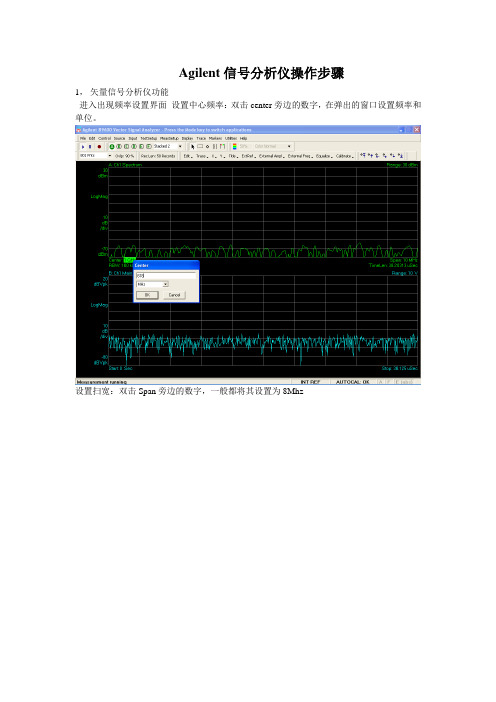
Agilent信号分析仪操作步骤1,矢量信号分析仪功能进入出现频率设置界面设置中心频率:双击center旁边的数字,在弹出的窗口设置频率和单位。
设置扫宽:双击Span旁边的数字,一般都将其设置为8Mhz设置range 单击range旁边的数字按向下键将波形图调至中心位置。
(-20dbm左右)选择菜单中的MeasSetup——Demodulator——Digital Demod。
进入数字信号分析功能。
选择图形个数查看星座图(双击左侧绿色方框,在弹出的对话框中选择constellation)查看I眼图(双击左侧绿色方框,在弹出的对话框中选择I-Eye)查看Q眼图(双击左侧绿色方框,在弹出的对话框中选择Q-Eye)进入扫频仪后界面如下设置起始频率,选择功能键Stop Freq设置终止频率,选择Center Freq设置中心频率。
按控制面板上的SPAN x Scale键出现如下界面,选择功能键Span设置扫宽按控制面板上的AMPTD y Scale键出现如下界面,选择功能键More 1of2选择Y Axis Unit 设置电平的单位。
按控制面板上的Trace Delecter键,选择功能键盘Trace Average后出现平滑的曲线。
按控制面板上的Input/Output键,选择功能键RF Input [AC,50欧],选择75欧。
按控制面板上的BW键,出现如下界面。
分别对RBW和VBW进行设置使曲线接近平滑,建议RBW设置为500-600khz左右,VBW设置为20khz左右,这样兼顾了曲线的平滑与扫频的速度。
按控制面板上的Maker 键后输入频率与单位,设置游标。
按控制面板上的Maker Function后可以选择有一定带宽范围的游标,出现如下界面。
选择功能键Band/Interval Density。
选择功能键Band Adjust调整宽度,如需关闭选择Maker Function Off。
Agilent N9343C手持频谱分析仪(HSA)数据手册说明书
Agilent N9343C Handheld Spectrum Analyzer (HSA)1 MHz to 13.6 GHz (tunable to 9 kHz)Data SheetField testing just got easier /find/hsaIf you are making measurements in the field, the Agilent N9343C handheld spectrum analyzer (HSA) makes your job easier. It's got the features you need for operating in tough field environments, and its measurement performance gives you confidence the job's been done right. The N9343C HSA lets you automate routine tasks to save time and ensure consistent results. Field testingjust got easier with the Agilent N9343C HSA.19812Definitions and requirementsThis data sheet contains specifications and supplemental information for Agilent N9343C handheld spectrumanalyzer. The differences between specifications, typical performance, and nominal values are described as follows.Definitions"Specifications" describe the performance of parameters covered by the product warranty and apply to temperatures ranging from -10 to 50 °C, unless otherwise noted.95th percentile values indicate the breadth of the popula-tion (> 2) of performance tolerances expected to be met in 95% of the cases with a 95% confidence, for any ambient temperature in the range of 20 to 30 °C. In addition to the statistical observations of a sample of instruments, these values include the effects of the uncertainties of external calibration references. These values are not warranted. These values are updated occasionally if a significant change in the statistically observed behavior of production instruments occurs."Typical" describes additional product performanceinformation that is not covered by the product warranty. Itmeasurement uncertainty.describe product performance that is useful in the applica-warranty.Your job just got easier:• Get the features you need in a field-ready instrument.• Gain confidence in your measurements with benchtop performance in a handheld instrument.• Innovative task planner (/find/taskplanner) reduces test setup time by 95%, delivers test automation and consistency, and makes it easy to capture test results, generate reports, and share task plans with others.Conditions required to meet specificationsThe following conditions must be met for the analyzer to meet its specifications.• The analyzer is within its calibration cycle.• Under auto couple control, except when Swp Time Rule is set to Accuracy.• Any analyzer that has been stored at a temperature range inside the allowed storage range but outside the allowed operating range must be stored at an ambient temperature within the allowed operating range for at least two hours before being turned on.• The analyzer has been turned on at least 30 minutes.CertificationAgilent Technologies certifies that this product met its published specifications at the time of shipment from the factory. Agilent Technologies further certifies that its cali-bration measurements are traceable to the United States National Institute of Standards and Technology (NIST), to the extent allowed by the Institute’s calibration facility, and to the calibration facilities of other International Standards Organization (ISO) members.Specifications31. RMS detector, trace averaging > 40, 0 dB input attenuation, input terminated 50 Ω, 1 kHz resolution bandwidth, normalized to 1 Hz, 20 to 30 °C.42. Reference level only affects the display not the measurement, so trace data markers do not cause additional errors in measurement results.567* ß is the ratio of frequency deviation to symbol rate (deviation/rate).8Visit /find/taskplanner for more information.3. For efficiency and convenience, RBW is restricted to be equal to or greater than 1 kHz and VBW is restricted to be equal to RBW.9/find/N9343C /find/hsa-videosAgilent Email Updates/find/emailupdates Get the latest information on the products and applications you select. Agilent Channel Partnersw w /find/channelpartners Get the best of both worlds: Agilent’s measurement expertise and product breadth, combined with channel partner convenience.For more information on AgilentTechnologies’ products, applications orservices, please contact your local Agilentoffice. The complete list is available at:/find/contactusAmericasCanada (877) 894 4414Brazil (11) 4197 3500Mexico 01800 5064 800United States (800) 829 4444Asia PacificAustralia 1 800 629 485China 800 810 0189Hong Kong 800 938 693India 1 800 112 929Japan 0120 (421) 345Korea 080 769 0800Malaysia 1 800 888 848Singapore 180****8100Taiwan 0800 047 866Other AP Countries (65) 375 8100Europe & Middle EastBelgium 32 (0) 2 404 93 40Denmark 45 70 13 15 15Finland 358 (0) 10 855 2100France 0825 010 700**0.125€/minuteGermany 49 (0) 7031 464 6333Ireland 1890 924 204Israel 972-3-9288-504/544Italy 39 02 92 60 8484Netherlands 31 (0) 20 547 2111Spain 34 (91) 631 3300Sweden 0200-88 22 55United Kingdom 44 (0) 131 452 0200For other unlisted countries:/find/contactusRevised: June 8, 2011Product specifications and descriptionsin this document subject to changewithout notice.© Agilent Technologies, Inc. 2011Printed in USA, November 1, 20115990-7499ENAgilent Advantage Services is committedto your success throughout your equip-ment’s lifetime. To keep you competitive,we continually invest in tools andprocesses that speed up calibration andrepair and reduce your cost of ownership.You can also use Infoline Web Servicesto manage equipment and services moreeffectively. By sharing our measurementand service expertise, we help you createthe products that change our world./quality/find/advantageservices。
Agilent 8590 E-Series 蔚蓝无线分析仪用户手册说明书
1981Agilent 8590 E-SeriesPortable SpectrumAnalyzersSpectrum Analysis by Agilent,Tailored Solutions to Meet Your Needs2Optional capability:•Separate closely spaced signals and increase sensitivity with narrow resolution bandwidths.•Measure digital transmitter power, timing, frequency, and modulation with digitaldemodulators for any of the major cellular and cordless formats.• Analyze “bursted” signals with time-gated spectrum analysis.• Assure EMI precompliance with quasi-peak detector.• Test components for scalar parameters with built-in tracking generators.•With group delay and amplitude flatness capability, you can do link analysis on…- Microwave radios - Satellites - CablesPLUS...there are over 20 other performance options you can choose from!Note the modulation quality of a GSM900 signalTransmission and reflection results for scalar testOptional hardware configurations…add performance and capability.Agilent Technologies has designed a series of Spectrum Analyzers that can be configured to your specific measurement needs.With the internal cardcage, circuit-card options can be inserted into any of four internal card slots toincrease your measurement capabilities.And should your needs change,your analyzer can adapt since most options are retrofittable.Flexible spectrum analysis PLUS...3Downloadable measure-ment personalities…add powerful measurement routines.For each application, Agilent offers a unique software program (provided on ROM-based memory cards), designed specifically for the 8590 E-series. Downloaded into analyzer memory, each meas-urement personality provides measurement setups, routines,and results specific to your appli-cation, as well as a user interface with terminology directly related to that application!Choose from a wide selection of measurement personalities:•RF Wireless Communications •Cable TV•EMI Precompliance •Microwave Links •Noise Figure •Lightwave •Broadcast TV •Digital Radio •Scalar Analysis•Customized personalities we create specifically for you!Benefits include:• Ease of use with one-button measurements• Complex tests are performed simply and quickly • Improved accuracy and repeatability over manual measurements•Results are operator independent• Save coding time with remotely programmable subroutines• Decreased training timePLUS…when you add them all together, you save time and money!EMI measurement compared to regulatory limitsApplication software EQUALS ... tailored solutions for you!Internal option cardcageCustomize your analyzer now or in thefuture with our plug-in, circuit-card options.Measurement Power Tailored for Your Success…4Softkey menus Array Operate your analyzer more easilywith related softkey functions.Zoom window (onscreen)Focus in on critical data quicklyand easily.Sturdy designTough and resilient: wherever youhave to go, your analyzer will, too.Internal option cardcageCustomize your analyzer now orin the future with our plug-in,circuit-card options.Built-in measurementsand advanced functionsAllow you to perform complexmeasurements with one-buttonease.I/O and parallel printer portExecute remote programs overGPIB or RS-232 and print testresults using the parallel printerinterface.Wide frequency rangesChoose from 9 kHz to 1.8 GHz,2.9 GHz, 6.5 GHz, 12.8 GHz,22 GHz, or 26.5 GHz.Card readerStore data on 128 Kbyte memorycards... and download measure-ment personalities.5Features and options summary6Performance summarySpecification summarySpecification18591E 8594E 8595E 8596E 8593EFrequency accuracy2, 3, 4±210 Hz±210 Hz±210 Hz±1.2 kHz±1.2 kHz Resolution bandwidth30 Hz to 3 MHz 30 Hz to 3 MHz30 Hz to 3 MHz 30 Hz to 3 MHz30 Hz to 3 MHz range4(10 Hz Nominal)(10 Hz Nominal)(10 Hz Nominal)Average noise level(30 Hz-RBW)4–130 dBm–127 dBm–127 dBm–127 dBm–129 dBm Optimum dynamic range(2nd/3rd Order)477 dB/90 dB78 dB/88 dB77 dB/86 dB102 dB/80 dB103 dB/81 dB Relative frequencyresponse±1.0 dB±1.0 dB±1.5 dB±2.0 dB±2.0 dBCalibrated displayrange70 dB70 dB70 dB70 dB70 dBAmplitude range4–130 dBm–127 dBm–127 dBm–127 dBm–129 dBmto +30 dBm to +30 dBm to +30 dBm to +30 dBm to +30 dBmPhase noise(30 kHz Offset, 1 GHz)–105 dBc/Hz–105 dBc/Hz–105 dBc/Hz–105 dBc/Hz–105 dBc/Hz7• Adjacent channel power (ACP)• Occupied bandwidth power • Third-order intercept• Percent AM• Signal bandwidth• Channel powerZoom in on signals with zoom window split screen displayJust one button calculates T.O.I. distortion products!• Fast-Fourier-Transform (FFT)allows quick analysis of the AMcomponents on the signal ofinterest.• Time-gated spectrum analysisobtains spectral details ofburst-modulated signals.sorted by frequency or amplitude.• And moreMeasure –1 to –80 dB bandwidths on signals.Now you can immediately identify amplitudeand frequency of top 10 peaks ... automatically!Built-in one-button measurement routines …save time, setup and training!Built-in functions…reduce analysis and troubleshooting time!89Automation and remote control…provide faster measurements through programmability!Reliability, service, and worldwide support network…provide solutions that lower your cost of ownership!Here’s what programming can do for you:• Automate routine measurement tasks• Increase testing throughput • Reduce complex measurements and calculate results• Improve measurement quality, accuracy, and repeatabilityTwo types of programs can beused to control the 8590 E-series spectrum analyzers:1. Remote programs can bedeveloped for controlling your spectrum analyzer from your computer when connected to either the GPIB or RS-232 interface of the analyzer; or,2. Downloadable programs (DLPs)can be developed to locallycontrol your spectrum analyzer.These programs, downloaded into your analyzer’s internal memory, provide customized measurement routinesassignedto analyzer softkeys.You can program your analyzer to perform repetitive tasks — and that saves measurement time andmoney! Use over 200 fully documented programming commands to develop programs that specificallymeet your needs, or, call upon expert application engineers — available worldwide — to write programs for you.All 8590 E-series spectrum analyzers…• Are manufactured in an ISO 9001 registered facility to exacting standards…and come with optional calibration certificates traceable to national standards; and• Comply with U.S. military MIL-T-28800 class 5 environmental standards ... and that meansreliable, accurate performance in portable applications; and • Contain built-in self-tests and calibration routines to ensure measurement integrity; and • Are delivered with the most thorough user, calibration and service documentation in the industry and with complete calibration and serviceavailable at 27 Agilent locations worldwide.Agilent’s technical professionals…• Are a phone call away to provide technical application assistance;• Are available to provide local user training; and,•Are available to provide factory service training to support your internal calibration and service needs.10Research and developmentShorten your development time by equipping your engineering team with the analysis tools they need to optimize their designs.• Speed-up design trouble-shooting with built-in,one-button measurementroutines. For example,Third-Order-Intercept,Adjacent Channel Poweror one of Agilent’s measure-ment personalities.• Use the 8590-series analyzerswith EEsof’s MDS Modelingand Simulation Software toverify breadboard performance,as compared to circuitsimulations.•Minimize costs associated with buying additional instruments and adding bench space by leveraging the 8590 E-series scalar and noise figure capabilities.ManufacturingEnhance your production line throughput with analyzersdesigned for measurement speed in automated test systems and for ease-of-use in individually operated test stations.• Reduce test costs and increase throughput, accuracy, andrepeatability with built-in routines.Perform “go/no-go” testing with features like limit lines andeasily interpreted PASS/FAILmessages.•Automate your testing toimprove throughput andaccuracy by programming youranalyzer to perform repetitivemeasurement tasks.•Execute programs from theanalyzer’s memory or your PC.• Save money on futureequipment purchases whenproduction line requirementschange by retrofitting newcapabilities into your8590 E-series.Field service, installation and signal surveillanceTake the power and flexibility of the 8590 E-series with you wherever you need on-site analysis.• Carry less equipment with you into the field by equipping your analyzer with optional, multi-performance capabilities, such as group delay or on-screen TV picture.• Store test results in the field on compact, rugged, solid state memory cards with automatic time/date stamps.• Record screen data with VCR for long term signal monitoring;limit lines provide signal activity alerts.• Field accessories include an external battery pack CRT sun shield, protective front cover,operating/carrying case, nylon backpack, and transit case.Application specific literatureLiterature Number 8590 C/E/L and EM Series Configuration Guide 5963-6858E 8590L and 8592L Product Overview 5962-7275E 8590 E-series Technical Specifications5963-6909EManufacturing, field and moreGeneral purpose spectrum analysisThis easy-to-use tool provides a broad range of testing capability across a wide variety of applica-tions. You can display relationships between power, frequency, and time with over 200 built-in measurement functions!Note:For lowest cost, general purpose RF/MW spectrum analysis, see the 8590 L-series. Contact your Agilent representative for more information.Customize your transmitter testingFor the design, manufacturing, installation, or service of digital RF wireless communications equipment, the 8590 E-series spectrum ana-lyzer with measurement personality is the tool you need.Quick, easy, one-buttontransmitter measurements•Customized transmitter testsbased on industry standardsfor GSM, DCS1800, NADC-TDMA, CDMA, PDC, DECT,CT2-CAI, and PHS•Fast, easy, one-button trans-mitter measurement person-Additional features make yourmeasurement easier•Automatic tuning by channelnumber• Pass/Fail messages• Continuous measurement modefor real-time equipmentadjustments and troubleshooting• Results displayed in numericIQ diagram of a NADC-TDMA signalChannel power of a CDMA signalMeasurement Personality Literature Number5966-3803E5962-6217E5963-9971E5091-7761E5963-9969E5964-0110EDigital RF wireless communicationsThe measurementsyou need in one convenient packageWhen it comes to installing and maintaining a microwave radio system, you can select the test solution that exactly meets your needs. Choose from personalities, options and system configurations created specifically for those who install and maintain microwave radios of all types—from routine maintenance of low capacity links to installation and commissioning of high capacity systems.Digital radio measurements•For low-capacity systemmaintenance, the 85713ADigital Radio MeasurementsPersonality adds mask com-parison, mean-power-level,frequency response and transientmeasurement capabilities to thestandard Spectrum Analyzer.The personality includesstandard FCC, UK and FRGagency masks, as well as theability to create custom masks.•For higher capacity systems,group delay and amplitudeflatness measurements may berequired. The 11770A LinkMeasurements Personality, inconjunction with Option 111in the Spectrum Analyzer, usesthe analyzer and its trackinggenerator as receiver andtransmitter respectively.Two independent analyzerscan be used for end-to-endand frequency translationmeasurements over the entirefrequency range of the generatoroutput and analyzer input.• The 11758V Digital Radio Testsystem provides comprehensivemeasurement capability forinstallation and maintenanceof high capacity systems. Thesystem is based on a specially-configured 8593E SpectrumAnalyzer and the 11758BMultipath Fading Simulator.Available options include:-group delay- a microwave source forantenna return loss measure-ments- a fully configured system formicrowave satellite systemgroup delay measurementsbased on a synthesizedsweeper.Factory integrated specialconfigurations are available.Amplitude and group delay response foradjusting transmission networksLiterature NumberTools for Digital Microwave Radio Installation & Maintenance (AN 355-1)5962-9920E5091-4651E11770A Link Measurements Personality Data Sheet5091-4652E Digital radioDifferential gain and phase video measurements made to world wide standards.Your portable, single box tester for both RF and video measurementsSave time in cable TV manufacturing and maintenance with fast one-button measurement routines. Agilent Technologies offers two solu-tions for the cable TV industry; the 8590 E-series spectrum analyzer with the 85721B cable TV measurement personality for manufacturers,or the CaLan 8591C cable TV analyzer for cable TV operators. TheCaLan 8591C includes many 8590 E-series analyzer options specifically for cable TV testing!Featuresand options include:•Dedicated Cable TV measure-ments which provide one-button,non-interfering RF and video tests.•Automated compliance testing to FCC regulations and world-wide standards.• System tests for installation, maintenance, troubleshooting and performance monitoring.•Five frequency ranges, 1.8 GHz to 22/26.5 GHz (8590 E-series).• 75-ohm input that matches analyzer to trunk cable or other 75-ohm environments.• Flexible hardware and software architecture for easy upgrading. • 75-ohm pre-amp for low-level carrier-to-noise measurements.• Dual interfaces; a parallel printer port with either an GPIB or RS-232 port.• Television picture capability to verify subscriber complaintsWith your analyzer, you can determine…RF measurements:• Automatic tuning to cable TV and broadcast carriers.• Visual and aural carrier levelsand frequencies• System channel survey • Depth of modulation • Crossmodulation• Aural and FM broadcast carrier deviation • Carrier-to-noise ratio• In-channel frequency response • Hum and low frequency disturbances• System frequency response • Distortion (CSO/CTB)Video measurements:• Differential gain • Differential phase• Chrominance-to-luminance delay inequalityAdd the Agilent CaLan 85921B FCC report generator for moving test data from your analyzer to your PC and providing FCC proof-of-performance reports!Cable TVThe design cycleThere’s no better time than early in the design cycle to solve EMC problems—problems that could prove very costly to correct, even to the point of delaying a new product’s introduction — prob-lems you can identify and analyze at the push of a button with 8590 E-series spectrum analyzers.• Use your 8590 E-series analyzer with the EMC measurement personality (85712D), antennas and accessories to search for radiated emissions.•Measure conducted emissions with the LISN and accessories. • Using the close-field probe set (11945A Option E51), pinpoint emissions, make design changes and compare the results.Selected featuresand options include:• Automated, one-button EMCprecompliance measurements.• Fast setup of all EMC measure-ment system parameters from arange of setup libraries.• Measure the quasi-peak, averageand peak levels of up to 20 signalsautomatically.• Enhanced measurementaccuracy with built-in transduceramplitude corrections.• Built-in tracking generator forshielding effectiveness andimmunity testing.• System diagnostic tools to quicklyisolate, classify and record EMCdesign problem spots.• A complete line of EMCtransducers and accessories toperform EMI measurements tomeet your needs. Avoid costly EMC compliance delaysThe 8590 E-series spectrum analyzer and 85712D EMC measurementpersonality, options and accessories give you EMC precompliance anddiagnostic capabilities. For dedicated EMI users, Agilent recommendsthe 8590EM series EMC analyzers.EMC precomplianceApplication specific literature Literature Number8590EM Series EMC Analyzers andPrecompliance Systems5964-6091EEMC Accessories Catalog5966-1188Eyou’re not forced to purchase multiple instruments —now you can com-bine the functions of a spectrum analyzer, noise figure meter, and scalaroptional 1.8/2.9 GHz built-in tracking…add the 5630A scalar test set for:• Simultaneous transmission/reflection• Built-in RF bridges• Ease of set-up and useMeasure swept noise figure and gain ofan amplifierOrdering informationSpectrum analyzers8591E RF Spectrum Analyzer (9 kHz to 1.8 GHz)8594E RF Spectrum Analyzer (9 kHz to 2.9 GHz)8595E RF Spectrum Analyzer (9 kHz to 6.5 GHz)8596E MW Spectrum Analyzer (9 kHz to 12.8 GHz)8593E MW Spectrum Analyzer (9 kHz to 22/26.5 GHz)Options, measurement personalities, and accessoriesFor complete ordering and compatibility information on available options, retrofit kits, and measurement personalities,please see the 8590 C/E/L and EM Series Configuration Guide, Literature Number 5963-6858E.Literature reference indexLiterature General purpose information Number 8590L and 8592L Product Overview5962-7275E 8590 E-Series Technical Specifications5963-6909E 8590 C/E/L and EM Series Configuration Guide5963-6858EProduct feature briefsAnalog+ Display5091-4054E Transmitter Power Measurements (ACP, OBW)5091-4055E Zoom Window5091-4051E Measuring AM with FFT5091-4049E Time-Gated Spectrum Analysis5091-4053E Editing Keyboard5091-4048E Marker and Peaks Table5091-4050E Third Order Intermodulation, N dB Bandwidth and Percent AM 5091-4052E Product notesTime-Gated Spectrum Analysis (8590-2)5952-3685 Analog+ Display 5091-2364E Maximizing Accuracy in Noise Figure Measurements (85719A-1)5091-4801E Application notesSpectrum Analysis Basics (150)5952-0292 Amplitude and Frequency Modulation (150-1)5954-9130Agilent Technologies’ Test and Measurement Support, Services,and AssistanceAgilent Technologies aims to maximize the value you receive, while minimizing your risk and problems. We strive to ensure that you get the test and measurement capabilities you paid for and obtain the support you need. Our extensive support resources and services can help you choose the right Agilent products for your applications and apply them successfully. Every instrument and system we sell has a global warranty. Support is available for at least five years beyond the production life of the product. Two concepts underlie Agilent’s overall support policy: “Our Promise” and “Your Advantage.”Our PromiseOur Promise means your Agilent test and measurement equipment will meet its advertised performance and functionality. When you are choosing new equipment, we will help you with product information, including realistic performance specifica-tions and practical recommendations from experienced test engineers. When you use Agilent equipment, we can verify that it works properly, help with product operation, and provide basic measurement assistance for the use of specified capabilities, at no extra cost upon request. Many self-help tools are available.Your AdvantageYour Advantage means that Agilent offers a wide range of additional expert test and measurement services, which you can purchase according to your unique techni-cal and business needs. Solve problems efficiently and gain a competitive edge by contracting with us for calibration, extra-cost upgrades, out-of-warranty repairs, and on-site education and training, as well as design, system integration, project management, and other professional engineering services. Experienced Agilent engineers and techni-cians worldwide can help you maximize your productivity, optimize the return on investment of your Agilent instruments and systems, and obtain dependable measure-ment accuracy for the life of those products. For more assistance with your testand measurement needs go to/find/assist Copyright © 2000 Agilent Technologies Printed in USA 7/005963-6908E。
Agilent频谱分析仪基本操作简介
Agilent頻譜分析儀基本操作簡介
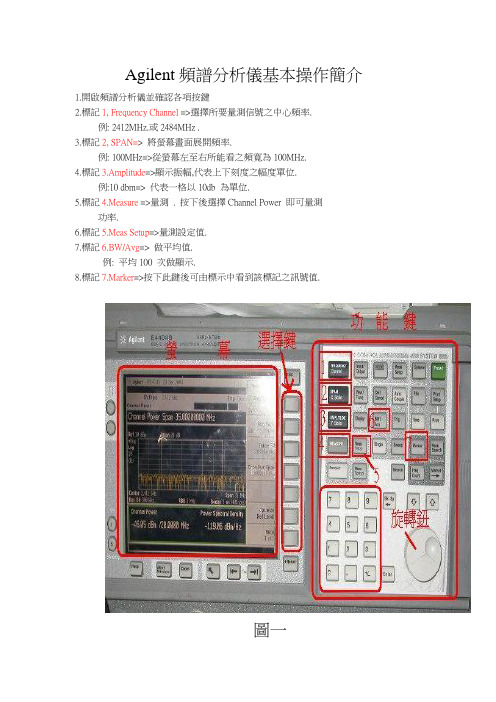
1.開啟頻譜分析儀並確認各項按鍵
2.標記1, Frequency Channel =>選擇所要量測信號之中心頻率.
例: 2412MHz.或2484MHz .
3.標記2, SPAN=> 將螢幕畫面展開頻率.
例: 100MHz=>從螢幕左至右所能看之頻寛為100MHz.
4.標記3.Amplitude=>顯示振幅,代表上下刻度之幅度單位.
例:10 dbm=> 代表一格以10db 為單位.
5.標記4.Measure =>量測 . 按下後選擇Channel Power 即可量測
功率.
6.標記5.Meas Setup=>量測設定值.
7.標記6.BW/Avg=> 做平均值.
例: 平均100 次做顯示.
8.標記7.Marker=>按下此鍵後可由標示中看到該標記之訊號值.
圖一
例如﹕需要量測2412Mhz的波形及POWER大小
0.先按下標記1位置並以數字鍵按21412後選MHz(如圖二紅框右方之按鍵). 即調整好頻
率.(圖二)
圖二
1.按下標記2即以數字鍵按100後按MHz(紅框右方按鍵) 即調整
好頻寛. (圖三)
圖三
12.按下標記3以數字鍵按20後選dBm位置按鈕. (圖四)
圖四13.按下標記4選擇Channel Power 以量測功率增益. (圖五)
圖五
14.Channel Power 後, 先選取Integ BW 按下20MHz (量測之頻寛20MHz),再選Chan Pwr
Span 選擇35MHz .(代表由蛍幕左方至右方僅35MHz 頻寛.
(圖六)
15.接上待測品後量取功率增益。
Agilent_E4402B_频谱分析仪使用说明
Agilent E4402BESA-E Series Spectrum Analyzer使用方法简介宁波之猫2009-6-17目录3.1 Control(控制)功能区 ...................................................................................3.1.3 Amplitude Y Scale ..................................................................................1简介Agilent ESA-E系列是能适应未来需要的Agilent中性能频谱分析仪解决方案。
该系列在测量速度、动态范围、精度和功率分辨能力上,都为类似价位的产品建立了性能标准。
它灵活的平台设计使研发、制造和现场服务工程师能自定义产品,以满足特定测试要求,和在需要时用新的特性升级产品。
该产品采用单键测量解决方案,并具有易于浏览的用户界面和高速测量的性能,使工程师能把较少的时间用于测试,而把更多的时间用在元件和产品的设计、制作和查错上。
2.面板2.1 操作区1.观察角度键,用于调节显示,以适于使用者的观察角度。
2.Esc键,可以取消输入,终止打印。
3.无标识键,实现左边屏幕上紧挨的右边栏菜单的功能。
4.Frequency Channel(频率通道)、Span X Scale(扫宽X刻度)和AmplitudeY scale(幅度Y刻度)三个键,可以激活主要的调节功能(频率、X轴、Y 轴)并在右边栏显示相应的菜单。
5.Control(控制)功能区。
6.Measure(测量)功能区。
7.System(系统)功能区。
8.Marker(标记)功能区。
9.软驱和耳机插孔。
10.步进键和旋钮,用于改变所选中有效功能的数值。
11.音量调节。
12.外接键盘插口。
13.探头电源,为高阻抗交流探头或其它附件提供电源。
Agilent 安捷伦8590B 8591A 8593A 8592B8595A频谱分析仪操作手册

ErrataTitle & Document Type: 8590B/8591A/8593A/8592B/8594A/8595A SpectrumAnalyzer Operation ManualManual Part Number: 08590-90001Revision Date: July 1978About this ManualWe’ve added this manual to the Agilent website in an effort to help you support your product. This manual provides the best information we could find. It may be incompleteor contain dated information, and the scan quality may not be ideal. If we find a bettercopy in the future, we will add it to the Agilent website.HP References in this ManualThis manual may contain references to HP or Hewlett-Packard. Please note that Hewlett- Packard's former test and measurement, life sciences, and chemical analysisbusinesses are now part of Agilent Technologies. The HP XXXX referred to in this document is now the Agilent XXXX. For example, model number HP8648A is now model number Agilent 8648A. We have made no changes to this manual copy.Support for Your ProductAgilent no longer sells or supports this product. You will find any other availableproduct information on the Agilent Test & Measurement website:Search for the model number of this product, and the resulting product page will guideyou to any available information. Our service centers may be able to perform calibrationif no repair parts are needed, but no other support from Agilent is available.。
agilent信号分析仪操作步骤.doc
Agilent信号分析仪操作步骤1,矢量信号分析仪功能进入出现频率设置界面设置中心频率:双击center旁边的数字,在弹出的窗口设置频率和单位。
设置扫宽:双击Span旁边的数字,一般都将其设置为8Mhz设置range 单击range旁边的数字按向下键将波形图调至中心位置。
(-20dbm左右)选择菜单中的MeasSetup——Demodulator——Digital Demod。
进入数字信号分析功能。
选择图形个数查看星座图(双击左侧绿色方框,在弹出的对话框中选择constellation)查看I眼图(双击左侧绿色方框,在弹出的对话框中选择I-Eye)查看Q眼图(双击左侧绿色方框,在弹出的对话框中选择Q-Eye)进入扫频仪后界面如下设置起始频率,选择功能键Stop Freq设置终止频率,选择Center Freq设置中心频率。
按控制面板上的SPAN x Scale键出现如下界面,选择功能键Span设置扫宽按控制面板上的AMPTD y Scale键出现如下界面,选择功能键More 1of2选择Y Axis Unit 设置电平的单位。
按控制面板上的Trace Delecter键,选择功能键盘Trace Average后出现平滑的曲线。
按控制面板上的Input/Output键,选择功能键RF Input [AC,50欧],选择75欧。
按控制面板上的BW键,出现如下界面。
分别对RBW和VBW进行设置使曲线接近平滑,建议RBW设置为500-600khz左右,VBW设置为20khz左右,这样兼顾了曲线的平滑与扫频的速度。
按控制面板上的Maker 键后输入频率与单位,设置游标。
按控制面板上的Maker Function后可以选择有一定带宽范围的游标,出现如下界面。
选择功能键Band/Interval Density。
选择功能键Band Adjust调整宽度,如需关闭选择Maker Function Off。
8563EC使用手册
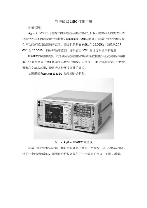
频谱仪8563EC使用手册一、频谱仪简介Agilent 8563EC 是便携式的彩色显示微波频谱分析仪,提供昂贵的更大台式分析仪才具备的测量能力和特性。
8563EC将8560EC系列RF频谱分析仪的优良特性和功能扩展到微波频率范围。
该分析仪具有 9kHz 至 26.5GHz(预选从2.75 GHz 至 26.5GHz)的标准频率范围,并具有至 30Hz 的可选低端频率覆盖。
8563EC的镜频增强、双平衡谐波混频器的噪声系数性能与基波混频前端相似。
它使用坚固的MIL机箱兼具优异的相噪、灵敏度、1Hz分辨率带宽、合成型调谐和宽动态范围,能适应各种环境条件的要求。
如图所示为Agilent 8563EC 微波频谱分析仪。
图 1 :Agilent 8563EC 频谱仪频谱分析仪就像示波器一样是用来观察信号的一个基本工具。
其中示波器提供了一个时域的窗口,而频谱分析仪则提供了一个频率的窗口,如图2所示。
图2二、基本操作介绍首先打开仪器:1、按‘LINE’键,打开频谱仪。
2、频谱仪经过半分钟来完成一系列的自我检测和调节程序。
完成后,屏幕上会出现分析仪型号和软硬件结合数据(如,890802 显示为1989年8月2日)。
如果你在任何时候需要了解安捷伦的服务技术或你的分析仪有任何的问题,它将对于了解软硬件数据从而得到更多准确的信息很有帮助。
3、允许分析仪有5分钟的预热时间。
4、在后面将给出参考标准的校准调节程序。
5、完成微量调准程序,从而优化显示区域。
6、通用接口总线地址可能由于细微的操作而被改变。
·频谱仪的工作范围:幅度范围 -148dBm到+30dBm频率范围 9kHz到26.5GHz·基本测量:一个基本测量包括调谐频谱仪使在屏幕上出现一个信号,然后使用‘marker’对其频率和幅度进行测量。
我们可以经过四个简单的步骤完成对一个输入信号的测量。
1、设置中心频率;2、设置频率范围;3、激活‘marker’;4、设置幅度。
Agilent-N9020A使用说明书
功能测试安捷伦科技N9020A MXA 操作手册1功能测试功能测试是对各种仪器参数的测试,这些参数对分析仪是否正常工作具有高度的信心。
建议在进货检验或修理后检查分析仪的运行情况。
测量不确定度分析不适用于功能测试,分析仪应根据比公布规范更宽的限值进行检查。
功能测试旨在使用最小的测试设备,测试分析仪在分析仪规范规定的温度范围内运行的分析仪。
如果测试未通过,则必须运行性能验证测试以确定是否存在问题。
功能测试与性能验证功能测试使用最少的测试设备来检查比性能验证测试小得多的参数范围(以及每个参数的有限数据点)。
功能测试使用比公布规范更宽的限值;测量不确定度分析不适用于功能测试。
注意如果功能测试未通过,则必须运行性能验证测试以确定是否存在问题。
性能验证测试涵盖了广泛的仪器参数,并提供了仪器符合公布规范的最高置信水平。
这些测试可能很耗时,需要大量的测试设备。
本文件内容本章包括以下内容:•“在进行功能测试之前”,(首先要做什么)。
•“测试设备”(所有测试所需的设备清单)。
随后的章节描述了以下功能测试:•“显示平均噪声级(DANL)”•“频率读数精度”•“二次谐波失真(SHD)•“50 MHz振幅精度”•“50 MHz振幅精度”•“频率响应(平坦度)”•“频率响应(平坦度)前置放大器开启”•“刻度保真度”•“BBIQ输入频率响应(仅BBA选项),每个功能测试包括:•测试限值(合格/不合格标准)•测试说明•测试所需的设备•显示如何连接设备的图•逐步说明•记录测量结果的一个或多个表格在执行功能测试之前1.确保你有合适的测试设备。
2.打开被测单元(UUT)并使其预热(根据仪器规范中的预热要求)。
3.为所需的测试设备留出足够的预热时间(有关预热规范,请参阅单独的仪表文档)。
4.确保分析仪的频率参考设置为内部:a、按,键。
输入/输出更多频率参考输入b、如果软键不显示,请按软键并选择。
内部频率参考内部频率参考5.在仪器预热后,执行自动校准程序:按。
Agilent 4395A 网络 频谱 阻抗分析仪数据手册说明书
Network Measurement1.At relative to 0 dBm output, 50 MHz,23 °C ±5 °C /HP-Agilent-4395A-Spectrum-Network-Analyzer.aspx To buy, sell, rent or trade-in this product please click on the link below:2Network MeasurementcontinuedReceiver CharacteristicsInput characteristicsFrequency range . . . . . . . . . . . . . . . . . . . . . . . . . . . . . . . . . . . . . . . . . . .10 Hz to 500 MHzInput attenuator . . . . . . . . . . . . . . . . . . . . . . . . . . . . . . . . . . . . . . . . .0 to 50 dB, 10 dB stepFull scale input level (R, A, B)Attenuator setting (dB) Full scale input level0–10 dBm100 dBm20+10 dBm30+20 dBm40+30 dBm50+30 dBmIF bandwidth (IFBW)2, 10, 30, 100, 300, 1 k, 3 k, 10 k, 30 kHzNote: The IFBW should be set to less than 1/5 of the lowest frequency inthe sweep range.Noise level (referenced to full scale input level, 23 °C ±5 °C)at 10 Hz ≤frequency < 100 Hz, IFBW = 2 Hz . . . . . . . . . . . . . . . . . . . . . .–85 dB (SPC)at 100 Hz ≤frequency < 100 kHz, IFBW = 10 Hz . . . . . . . . . . . . . . . . . . . . . . . . .–85 dBat 100 kHz ≤frequency, IFBW = 10 Hz . . . . . . . . . . . . . . . . . . . . . . . . . . . . . .-–115 dBInput crosstalkfor input R + 10 dBm input, input attenuator: . . . . . . . . . . . . . . . . . . . . . . . . . . . . .20 dBfor input A, B input attenuator: . . . . . . . . . . . . . . . . . . . . . . . . . . . . . . . . . . . . . . . . .0 dBat < 100 kHzR through A, B . . . . . . . . . . . . . . . . . . . . . . . . . . . . . . . . . . . . . . . . . . . . . .< –100 dBothers . . . . . . . . . . . . . . . . . . . . . . . . . . . . . . . . . . . . . . . . . . . . . . .< –100 dB (SPC)at ≥100 kHzR through A, B . . . . . . . . . . . . . . . . . . . . . . . . . . . . . . . . . . . . . . . . . . . . .< –120 dBothers . . . . . . . . . . . . . . . . . . . . . . . . . . . . . . . . . . . . . . . . . . . . . . .< –120 dB (SPC)Source crosstalk (for input A, B)(typical for input R)at + 10 dBm output, < 100 kHz, input attenuator: 0 dB . . . . . . . . . . . . . . . . .< –100 dBat + 10 dBm output, ≥100 kHz, input attenuator: 0 dB . . . . . . . . . . . . . . . . .< –120 dBMultiplexer switching impedance changeat input attenuator 0 dB . . . . . . . . . . . . . . . . . . . . . . . . . . . . . . . . . . . . . . . .< 0.5% (SPC)at input attenuator 10 dB and above . . . . . . . . . . . . . . . . . . . . . . . . . . . . . .< 0.1% (SPC)Connector . . . . . . . . . . . . . . . . . . . . . . . . . . . . . . . . . . . . . . . . . . . . . . . . . . . .Type-N femaleImpedance . . . . . . . . . . . . . . . . . . . . . . . . . . . . . . . . . . . . . . . . . . . . . . . . . . . .50 ΩnominalReturn lossInput attenuator0 dB10 dB20 dB to 50 dB10 Hz ≤frequency < 100 kHz25 dB125 dB125 dB1100 kHz ≤frequency ≤100 MHz25 dB125 dB25 dB1100 MHz < frequency15 dB115 dB15 dB1Maximum input level+30 dBm (at input attenuator: 40 dB or 50 dB)Maximum safe input level+30 dBm or ±7 Vdc (SPC)1.SPC34Absolute amplitude accuracy (R, A, B)at –10 dBm input, input attenuator:10 dB, frequency ≥100 Hz, IFBW ≤3 kHz, 23 °C ±5 °C, . . . . . . . . . . . .< ±1.5 dB Ratio accuracy (A/R, B/R) (typical for A/B)at –10 dBm input, input attenuator:10 dB, IFBW ≤3 kHz, 23 °C ±5 °C, . . . . . . . . . . . . . . . . . . . . . . . . . . . . . . .< ±2 dB Dynamic accuracy (A/R, B/R) (typical for A/B)Input level Dynamic accuracy 1(relative to full scale input level)frequency ≥100 Hz 0 dB ≥input level > –10 dB ±0.4 dB –10 dB ≥input Level ≥–60 dB ±0.05 dB –60 dB > input level ≥–80 dB ±0.3 dB –80 dB > input level ≥–100 dB ±3 dB Figure 1-1. Magnitude dynamic accuracy Residual responses . . . . . . . . . . . . . . . . . . . . . . . . . . . . . . . . . . .< –80 dB full scale (SPC)Trace noise (A/R, B/R, A/B)at 50 MHz, both inputs: full scale input level –10 dB, IFBW = 300 Hz . . . . . . . . . . . . . .< 0.005 dB rms (SPC)Stability (A/R, B/R, A/B) . . . . . . . . . . . . . . . . . . . . . . . . . . . . . . . .< ±0.01 dB/°C (SPC)Phase characteristics Measurements format . . . . . . . . . . . . . . . . . . .Standard format, expanded phase format Frequency response (deviation from linear phase) (A/R, B/R) (SPC for A/B) at –10 dBm input, input attenuator: 10 dB, IFBW ≤3 kHz, 23 °C ±5 °C . . . . . .< ±12°Dynamic accuracy (A/R, B/R) (SPC for A/B)Input level Dynamic accuracy 1(relative to full scale input level)frequency ≥100 Hz 0 dB ≥input level > –10 dB ±3°–10 dB ≥input Level ≥–60 dB ±0.3°–60 dB > input level ≥–80 dB ±1.8°–80 dB > input level ≥–100 dB ±18°Magnitude Characteristics1.R input level (B input level for A/B) = fullscale input level –10 dB, IFBW = 10 Hz,23 °C ± 5 °CInput level (dB)Magnitude dynamic accuracy D y n a m i c a c c u r a c y (d B )Spec Typical5Figure 1-2. Phase dynamic accuracyTrace noise (A/R, B/R, A/B)at 50 MHz, both inputs:full scale input level –10 dB, IFBW = 300 Hz . . . . . . . . . . . . . . . . .< 0.04°rms (SPC)Stability (A/R, B/R, A/B) . . . . . . . . . . . . . . . . . . . . . . . . . . . . . . . . . . .< ±0.1 °/°C (SPC)Group delay characteristicsAperture [Hz] . . . . . . . . . . . . . . . . . . . . . . . . . . . . . . . . . . . . . . . . . . .0.25% to 20% of span AccuracyIn general, the following formula can be used to determine the accuracy, in seconds,of a specific group delay measurement: . . . . . . . . . . . .Phase accuracy (degree)Aperture(Hz) x 360 (degree)Sweep characteristicsSweep type . . . . . . . . . . . . . . . . .Linear frequency, log frequency, power, list frequency Sweep direction . . . . . . . . . . . . . . . . . . . . . . . . . . . . . . . . . . . . . . . . . .Upper direction only Trigger type . . . . . . . . . . . . . . . . . . . . . . . . . .Hold, single, number of groups, continuous Trigger source . . . . . . . . . . . . . . . . . . . .Internal (free run), external, manual, GPIB (bus)Event trigger . . . . . . . . . . . . . . . . . . . . . . . . . . . . . . . . . . . . . . . . . . . . . .On point, on sweepInput level (dB)Phase dynamic accuracyD y n a m i c a c c u r a c y (d e g r e e )Spec Typical6Frequency characteristics Frequency range . . . . . . . . . . . . . . . . . . . . . . . . . . . . . . . . . . . . . . . . . . .10 Hz to 500 MHz Frequency readout accuracy . . . . . . . .±((freq readout [Hz ]) x (freq ref accuracy [1]) + RBW [Hz ] + SPAN [Hz ])) [Hz ]where NOP means number of display points NOP -1Frequency reference (Option 4395A-800)Accuracy at 23 °C ±5 °C, referenced to 23 °C . . . . . . . . . . . . . . . . . . . . . . . . . . . . .< ±5.5 ppm Aging . . . . . . . . . . . . . . . . . . . . . . . . . . . . . . . . . . . . . . . . . . . . .< ±2.5 ppm/year (SPC) Initial achievable accuracy . . . . . . . . . . . . . . . . . . . . . . . . . . . . . . . .< ±1.0 ppm (SPC) Temperature stability at 23 °C ±5 °C, referenced to 23 °C . . . . . . . . . . . . . . . . . . . . . . . . .< ±2 ppm (SPC) Precision frequency reference (Option 4395A-1D5) Accuracy at 0 °C to 40 °C, referenced to 23 °C . . . . . . . . . . . . . . . . . . . . . . . . . . .< ±0.13 ppm Aging . . . . . . . . . . . . . . . . . . . . . . . . . . . . . . . . . . . . . . . . . . . . . . . . .< ±0.l ppm/year (SPC)Initial achievable accuracy . . . . . . . . . . . . . . . . . . . . . . . . . . . . . . . . .< ±0.02 ppm (SPC)Temperature stability at 0 °C to 40 °C, referenced to 23 °C . . . . . . . . . . . . . . . . . . . . . . . .< ±0.01 ppm (SPC)Resolution bandwidth (RBW)Range 3 dB RBW at span > 0 . . . . . . . . . . . . . . . . . . . . . . . . . . . . . .1 Hz to 1 MHz, 1-3 step 3 dB RBW at span = 0 . . . . . . . . . . . .3 k, 5 k, 10 k, 20 k, 40 k, 100 k, 200 k, 400 k, 800 k, 1.5 M, 3 M, 5 MHz Selectivity (60 dB BW/3 dB BW)at span > 0 . . . . . . . . . . . . . . . . . . . . . . . . . . . . . . . . . . . . . . . . . . . . . . . . . . . . . . . .< 3Mode . . . . . . . . . . . . . . . . . . . . . . . . . . . . . . . . . . . . . . . . . . . . . . . . . . . . .Auto or manual Accuracy at span > 0 . . . . . . . . . . . . . . . . . . . . . . . . . . . . . . . . . . . . . . . . . . . . . . . . . . . .< ±10%at span = 0 . . . . . . . . . . . . . . . . . . . . . . . . . . . . . . . . . . . . . . . . . . . . . . . . . . . .< ±30%Video bandwidth (VBW)Range at span > 0 . . . . . . . . . . . . . . . .3 MHz to 3 MHz, 1-3 step, 0.003 ≤VBW/RBW ≤1Noise sidebands Offset from carrier Noise sidebands ≥1 kHz < –95 dBc/Hz ≥100 kHz < –108 dBc/Hz Figure 1-3. Noise sidebandsSpectrum Measurement Frequency offset [Hz]N o i s e s i d e b a n d [d B c /H z ]Spec Typical7Amplitude range . . . . . . . . . . . . . . . . . . . . . . . . . .displayed average noise level to +30 dBm Reference value setting range . . . . . . . . . . . . . . . . . . . . . . . . . . . . . .–100 dBm to +30 dBm Level accuracy at –20 dBm input, 50 MHz, input attenuator: 10 dB, 23 °C ±5 °C . . . . . . . . . . .< ±0.8 dB Frequency response at -20 dBm input, input attenuator: 10 dB, referenced to level at 50 MHz, 23 °C ±5 °C frequency ≥100 Hz . . . . . . . . . . . . . . . . . . . . . . . . . . . . . . . . . . . . . . . . . . . . . .< ±1.5 dB frequency < 100 Hz . . . . . . . . . . . . . . . . . . . . . . . . . . . . . . . . . . . . . . . . . . . . . .< ±1.3 dB Amplitude fidelity 1Log scale 2Range Amplitude fidelity (dB to reference input lever [dB][dB]0 to –30±0.05–30 to –40±0.07–40 to –50±0.15–50 to –60±0.35–60 to –70±0.8–70 to –80±1.8Linear scale 2 . . . . . . . . . . . . . . . . . . . . . . . . . . . . . . . . . . . . . . . . . . . . . . . . . . . . . . . . . . .< ±3%Displayed average noise level at reference value ≤–40 dBm, input attenuator: auto or 0 dB at frequency ≥1 kHz . . . . . . . . . . . . . . . . . . . . . . . . . . . . . . . . . . . . . . . . . . . .–120 dBm/Hz at ≥100 kHz . . . . . . . . . . . . . . . . . . . . . . . . . . . . . . . . . . . . . . . . . . . . . . . . . . .–133 dBm/Hz at ≥10 MHz . . . . . . . . . . . . . . . . . . . . . . . . . . . . .(–145 + frequency/100 MHz) dBm/Hz 3Figure 1-4. Typical displayed average noise level Amplitude Characteristics1.Fidelity shows an extent of nonlinearity referenced to the reference input level.2.RBW = 10 Hz, –20 dBm ≤reference value ≤+30 dBm, reference input level = full scale input level –10 dB, 23 ±5 °C3. At start frequency ≥10 MHzNote: Refer to Input attenuator part for the definition of full scale input level.Frequency offset [Hz]A v e r a g e n o i s e l e v e l [d B m /H z ]SpecTypical8Figure 1-5. Typical on-screen dynamic range (center: 100 MHz)Spurious responses Second harmonic distortion at single tone input with full scale input level –10 dB, input signal frequency ≥100 kHz . . . . . . . . . . . . . . . . . . . . . . . . . . . . . . . . . . . . . . . . . . .< –70 dBc, < –75 dBc (SPC)Third order inter-modulation distortion at two tones input with full scale input level –16 dB, separation ≥100 kHz . . . . . . . . . . . . . . . . . . . . . . . . . . . . . . . . . . . . . . . . . . . .< –75 dBc, < 80 dBc (SPC)Spurious at single tone input with full scale input level –10 dB, input signal frequency ≤500 MHz . . . . . . . . . . . . . . . . . . . . . . . . . . . . . . . . . . . . . . . . . . . . . . . . . . . . . . . . . .< –75 dBc except for the following frequency ranges:5.6 MHz ±1 MHz, 30.6 MHz ±1 MHz, 415.3 MHz ±1 MHz Residual response at reference value setting ≤–40 dBm, input attenuator: auto or 0 dB . . . . .< –110 dBmOn-screen Dynamic Range Offset frequency [Hz]O n -s c r e e n d y n a m i c r a n g e [d B c ]9Figure 1-6. Typical dynamic range at inputs R, A, and B Input attenuator Setting range . . . . . . . . . . . . . . . . . . . . . . . . . . . . . . . . . . . . . . . .0 dB to 50 dB, 10 dB step Attenuator setting (dB) Full scale input level 0–20 dBm 10–10 dBm 200 dBm 30+10 dBm 40+20 dBm 50+30 dBm Mode . . . . . . . . . . . . . . . . . . . . . . . . . . . . . . . . . . . . . . . . . . . . . . . . . . . . . . . . .Auto or manual (In auto mode, the attenuator is set to 20 dB above the reference value; this ensures that the maximum signal level after the attenuator will not be greater than –20 dBm.)Input attenuator switching uncertainty at attenuator: ≤30 dB, referenced to 10 dB . . . . . . . . . . . . . . . . . . . . . . . . . . . . .< ±1.0 dB at attenuator: ≥40 dB, referenced to 10 dB . . . . . . . . . . . . . . . . . . . . . . . . . . . .< ±1.5 dB Temperature drift . . . . . . . . . . . . . . . . . . . . . . . . . . . . . . . . . . . . . . . . . .< ±0.05 dB/°C (SPC)Scale Log 0.1 dB/div to 20 dB/div Linear at watt . . . . . . . . . . . . . . . . . . . . . . . . . . . . . . . . . . . . . . . . . . . . . . . . . . .1.0 x 10-12W/div at volt . . . . . . . . . . . . . . . . . . . . . . . . . . . . . . . . . . . . . . . . . . . . . . . . . . . . .1.0 x 10-9V/div Measurement format . . . . . . . . . . . . . . . . . . . . . . . . . . . . . . . . . . . . .Spectrum or noise (/Hz) Display unit . . . . . . . . . . . . . . . . . . . . . . . . . . . .dBm (unit of marker: dBm, dBV, dBµV, V, W)Sweep characteristics Sweep type . . . . . . . . . . . . . . . . . . . . . . . . . . . . . . . . . . . . . . . . . . . . . . . . . . . . . .Linear, list Trigger type . . . . . . . . . . . . . . . . . . . . . . . . . . .Hold, single, number of groups, continuous Trigger source . .Internal (free run), external, manual, level gate, edge gate, GPIB (bus)Sweep time (excluding each sweep setup time)RBW SPAN Typical sweep time 1 MHz 500 MHz 190 ms 100 kHz 100 MHz 300 ms 10 kHz 10 MHz 240 ms 1 kHz 1 MHz 190 ms 100 Hz 100 kHz 270 ms 10 Hz 10 kHz 2.0 s 1 Hz 1 kHz 11 s—Zero Span —1Typical Dynamic Range1.See the next item for sweep time at zero span Input level (dB)(Relative to full scale input level)D y n a m i c r a n g e (d B )Sensitivity (1 Hz RBW)Sensitivity ( 100 Hz RBW)2nd harmonic distortion 3rd order inter-modulation distortion Second Third1011Gate lengthRange . . . . . . . . . . . . . . . . . . . . . . . . . . . . . . . . . . . . . . . . . . . . . . . . . . . . . . .6 µs to 3.2 s ResolutionRange of gate length (T I )Resolution 6 µs ≤T I ≤25 ms 0.4 µs 25 ms < T I ≤64 ms 1 µs 64 ms < T I ≤130 ms 2 µs 130 ms < T I ≤320 ms 5 µs 320 ms < T I ≤1.28 s 20 µs 1.28s < T I ≤3.2 s100 µsGate lengthRange . . . . . . . . . . . . . . . . . . . . . . . . . . . . . . . . . . . . . . . . . . . . . . . . . . . . . . .2 µs to 3.2 sResolutionRange of gate delay (T d )Resolution 2 µs ≤T d ≤25 ms 0.4 µs 25 ms < T d ≤64 ms 1 µs 64 ms <T d ≤130 ms 2 µs 130 ms < T d ≤320 ms 5 µs 320 ms < T d ≤1.28 s 20 µs 1.28 s < T d ≤3.2 s100 µsAdditional amplitude errorLog scale . . . . . . . . . . . . . . . . . . . . . . . . . . . . . . . . . . . . . . . . . . . . . . . . . .< 0.3 dB (SPC)Linear scale . . . . . . . . . . . . . . . . . . . . . . . . . . . . . . . . . . . . . . . . . . . . . . . . . .< 3% (SPC)Gate control modes . . . . . . . . . . . . . . . . . . . . . . . . . . . . .Edge (positive/negative) or level Gate trigger input (external trigger input is used)Connector . . . . . . . . . . . . . . . . . . . . . . . . . . . . . . . . . . . . . . . . . . . . . . . . . . . .BNC female Level . . . . . . . . . . . . . . . . . . . . . . . . . . . . . . . . . . . . . . . . . . . . . . . . . . . . . . . . . . . . . . .TTL Gate outputConnector . . . . . . . . . . . . . . . . . . . . . . . . . . . . . . . . . . . . . . . . . . . . . . . . . . . .BNC female Level . . . . . . . . . . . . . . . . . . . . . . . . . . . . . . . . . . . . . . . . . . . . . . . . . . . . . . . . . . . . . . . .TTLSpecifications when Option 4395A-1D6 Time-Gated Spectrum Analysis is InstalledAll specifications are identical to the standard Agilent 4395A except the following items.12Measurement functions Measurement parameters Z, Y, L, C, Q, R, X, G, B, θDisplay parameters IZI, 0z , R, X, IYI, θy , G, B, I ΓI, θγ, Γx , Γy , Cp, Cs,Lp, Ls, Rp, Rs, D, QDisplay formats•Vertical lin/log scale •Complex plane•Polar/Smith/admittance chart Sweep parameters•Linear frequency sweep•Logarithmic frequency sweep •List frequency sweep•Power sweep (in dBm unit)IF bandwidth•2,10, 30, 100, 300, 1k, 3k, 10k, 30k [Hz]Calibration•OPEN/SHORT/LOAD 3 term calibration •Fixture compensation •Port extension correction Measurement port type •7-mm Output characteristicsFrequency range . . . . . . . . . . . . . . . . . . . . . . . . . . . . . . . . . . . . . . . . . .100 kHz to 500 MHz Frequency resolution . . . . . . . . . . . . . . . . . . . . . . . . . . . . . . . . . . . . . . . . . . . . . . . . .1 MHz Output impedance . . . . . . . . . . . . . . . . . . . . . . . . . . . . . . . . . . . . . . . . . . . . .50 Ωnominal Output levelwhen the measurement port is terminated by 50 Ω1 . . . . . . . . . . . . . .–56 to +9 dBm when the measurement port is open . . . . . . . . . . . . . . . . . . .0.71 mVrms to 1.26 Vrms Resolution . . . . . . . . . . . . . . . . . . . . . . . . . . . . . . . . . . . . . . . . . . . . . . . . . . . . . . . . . . .0.1 dBm Level accuracy . . . . . . . . . . . . . . . . . . . . . . . . . . . . . . . . . . . .±(A + B + 6 x F/(1.8 x 109))dB WhereA = 2 dBB = 0 dB (at 0 dBm ≤P ≤+ 15 dBm) or B = 1 dB (at –40 dBm ≤P < 0 dBm) or B = 2 dB (at –50 dBm ≤P < –40 dBm)F is setting frequency [Hz], P is output power settingOption 4395A-010Impedance measurementThe following specifications are applied when the 43961A impedance test kit is connected to the 4395A.1.When the measurement port is terminated with 50 Ω, the signal level at the measure-ment port is 6 dB lower than the signal level at the RF OUT port.13Measurement accuracy is specified at the connecting surface of the 7-mm connector of the Agilent 43961A under the following conditions:Warm up time . . . . . . . . . . . . . . . . . . . . . . . . . . . . . . . . . . . . . . . . . . . . . . . . .> 30 minutes Ambient temperature . . . . . . . . . . . . . . . . . . . . . . . . . . . . . . . . . . . . . . . . . . . .23 °C ±5 °C,within ±1 °C from the temperature at which calibration is performedSignal level (setting) . . . . . . . . . . . . . . . . . . . . . . . . . . . . . . . . . . . . . . . . . . .0 to +15 dBm Correction . . . . . . . . . . . . . . . . . . . . . . . . . . . . . . . . . . . . . . . . . . . . . . . . . . . . . . . . . . . . .ON IFBW (for calibration and measurement) . . . . . . . . . . . . . . . . . . . . . . . . . . . . . .≤300 Hz Averaging factor (for calibration and measurement) . . . . . . . . . . . . . . . . . . . . . . . . .≥8Figure 1-7. Impedance measurement accuracyIZI - θaccuracy IZI accuracy Z a = A + (B /I Z m I + C x I Z m I) x 100 [%]θaccuracy θa = sin -1(Z a /100)Where, I Z m I is I Z I measured. A, B, and C are obtained from Figure 1-7.IYI - θaccuracy IYI accuracy Y a = A + (B x I Y m I + C /I Z m I) x 100 [%]θaccuracy θa = sin -1(Y a /100)Where, I Y m I is I Y I measured. A, B, and C are obtained from Figure 1-7.Measurement Basic Accuracy(Supplemental performancecharacteristics)Test frequency [Hz]14Display LCDSize/type . . . . . . . . . . . . . . . . . . . . . . . . . . . . . . . . . . . . . . . . . . . . . . .8.4 inch color LCD Number of pixels . . . . . . . . . . . . . . . . . . . . . . . . . . . . . . . . . . . . . . . . . . . . . . . .640 x 480Effective display area . . . . . . . . . . . . . . . . . . . . . . .160 mm x 115 mm(600 x 430 dots)Number of display channels . . . . . . . . . . . . . . . . . . . . . . . . . . . . . . . . . . . . . . . . . . . . .2Format single, dual (split or overwrite)Number of traces . . . . . . . . . . . . . . . . . . . . . . . . . . . . . . . . . . . . . . . . . . . . . . . . . . . . . . . . . .For measurement . . . . . . . . . . . . . . . . . . . . . . . . . . . . . . . . . . . . . . . . . . . . . . . . .2 traces For memory . . . . . . . . . . . . . . . . . . . . . . . . . . . . . . . . . . . . . . . . . . . . . . . . . . . . . .2 traces Data math . . . . . . . . . . . . . . . . . . . . . . . . . . . . . . . . . . . . . . . . . . . . . . .gain x data – offset,gain x (data - memory) – offset,gain x (data + memory) – offset,gain x (data/memory ) – offsetData hold . . . . . . . . . . . . . . . . . . . . . . . . . . . . . . . . . . . . . . .Maximum hold, minimum hold MarkerNumber of markersMain marker . . . . . . . . . . . . . . . . . . . . . . . . . . . . . . . . . . . . . . . . . . . .l for each channel Sub-marker . . . . . . . . . . . . . . . . . . . . . . . . . . . . . . . . . . . . . . . . . . . . .7 for each channel ∆marker . . . . . . . . . . . . . . . . . . . . . . . . . . . . . . . . . . . . . . . . . . . . . . .1 for each channel Hard copyMode . . . . . . . . . . . . . . . . . . . . . . . . . . . .Dump mode only (including color dump mode)StorageBuilt-in flexible disk driveType . . . . . . . . . . . . . . . . . . . . . . . . . . . . . . . . . . . . . .3.5 inch, 1.44 MByte, or 720 KByte,1.44 MByte format is used for disk initializationMemory . . . . . . . . . . . . . . . . . . . . . . . . . . .512 KByte, can be backed up by flash memory GPIBInterface . . . . . . . . . . . . . . . . . . . . . . . . . . . . . . . . . . . . .IEEE 488.1-1987, IEEE 488.2-1987,IEC 625, and JIS C 1901-1987 standards compatible.Interface function . . . . . . . . . . . . . . . . . . . . . . . . .SH1, AH1, T6, TEO, L4, LEO, SR1, RL1,PP0, DC1, DT1, C1, C2, C3, C4, C11, E2Data transfer formats . . . . . . . . . . . . . . . . . . . . . . . . . . . . . . . . . . . . . . . . . . . . . . . . .ASCII,32 and 64 bit IEEE 754 floating point format,DOS PC format (32 bit IEEE with byte order reversed)Printer parallel portInterface . . . . . . . . . . . . . . . . . . . . . . . . . . . . . . .IEEE 1284 Centronics standard compliant Printer control language . . . . . . . . . . . . . . . . . . . . . . . . . . .PCL3 printer control language Connector . . . . . . . . . . . . . . . . . . . . . . . . . . . . . . . . . . . . . . . . . . . . . . . . . . .D-SUB (25-pin)15Common toNetwork/Spectrum/Impedance Measurement16Option 4395A-001 DC voltage/current sourceThe setting of Option 4395A-001 DC voltage/current source is independent of channel 1 and channel 2 settings.VoltageRange . . . . . . . . . . . . . . . . . . . . . . . . . . . . . . . . . . . . . . . . . . . . . . . . . . . . .–40 V to +40 V Resolution . . . . . . . . . . . . . . . . . . . . . . . . . . . . . . . . . . . . . . . . . . . . . . . . . . . . . . . . .1 mV Current limitationat voltage setting = –25 V to +25 V . . . . . . . . . . . . . . . . . . . . . . . . . . . . . .±100 mAat voltage setting = –40 V to –25 V, 25 V to 40 V . . . . . . . . . . . . . . . . . . .±20 mA CurrentRange–20 µA to -100 mA, 20 µA to 100 mAResolution . . . . . . . . . . . . . . . . . . . . . . . . . . . . . . . . . . . . . . . . . . . . . . . . . . . . . . . . . . .20 µA Voltage limitationat current setting = –20 mA to +20 mA . . . . . . . . . . . . . . . . . . . . . . . . . . . . . . .±40 V at current setting = –100 mA to –20 mA, 20 mA to 100 mA . . . . . . . . . . . . . .±25 V AccuracyVoltageat 23 °C ±5 °C . . . . . . . . . . . . . . . . . . . . . . .±(0.1% + 4 mV + I dc1[mA] x 5 [Ω] mV) Currentat 23 °C ±5 °C . . . . . . . . . . . . . . . . . . . . . . .±(0.5% + 30 µA + V dc2[V]/10 [kΩ] mA) Probe powerOutput voltage . . . . . . . . . . . . . . . . .+15 V (300 mA), –12.6 V (160 mA), GND nominal Specifications when instrument BASIC is operatedKeyboard . . . . . . . . . . . . . . . . . . . . . . . . . . . . . . . . . . . . .PS/2 style 101 English keyboard Connector . . . . . . . . . . . . . . . . . . . . . . . . . . . . . . . . . . . . . . . . . . . . . . . . . . . . . .mini-DIN 8 bit I/0 portConnector . . . . . . . . . . . . . . . . . . . . . . . . . . . . . . . . . . . . . . . . . . . . . . . . .D-SUB (15-pin) Level . . . . . . . . . . . . . . . . . . . . . . . . . . . . . . . . . . . . . . . . . . . . . . . . . . . . . . . . . . . . . . .TTL Number of input/output bit . . . . . . . . . . . . . . . . . . . . . .4 bit for input, 8 bit for outputFigure 1-8. 8 bit I/O port pin assignments24-bit I/O interfaceConnector . . . . . . . . . . . . . . . . . . . . . . . . . . . . . . . . . . . . . . . . . . . . . . . . . . .D-SUB (36-pin) Level . . . . . . . . . . . . . . . . . . . . . . . . . . . . . . . . . . . . . . . . . . . . . . . . . . . . . . . . . . . . . . . . .TTL I/O . . . . . . . . . . . . . . . . . . . . . . . . . . . . . . . . . . .8-bit for input or output, 16-bit for output Figure 1-9. 24-bit I/O interface pin assignment1.Current at DC source connector.2.Voltage at DC source connector.Table 1-1. Signal source assignmentPin No. Signal name Signal standard1GND0 V2INPUT1TTL level, pulse input (pulse width: 1 µs or above) 3OUTPUT1TTL level, latch output4OUTPUT2TTL level, latch output5OUTPUT PORT A0TTL level, latch output6OUTPUT PORT A1TTL level, latch output7OUTPUT PORT A2TTL level, latch output8OUTPUT PORT A3TTL level, latch output9OUTPUT PORT A4TTL level, latch output10OUTPUT PORT A5TTL level, latch output11OUTPUT PORT A6TTL level, latch output12OUTPUT PORT A7TTL level, latch output13OUTPUT PORT B0TTL level, latch output14OUTPUT PORT B1TTL level, latch output15OUTPUT PORT B2TTL level, latch output16OUTPUT PORT B3TTL level, latch output17OUTPUT PORT B4TTL level, latch output18OUTPUT PORT B5TTL level, latch output19OUTPUT PORT B6TTL level, latch output20OUTPUT PORT B7TTL level, latch output21I/O PORT C0TTL level, latch output22I/O PORT C1TTL level, latch output23I/O PORT C2TTL level, latch output24I/O PORT C3TTL level, latch output25I/O PORT D0TTL level, latch output26I/O PORT D1TTL level, latch output27I/O PORT D2TTL level, latch output28I/O PORT D3TTL level, latch output29PORT C STATUS TTL level, input mode: LOW, output mode: HIGH 30PORT D STATUS TTL level, input mode: LOW, output mode: HIGH 31WRITE STROBE SIGNAL TTL level, active low, pulse output(width: 10 µs; typical)32+5 V PULLUP33SWEEP END SIGNAL TTL level, active low, pulse output(width: 20 µs; typical)34+5 V+5 V, 100 mA MAX35PASS/FAIL SIGNAL TTL level, PASS: HIGH, FAIL: LOW, latch output36PASS/FAIL WRITE STROBE SIGNALTTL level, active low, pulse output(width: 10 µs; typical)1718Input and output characteristicsExternal reference inputFrequency . . . . . . . . . . . . . . . . . . . . . . . . . . . . . . . . . . . . . . . . . .10 MHz ±100 Hz (SPC)Level . . . . . . . . . . . . . . . . . . . . . . . . . . . . . . . . . . . . . . . . . . . . .-5 dBm to +5 dBm (SPC)Input impedance . . . . . . . . . . . . . . . . . . . . . . . . . . . . . . . . . . . . . . . . . . . . .50 Ωnominal Connector . . . . . . . . . . . . . . . . . . . . . . . . . . . . . . . . . . . . . . . . . . . . . . . . . . . .BNC female Internal reference outputFrequency . . . . . . . . . . . . . . . . . . . . . . . . . . . . . . . . . . . . . . . . . . . . . . . .10 MHz nominal Level . . . . . . . . . . . . . . . . . . . . . . . . . . . . . . . . . . . . . . . . . . . . . . . . . . . . . . .0 dBm (SPC)Output impedance . . . . . . . . . . . . . . . . . . . . . . . . . . . . . . . . . . . . . . . . . . .50 Ωnominal Connector . . . . . . . . . . . . . . . . . . . . . . . . . . . . . . . . . . . . . . . . . . . . . . . . . . . .BNC female Reference oven output (Option 4395A-1D5)Frequency . . . . . . . . . . . . . . . . . . . . . . . . . . . . . . . . . . . . . . . . . . . . . . . .10 MHz nominal Level . . . . . . . . . . . . . . . . . . . . . . . . . . . . . . . . . . . . . . . . . . . . . . . . . . . . . . .0 dBm (SPC)Output impedance . . . . . . . . . . . . . . . . . . . . . . . . . . . . . . . . . . . . . . . . . . .50 Ωnominal Connector . . . . . . . . . . . . . . . . . . . . . . . . . . . . . . . . . . . . . . . . . . . . . . . . . . . .BNC female External trigger inputLevel . . . . . . . . . . . . . . . . . . . . . . . . . . . . . . . . . . . . . . . . . . . . . . . . . . . . . . . . . . . . . . .TTL Pulse width (Tp) . . . . . . . . . . . . . . . . . . . . . . . . . . . . . . . . . . . . . . . . . . .≥2 µs typically Polarity . . . . . . . . . . . . . . . . . . . . . . . . . . . . . . . . . . . . . . . . .positive/negative selective Connector . . . . . . . . . . . . . . . . . . . . . . . . . . . . . . . . . . . . . . . . . . . . . . . . . . . .BNC female External program Run/Cont inputConnector . . . . . . . . . . . . . . . . . . . . . . . . . . . . . . . . . . . . . . . . . . . . . . . . . . . .BNC female Level . . . . . . . . . . . . . . . . . . . . . . . . . . . . . . . . . . . . . . . . . . . . . . . . . . . . . . . . . . . . . . .TTL Gate output (Option 4395A-1D6)Level . . . . . . . . . . . . . . . . . . . . . . . . . . . . . . . . . . . . . . . . . . . . . . . . . . . . . . . . . . . . . . .TTL Connector . . . . . . . . . . . . . . . . . . . . . . . . . . . . . . . . . . . . . . . . . . . . . . . . . . . .BNC femaleFigure 1-10. Trigger signal (external trigger input)General CharacteristicsPositive trigger signalNegative trigger signal。
Agilent ESA Series Spectrum Analyzers 数据手册说明书
The ESA family of spectrum analyzers have proven and guaranteed performance with the flexibility to select the right level of functionality for your test needs. Take advantage of the best overall perfor-mance on a mid-performance spectrum analyzer.Industry best typical performance•Warm up time: 5 minutes•Third order intermodulation distortion: +16 dBm •Sensitivity: -166 dBm•Amplitude accuracy: ±0.4 dB•Overall phase noise (all carrier frequencies a ): •-101 dBc/Hz (10 kHz)•-122 dBc/Hz (100 kHz)•-136 dBc/Hz (1 MHz)AgilentESA Series Spectrum AnalyzersData SheetExpress analyzer configurations•Basic AnalyzerExpress Option BAS •Standard Analyzer Express Option STD•Communications Test AnalyzerExpress Option COMDefinitions and ConditionsThe distinction between specifications and characteristics is described as follows.•Specifications describe the performance of parameters covered by the product warranty.(The temperature range is 0 °C to 55 °C, unlessotherwise noted.)•Characteristics describe product performance that is useful in the application of the product, but isnot covered by the product warranty.•Typical performance describes additional product performance information that is not covered by the product warranty. It is performance beyondspecification that 80% of the units exhibit witha 95% confidence level over the temperature range20 to 30 °C. Typical performance does not includemeasurement uncertainty.•Nominal values indicate the expected performance, or describe product performance that is useful in the application of the product, but is not covered by the product warranty.•N/A (not applicable) - Not specified for this configurationThe following conditions must be met for the analyzer to meet its specifications.•The analyzer is within the one year calibration cycle.•If Auto Align All is selected:•After 2 hours of storage within the operating temperature range.• 5 minutes after the analyzer is turned on with sweep times less than 4 seconds.•If Auto Align Off is selected:•When the analyzer is at a constant temperature, within the operating temperature range, for aminimum of 90 minutes.•After the analyzer is turned on for a minimum of 90 minutes and Align Now All has been run.•When Align Now All is run:•Every hour•If the ambient temperature changes more than 3 °C•If the 10 MHz reference changes•If Auto Align All but RF is selected:•When the analyzer is at a constant temperature, within the operating temperature range, for aminimum of 90 minutes.•After the analyzer is turned on for a minimum of 90 minutes and Align Now RF has been run.•When Align Now RF is run:•Every hour•If the ambient temperature changes more than 3 °C Table of ContentsDefinitions and Conditions2 Frequency Specifications3 Amplitude Specifications7 Tracking Generator Specifications12 Quasi-Peak Detector Specifications13 General Specifications14 Option Ordering1623E4411B Frequency range E4403B E4408B BAS configuration 9 kHz - 1.5 GHz 9 kHz - 3 GHz9 kHz - 26.5 GHzCustom configurationN/AN/A(75 Ω input Option 1DP)1 MHz - 1.5 GHzE4402B E4404B E4405B E4407B STD or COM configuration9 kHz - 3 GHz 9 kHz – 6.7 GHz9 kHz – 13.2 GHz9 kHz - 26.5 GHz Custom configurationLow frequency extension Option UKB 100 Hz a - 3 GHz100Hz a - 6.7 GHz 100Hz a - 13.2 GHz100Hz a - 26.5 GHz External mixing Option AYZAdd 18 GHz - 325 GHzFrequency range Frequency range 100 Hz - 3 GHz2.85 - 6.7 GHz6.2 - 13.2 GHz12.8 – 19.2 GHz18.7 – 26.5 GHzBand 01234Harmonic (N b ) mixing mode1-1-2-4-4-gStandard analyzerCommunications test analyzer or ESA withOption 1D5±2 x 10⁻⁶/year ±1 x 10⁻⁷/year (Opt. 1D5)±5 x 10⁻⁶/year±1 x 10–8/year b (Opt. 1D5)±5 x 10⁻⁷/year±1 x 10–8/year (Opt. 1D5)[0.5 % + 1/ (sweep points –1) ] x span [0.5 % + 1/ (sweep points –1) ] x span10 MHz1 - 30 MHzLogarithmic scaleN/ARange = 0 Hz (zero span), 100 Hz to maximum frequency range of the analyzer AccuracyLinear scale 1% of span ±[0.5% x span + 2 x span/(sweep points – 1)]2% of span, nominalMarker frequency counter dAccuracy = ±(marker frequency x frequency reference error + counter resolution)Counter resolution = selectable from 1 Hz to 100 kHz Frequency spanSpan coefficient (SP)c 0.75 % x spanExternal reference10 MHzTemperature stability ±5 x 10⁻⁶/year±1 x 10–8/year bSettability ±5 x 10⁻⁷/year±1 x 10–8/yearFrequency readout accuracy (start, stop, center, marker)= ±(frequency indication x frequency reference error + SP c +15% of RBW + 10 Hz + 1 Hz x N a )Aging rate ±2 x 10⁻⁶/year±1 x 10–7/yearBasic analyzer Frequency referenceFrequency reference error = ± [(aging rate x time since last adjustment )+ settability + temperature stability]5Standard analyzer Communications test analyzer or ESA with Option AYXor ESA with Option B7D/B7ESpan = 0 Hz 4 ms – 4000 s 50 ns a – 4000 s25 ns a - 4000 sSpan ≥ 100 Hz4 ms – 4000 sRF burst (B7E)Span = 0 Hz 401Span ≥ 100 Hz401Delayed trigger range 1 us to 400 s Sweep (trace) points Range2 - 8192101 - 8192Accuracy (Span = 0 Hz)± 1%Trigger type bFree Run, Single, Line, Video, Offset, Delayed, ExternalGate (1D6)Basic analyzerSweep time and trigger Range1 ms– 4000 sN/AN/ACommunications test analyzer or ESA with Option 1DR and 1D5(-3 dB)1 kHz – 5 MHz d 1 kHz – 5 MHz d 1 Hz to 5 MHz d (-6 dB EMI)9 KHz, 120 kHz 9 KHz, 120 kHz 200 Hz, 9 kHz,120 kHz With 1DR c (-3dB)Add 100 Hz, 300 Hz Add 10 Hz - 300 Hz(-6 dB EMI)Add 200 Hz Add 200 Hz With 1DR and 1D5e N/A Add 1 Hz and 3 Hz Included 1 Hz to 300 Hz 1 kHz to 3 MHz5 MHz100 Hz to 300 Hz1 kHz to 5 MHz Rangewith 1DR < 15:1 synchronously tuned four poles, approximately Gaussian Video bandwidths (1-3-10 sequence)30 Hz to 3 MHz Adds 1, 3, 10 Hz for RBWs less than 1 kHz± 15%± 30%Selectivity (60 dB/3 dB bandwidth ratio)< 5:1 digital, approximately Gaussian RangeIncludedAccuracy ± 10%Basic analyzer Standard analyzerResolution bandwidths (1-3-10 sequence)6ESA-EE4411BE4403B/08Bwith Option 120aOffset from CW signal≥ 1 kHz ≥ 10 kHz -93, -95 dBc/Hz-98, -101 dBc/Hz (Option 1D5)d -100, -105 dBc/Hz -104, -107 dBc/Hz-106, -112 dBc/Hz-110, -113 dBc/Hz -118, -122 dBc/Hz-118, -122 dBc/Hz -125, -127 dBc/Hz -127, -129 dBc/Hz-131, -136 dBc/Hz -133, -136 dBc/Hz -135, -139 dBc/Hz -137, -141 dBc/Hz-100, -102 dBc/Hz -104, -106 dBc/Hz -113, -116 dBc/Hz -90, -94 dBc/Hz ≥ 20 kHz≥ 30 kHz ≥ 100 kHz ≥ 1 MHz ≥ 5 MHz ≥ 10 MHz Residual FM (peak-to-peak)StabilityNoise sidebands offset from CW signal with 1 kHz RBW, 30 Hz VBW and sample detector Spec and typical dBc/Hz applies to all frequencies ≤ 6.7 GHz b, cItalics indicate typical performance-78 dBc/Hz (Option 1D5 and 1DR)Basic analyzerStandard and communications test analyzerE4402B/04B/05B/07BN/A N/A N/A N/A N/AN/A N/A N/A N/A N/AN/AN/A N/AN/A N/A N/AOption 1D5 only 100 msOption 1DR only 20 msOption 1DR & 1D520 ms≥ 30 kHz offset from carrier CW signalSystem related sidebands ≤ -65 dBc + 20logN c≤ 10 Hz x N c ≤ 2 Hz peak-to-peak x N c≤ 150 Hz x N c (100 ms)≤ 10 Hz x N c (20 ms), Option 1DR≤ 2 Hz peak-to-peak x N c , (20 ms), Option 1DR & 1D5≤ 100 Hz x N c 1 kHz RBW, 1 kHz VBW (measurement time)≤ 150 Hz x N c (100 ms)≤ 30 Hz x N c (20 ms), Option 1DRFigure 1. Typical ESA-E Series performance at 1 GHzTypical performance @ 1 GHz (Standard)Typical performance @ 1 GHz (Option 120)Spec (Standard)Spec (Option 120)Spec (Option 1DR)7Amplitude Specifications9Amplitude SpecificationsAmplitude SpecificationsFigure 2. Specified dynamic range for E4407B spectrum analyzerTracking Generator SpecificationsTracking generator Specifications (Options 1DN and 1DQ)Frequency rangeE4411BOption 1DN, (50 Ω) 9 kHz to 1.5 GHzOption 1DQ, (75 Ω) 1 MHz to 1.5 GHzE4402B/03B/04B/05B/07B/08BOption 1DN, (50 Ω) 9 kHz to 3.0 GHzRBW range 1 kHz to 5 MHzOutput power level rangeE4411BOption 1DN 0 to –70 dBmOption 1DQ +42.75 to –27.25 dBmVE4402B/03B/04B/05B/07B/08BOption 1DN –2 to –66 dBmOutput vernier rangeE4411B 10 dBE4402B/03B/04B/05B/07B/08B 8 dBOutput attenuator rangeE4411B 0 to 60 dB, 10 dB stepsE4402B/03B/04B/05B/07B/08B 0 to 56 dB, 8 dB stepsOutput flatnessE4411BOption 1DN, (50 W)9 kHz to 10 MHz ±2.0 dB10 MHz to 1.5 GHz ±1.5 dBOption 1DQ, (75 W)1 MHz to 10 MHz ±2.5 dB10 MHz to 1.5 GHz ±2.0 dBE4402B/03B/04B/05B/07B/08B9 kHz to 10 MHz ±3.0 dB10 MHz to 3.0 GHz ±2.0 dBEffective source match (characteristic)E4411B < 2.5:1E4402B/03B/04B/05B/07B/08B < 2.0:1 (0 dB attenuator)< 1.5:1 (8 dB attenuator)Spurious outputHarmonic spursE4411B(0 dBm output)9 kHz to 20 MHz < –20 dBc20 MHz to 1.5 GHz < –25 dBcE4402B/03B/04B/05B/07B/08B(–1 dBm output)20 kHz to 3 GHz < –25 dBcNon-Harmonic spursE4411B < –35 dBcE4402B/03B/04B/05B/07B/08B9 kHz to 2 GHz < –27 dBc2 GHz to3 GHz < –23 dBcDynamic rangeMaximum output power – displayed average noise levelOutput power sweep rangeE4411BOption 1DN (–15 dBm to 0 dBm) – (source attenuator setting)Option 1DQ (+27.75 dBmV to +42.75 dBmV) –(source attenuator setting) E4402B/03B/04B/05B/07B/08BOption 1DN (–10 dBm to –2 dBm) – (source attenuator setting)121415Inputs/outputsFront panel Input 50 Ω type N (f); 75 Ω BNC (f) (Option 1DP); 50 Ω APC 3.5 (m) (Option BAB) RF out50 Ω type N (f); 75 Ω BNC (f) (Option 1DQ)Probe power + 15 Vdc, -12.6 Vdc at 150 mA maximum (characteristic)External keyboard 6-pin mini-DIN, PC keyboards (for entering screen titles and file names) Headphone Front panel knob controls volume Power output0.2 W into 4 Ω (characteristic) AMPT REF out50 Ω BNC (f) (nominal) IF INPUT (Option AYZ)50 Ω SMA (f) (nominal) LO OUTPUT (Option AYZ)50 Ω SMA (f) (nominal)Rear panel10 MHz REF OUT 50 Ω BNC (f), > 0 dBm (characteristic)10 MHz REF IN50 Ω BNC (f), -15 to +10 dBm (characteristic) GATE TRIG/EXT TRIG IN BNC (f), 5 V TTL GATE /HI SWP OUT BNC (f), 5 V TTLVGA OUTPUTVGA compatible monitor, 15-pin mini D-SUB, (31.5 kHz horizontal, 60 Hz vertical sync rates, non-interlaced analog RGB 640 x 480)IF, sweep and video ports (Option A4J or AYX)AUX IF OUT BNC (f), 21.4 MHz, nominal -10 to -70 dBm (uncorrected) AUX VIDEO OUT BNC (f), 0 to 1V, characteristic (uncorrected) HI SWP IN BNC (f), low stops sweep, (5 V TTL) HI SWP OUT BNC (f), (5 V TTL) SWP OUT BNC (f), 0 to +10 V ramp GPIB interface (Option A4H)IEEE-488 bus connector Serial interface (Option 1AX)RS-232, 9-pin D-SUB (m)Parallel interface (Option A4H or 1AX)25-pin D-SUB (f) printer port only Dimensions and weight for the ESA family of analyzers. Width to outside of instrument handle 416 mm (16.4 in.) Width to outside of the shipping cover 373 mm (14.7 in.) Overall height222 mm (8.75 in.) Depth from front frame to rear frame409 mm (16.1 in.) Depth with instrument handle rotated horizontal 516 mm (20.3 in.)E4401B/11BInstrument Weight 13.2 kg (29.1 lbs.) Shipping Weight 25.1 kg (55.4 lbs.) E4402B/E4403B Instrument Weight 15.5 kg (34.2 lbs.) Shipping Weight 27.4 kg (60.4 lbs.) E4404B/E4405B Instrument Weight 17.1 kg (37.7 lbs.) Shipping Weight 31.9 kg (70.3 lbs.) E4407B/08BInstrument Weight 17.1 kg (37.7 lbs.) Shipping Weight 31.9 kg (70.3 lbs.)I/O connectivity software IO Libraries Suite (www. /find/iosuite/data-sheet)General Specifications (continued)Option OrderingFor information on ordering options, please refer to the ESA/EMC Spectrum Analyzer Configuration Guide , literature number 5968-3412E.More InformationFor the latest information on the Agilent ESA-E Series see our Web page at:/find/esaAgilent Technologies’ Test and Measurement Support, Services, and Assistance Agilent T echnologies aims to maximize the value you receive, while minimizing your risk and problems. We strive to ensure that you get the test and measurement capabilities you paid for and obtain the support you need. Our extensive support resources and services can help you choose the right Agilent products for your applications and apply them successfully. Every instrument and system we sell has a global warranty. T wo concepts underlie Agilent’s overall support policy: “Our Promise” and “Your Advantage.”Our PromiseOur Promise means your Agilent test and measurement equipment will meet its advertised performance and functionality. When you are choosing new equipment, we will help you with product information, including realistic perfor-mance specifications and practical recommendations from experienced test engi-neers. When you receive your new Agilent equipment, we can help verify that it works properly and help with initial product operation.Your AdvantageYour Advantage means that Agilent offers a wide range of additional expert test and measurement services, which you can purchase according to your unique tech-nical and business needs. Solve problems efficiently and gain a competitive edge by contracting with us for calibration, extra-cost upgrades, out-of-warranty repairs,and onsite education and training, as well as design, system integration, project management, and other professional engineering services. Experienced Agilent engineers and technicians worldwide can help you maximize your productivity, opti-mize the return on investment of your Agilent instruments and systems, and obtain dependable measurement accuracy for the life of those products./find/openAgilent Open simplifies the process of connecting and programming test systems to help engineers design, validate and manufacture electronic products. Agilent offers open connectivity for a broad range of system-ready instruments, open industry software, PC-standard I/O and global support, which are combined to more easily integrate test system development.United States:Korea:(tel) 800 829 4444(tel) (080) 769 0800(fax) 800 829 4433(fax) (080)769 0900Canada:Latin America:(tel) 877 894 4414(tel) (305) 269 7500(fax) 800 746 4866Taiwan :China:(tel) 0800 047 866(tel) 800 810 0189(fax) 0800 286 331(fax) 800 820 2816Other Asia Pacific Europe:Countries:(tel) 31 20 547 2111(tel) (65) 6375 8100Japan:(fax) (65) 6755 0042(tel) (81) 426 56 7832Email:*****************(fax) (81) 426 56 7840Contacts revised: 05/27/05For more information on Agilent Technologies’ products, applications or services,please contact your local Agilent office. The complete list is available at:/find/contactusProduct specifications and descriptions in this document subject to change without notice.© Agilent Technologies, Inc. 2005, 2004Printed in USA, October 5, 20055968-3386E/find/emailupdatesGet the latest information on the products and applications you select.Agilent Email Updates/find/agilentdirectQuickly choose and use your test equipment solutions with confidence.Agilent DirectAgilent Open。
Agilent N9320B RF Spectrum Analyzer 数据手册说明书
AgilentN9320B RF Spectrum Analyzer9 kHz to 3.0 GHzData Sheet1981Definitions and Conditions“Specifications” describe the performance of parameters covered by theproduct warranty and apply to the full temperature range of 5 to 45 °C, unlessotherwise noted.“Typical” values describe additional product performance information that isnot covered by the product warranty. It is performance beyond specificationsthat 80 percent of the units exhibit with a 95 percent confidence level over thetemperature range 20 to 30 °C. Typical performance does not include measure-ment uncertainty.“Nominal” values indicate expected performance, or describe product perfor-mance that is useful in the application of the product, but are not covered by theproduct warranty.2Frequency and Time Specification1. Frequency reference uncertainty = Aging rate x period since adjustment + supply voltage stability + temperature stability.3Amplitude Specifications4Amplitude Specifications (continued)56Dynamic Range Specifications7Tracking Generator Specifications(Option TG3 required)Dynamic Range Specifications (continued)Modulation Analysis Specifications8Inputs and Outputs9General10General (continued)Related Literature• Agilent N9320B RF Spectrum Analyzer, Brochure, literature number 5990-8118EN• Agilent N9320B RF Spectrum Analyzer, Configuration Guide, literature number 5990-8120EN11Agilent Email Updates/find/emailupdates Get the latest information on the products and applications you select.Agilent Channel Partners /find/channelpartners Get the best of both worlds: Agilent’s measurement expertise and product breadth, combined with channel partner convenience.For more information on AgilentTechnologies’ products, applications orservices, please contact your local Agilentoffice. The complete list is available at:/find/contactusAmericasCanada (877) 894 4414Brazil (11) 4197 3500Mexico 01800 5064 800United States (800) 829 4444Asia PacificAustralia 1 800 629 485China 800 810 0189Hong Kong 800 938 693India 1 800 112 929Japan 0120 (421) 345Korea 080 769 0800Malaysia 1 800 888 848Singapore 180****8100Taiwan 0800 047 866Other AP Countries (65) 375 8100Europe & Middle EastBelgium 32 (0) 2 404 93 40Denmark 45 70 13 15 15Finland 358 (0) 10 855 2100France 0825 010 700**0.125€/minuteGermany 49 (0) 7031 464 6333Ireland 1890 924 204Israel 972-3-9288-504/544Italy 39 02 92 60 8484Netherlands 31 (0) 20 547 2111Spain 34 (91) 631 3300Sweden 0200-88 22 55United Kingdom 44 (0) 131 452 0200For other unlisted countries:/find/contactusRevised: June 8, 2011Product specifications and descriptionsin this document subject to changewithout notice.© Agilent Technologies, Inc. 2011Published in USA, November 4, 20115990-8119EN/find/n9320bAgilent Advantage Services is committedto your success throughout your equip-ment’s lifetime. To keep you competitive,we continually invest in tools andprocesses that speed up calibration andrepair and reduce your cost of ownership.You can also use Infoline Web Servicesto manage equipment and services moreeffectively. By sharing our measurementand service expertise, we help you createthe products that change our world./quality/find/advantageservicesAgilent Education Corner/find/eduYour one-stop education resource for college and university engineering educators, researchers and studentsAgilent Product Registration /find/register Register your instruments for service notifications, firmware update alerts, application notes and more. You have the Agilent edge. Register today and keep it sharp。
Agilent产品用户手册说明书
About this ManualWe’ve added this manual to the Agilent website in an effort to help you support your product. This manual is the best copy we could find; it may be incomplete or contain dated information. If we find a more recent copy in the future, we will add it to the Agilent website.Support for Your ProductAgilent no longer sells or supports this product. Our service centers may be able to perform calibration if no repair parts are needed, but no other support from Agilent is available. You will find any other available product information on the Agilent Test & Measurement website, .HP References in this ManualThis manual may contain references to HP or Hewlett-Packard. Please note that Hewlett-Packard's former test and measurement, semiconductor products and chemical analysis businesses are now part of Agilent Technologies. We have made no changes to this manual copy. In other documentation, to reduce potential confusion, the only change to product numbers and names has been in the company name prefix: where a product number/name was HP XXXX the current name/number is now Agilent XXXX. For example, model numberHP8648A is now model number Agilent 8648A.s1。
Agilent-N9020A使用说明书
功能测试安捷伦科技N9020A MXA 操作手册1功能测试功能测试是对各种仪器参数的测试,这些参数对分析仪是否正常工作具有高度的信心。
建议在进货检验或修理后检查分析仪的运行情况。
测量不确定度分析不适用于功能测试,分析仪应根据比公布规范更宽的限值进行检查。
功能测试旨在使用最小的测试设备,测试分析仪在分析仪规范规定的温度范围内运行的分析仪。
如果测试未通过,则必须运行性能验证测试以确定是否存在问题。
功能测试与性能验证功能测试使用最少的测试设备来检查比性能验证测试小得多的参数范围(以及每个参数的有限数据点)。
功能测试使用比公布规范更宽的限值;测量不确定度分析不适用于功能测试。
注意如果功能测试未通过,则必须运行性能验证测试以确定是否存在问题。
性能验证测试涵盖了广泛的仪器参数,并提供了仪器符合公布规范的最高置信水平。
这些测试可能很耗时,需要大量的测试设备。
本文件内容本章包括以下内容:•“在进行功能测试之前”,(首先要做什么)。
•“测试设备”(所有测试所需的设备清单)。
随后的章节描述了以下功能测试:•“显示平均噪声级(DANL)”•“频率读数精度”•“二次谐波失真(SHD)•“50 MHz振幅精度”•“50 MHz振幅精度”•“频率响应(平坦度)”•“频率响应(平坦度)前置放大器开启”•“刻度保真度”•“BBIQ输入频率响应(仅BBA选项),每个功能测试包括:•测试限值(合格/不合格标准)•测试说明•测试所需的设备•显示如何连接设备的图•逐步说明•记录测量结果的一个或多个表格在执行功能测试之前1.确保你有合适的测试设备。
2.打开被测单元(UUT)并使其预热(根据仪器规范中的预热要求)。
3.为所需的测试设备留出足够的预热时间(有关预热规范,请参阅单独的仪表文档)。
4.确保分析仪的频率参考设置为内部:a、按,键。
输入/输出更多频率参考输入b、如果软键不显示,请按软键并选择。
内部频率参考内部频率参考5.在仪器预热后,执行自动校准程序:按。
Agilent 操作指导书
Agilent8960操作指导书1.目的规范测试员能熟练掌握仪器的使用操作步骤。
2.适用范围适用于公司各类产品的射频传导和天线耦合测试工作。
3.相关文件无4.所需设备、工具、材料Agilent-设备型号:8960-E5515C。
5.过程5.1.准备工作:1.检查电源是否正常通电。
2.是否能正常开机。
3.每天试验前根据《实验室仪器点检表》进行操作点检确认。
5.2.操作步骤:一、对于GSM/GPRS制式的手机,常需要测量的参数有:✓发射功率✓功率时间模板✓相位误差&频率误差✓开关谱&调制谱✓参考灵敏度电平1.打开电源开关,仪器面板如下图所示(见图一);2.线损设置:按SYSTEM CONFIG,弹出如下界面。
按RF IN/OUT Amptd Offset 。
按F5, RF IN/OUT Amptd Offset Setup。
输入要设置的频率及对应的线损,对于与处于Off状态的项目,我们按On键即可开启。
(详细步骤见8960原理及使用方法介绍)。
3.建立连接:按SYSTEM CONFIG,打开如下界面。
按 Format Switch,选择要切换的制式,在这里我们选择GSM/GPRS。
在Operating Mode里选择 Active Cell (GSM),按Original Call,当屏幕下方显示Connected的时候,表示连接已成功。
在屏幕右侧TrafficBand中选择需要的频段,在Traffic Channel中选择需要的信道。
在手机与8960已连接的情况下,按Measurement selection,选择 Transmit Power,进入测试界面。
按确定可以看到测试结果(详细过程见8960原理及使用方法介绍)。
4. 发射功率:在手机与8960已连接的情况下,按Measurement selection,选择Transmit Power,进入测试界面。
按确定可以看到测试结果(详细过程见8960原理及使用方法介绍)。
AgilentE4403B频谱分析仪操作指导书12
20.RF OUT 50Ω(50Ω射频输出,对选择1DN)或RF OUT 75Ω(对选件1DQ),是内部跟踪发生器的源输出。只适用于选件1DN或1DQ。
2.将电源保险丝换成相应电压档的5A保险丝。对应我国民用交流(AC)220V电源标准相应电源保险丝应为5A 250V。
3.电源线必须使用带有保护地线的三芯电源线。电源插头座必须是带有保护地线的三芯电源插头座。确保仪器设备接地良好,不会造成人身伤害。
1.按I键(ON键—打开电源键)。当打开分析仪的电源开关时,屏幕的左下角将出现一个方块,显示分析仪的产品号、固定版本号以及用于访问环球网(WWW)上产品支持信息的URL(统一资源定位符)。按菜单键上面的ESC,可从屏幕中清除该显示。
7.SYSTEM(系统)功能影响频谱分析仪的整体状态,可用System键访问各种设置和校正例程。绿色的Preset键将分析仪重置到一已知的状态。File(文件)键菜单允许对分析仪的存储器或软盘驱动器进行操作,以便存储和调用示迹、状态、界限线表和幅度修正因子。Save(存储)键立即执行在File下定义的存储功能。Print Setup菜单键可用来配置硬拷贝输出。Print键立即将硬拷贝数据发往打印机。
3.AMPTD REF OUT
1.频率范围:9KHz ~ 3GHz
2.幅度/电压极限值:
+30dBm ( 1W ),最大值
±100Vdc,最大值(交流耦合)
1.频率范围:9KHz ~ 3GHz
2.幅度/电压极限值:
+30dBm ( 1W ),最大值
±50Vdc,最大值(交流耦合)
Aglent E5062中文使用说明
药品企业停产报告范文1. 引言根据《药品管理法》和相关法规的要求,我公司需要向药品监督管理部门报告停产情况。
经过慎重考虑和全面评估,我公司决定停产指定药品,特向贵部门提交本停产报告。
2. 药品信息- 药品名称:XXX- 批准文号:XXX- 生产企业:XXX有限公司- 生产地址:XXX市XXX区XXX路XXX号3. 停产原因我公司决定停产该药品主要有以下原因:- 市场需求下降:该药品在过去几年中的销售量逐渐下降,市场需求较为低迷。
经过市场调研和产品分析后,我们认为停产该药品对公司整体发展更有利。
- 生产成本上升:该药品的生产成本逐年增加,包括原料价格、人工费用和生产设备维护成本等。
考虑到削减成本和提高盈利能力,我们决定停产该药品。
- 产品技术升级:根据市场反馈和竞争情况,我们发现该药品的技术已经相对陈旧,难以满足消费者的需求。
为保持竞争力和提升公司形象,我们决定停产该药品并开展技术升级研发。
4. 停产计划- 停产时间:根据市场分析和销售情况,我们计划自停产报告提交后的三个月后正式停产该药品。
- 停产过程:1. 终止生产线:停止该药品的生产,不再安排新的生产计划。
2. 清理库存:对所有该药品的库存进行清点和核对,并妥善处理过期或不合格产品。
3. 停止供应链:通知供应商和合作伙伴停止对该药品的供货。
5. 停产影响及解决措施- 消费者影响:停产该药品可能会对使用该药品的患者和消费者造成一定的影响。
我们将主动向医疗机构和患者提供相关信息,推荐替代药品,并协助他们妥善切换到其他药品。
- 就业影响:停产该药品可能会导致相关岗位的减少或者调整。
我们将妥善安置受影响的员工,提供相关培训和职业转型服务,努力减轻其就业压力。
- 公司影响:停产该药品对公司的盈利和市场表现可能会有一定的影响。
我们将通过产品技术升级、市场拓展和其他药品的研发与生产来弥补停产带来的损失。
6. 停产报告的提交本停产报告已经上报至贵部门,备案号为XXX。
安捷伦 Agilent E4402B 频谱分析仪使用说明简介
精心整理2009-6-17精心整理精心整理目录1简介 (8)3.1.2 Span X Scale (24)精心整理3.1.3 Amplitude YScale (25)32 (33) (33)精心整理 (36) (37) (42)3.3 System(系统)功能精心整理区 (43)3.3.1 System43 (47)3.4.3 Freq Count精心整理 (48)3.4.4 Marker →48度和功率分辨能力上,都为类似价位的产品建立了性能标精心整理准。
它灵活的平台设计使研发、制造和现场服务工程师能查错上。
精心整理2.面板度。
精心整理2.E sc键,可以取消输入,终止打印。
相应的菜单。
5.C ontrol(控制)功能区。
精心整理6.M easure(测量)功能区。
7.S ystem(系统)功能区。
14.Return键,用于返回先前选择过的一级菜单。
精心整理15.Amptd Ref Out,可提供-20dBm的50MHz幅度参考信左右,陶瓷封装)。
探头实物:精心整理示按面板或菜单上的键,按后精心整理会显示相应说明。
20.射频输出(50Ω),是内部分析仪多数电路的电源。
实际适用中,用I键开机,O键关精心整理机,拔掉电源线才能完全断电。
开机后需5分钟时间预精心整理精心整理2.2 屏幕显示3.有效功能期6.RF衰减7.标记频率选功能菜单标题13.右边栏菜单置18.显示状精心整理态行19.分辨带23.示迹方式24.视频平精心整理精心整理3.各功能区的使用3.1 Control (控制)功能区3.1.1 Frequency Channel :按下后,就可以调节频率通道。
屏幕右上角显示出当前所选功能,右边栏会显示出该变小,顺时针转动变大。
此时,按Start Freq可精心整理设置扫描起始频率,按Stop Freq可设置扫描结置为屏幕上1格。
再按一次则改为Man,手动设精心整理置。
Freq Offset:频率索,并将该标记置于显示的中央。
安捷伦AgilentEB频谱分析仪使用说明简介
Agilent E4402BESA-E Seri^ Spectrum Analyzer 彳吏用万法间介宁波之猫2009-6-171简介 ..................................2. 面板 .................................2.1操作区...............................2.2屏幕显不.............................3. 各功能区的使用 ............................3.1 Control (控制)功能区.......................3・1.1 Freque ncy Channel : .................................3.1.2 Spa n X Scale ...........................................3.1.3 Amplitude Y Scale ...........................................3.1.4 In put/Output .............................................3.1.5 View/Trace ................................................3.1.6 Display ..................................................3.1.7 Mode ...................................................3.1.8 Det/Demod ................................................3.1.9 Auto Cuple ................................................3.2 Measure (测量)功能区......................3.2.1 Measure .................................................3.2.2 Meas Setup ...............................................3.2.3 Meas Con trol .............................................3.3 System (系统)功能区........................3.3.1 System ...................................................3.3.2 Preset .................................... 错误!未指定书签3.3.3 File ......................................................3.3.4 Print Setup&Print .............................................3.4 Marker (标记)功能区 ............ 错误!未定义书签3.4.1 Marker ...................................................3.4.2 Peak Search ...............................................3.4.3 Freq Count ................................................3.4.4 Marker — .................................................测试步骤举例1简介Agile nt ESA-E系列是能适应未来需要的Agile nt中性能频谱分析仪解决方案。
- 1、下载文档前请自行甄别文档内容的完整性,平台不提供额外的编辑、内容补充、找答案等附加服务。
- 2、"仅部分预览"的文档,不可在线预览部分如存在完整性等问题,可反馈申请退款(可完整预览的文档不适用该条件!)。
- 3、如文档侵犯您的权益,请联系客服反馈,我们会尽快为您处理(人工客服工作时间:9:00-18:30)。
f
2f
3f
非线性引起失真信号变化规律
失真信号/输入功率比(dBc)
失真信号幅度与混频器工作电平的关系
0
.
-20
二二阶阶
-40
-60
-80
三三阶阶
-100
-60
-30
混频器工作电平
0 TOI SHI +30
混频器工作电平 = 输入信号电平 - 衰减器设值
为减小频谱分析仪内部失真,混频器应工作在尽量低电平,应加大衰减器设值
=
相位误差
I
(average error magnitude) x 100%
(maximum symbol magnitude)
调制信号精度分析过程
解调
被测信号
标准参考信号 001110
调制器
误差信号
调制信号精度测试
ESA的数字调制信号分析能力
ESA-E Series Spectrum Analyzer
频谱分析仪性能指标 ------内部失真
< -50 dBc
< -40 dBc
< -50 dBc
三阶交调测试
各次谐波测试
频谱分析仪典型测试应用
频谱分析仪产生内部失真的原因
混频器非线性作用
混频信号
被测信号
混频器输出信号
混频器产生失真成分
各阶非线性失真变化规律
高阶失真信号幅度比基波信号变化速度快
3
Power in dB
频谱仪噪声会影响被测信号功率测试
Apparent Signal
Actual S/N
Displayed
S/N 频谱仪显示信号=输入信号+内部噪声
CW Signal
powers = powers+n - powern [mW]
修正参数
Measured noise level relative to internal
中频滤波器矩形系数影响 频谱仪对不等幅信号的分辨能力
RBW = 1 kHz Selectivity 15:1
RBW = 10 kHz
3 dB
7.5 kHz
distortion products
60 dB
60 dB BW = 15 kHz
10 kHz 10 kHz
ESA 中频滤波器性能
数字滤波器测试结果 模拟滤波器测试结果
80 dB
信号频域分析技术
FFT(快速傅立叶变换)
扫频频谱仪
Parallel filters measured
Filter 'sweeps' over range of
A
simultaneously
A
interest
LCD shows full spectral display
+30
TOI
SOI
混混频频器器工工作作电电平平== 参参考考电电平平--衰衰减减器器
无失真测试动态范围在内部失真和 噪声电平间折衷
衰减器设值小时 频谱仪内部失真大;噪声电平低
衰减器设值大时 频谱仪内部失真小;噪声电平高
改变衰减器来判断频谱仪测试结果的真实置
RF INPUT ATTENUATOR
Digital demod hardware
Measurement Personality
3.0
cdmaOne
GHz
6.7
Bluetooth
GSM
GHz
13.2 GHz
3G
26.5 GHz
ESA 分析功能
频域
时域
解调域
ESA 显示面板
ESA 操作面板
ESA 后面板
技术小结
Ø 根据信号的特性,可将信号分为:
2f - f 12
3
f1
f2
双音信号测试
2f2- f 1
三阶失真 二阶失真
2
3
Power
Second Order: 2 dB/dB of Fundamental
in dB
Third Order: 3 dB/dB of Fundamental
f
2f
3f
谐波失真
失真信号变化举例
1 dB 20 dB
1 dB 21 dB
输入衰减器
中频放大器
为保证正确测量信号电平, 频谱仪内部衰减器和中频放大器联动工作
影响频谱仪灵敏度的因素 ---- RBW
10kHz RBW 3kHz RBW 1kHz RBW
噪声电平随RBW 按 RBW1
10log----------
RBW2 规律变化
影响频谱仪灵敏度的因素 ---- VBW
VBW影响显示 噪声电平的方差, 减小VBW得到其 平均值
LO Range
f LO
f
+ LO
f
s
34 5 6
3.6
6.5
IF filter
sweep generator
3.6
f IF A
detector
LO
f LO 0 1 2 3 (GHz) f
3 4 5 6 (GHz)
3.6
6.5
LCD display
单单点点频频信信号号在在频频谱谱上上测测试试显显示示结结果果为为中中频频滤滤波波器器的的频频响响形形状状
利用频谱分析仪正确测量噪声信号的方法
MMaakkeerrNNooiissee
功能自动设置频谱仪检波方式为:sample, 进行功率平均处理及带宽归一化
提高频谱仪灵敏度的技术方法
+ 最小RBW设值 + 最小衰减器设值 + 减少VBW + 前置放大器
(增益>噪声系数)
1kHz
ESA 灵敏度指标
Frequency (MHz)
预放
功放
RF 输
出
功率和失真测试
LO
LO 本振源
频率;功率及稳定度
信号的频域指标
z 信号功率 z 信号频率 z 相位噪声 z 杂波抑制 z 谐波抑制
Carrier:载波
+5dBm 杂波:-65dBc 二次谐波: -30dBc
次谐波
相位噪声
-25 dBm -60 dBm
0.5f0
f0
2f0
器件三阶交调性能测试
21.4 MHz Out
IF Processing
amp
filter
det
300 MHz
LO
LO
中频滤波器
IF FILTER
Input Spectrum IF Bandwidth (RBW)
Display
检波器
"bins"
Detector 幅度
视频滤波器
VIDEO FILTER
技术小结
Ø 完成频谱分析有:扫频式和FFT两种方式; Ø FFT适合于窄分析带宽,快速测量场合; Ø 扫频方式适合于宽频带分析场合; Ø 单点频CW信号在扫频式频谱仪上测试显示的结果 为 中频滤波器形状。
第一章: 信号分析技术简介
第一章: 信号分析技术简介
连续波信号 模拟调制信号 数字调制信号 噪声信号
MMoodduullaattiioonn
时域分析 频域分析 调制域分析
NNooiissee
完整的信号分析内容
带带内内测测试试项项目目
带带外外测测试试项项目目
频道内
{(In-channel) 频道外
Agilent Technologies Training
Agilent ESA 系列
通用频谱分析仪
安捷伦科技有限公司 电子仪器与系统集团
技术支援中心
ESA 频谱分析仪课程内容
Ê 信号分析技术简介 Ê 频谱分析仪工作原理 Ê 频谱分析仪性能指标 Ê ESA 频谱仪测试功能及应用 Ê 模拟调制信号分析 Ê 数字调制信号分析 Ê 操作及实验
频谱仪显示结果变化?
N Y
测试杂波或噪声有仪表内部产生成份
测试杂波或噪声来源于被测
增加衰减器,直到显示的杂散不再变化为止
频谱分析仪动态范围定义
+30 dBm
最大输入电平
-10 dBm 混频器压缩电平
-35 dBm 三阶失真
LCD-DISPLAY MEASUREMENT
RANGE
RANGE
145 dB
E4401B
1 Hz - 5 MHz RBW
E4402B E4404B E4405B
1Hz - 5 MHz RBW 1 Hz - 5 MHz RBW 1 Hz - 5 MHz RBW
E4407B
1 Hz - 5 MHz RBW
9
1.5 3.0
26.5
kHz
GHz GHz
GHz
ESA-L
E4411B E4403B E4408B
非调制连续波信号(CW信号);调制信号
Ø 根据存在形式,信号可分为:
连续稳定信号; 周期变化信号(例如:脉冲TDMA信号);瞬变信号等
Ø 分析CW信号可利用时域和频域分析法; Ø 分析调制信号精度需进行解调分析; Ø 分析周期变化信号,需利用选时分析能力; Ø 分析瞬变信号,需具备存储分析功能。
第二章: 频谱分析仪工作原理
RBW 是中频滤波器 3dB 带宽
单单点点频频信信号号在在频频谱谱上上测测试试显显示示结结果果为为中中频频滤滤波波器器的的频频响响形形状状
3 dB
60 dB
滤波器矩形系数 =
60 dB BW
60 dB BW 3 dB BW