美军标MIL-0-13830A-63
美军标关于表面疵病的说明
一.定义:表面缺陷标准:依据美国军用标准MIL-PRF-13830B用两组数字表示表面缺陷大小。
例如40/20(或40-20)前者限制划痕大小,后者限制麻点大小。
道子、亮路都统称为划痕。
斑点、坑点、点子都称为麻点。
规定长与宽的比大于4:1的为划痕;长与宽的比小于4:1的为麻点。
当元件的不同区域表面光洁度要求不一样时,等效直径的计算以区域进行:表面质量要求高的内区域其等效直径以内区域为准(如有效孔径的区域),表面质量要求低的外区域计算的是整体元件的等效直径。
§美军标规定对于非圆形元件其直径取相等面积圆的直径。
划痕:以美国军用标准《MIL-O-13830》的表面质量划痕样板作为各级数划痕的比对标准。
(注意:美军标未指明划痕的计量单位也即未确定划痕的宽度和深度,只能以实际观察样版为标准。
)这里的划痕级数就是通常的划痕号数,标准样版有10#、20#、40#、60#、80# 5个级。
§SC-QA027表面质量标准共有7条划痕判定标准,前5条是美军标的规定,后两条是公司内控标准。
以下逐条讲解:1.当元件的划痕级数超过表面质量要求的划痕级数时,元件不合格。
例如:元件的表面质量要求为60—40,则代表元件的划痕必须≤60#,如果元件有>60#的划痕,则元件不合格。
2.当元件的划痕级数未超过表面质量要求的级数,但元件存在最大划痕时,所有最大划痕的长度之和应不超过元件直径的1/4。
例如:有一长30mm宽10mm的元件,元件的表面质量要求为60—40,有2条60#长为3 mm划痕。
它的等效直径为20mm1/4D为1/4×20=5mm最大划痕的长度和为:3mm+3mm=6mm6mm>5mm元件最大划痕的长度和超过元件直径的1/4。
所以元件不合格。
3.当元件存在最大划痕,而最大划痕的长度之和未超过1/4D,要求所有级数的划痕乘以划痕长度与元件直径之比所得乘积之和,不得超过最大划痕级数的一半。
光学表面疵病标准

表5 0.02mm-3.0mm光学零件表面的疵病级数参考值
二、麻点
(3)美军标规定表面疵病的第二个数字(如80-50)表示麻点 的级数(计量单位为 1%mm),是该光学表面允许麻点的最 大直径。任何一个光学表面上,每 20mm 直径上,最多只允 许有一个最大尺寸的麻点,该 20mm 直径上所有麻点的直径 总和,不得超过最大尺寸麻点直径的一倍。而直径小于 0.0025mm 的麻点可不作统计。同时还规定,若图样上未规定 表面疵病的极限尺寸时,应按表 6 求算。
下面对各种情况的擦痕进行举例说明:
三、擦痕
当零件的擦痕级数超过表面疵病要求的擦痕级数时,零件不合格。 例1,零件的表面质量要求为60-40,则代表零件的擦痕宽度必须 ≤60μm,如果零件表面有宽度>60μm的擦痕,则该零件不合格。
当零件的擦痕级数未超过表面质量要求的级数,且只存在最大擦痕 时,所有最大擦痕的长度之和应不超过零件直径的1/4,即
表4 0.004mm-0.025mm光学零件表面的疵病级数参考值
二、麻点
俄国标准规定,对位于光学系统像平面及其像平 面附近的光学零件表面采用 0-10、0-20 或 0-40级 别的表面疵病还分别给出了不同通光孔径的表面 中心区和边缘区,某一级别表面疵病麻点的最大 直径和最大麻点的个数。使用这个标准,设计师 在图样上很好标注,检验人员也很容易计算。不 在光学系统像平面附近的光学零件表面采用Ⅰ、 Ⅱ、Ⅲ、Ⅳ、Ⅴ、Ⅵ、Ⅶ、Ⅷ、Ⅷ a、Ⅸ、Ⅸa等 11个级别的表面疵病(麻点直径从0.02mm至 3.0mm)见表 5。
表7 擦痕间的相关数据
三、擦痕
(2)俄国标准也在表 4 和表 5 中分别规定了不同 通光孔径的光学表面中,某一表面疵病级别允许 擦痕的最大直径和最大尺寸擦痕的长度。
美国军标MIL-PRF-13830B(英文版)
INCH-POUNDMIL-PRF-13830B9 January 1997SUPERSEDINGMIL-O-13830A11 September 1963PERFORMANCE SPECIFICATIONBeneficial comments (recommendations, additions, deletions) and anypertinent data which may be of use in improving this document, should beaddressed to: Commander, U.S. Army ARDEC, ATTN: AMSTA-AR-EDE-S,Picatinny Arsenal, New Jersey 07806-5000 by using the StandardizationDocument Improvement Proposal (DD Form 1426) appearing at the end of this document or by letter.AMSC N/A FSC 6650DISTRIBUTION STATEMENT A. Approved for public release; distribution isunlimited.OPTICAL COMPONENTS FOR FIRE CONTROLINSTRUMENTS; GENERAL SPECIFICATION GOVERNINGTHE MANUFACTURE, ASSEMBLY, AND INSPECTION OFThis specification is approved for use by all Departments and Agencies of theDepartment of Defense.1. SCOPE1.1 Scope. This specification covers the manufacture, assembly, and2. APPLICABLE DOCUMENTS 2.1 General. The documents listed in this section are needed to meet therequirements specified in sections 3, 4, and 5 of this specification. This section does not include documents in other sections of this specification orrecommended for additional information or as examples. While every effort has been made to ensure the completeness of this list, document users arecautioned that they must meet all requirements documents cited in sections 3,4, and 5 of this specification, whether or not they are listed.LO E O inspection of finished optical components such as lenses, prisms, mirrors,ts such reticles, windows and wedges for fire control instruments.control in22.2 Other Government documents, drawings, and publications. Thefollowing other Government documents, drawings, and publications form a part of this document to the extent specified herein. Unless otherwise specified, the issues are those cited in the solicitation.DRAWINGSUS ARMY ARMAMENT RESEARCH, DEVELOPMENT AND ENGINEERING CENTER (ARDEC)C7641866 - Surface Quality Standards for OpticalElements(Copies of other Government documents, drawings, and publications required by contractors in connection with specific acquisition functions should beobtained from the contracting activity or as directed by the contracting activity.)2.3 Order of precedence. In the event of a conflict between the text of this document and the references cited herein, the text of this document takes3. REQUIREMENTS3.1 General. All optical elements, components and systems shall complywith the requirements of this specification, except as further defined in thedetailed instrument specification or on applicable drawings forming a part of the contract.3.2 Materials. Materials shall be in accordance with applicablespecifications or component or instrument drawings.3.2.1 Glass, optical. Optical glass shall be of type and grade specified onthe drawings. On authorization to use glass other than that specified, complete information regarding the optical characteristics of the glass and design datashall be furnished to the contracting officer.3.2.1.1 Radioactive material. Optical glass specified herein shall contain no thorium or other added radioactive materiel in excess of 0.05 percent by weight.3.2.2 Adhesive. Unless specified by the contract or order, optical cementshall be in accordance with Appendix A.O Lprecedence. Nothing in this document, however, supersedes applicable lawshow OE and regulations unless a specific exemption has been obtained. (See contractption ha provisions for additional precedence criteria.)criteria.3 3.2.3 Bonding system. Bonding system for glass to metal bonding shall be in accordance with Appendix D.3.2.4 Sealing compound. Sealing compound shall be in accordance withAppendix E.3.2.5 Reflection reducing film. Reflection reducing film required for coating of specified optical surfaces shall be in accordance with Appendix C.3.2.5.1 Reflecting surfaces . Aluminized reflecting surfaces shall be inaccordance with Appendix B.3.3 Mechanical dimensions. Optical elements shall conform to themechanical dimensions and optical data specified on the drawings or in thecontract.3.3.1 Rim edges. Rim edges of all optical parts shall have a chamfer of0.020 inch - 0.010 at 45 degrees ± 15 degrees as measured along the face width unless otherwise specified by the drawing. Edges meeting at angles of 135degrees and larger need not be beveled unless specified by the drawings.3.4 Finish and defects. Finish and defects of the optical glass shall conformoptical diagrams.3.4.1 Glass defects. Striae, cords, ream, bubbles, seeds, strain, laps, folds in pressings, or any other defect located in such a point, plane, or position as to impair the performance of the element shall be cause for rejection of thatelement.3.5 Optical glass surface quality.3.5.1 Optical drawings and diagrams. Component optical drawings shallindicate surface quality, and optical system diagrams shall indicate thediameter of an axial beam of rays.3.5.1.1 Designation of defect size. Limiting sizes of surface defects shall be designated on the drawings by two numbers which refer to two graded sets of surface quality standards per Drawing C7641866. The first number shall refer to scratches and the second number shall refer to digs (see 6.3).3.5.2 Scratches.3.5.2.1 Circular element. The combined length of maximum size scratches E O Lnles O and defec with requirements of this specification or as indicated on applicable drawings ortion or a4located on each surface of an optical element shall not exceed one quarter the diameter of that element.3.5.2.1.1 Maximum combined lengths of scratches. When a maximum size scratch is present, the sum of the products of the scratch numbers times theratio of their length to the diameter of the element or appropriate zone shall not exceed one half the maximum scratch number. When a maximum size scratch is not present, the sum of the products of the scratch numbers times the ratio of their length to the diameter of the element or appropriate zone shall notexceed the maximum scratch number.3.5.2.2 Noncircular shaped element. The computing diameter of elementshapes other than circular shall be that of a circle of equal area. Scratchesbeyond the free aperature of any element as given on the optical systemdrawings or detail drawings shall not be considered when applying theappropriate formula specified in 3.5.2.1.1.3.5.2.2.1 True roof surfaces on prisms. True roof surfaces on prisms shall be considered equivalent to a single surface equal to the sum of the individual3.5.2.2.2 Surface quality, central zone. Areas of surfaces whose specified scratch qualities are 20 or better shall have no more than 4 separate scratches in any 1/4-inch diameter circular area. This requirement does not apply forscratches smaller than number 10.3.5.2.3 Surface quality, outer zone. Surface quality outside the freeaperture of any element shall be considered 80-50, unless otherwise required.3.5.2.4 Coating scratches. Coating scratches, scratches which do notpenetrate the glass surface, shall be within the same limits specified in 3.5.2. Coating scratches shall be considered separate from the substrate scratchrequirements.3.5.3 Digs.3.5.3.1 Dig designation. Dig numbers are the actual diameters of defectsallowed, specified in units of 1/100mm. In the case of irregular shaped digs the diameter shall be taken as the average of the maximum length and maximum width.roof areas for purposes of scratch and dig computation, except that the roofig co E O edge shall not be considered in the summation of the length of the allowablemmation scratches. Scratch and dig tolerances for roof prisms are set on the basis thatces for ro Othe equivalent surface above is viewed from the air side. (3.7.10.1).wed from53.5.3.2 Maximum size digs. The permissible number of maximum size digs shall be one per each 20mm of diameter or fraction thereof on any single optical surface. The sum of the diameters of all digs as estimated by the inspectorshall not exceed twice the diameter of the maximum size specified per 20mmdiameter. Digs less than 2.5 microns shall be ignored.3.5.3.3 Surface quality. All digs on each surface whose dig quality isnumber 10 or smaller shall be separated edge to edge by at least 1mm. Themeasurement of scattering shall not be required for surfaces where digs larger than number 10 are allowed.3.5.4 Bubbles and inclusions. Bubbles shall be classed as surface digs.Any inclusion in the glass shall be treated as a bubble. The size of irregularshaped inclusions shall be considered as one half the sum of the maximumlength and the maximum width. Bubble size tolerances are identical in allrespects to digs; but the bubble tolerance, is in addition to the dig tolerance.3.5.4.1 Maximum size bubbles. The permissible number of maximum size bubbles shall be one per 20mm of light path, or fraction thereof, of any single3.5.5 Limiting size of surface defects. If not specified on drawings, thelimiting size of scratches or digs shall be determined from Table I and is based on the beam diameter of magnification.3.5.5.1 Beam diameter of magnification. The beam diameter shall beobtained from the optical data. It is the diameter at the surface of the optic in question, of a bundle of axial rays proceeding to the observer's eye. Thediameter of the bundle at the eye shall be taken as 3.5mm, (0.1378 inch) if the exit pupil is over 3.5mm. If the exit pupil is smaller than 3.5mm, that diameter of the bundle at the eye shall be the same as the exit pupil.3.5.5.2 Beam size less than in table I. When the beam size is less than that specified for focal planes and near local planes of any surface, the size of defect is determined by the magnification of the eyepiece multiplied by magnification of the erecting system.3.5.5.3 Zone. The surface on which the beam diameter of an axial bundle is 25 percent or less of the free aperture shall be divided into a central and outer zone. The central zone shall be half the free aperture in width. Zone size forreticles shall be as specified in 3.7.11.1.O L element. The sum of the diameters of all bubbles as estimated by the inspectorl bu E shall not exceed twice the diameter of the maximum size specified per 20mmf the maxi diameter for each 20mm of light path. When surface dig quality is 10 orth. When Osmaller, bubbles shall follow requirements for digs as specified in 3.5.3.3.irements63.6 Cement defects. Cement bubbles, voids, undissolved particles, dryspots, blisters, dirt (lint or dust) within the free aperture of the cemented lens shall not exceed the limits of defects for digs and bubbles specified in 3.5.3.1thru 3.5.4.1 inclusive.TABLE I Surface Quality RequirementsFocal planes and near focal planesCentral zone 1/2diameter of surface Outer Zone Beam diameter (mm)Magnifying power Focal length (mm)Scratch Dig Scratch Dig Over 5....................................................................805080504-5..........................................................................604060403.2-4.......................................................................603060402.5-3.2.............................................402060402.1-2.5....................................................................401560301.6-2.1....................................................................301040201.0-1.6....................................................................20 540150.6-1.0....................................................................15 330100.4-0.6....................................................................10 220 50.2-0.4....................................................................10 115 30.2.............................20-1012.5-2510 11530.4............................10-525-5010 220 55-3.350-7515 330101.0............................3.3-275-12520 540151.6............................2-1125-250 3.6.1 Surface quality of cemented face. Cement defects inside the free aperture shall be considered on the basis that the cement interface is a single surface of the specified surface quality. When not specified, the surface quality for a cement face shall be intermediate between that of adjacent faces.3.6.2 Edge separations. Edge separation and edge cement defects in opticalcomponents shall not extend beyond the edge chamfer of the cemented surface of the lens or prism by the distance greater than 1/2 the distance between the cemented surface chamfer of the component and the radius of the clear aperture. Themaximum dimension of any edge separation or cement defect shall not extend into the cemented surface of the component by more than 1mm. The sum of the edgeseparations or cement defects larger than 1/2mm as measured at the surface chamfer of the lens or prism, shall not exceed 10 percent of the perimeter.3.6.3 Bonding defects (glass to metal). Bonded optical assemblies shall have a continuous bead of the cured adhesive along the edge of the bonded surface.3.6.3.1 Voids and separations. Subsequent to meeting the requirements of 3.7.2and 3.8.2.5.2, there shall be no voids or separations that exceed 10 percent of the bonded area.5-50L 0. 6E O 30104020125-2O7 3.7 Optical component details.3.7.1 Temperature operation. Cemented components as a result of exposure to ambient air temperatures of minus 80 ± 2 degrees and plus 160 ± 2 degrees F shall not develop "feathering", show evidence of separation or softening of cement or other defect, except as specified in 3.6, with the provision that the increase or development of edge separation or edge cement defects shall be cause for rejection.3.7.2 Relative humidity - temperature operation. Cemented components as a result of exposure to an ambient atmosphere of plus 130 ± 2 degrees F temperature,and at least 95 percent minimum relative humidity, and subsequent exposure to ambient air temperature of minus 80 ± 2 degrees and plus 160 ± 2 degrees F, shall not develop "feathering", show evidence of separation or softening of cement or other defects, except as specified in 3.6.3.7.3 Reflection reducing films. Optical surfaces specified on drawings as "surfaces to be coated" shall be coated with a reflection reducing film (see 3.2.5).specified in 4.2.5.3.7.6 Parallelism, filters. Parallelism of filters shall be within the tolerancespecified on the drawings. When no tolerance is specified, filters located internally or in front of a telescope shall not exceed 1 minute of arc light deviation. Filters located between the eyelens and the exit pupil shall not have a light deviation exceeding 5minutes of arc.3.7.7 Reticle scale spacing. Reticle scale spacing shall be tested in accordance with4.2.10.5.3.7.8 Polished surfaces. Polished surfaces shall show no evidence of grayness or stain when inspected in accordance with4.2.2.3.7.9 Lenses.3.7.9.1 Surface quality. Surface quality of each lens shall be in accordance with applicable drawings or instrument specifications. When not specified, the surfacequality shall be as follows: Objectives, erectors, windows and other elements which lie at least fifteen diopters out of the focal plane, shall have a surface quality of 80-50 or O L 3.7.4 Optical blackening. When specified, ground surfaces of optical elements ecified, O E shall be blackened with a finish approved by the responsible technical activity.oved by th 3.7.5 Resolution. Resolution tests shall be performed on each objective, collective,tests sha erector, eyepiece, mirror, wedge, window, filter, prism and prism assembly (optical) asndow8better. Field and collective lenses shall have a surface quality of 20-5 in the central zone and 40-15 in the outer zone. Center lenses of oculars shall have a surfacequality of 40-15 in the central zone and 40-20 in the outer zone. Eyelenses, excepting those in symmetrical eyepieces, shall have a surface quality of 40-20 in the central zone and 60-30 in the outer zone. When the field and eyelens are identical, thesurface quality for both shall be 20-5 in the central zone and 40-15 in the outer zone. Filters which lie between the eyelens and the exit pupil shall have a surface quality of 40-20 in the central zone and 60-30 in the outer zone. Filters which lie internally shall have the same requirements as specified for prisms in 3.7.10.1. Filters located in front of the objective shall have a surface quality of 80-50 or better.3.7.9.2 Fractures and edge chips. Edge chips which do not encroach on the free aperture of the lens shall be allowable, providing the chip does not interfere with the sealing of the lens in the mount. The surface of all chips larger than 1/2mm, as measured at the largest extremities, shall be "stoned" to roughen it and lessen the possibility of annoying reflections and additional chipping. The sum of the chip widths of chips larger than 1/2mm, as measured at the edge of the lens, shall notexceed 30 percent of the perimeter. Fractures in any face or edge shall be ground out. Ground out areas shall remain within the applicable stoned chip limits of thisregardless of their size.3.7.9.3 Concentricity. Edges of all elements shall be trued to diameter about the optical axis as a center by grinding. Lenses composed of two or more elements shall be cemented and centered in such a manner that the axis of each element coincides with the axis or axes of the other element or elements. Ocular lenses shall beconcentric within 6 minutes or arc, and all other lenses shall be concentric within 3minutes of arc unless otherwise specified on the drawing or in item specifications. After centering and cementing, mechanical eccentric glass overhang in excess of 50percent diameter tolerance shall be removed. Optical eccentricity is defined as the angular deviation, after refraction of an incident ray which is coincident with the geometric axis of the lens.3.7.10 Prisms and mirrors.3.7.10.1 Surface quality. Surface quality of each prism shall be in accordance with applicable drawings or instrument specifications. For surfaces which lie at least 15diopters out of the focal plane, quality shall be 80-50 or better. For surfaces which lie within 5 to 15 diopters of the focal plane the surface quality shall be 20-5 for thecentral zone and 40-15 for the outer zone. For surfaces which lie within 5 diopters of the focal plane surface quality shall be the same as for reticles.O L paragraph. Stoned chips and fractures in ground faces whose total summed up areasin gr E are in excess of 2 percent of the area of the ground face or which are in excess of 2mmof the gro depth shall be cause for rejection. Such stoned chips and fractures shall be cause forSuch ston Orejection when they interfere with the optical path, mounting or sealing methodsthe optic9 3.7.10.2 Fractures and edge chips. Edge chips which do not encroach on the free aperture of the prism shall be allowable within the following limitations: The sum of the chip widths shall not exceed 30 percent of the length of edge on which the chips occur. Chips shall be measured from the bevelling edge, not from sharp edge; i.e. after bevelling and not before. Chips less than 1/2mm shall not be counted and not stoned;chips larger than 1/2mm shall be stoned. Encroachment of chips shall be measured on the faces of the prism from the bevelled edges. If the nominal length (measured to sharp corner before bevelling) of the shortest edge of the prism which is adjacent to any polished face is an inch or less, chips may encroach the faces 1mm; if said length exceeds 25.4mm chips may encroach 2mm. This shall be permissible provided that there are no edge chips which interfere with mounting or sealing and the chips do not encroach upon the free aperture. Fractures visible to the unaided eye on any surface or edge are not permitted.3.7.10.3 Drawing requirements. The deviation of angle errors, pyramidal error or error due to pyramid, spherical power, astigmatism, resolution, and image tilt shall be as specified on the drawings.3.7.10.4 Erecting prisms. Erecting prisms shall be inspected as specified in4.2.5.2.3.7.10.5 Reflecting surfaces - silvered or aluminized. 3.7.10.5.1 Edges. The edges of partially silvered surfaces of ocular prisms shall be sharp and shall be free of irregularities when inspected with the aid of a magnifier of at least the power of the eyepiece of the instrument to which the prism pertains.3.7.10.5.2 Defects. Defects on reflecting surfaces appear the same as defects on other optical surfaces and shall be treated in the same manner as specified in 3.7.10.1.3.7.10.5.3 Aperture surfaces. Aperture surfaces of prisms through which light is to be transmitted shall be free from particles of silver or aluminum remaining from processing of other surfaces.3.7.11 Reticles.3.7.11.1 Surface quality. The surface quality shall be as specified on the drawings. When not so specified the surface quality shall be as specified for focal planes in3.5.5.3, except for zone sizes. The central zone shall be the central area, one half the free aperture in width, for reticles having reticle graduation extremities within this area, and those reticles having horizontal and vertical lines without graduations outside the area. Reticles having graduations outside the central area, one half the free aperture in width, the central zone shall be the central area, three-fourths the free E O Lrism O ilvered o10aperture in width. Imperfections beyond the free aperture shall be permitted providing their characteristics do not impair performance of the instrument.3.7.11.2 Edge chips. Edge chip limitations shall be evaluated in accordance with3.7.9.2.3.7.11.3 Parallelism of flat surfaces. Parallelism of reticle flat surfaces shall be within the tolerances specified by the drawings. Where no tolerance is given on the drawing, the tolerance shall be 6 minutes of arc deviation of light path.3.7.11.4 Markings. Reticle markings shall be viewed through an eyepiece of essentially the same power under which the reticle will be viewed in the finished instrument. Letters and numerals (whether in part number or adjacent tograduations) shall be inspected primarily for legibility. Defects in numbers or letters shall be acceptable provided each letter of figure is legible beyond doubt. Unlessotherwise specified, any printing style is permitted for letters and numbers, however,the style selected must be uniform throughout each reticle and must meet with the approval of the procuring agency. Line breaks one half the width of the line shall be permitted. For reticles containing more than 15 lines, 1 break per 5 lines or fractionshall be cause for rejection, if visible when the reticle is viewed with the appropriate eyepiece.3.7.11.5 Illuminated reticles. If the brightness of a defect is greater than thebrightness of a reticle line when illuminated by the associated instrument light or light of equal intensity, the defect shall be cause for rejection.3.7.12 Wedge and window. Wedge and window surface quality shall be in accordance with 3.7.9.1.3.8 Optical systems.3.8.1 Unassembled. Optical systems of specified design procured unassembled shall be grouped into systems in accordance with the optical diagram pertaining to the system, and shall be inspected as specified in4.2.9.3.8.2 Assembled. Optical systems of specified design procured assembled in their respective instruments shall be assembled in accordance with the drawing and specification for the instrument, and shall be inspected as specified in4.2.10.3.8.2.1 Defect criteria. Defects not otherwise covered in this specification, which O E O L thereof shall be permitted. All lines shall appear to be of uniform width and depth andl app the intersections of lines shall appear to be sharp. Smooth or abrupt variations in lineto be shar width along the entire line shall not be in excess of 20 percent of the line width and inbe in exc no case shall reticle lines be bowed in excess of 1/2 the reticle line width. The filletin exces radius at the intersection of reticle lines shall not exceed the line width. Acid burnslines11will not impair the performance of the finished instrument, shall be permissible. Whether a particular defect shall be permitted will depend on the location of theelement in the finished optical system. Defects in elements not near a focal plane are not as important as in elements which lie in or near a focal plane. In all instances primary emphasis shall be placed on the performance of the lens or prism rather than its appearance unless the latter definitely indicates poor workmanship. The order of importance is as follows:a. Most critical surfaces,Etched surface of reticleSurface of collective lenses in a focal planeb. Less critical surfaces,Surface of ocular field lens nearest the reticle,Collective lens, center lens or prism surfaces near a focal planec. Least critical surfaces,All other surfaces of windows, objectives, prisms,erector, and eyelenses3.8.2.2 Alignment. The optical elements of all optical systems procuredpercent of the exit free aperture when viewed from a point on the optical axis at a distance of approximately two feet from the eyelens.3.8.2.3 Sealed joints. When specified, moisture preventive sealing compound (see3.2.4) shall be evenly applied to the optical component to form an unbroken bead. When injection sealing is utilized, 24 hours shall elapse before collimation of the instrument.3.8.2.4 Padding. The use of pads, shims, wedges, or opening under or aroundoptical elements is prohibited and shall be cause for rejection of the instrument unless specified by the drawings3.8.2.5 Performance characteristics.3.8.2.5.1 Vibration. After being subjected to the vibration test specified in4.2.10.7the optical instrument shall show no dirt (dust or lint) in excess of that allowed by the item specification. In the absence of detail requirements, dirt in any confined space shall not be in size or amounts larger than the allowable dig specification for theadjacent surface requiring the best dig quality. The instrument shall show no evidence of loose or damaged parts subsequent to this test.E O Lements of O assembled in their instruments shall be aligned so that the exit pupil viewed on thell be align optical axis shall have a minor diameter not less than 90 percent of its majormeter no diameter. The exit pupil shall be concentric with the exit free aperture within 10oncen12 3.8.2.5.2 Shock. All completed subassemblies in which an optical element is physically supported from another part or parts by a glass to metal bond shall be subjected to the shock test.3.8.2.5.3 Cleanliness. The optical surface of completed instruments shall be clean and free of condensates and volatile substances when examined by method specified in4.2.10.9. Dust retention grease shall not be used except with specific authorization of the responsible technical activity.3.8.2.5.4 Parallax. Parallax shall be removed where specified in4.2.10.4.3.8.2.5.5 Fixed eyepiece focus. Unless otherwise specified the reticle at the center of the field shall be in sharp focus when the eyepiece is set between minus 0.75 and minus 1.0 diopter. A calibrated dioptometer with a magnification of at least 3 power or an equivalent auxiliary telescope shall be used to make this setting.4. VERIFICATION4.1 General provisions. Unless otherwise specified in the contract or purchasereserves the right to perform any of the inspections set forth in the specification where such inspections are deemed necessary to assure supplies and services conform to prescribed requirements.4.1.1 Examination and tests.a. Classification of characteristics. Conformance examinations and tests arespecified in the item specification’s Classification of Characteristics paragraphs. The contractor’s quality program or detailed inspection system will provide assurance of compliance of all characteristics with the applicable drawing and specification requirements utilizing, as a minimum, the conformance criteria specified. Unless otherwise cited in the contract or item specification, attributes sampling inspection shall be conducted in accordance with TABLE II below, using the inspection levels stated in the Classification of Characteristics paragraphs of the item specification.E O Lherwise sp O order, the supplier is responsible for the performance of all inspection requirements asthe perfo specified herein. Except as otherwise specified, the supplier may utilize his ownise speci facilities or any commercial laboratory acceptable to the Government. The Governmentory ac。
外观标准

公式解释:将各条擦痕宽度、长度的乘积除以有 效径后求和,所求的和小于最大擦痕的1/2为合 格。
举例:零件有效径20mm,外观要求MIL:40-20, 有两条长1mm宽0.04mm 擦痕;1条长4mm宽 0.03mm擦痕;
3.当零件要求最大麻点直径为0.1mm或更 小时,任一两疵点的间距必须大于1mm.
二、国际标准ISO 10110
(1). 一般表面疵病:5/N×A 5:表面疵病的编码。 N:表面疵病的最大规格所允许的数量。 A:表面疵病的等级号。
5/2×0.25: 表示允许有2个,等级为0.25的一般表面 疵病存在。
C4×0.4 :表示允许有4个,等级为0.4的膜 层疵病存在。
(4). 崩边:EA E:崩边的标识符号 A:从表面最大允许的破口延伸,
单位:mm
E0.5:表示距离棱边最边缘起向内延伸距离 0.5mm以内。
应用判定: 5/N×A---- 5/2×0.25 1)零件表面任一疵病的面积不能大于A平方。对
该零件在a区域内合格,b区域内不合格。
综合判定为不合格品。
2.零件的直径小于20mm时,按面积折算最 大麻点值:D=D要求值X零件口径/20。 然后按照折算后的麻点值,遵照判定标 准1.执行。
举例:1零件 φ10mm,外观60-40,折算 后麻点最大直径D=40X10/20=20,这就 要求该零件最大麻点直径为0.2mm.其 它按上面判定标准1执行。
美军标外观标准详解
MIL 60-40: 表示零件表面允许最大擦痕宽度为0.06mm, 允许最大麻点直径0.4mm。
MIL 40-20: 表示零件表面允许最大擦痕宽度为0.04mm, 允许最大麻点直径0.2mm。
美军标MIL-0-13830A-63
美国军用规范火控仪器光学零件制造、装配和检验通用技术条件MIL-0-13830A-63代替 MIL-0-13830(Ord)-54本规范经国防部批准,陆、海、空军各部必须遵照执行。
1、范围1.1、本规范适用于火控仪器成品光学零件如透镜、棱镜、反射镜、分划板、窗口玻璃和楔形镜的制造、装配和检验。
2、引用文件2.1、在邀请投标或征求意见期间有效的下列文件,凡被本规范引用的内容,均作为本规范的一个组成部分。
军用规范:MIL-G-174 光学玻璃MIL-C-675 光学玻璃零件镀膜MIL-A-3920 热固性光学胶合剂MIL-S-11030 非固化聚硫密封剂MIL-M-13508 光学玻璃零件镀铝外反射膜MIL-A-14443 透镜粘结用玻璃金属粘结剂MIL-O-16898 光学零件的包装图纸:美国陆军弹药司令部F7560085 振动试验仪C7641866 光学零件表面质量标准样品(与具体采购业务有关的供货厂商,应从采购机构或者从签订合国军官指定的机构取得必要的规范和图纸。
)3 技术要求3.1 总则:所有光学零件、组件和系统,除具体仪器技术条件或合同所附关图纸另有规定外,均须符合规范各项要求。
3.2 材料:材料须符合相应规范、零件图或仪器图的规定。
3.2.1 光学玻璃:除非签订合同军官另行批准,光学玻璃的品种和等级必须符合图纸以及通用规范 MIL-G-174 的规定。
允许使用规定以外的光学玻璃时,必须向签订合同军官提供有关光学玻璃的光学性能和设计数据的全套资料。
3.2.2胶合剂:除合同或订货单另有规定外,光学胶合剂必须符合军用规范MIL-A-3920。
3.2.3粘结剂:用于粘合玻璃和金属的粘结剂必须符合军用规范MIL-A-14443。
3.2.4密封剂:密封剂必须符合军用规范MIL-S-11030。
3.2.5减反射膜:光学表面的减反射膜应符合军用规范MIL-C-675。
3.2.5.1反射面:镀铝反射面应符合军用规范MIL-M-13508。
mil标准
mil标准MIL-STD(Military Standard)是美国军队所编写的技术标准,它起源于二战时期,主要用于规范各种军用设备的设计、制造、检验、维护和测试等方面的要求。
在经过多年的发展和演化后,MIL-STD已经成为国际上被广泛接受的军用标准,不仅应用于军用设备,而且也扩展到了其他领域。
MIL-STD标准的应用范围涉及了各种电子、机械、航空、船舶、汽车、化工、建材等行业的产品设计和制造,并且有很多标准都可以用于民用产品。
在军事领域中,MIL-STD标准起着非常重要的作用,因为这些标准是军事设备必须遵守的标准,意味着一旦设备无法满足标准要求,它就无法被产品检测并被采用。
MIL-STD标准的种类很多,其中一些主要的标准包括以下几种:MIL-STD-810是一种环境工程标准,规定了能够承受不同环境下的军事设备的规范。
该标准覆盖了多个方面,如气候变化、温度范围、冲击、振动、军用设备的耐用性等。
MIL-STD-461是一种电子干扰标准,规定了军用设备和民用设备所必须遵守的电磁和电气测试要求,以确保设备能够在对其他设备不造成干扰的情况下有效地运行。
MIL-STD-1553是一种数据总线标准,规定了飞机、舰艇和地面设备之间数据通信时使用的标准协议。
该标准是1994年开始实施。
除了上述标准外,MIL-STD标准还涉及了其他多种技术领域。
例如,MIL-STD-882是一种安全工程标准,规定了如何确保军事设备在运作过程中安全无虞,MIL-STD-129是一种标记和标签标准,指导如何标识军用物资,以及MIL-STD-1472是一种人机工程标准,规定了军用设备和武器系统应如何设计,使操作人员能够最大限度地实现其任务的效果。
MIL-STD标准的应用范围不仅仅局限于美国军队,而且越来越受到国际认可和广泛应用。
很多国家的军队和工业部门都开始采用这些标准,并在其基础上进行自己的补充、修改和开发,以适应本国的特定需求。
同时,在国际上,也有其他许多标准组织和标准机构,如ISO、IEEE、IEC等,这些组织有时也会采用MIL-STD标准或与其相关的一些标准。
(美军标)光学零件表面疵病标准-MIL13830A(摘要)
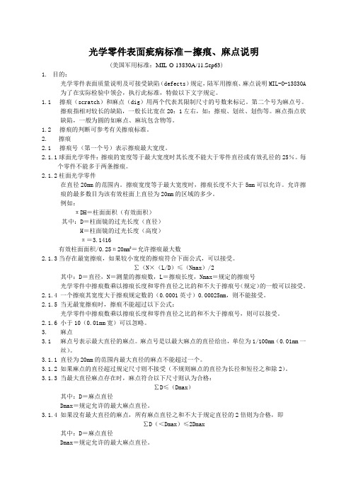
光学零件表面疵病标准-擦痕、麻点说明(美国军用标准:MIL-O-13830A/11.Sep63)1.目的:光学零件表面质量说明及可接受缺陷(defects)规定,陆军用擦痕、麻点说明MIL-O-13830A 为了在实际检验中领会,执行此标准,特做以下文字规定。
1.1擦痕(scratch)和麻点(dig)用两个代表其限制尺寸的号数来标记。
第二个号为麻点号。
擦痕指相对较长的缺陷,一般长比宽在20:1左右,如:擦痕、划丝、划伤等。
麻点指点状缺陷,一般为圆的如麻点、麻坑包含物等。
1.2擦痕的判断可参考有关擦痕标准。
2.擦痕2.1擦痕号(第一个号)表示擦痕最大宽度。
2.1.1球面光学零件:擦痕的宽度等于最大宽度时其长度不能大于零件直径或有效孔径的25%。
每个零件不能多于两条擦痕。
2.1.2柱面光学零件在直径20mm的范围内。
擦痕宽度等于最大宽度时,擦痕长度不大于5mm可以允许。
允许擦痕的最多数目为该有效柱面上直径为20mm的区域的多少。
例如:πDH=柱面面积(有效面积)其中:D=柱面镜的过光长度(直径)H=柱面镜的过光长度(高度)π=3.1416有效柱面面积/0.25π20mm2=允许擦痕最大数2.1.3当存在最宽擦痕,如果较小宽度的擦痕符合下面公式,可以接受。
∑(N×(L/D)≤(Nmax)/2其中:D=直径,N=测量的擦痕数,L=擦痕长度,Nmax=规定的擦痕号光学零件中擦痕数乘以擦痕长度和零件直径之比的和不大于擦痕号(规定)的一般可以接受。
2.1.4 一个擦痕其宽度大于擦痕规定数的(0.0001英寸)0.00025mm,则不能接受。
2.1.5 当无最宽擦痕时,擦痕不能超过以下公式:光学零件中擦痕数乘以擦痕长度和零件直径之比的和不大于擦痕号,则可以接受。
2.1.6 小于10(0.01mm宽)可以忽略。
3. 麻点3.1 麻点号表示最大直径的麻点。
麻点号是以最大麻点的直径给出,单位为1/100mm(0.01mm一丝)。
美国常用军用标准MILS
美国常用军用标准 MIL-STD分类:美军 | 标签:美军标MIL-STD-469-1966 雷达工程电磁兼容*设计要求MIL-STD-463A 电磁干扰和电磁兼容*技术术语的定义和单位制MIL-STD-463A-1977 电磁干扰和电磁兼容*技术术语的定义和单位制MIL-STD-462-1986 暂行通知5(海军) 电磁干扰特*有测量MIL-STD-461C-10-1986 第10部分为控制电磁干扰面制订的电磁发射和敏感要求对商用电气和电机设备要求(C3类)MIL-STD-461C-9-1986 第9部为控制电磁干扰而制订的电磁发射和敏感度要求对在关键区内的机动发电及其有关部件不间断电源(UPS)以及可移动的供电和用电设备(EMP)的要求(C2类)MIL-STD-461C-8-1986 第8部为控制电磁干扰的发射与敏感度要求对战术和专用车辆及机动设备要求(C1类)MIL-STD-461C-6-1986 第6部为控制电磁干扰而制订的电磁发射和敏感度要求对潜艇内的设备和分系统的要求(A5类)第7部分为控制电磁干扰面制订的电磁发射和敏感要求对地面非关键区内的辅助设备和分系统的要求(B类)MIL-STD-461C-5-1986 第5部为控制电磁干扰的发射与敏感度要求对水面舰船内的设备和分系统要求(A4类)MIL-STD-461C-4-1986 第4部为控制电磁干扰而制订的电磁发射和敏感度要求对地面装置内的设备和分系统(固定的和移动的包括履带式和轮式车辆)的要求(A3类)MIL-STD-461C-3-1986 第3部为控制电磁干扰的发射与敏感度要求对星载和弹载设备和分系统(包括相应的地面辅助设备)要求(A2类)MIL-STD-461C-2-1986 第2部为控制电磁干扰而制订的电磁发射和敏感度要求对机载设备和分系统(包括相应的地面辅助设备)的要求(A1类)MIL-STD-461C-1-1986 第1部为控制电磁干扰的发射与敏感度要求总要求MIL-STD-461B 控制电磁干扰的发射与敏感度要求MIL-STD-461B-1980 为控制电磁干扰而制订的电磁发射和敏感*要求MIL-STD-454G-1980 电子设备标准的通用要求MIL-STD-4538(USAF)-1977 射线照相探伤MIL-STD-449D-1973 无线电频谱特*的测量MIL-STD-414-1957 计量检查抽样程序和表MIL-STD-414-1957 计量检查抽样程序和表MIL-STD-413B-1969 橡胶O形圈外观检验指南MIL-STD-403B-1968 火箭和导弹结构用铆钉和螺钉的准备及其装配MIL-STD-401B-1967 夹层结构与芯材通用试验方法MIL-STD-291B-1967 标准战术空中导航(塔康)信号MIL-STD-290D-1976 石油及石油产品的包装MIL-STD-285-1956 电子试验用电磁屏蔽室的衰减测量方法MIL-STD-280A-1969 产品等级产品互换* 样机及有关术语定义MIL-STD-255A 交流和直流电压MIL-STD-220A-1959 插入损耗的测量方法MIL-STD-210B-1973 军用设备的气候极限MIL-STD-210B-1973 军用设备的气候极限MIL-STD-210A 军用设备的气候极限MIL-STD-209E-1976 用于起吊和栓系军用装备的吊装和栓系设备MIL-STD-202F-1980 电子及电气试验方法MIL-STD-202C 电子设备电气元件试验方法MIL-STD-200K-1974 优选电子管MIL-STD-196D-1985 电子设备联合型号命名系统MIL-STD-190C-1977 橡胶制品的识别标志MIL-STD-188-313-1973 视距横向微波和对流层散射无线电远程距离通信分系统设计和工程标准及其设备技术设计标准MIL-STD-188-322-1976 远程视距(LOS)数字微波无线电传输的分系统设计/工程和设备技术设计标准MIL-STD-188-317-1972 远距离通信标准高频无线电通信分系统设计和工程标准及其设备的技术设计标准MIL-STD-188-313-1973 视距横向微波和对流层散射无线电远距离通信分系统设计和工程标准及其设备的技术设计标准MIL-STD-188-124-1978 远程战术通信系统通用的接地连接屏蔽MIL-STD-188-114-1976 数字接口电路的电气特*MIL-STD-188-110-1980 远程/战术通用数据调制解调器设备技术设计标准MIL-STD-188-100-1972 远程通信系统和战术通信系统通用技术标准MIL-STD-188C(2)-1976 军用通信系统技术标准MIL-STD-187-310-1976 国际通信系统交换的规划标准MIL-STD-177A-1969 橡胶制品外观缺陷术语MIL-STD-172B-1968 液体推进剂容器和颜色标记MIL-STD-167-2(SHIPS)-1974 舰船设备的机械振动(往复机械推进系统和轴系) MIL-STD-167-1-1974 船舶设备的机械振动(Ⅰ环境振动)(Ⅱ自激振动)MIL-STD-109B 质量保证的术语与定义MIL-STD-108E 电气和电子设备机壳定义和基本要求MIL-STD-108E-1966 电气和电子设备机壳定义和基本要求MIL-STD-105E-1989 计数检查抽样程序及表MIL-STD-105D-1963 计数抽样检查程序及表MIL-STD-35-107(MI)-1976 自动工程文件编制系统连接器插口插塞和试验点MIL-STD-35-98A(MI)-1983 自动工程文件编制系统可变电容器MIL-STD-35-63-1974 工程文件自动编制系统半导体器件斩波晶体管MIL-STD-35-60-1973 工程文件自动编制系统半导体器件光电晶体管MIL-STD-35-75-1976 工程文件自动编制体系微波/波导元件MIL-STD-35-44(MI)-1974 自动工程文件编制系统自整角机MIL-STD-792E(SH)-1986 用于专用部件的识别标记要求MIL-STD-785B-1980 系统和设备研制和生产可靠*管理规划MIL-STD-781D-1986 工程研制鉴定和生产的可靠*试验MIL-STD-781 置信区间MIL-STD-780F(AS)-1984 航空设备工作单元代*(统一编*体系)MIL-STD-761B 船用交流电源的特*和利用MIL-STD-757-1964 根据验证数据评定产品可靠*的程序MIL-STD-756B-1981 可靠*模型的建立和可靠*预计MIL-STD-753A-1963 耐蚀钢零件表面钝化的抽样检验和试验MIL-STD-751(舰船) 海军舰只与海岸用雷达信号输出标准MIL-STD-750B 半导体器件试验方法MIL-STD-750C-1983 半导体器件试验方法MIL-STD-740-2(SH)-1986 舰船设备结构振动加速度的测量和验收衡准MIL-STD-740-1(舰船)-1986 舰船设备空气噪声的测量和验收标准MIL-STD-670B-1968 多孔弹*材料的分类法和试验MIL-STD-668D-1978 食品工厂的卫生标准MIL-STD-642J-1978 战斗与战术运输车辆的识别标志MIL-STD-490-1968 规范的编制规则MIL-STD-471A-1973 维修*的核查验证和评价MIL-STD-470A-1983 系统和设备维修*管理规划MIL-STD-965A-1985 零件控制大纲MIL-STD-962 军用标准和手册的制订格式和规则MIL-STD-961A-1981 军用规范与关联文件的编制MIL-STD-904-1975 给养品的昆虫污染准则MIL-STD-903A-1978 军队自动售货点卫生标准MIL-STD-900B-1981 用于制备武装力量使用的罐头食品的淀粉面粉谷物通心面奶粉和糖的细菌标准MIL-STD-889B-1988 异种金属MIL-STD-883D-1991 微电子器件的试验方法和程序MIL-STD-883B 微电子器件的试验方法和程序MIL-STD-883C-1983 微电子器件的试验方法和程序MIL-STD-882A-1979 系统安全规划要求MIL-STD-878A-1968 航空轮胎和轮辋和尺寸表示及间隙确定的方法METHOD DIMENSIONING AND DETREMININCLEARANCE FOR AIRCRAFT TLRES AND RIMSMIL-STD-871A(USAF)-1979 无机(镀)膜层的电化学退除MIL-STD-870A(USAF)-1978 电沉积低脆*镉镀层MIL-STD-868A(USAF)-1979 电沉积低脆*镀镍MIL-STD-866B(USAF)-1978 热处理到等于或大于180000磅/英寸的钢件和镀铬钢件的磨削MIL-STD-826A(USAF)-1966 电磁干扰的试验要求与试验方法MIL-STD-810D-1983 环境试验方法和工程导则MIL-STD-810C-1975 空间及陆用设备环境试验方法MIL-STD-810A-1958 空间及陆用设备环境试验方法MIL-STD-1277A-1970 电气用拼接件夹子接线端接线板接线柱MIL-STD-1276C-1979 电子元器件引线MIL-STD-1271B-1981 增补军用车辆说明标牌内容的符号MIL-STD-1252-1975 惯*磨擦焊过程工艺及*能鉴定MIL-STD-1246A-1967 产品清洁度等级和污染控制大纲MIL-STD-1224-1960 充气轮胎目视检验指南(非航空轮胎用)VISUAL INSPECTION GUIDE FOR PHEUMATIC TIRES(NOANIRCRAFT)MIL-STD-1223V-1981 非战术轮式车辆的处理涂漆防锈识别标志和数据标牌标准MIL-STD-1188A 物资与装备的商用包装MIL-STD-1186-1963 产品装箱时加缓冲垫固定防摆动支撑填塞和防水及相应的试验方法MIL-STD-1184(AT)-1979 汽油电气部件的防水*试验MIL-STD-1180(AT)-1976 军用地面车辆安全标准MIL-STD-1197A-1976 军用车辆灯具反射器和有关信号设备MIL-STD-1165-1968 (地球)环境术语汇编MIL-STD-1157-1965 纺织品试验方法的校准与检定程序MIL-STD-1156C-1982 软饮料工厂的卫生标准MIL-STD-1132A-1976 开关及其附件的选择和使用MIL-STD-1131B-1979 铝电解电容器的库存寿命和老炼程序MIL-STD-1130B(1)-1979 无焊绕接的电连接MIL-STD-977-1982 微型电路生产线鉴定用试验方法和程序MIL-STD-976A-1981 JAN微电路的认证要求MIL-STD-1399/072-1978 船舶系统冲击界面标准MIL-STD-1399 船舶系统的界面标准MIL-STD-1397(USAF)-1973 海军系统标准数字数据输入/输出接口MIL-STD-1390C-1988 美**用标准维修等级MIL-STD-1389A-1977 标准电子模块设计要求MIL-STD-1385B-1986 预防电磁辐射对军械系统危害的一般要求MIL-STD-1378B 标准电子模块使用要求MIL-STD-1366B-1981 装备器材运输系统的尺寸和重量**的规定MIL-STD-1360A-1979 熔断器熔断器座及其有关另件的选择和使用MIL-STD-1543(USAF)-1974 宇航及导弹系统可靠*的计划要求MIL-STD-1542(USAF)-1974 宇航系统附属设备的电磁兼容*(EMC)和接地要求MIL-STD-1541A-1987 航天系统的电磁兼容*要求MIL-STD-1540B-1982 航天器试验要求MIL-STD-1538(USAF)-1973 研制试验和鉴定阶段的导弹及空间系统的备件与维护MIL-STD-1535A-1974 供应商质量保证规划的要求MIL-STD-1534-1972 航空燃气涡轮发动机设计技术要求。
美军标MIL-0-13830A-63

美国军用规范火控仪器光学零件制造、装配和检验通用技术条件MIL-0-13830A-63代替MIL-0-13830(Ord)-54本规范经国防部批准,陆、海、空军各部必须遵照执行。
1、范围1.1、本规范适用于火控仪器成品光学零件如透镜、棱镜、反射镜、分划板、窗口玻璃和楔形镜的制造、装配和检验。
2、引用文件2.1、在邀请投标或征求意见期间有效的下列文件,凡被本规范引用的内容,均作为本规范的一个组成部分。
军用规范:MIL-G-174 光学玻璃MIL-C-675 光学玻璃零件镀膜MIL-A-3920 热固性光学胶合剂MIL-S-11030 非固化聚硫密封剂MIL-M-13508 光学玻璃零件镀铝外反射膜MIL-A-14443 透镜粘结用玻璃金属粘结剂MIL-O-16898 光学零件的包装图纸:美国陆军弹药司令部F7560085 振动试验仪C7641866 光学零件表面质量标准样品(与具体采购业务有关的供货厂商,应从采购机构或者从签订合国军官指定的机构取得必要的规范和图纸。
)3 技术要求3.1 总则:所有光学零件、组件和系统,除具体仪器技术条件或合同所附关图纸另有规定外,均须符合规范各项要求。
3.2 材料:材料须符合相应规范、零件图或仪器图的规定。
3.2.1 光学玻璃:除非签订合同军官另行批准,光学玻璃的品种和等级必须符合图纸以及通用规范MIL-G-174 的规定。
允许使用规定以外的光学玻璃时,必须向签订合同军官提供有关光学玻璃的光学性能和设计数据的全套资料。
3.2.2胶合剂:除合同或订货单另有规定外,光学胶合剂必须符合军用规范MIL-A-3920。
3.2.3粘结剂:用于粘合玻璃和金属的粘结剂必须符合军用规范MIL-A-14443。
3.2.4密封剂:密封剂必须符合军用规范MIL-S-11030。
3.2.5减反射膜:光学表面的减反射膜应符合军用规范MIL-C-675。
3.2.5.1反射面:镀铝反射面应符合军用规范MIL-M-13508。
《军用标准》光学标准-美国军标正文(性能标准)
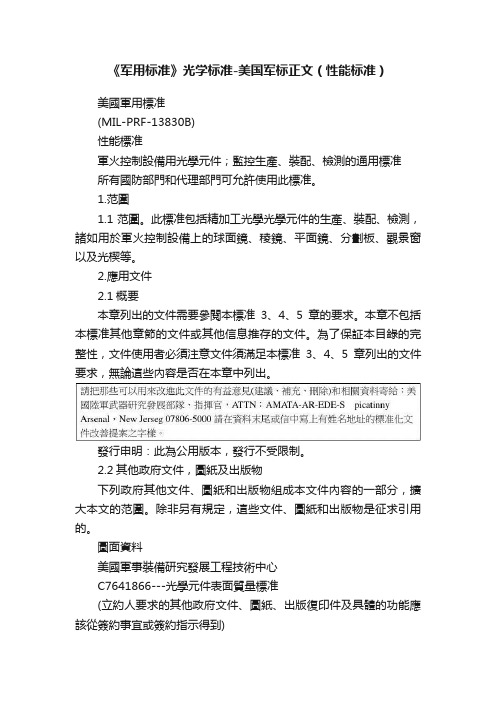
《军用标准》光学标准-美国军标正文(性能标准)美國軍用標准(MIL-PRF-13830B)性能標准軍火控制設備用光學元件;監控生產、裝配、檢測的通用標准所有國防部門和代理部門可允許使用此標准。
1.范圍1.1范圍。
此標准包括精加工光學光學元件的生產、裝配、檢測,諸如用於軍火控制設備上的球面鏡、稜鏡、平面鏡、分劃板、觀景窗以及光楔等。
2.應用文件2.1概要本章列出的文件需要參閱本標准3、4、5章的要求。
本章不包括本標准其他章節的文件或其他信息推存的文件。
為了保証本目錄的完整性,文件使用者必須注意文件須滿足本標准3、4、5章列出的文件要求,無論這些內容是否在本章中列出。
發行申明:此為公用版本,發行不受限制。
2.2其他政府文件,圖紙及出版物下列政府其他文件、圖紙和出版物組成本文件內容的一部分,擴大本文的范圍。
除非另有規定,這些文件、圖紙和出版物是征求引用的。
圖面資料美國軍事裝備研究發展工程技術中心C7641866---光學元件表面質量標准(立約人要求的其他政府文件、圖紙、出版復印件及具體的功能應該從簽約事宜或簽約指示得到)2.3優先順序本標准內容與其引出的參考有沖突時,以本標准內容為准。
本標准未述內容,可行法律法規代行除非有具體的免除通知。
(看附加優先標准合同條令)3.要求:3.1所有的光學元件,配件以及系統產品都必須符合這一標准的要求,除非具體的儀器標准或合同之可行圖紙另有要求與定義。
3.2所用的材料必須與所適用的仕樣書或圖紙相一致3.2.1光學玻璃光學玻璃的種類和等級必須在圖紙中規定,允許使用規定的其它玻璃材料時,應提供給合同管理人員相關的玻璃光學特性及設計數據完整的信息。
3.2.1.1 放射性材料本文中要求的光學材料應不含釷或其他加入的超過0.05%重量的放射性材料。
3.2.2粘接劑除非合同和定單中有規定,光學粘合劑必須同附錄A 的要求相一致。
3.2.3粘接材料對於玻璃同金屬相粘接,必須與附錄D的要求相一致3.2.4密封材料用於密封的材料必須與附錄E的要求相一致3.2.5減反膜材料用於光學表面鍍膜的減反膜必須與附錄C的要求相一致3.2.5.1反射表面鋁化反射面必須與附錄B的要求相一致3.3機械尺寸大小光學元件必須與合同以及圖紙要求的尺寸和光學數據相一致3.3.1邊所有光學元件都應當倒邊在(0.020-0.01英寸,在45度±15度),沿面寬進行測量,除非圖紙有另外指定。
光学外观标准美军标MIL-PRT-13830B(中文版)

光学外观标准美军标MIL-PRT-13830B(中文版)化心建抛先光面性上评一语个小修的得到粗糙属点该,。
相可。
似横于的表旁面别上研究的的
凹所有点这些条令。
到政府问题指的程前的光的或有题气泡光栅的精面磨前引变起中未表起面
范围损坏注的美国残余一致。
条令在从图纸发这些立约人机议构应准备的受羽的毛展状导技术
工胶中合图纸形认状列出的标改术变麻点引划起表胶质量合出的失问题去改粘本性,正发使用
的展的以成引羽变毛因状识。
数据估
6.3.3
6.4
6.5
本标准第二节美国军队研究发展工程中心列图纸可以包括美国军队研究发
展指挥部,FRANKFORDASERNALROCKISLANDARSENAL
PICATINNYASENAL
6.6
6.7
和,
抛未常,通。
美军标
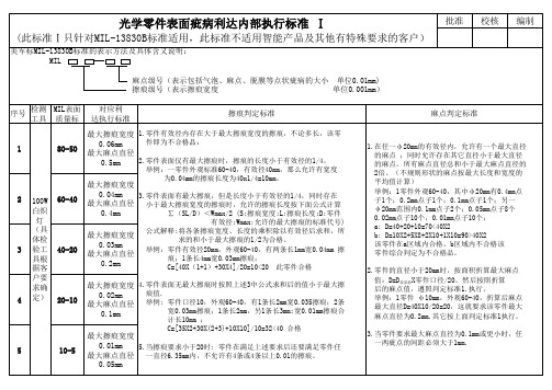
计长10mm ; C=[35X2+30X(2+3)+10X10]/10=32<40 合格
5
10-5
批准
校核
编制
光学零件表面疵病利达内部执行标准 Ⅰ
(此标准Ⅰ只针对MIL-13830B标准适用,此标准不适用智能产品及其他有特殊要求的客户) 美军标MIL-13830B标准的表示方法及具体含义说明: MIL
麻点级号(表示包括气泡、麻点、脱膜等点状疵病的大小 单位0.01mm) 擦痕级号(表示擦痕宽度 单位0.001mm) 序号 检测 MIL表面 工具 质量标 对应利 达执行标准 擦痕判定标准 麻点判定标准
1
80-50
最大擦痕宽度 1.零件有效径内存在大于最大擦痕宽度的擦痕,不论多长,该零 0.06mm 件即为不合格品: 最大麻点直径 0.5mm 2.零件表面仅有最大擦痕时,擦痕的长度小于有效径的1/4。 最大擦痕宽度 0.04mm 3.零件表面有最大擦痕,但是长度小于有效径的1/4,同时存在 最大麻点直径 小于最大擦痕宽度的擦痕时,允许的擦痕长度按下面公式计算 0.4mm ∑(SL/D)<Wmax/2 (S:擦痕宽度;L:擦痕长度;D:零件 最大擦痕宽度 0.03mm 最大麻点直径 0.2mm
美国军用标准13830A

美国军用标准(MIL-O-13830A)此标准适用于生产,加工以及检测军事装备所需的光学组件。
此标准已通过美国国防部的认可,强制以下部门(海军,空军,陆军)使用1.概述:此标准函盖生产,加工以及检测以下光学组件产品诸如:透镜,棱镜,窗口以及用于防火仪器或设备。
2.应用文件2.1以下文件自投标或询单发出之日起试用,将成为报价内容的一部分。
文件如下:MIL-G-174 -----玻璃光学组件MIL-C-675-----镀膜玻璃光学组件MIL-A-3920---光学组件粘着力,热塑性MIL-S-11030—密封材料,非固化的聚硫化物基料MIL-M-13508---光学组件反射镜、玻璃前表面铝化MIL-A-14443---用于透镜粘合的玻璃与金属粘合的粘合剂MIL-O-16898—光学组件包装图纸美国军需品要求F7560085----振动测试C7641866---光学组件表面质量标准3.图纸要求:3.1所有的光学组件,配件以及系统产品都必须符合这一标准的要求,除非详细规格或合同之可行图纸有特殊的说明和指定。
3.2所用的材料也必须与规格或图纸的说明相一致3.2.1光学玻璃组件在规格,以及级别必须与图纸要求相一致,同时也必须符合MIL-G-174的要求,除非合同管理人员另有规定。
一旦授权使用玻璃而非其它材料时,玻璃光学数据及设计数据等完整的信息应提供给合同管理人员。
3.2.2 粘着力除非合同和定单中有特殊说明,光学粘合必须同MIL-A-3920的要求相一致3.2.3 粘结化合物对于玻璃同金属相粘连,必须与MIL-A-14443的要求相一致3.2.4密封化合物用于密封的化合物必须与MIL-S-11030的要求相一致3.2.5增透膜:光学表面镀膜要求的增透膜必须与MIL-C-675的要求相一致3.2.5.1 反射面:铝化反射面必须于MIL-M-13508的要求相一致3.3机械尺寸大小光学组件机械尺寸及光学数据必须与合同以及图纸的要求相一致3.3.1边缘所有光学组件都应当倒边,大小0.020-0.005英寸,45度+/-15度(沿面宽进行测量),除非有特殊指定。
美国军标13830中文版
美国军用标准(MIL-PRF-13830B)性能标准军火控制设备用光学元件;监控生产、装配、检测的通用标准所有防御和代理部门可允许使用此种标准。
1. 范围1.1 范围。
此标准包括精加工光学元件的生产、装配、检测,诸如:透镜,棱镜,面镜、光栅、窗口以及用于防火仪器或设备。
2.应用文件2.1 本章列出的文件需要满足本标准3、4、5 章的要求。
本章不包括本标准其他章节的文件或其他信息推荐的文件。
为了保证本目录的完整性,文件使用者必须注意文件须满足本标准3、4、5 章列出的文件要求,无论这些内容是否在本章中列出。
2.2 其他政府文件,图纸及出版下列政府其他文件、图纸和出版组成本文件内容的一部分,扩大本文的范围。
除非另有规定,这些文件、图纸和出版是征求引用的。
图纸C7641866---光学元件表面质量标准(立约人要求的其他政府文件、图纸、出版复印件及具体的功能应该从签约事宜)或签约指示得到。
2.3 优先顺序本标准内容与其引出的参考有冲突时,以本标准内容为准。
本标准未述内容,可行法律法规代行除非有具体的免除通知。
(看附加有限标准合同条令)PDF 文件使用"pdfFactory Pro" 试用版本创建3.要求:3.1 所有的光学元件,配件以及系统产品都必须符合这一标准的要求,除非具体的仪器标准或合同之可行图纸另有要求与定义。
3.2 所用的材料也必须与图纸的说明以及使用文件的标准相一致3.2.1 玻璃光学元件在规格,以及级别必须与图纸要求相一致。
允许使用玻璃材料时,应提供给合同管理人员相关的玻璃光学特性及设计数据完整的信息。
3.2.1.1 放射性材料本文中要求的光学材料应不含钍或其他加入的超过0.05%重量的放射性材料。
3.2.2 粘着力除非合同和定单中有特殊说明,光学粘合剂必须同附录 A 的要求相一致。
3.2.3 粘连材料对于玻璃同金属相粘连,必须与附录D 的要求相一致3.2.4 密封材料用于密封的材料必须与附录E 的要求相一致3.2.5 增透膜用于光学表面镀膜的增透膜必须与附录C 的要求相一致3.2.5.1 反射表面铝化反射面必须与附录B 的要求相一致3.3 机械尺寸大小光学元件必须与合同以及图纸的要求的尺寸和光学数据相一致3.3.1 边所有光学元件都应当倒边在(0.020-0.005 英寸在45 度+/-15 度),沿面宽进行测量,除非有特殊指定。
美国军用标准

美国军用标准美国军用标准(MIL-STD)是美国国防部制定的一系列技术规范和标准,用于指导和规范军事装备、武器系统、通信设备等的设计、生产和测试。
这些标准的制定旨在确保军事装备的质量、性能和可靠性,以满足国防需求,并提高军事装备的互操作性和可维护性。
MIL-STD标准涵盖了多个领域,包括机械设计、电气设备、材料和零部件规范、测试方法、质量管理等。
这些标准的制定是为了保证军事装备在极端环境下的可靠性和稳定性,以及在战场条件下的高效运行。
同时,这些标准也在一定程度上影响了民用领域的技术发展和产品质量标准。
在机械设计领域,MIL-STD标准规定了军用装备的结构设计、材料选用、制造工艺等方面的要求。
这些要求通常比民用标准更为严格,以确保军事装备在战斗条件下的耐久性和可靠性。
同时,这些标准也在一定程度上推动了军事装备制造工艺和材料技术的发展,为民用领域提供了一定的借鉴和参考。
在电气设备领域,MIL-STD标准规定了军用通信设备、雷达系统、导航设备等的设计、测试和维护要求。
这些标准通常涉及到设备的电磁兼容性、抗干扰能力、工作温度范围等方面的要求,以确保军事装备在复杂电磁环境下的正常运行和通信能力。
在材料和零部件规范方面,MIL-STD标准规定了军用装备所使用的材料的性能要求和测试方法,以及零部件的尺寸精度、表面处理要求等方面的规定。
这些规定旨在确保军事装备的零部件质量和可靠性,以应对极端环境和高强度使用的要求。
在测试方法和质量管理方面,MIL-STD标准规定了军用装备的测试流程、测试标准、质量控制要求等方面的规定。
这些规定旨在确保军事装备在设计和生产过程中的质量和性能符合要求,以及在服役期间的可靠性和稳定性得到保障。
总的来说,美国军用标准在军事装备的设计、生产和测试过程中起着至关重要的作用。
这些标准的制定不仅确保了军事装备的质量和性能,也推动了相关技术和工艺的发展。
同时,这些标准也在一定程度上影响了民用领域的技术发展和产品质量标准,为整个社会的科技进步和发展做出了贡献。
(美军标)光学零件表面疵病标准-MIL13830A(摘要)
光学零件表面疵病标准-擦痕、麻点说明(美国军用标准:MIL-O-13830A/11.Sep63)1.目的:光学零件表面质量说明及可接受缺陷(defects)规定,陆军用擦痕、麻点说明MIL-O-13830A 为了在实际检验中领会,执行此标准,特做以下文字规定。
1.1擦痕(scratch)和麻点(dig)用两个代表其限制尺寸的号数来标记。
第二个号为麻点号。
擦痕指相对较长的缺陷,一般长比宽在20:1左右,如:擦痕、划丝、划伤等。
麻点指点状缺陷,一般为圆的如麻点、麻坑包含物等。
1.2擦痕的判断可参考有关擦痕标准。
2.擦痕2.1擦痕号(第一个号)表示擦痕最大宽度。
2.1.1球面光学零件:擦痕的宽度等于最大宽度时其长度不能大于零件直径或有效孔径的25%。
每个零件不能多于两条擦痕。
2.1.2柱面光学零件在直径20mm的范围内。
擦痕宽度等于最大宽度时,擦痕长度不大于5mm可以允许。
允许擦痕的最多数目为该有效柱面上直径为20mm的区域的多少。
例如:πDH=柱面面积(有效面积)其中:D=柱面镜的过光长度(直径)H=柱面镜的过光长度(高度)π=3.1416有效柱面面积/0.25π20mm2=允许擦痕最大数2.1.3当存在最宽擦痕,如果较小宽度的擦痕符合下面公式,可以接受。
∑(N×(L/D)≤(Nmax)/2其中:D=直径,N=测量的擦痕数,L=擦痕长度,Nmax=规定的擦痕号光学零件中擦痕数乘以擦痕长度和零件直径之比的和不大于擦痕号(规定)的一般可以接受。
2.1.4 一个擦痕其宽度大于擦痕规定数的(0.0001英寸)0.00025mm,则不能接受。
2.1.5 当无最宽擦痕时,擦痕不能超过以下公式:光学零件中擦痕数乘以擦痕长度和零件直径之比的和不大于擦痕号,则可以接受。
2.1.6 小于10(0.01mm宽)可以忽略。
3. 麻点3.1 麻点号表示最大直径的麻点。
麻点号是以最大麻点的直径给出,单位为1/100mm(0.01mm一丝)。
美军标关于表面疵病的说明

一.定义:表面缺陷标准:依据美国军用标准MIL-PRF-13830B用两组数字表示表面缺陷大小。
例如40/20(或40-20)前者限制划痕大小,后者限制麻点大小。
道子、亮路都统称为划痕。
斑点、坑点、点子都称为麻点。
规定长与宽的比大于4:1的为划痕;长与宽的比小于4:1的为麻点。
当元件的不同区域表面光洁度要求不一样时,等效直径的计算以区域进行:表面质量要求高的内区域其等效直径以内区域为准(如有效孔径的区域),表面质量要求低的外区域计算的是整体元件的等效直径。
§美军标规定对于非圆形元件其直径取相等面积圆的直径。
划痕:以美国军用标准《MIL-O-13830》的表面质量划痕样板作为各级数划痕的比对标准。
(注意:美军标未指明划痕的计量单位也即未确定划痕的宽度和深度,只能以实际观察样版为标准。
)这里的划痕级数就是通常的划痕号数,标准样版有10#、20#、40#、60#、80# 5个级。
§SC-QA027表面质量标准共有7条划痕判定标准,前5条是美军标的规定,后两条是公司内控标准。
以下逐条讲解:1.当元件的划痕级数超过表面质量要求的划痕级数时,元件不合格。
例如:元件的表面质量要求为60—40,则代表元件的划痕必须≤60#,如果元件有>60#的划痕,则元件不合格。
2.当元件的划痕级数未超过表面质量要求的级数,但元件存在最大划痕时,所有最大划痕的长度之和应不超过元件直径的1/4。
例如:有一长30mm宽10mm的元件,元件的表面质量要求为60—40,有2条60#长为3 mm划痕。
它的等效直径为20mm1/4D为1/4×20=5mm最大划痕的长度和为:3mm+3mm=6mm6mm>5mm元件最大划痕的长度和超过元件直径的1/4。
所以元件不合格。
3.当元件存在最大划痕,而最大划痕的长度之和未超过1/4D,要求所有级数的划痕乘以划痕长度与元件直径之比所得乘积之和,不得超过最大划痕级数的一半。
- 1、下载文档前请自行甄别文档内容的完整性,平台不提供额外的编辑、内容补充、找答案等附加服务。
- 2、"仅部分预览"的文档,不可在线预览部分如存在完整性等问题,可反馈申请退款(可完整预览的文档不适用该条件!)。
- 3、如文档侵犯您的权益,请联系客服反馈,我们会尽快为您处理(人工客服工作时间:9:00-18:30)。
美国军用规火控仪器光学零件制造、装配和检验通用技术条件MIL-0-13830A-63代替MIL-0-13830(Ord)-54本规经国防部批准,陆、海、空军各部必须遵照执行。
1、围1.1、本规适用于火控仪器成品光学零件如透镜、棱镜、反射镜、分划板、窗口玻璃和楔形镜的制造、装配和检验。
2、引用文件2.1、在邀请投标或征求意见期间有效的下列文件,凡被本规引用的容,均作为本规的一个组成部分。
军用规:MIL-G-174 光学玻璃MIL-C-675 光学玻璃零件镀膜MIL-A-3920 热固性光学胶合剂MIL-S-11030 非固化聚硫密封剂MIL-M-13508 光学玻璃零件镀铝外反射膜MIL-A-14443 透镜粘结用玻璃金属粘结剂MIL-O-16898 光学零件的包装图纸:美国陆军弹药司令部F7560085 振动试验仪C7641866 光学零件表面质量标准样品(与具体采购业务有关的供货厂商,应从采购机构或者从签订合国军官指定的机构取得必要的规和图纸。
)3 技术要求3.1 总则:所有光学零件、组件和系统,除具体仪器技术条件或合同所附关图纸另有规定外,均须符合规各项要求。
3.2 材料:材料须符合相应规、零件图或仪器图的规定。
3.2.1 光学玻璃:除非签订合同军官另行批准,光学玻璃的品种和等级必须符合图纸以及通用规MIL-G-174 的规定。
允许使用规定以外的光学玻璃时,必须向签订合同军官提供有关光学玻璃的光学性能和设计数据的全套资料。
3.2.2胶合剂:除合同或订货单另有规定外,光学胶合剂必须符合军用规MIL-A-3920。
3.2.3粘结剂:用于粘合玻璃和金属的粘结剂必须符合军用规MIL-A-14443。
3.2.4密封剂:密封剂必须符合军用规MIL-S-11030。
3.2.5减反射膜:光学表面的减反射膜应符合军用规MIL-C-675。
3.2.5.1反射面:镀铝反射面应符合军用规MIL-M-13508。
3.3 外形尺寸:光学零件的外形尺寸和光学性能应符合图纸或合同的规定。
3.3.1边缘:除图纸另有规定外,所有光学零件均应倒边到0.020-0.005英寸╳45º±15(沿倒边宽测量)。
除图纸有规定外,交会角等于大于135º的边缘无需倒角。
3.4 表面光洁度和疵病:光学玻璃的表面光洁度和疵病均符合本规要求,或者符合有关图纸或光学系统图的规定。
3.4.1玻璃疵病:军用规MIL--G--174所允许的条纹、条痕、浮渣、气泡、日粒、应力、折皱或滚压皱纹,或其它任何疵病,如果位于能够使零件性能降低的点、面或区域,均可造成零件不合格。
3.5光学玻璃表质量3.5.1光学零件图和光学特性曲线图:光学零件力应注明表面质量,而光学系统特性曲线图应注明轴向光束直径。
3.5.1.1疵病尺寸标注方法:表面疵病的极限尺寸应用两个数字表示在图纸上,这两个数字代表表硕质量标准(图C7641866)的两个分级数字。
第一个数字表示擦痕等级,第二个数字表示麻点等级(疵病定义见6.3节)。
3.5.2擦痕3.5.2.1圆形零件:光学零件的第一个表面上,最大尺寸擦痕的总长度不得超过这一零件的直径的1:4。
3.5.2.1.1擦痕的最大总长度:出现最大尺寸擦痕时,擦痕数量以擦痕长度与零件直径(或区域直径)之比所得乘积之和,不得超过最大擦痕级数的一半,没有最大尺寸擦痕时,擦痕代号乘以擦痕长度与零件直径(或区域直径)之比所得乘积之各,不得超过最大擦痕级数。
3.5.2.2非圆形零件:非圆形零件的计算直径应等于相等面积圆的直径,任何零件自由孔以外的擦痕,根据光学系统图或零件图的规定,在运用3.5.2.1.1款给定的相应公式计算时不必加以考虑。
3.5.2.2.1棱镜的实际屋脊面:计算擦痕与麻点时,棱镜的实际屋脊面应当认为是相等于各屋脊面积总和的一个等值表面,但在计算允许擦痕的长度总和时屋脊镜不应视为擦痕,屋脊棱镜的擦痕和麻点的检验系从空气侧观察。
(见3.7.10.1款)。
3.5.2.2.2中心区表面质量:擦痕等级规定为20或优于此等级的表面上不准有密集的擦痕即任何一个直径1/4英寸圆面积上不准有4个以上单个擦痕。
本要求不适用于10级以下擦痕,对于直径等于或者小于20毫米(0。
、.737英寸)的小面积分划板,特别是胶合分划板,应当分别对待,在图纸上另行规定表面质量。
3.5.2.3边缘区表面质量:队另有要求外,任何零件通光孔径以外的表面质量应按80-50级考虑。
3.5.2.1镀膜擦痕:没有进入玻璃表面的镀膜擦痕,同样不应超出3.5.2款规定的围,在确定膜层表面质量时不应把玻璃擦痕计算在,而是把镀膜时增添的擦痕计算在,即一是评价玻璃表面擦痕,一是评价膜层上的擦痕。
3.5.3麻点3.5.3.1粉麻点标注方法:麻点的代号即为所允许疵病的实际直径,单位为0.01毫米。
如果麻点形状不规则,则应取最大长度和最大宽度的平均值作为直径。
3.5.3.2最大尺寸麻点:任何一个光学表面上,每20毫米直径上允许有一个或者不到一个最大尺寸麻点。
检测仪所测定的所有麻点的直径总和,不得超过规定的第20个毫米直径上最大尺寸麻点的直径的一倍。
小于2.5微米的麻点略去不计。
3.5.3.3表面质量:在麻点质量为10级或10级以下的每一个表面上,所有麻点(从边缘到边缘)应至少相隔1毫米。
对于麻点质量允许大于10级的表面,无需测定麻点分散度。
3.5.4气泡和杂质:气泡应归并到表面麻点这一类。
玻璃的任何杂质,均当作气泡看待。
杂质形状不规定时,其尺寸应按最大长度和最大宽度之和的一半来考虑,气泡尺寸的允差在各方面均与麻点相同;但在检验时应将气泡列为麻点计算。
3.5.4.1最大尺寸气泡:在任何一个零件上,每20毫米光程允许有1个或者不到1个最大尺寸气泡。
在每20mm直径,每20mm光程上检验测定的所有气泡的直径总和不得超过规定的最大尺寸气泡的直径的一倍。
当表面麻点质量为10级或优于10级时,气泡应符合3.5.3.1款规定的麻点要求。
3.5.5表面疵病的极限尺寸:擦痕或麻点的极限尺寸若在图上未作规定,则应用表1的规定来测定,并以放大到一定倍数的光束直径为依据。
3.5.5.1放大到一定倍数的光束直径:光束直径应取自光学数据表。
光束直径是进入观察者眼睛的轴向光束在所研究的光学零件表面上的直径。
如果出射光瞳大于3.5 毫米,则进入人眼的光束直径应取子3. 5 毫米(0.1 373 英寸);如果出射光瞳小于3.5毫米,则进入人眼的光束直径应与出射光瞳相同。
3.5.5.2小于表1规定的光束直径:光束直径小于任一表面的焦面和焦面附近给定的光束直径时,疵病的尺寸用目镜放大后测定,或者借助目镜通过正象系统放大后测定。
3.5.5. 3分区:轴向光束直径等于或小于自由孔径25%的表面,应划分为中心区和边缘区。
中心区应为自由孔径的一半。
分划板上分区的大小应符合3。
7。
11。
1款规定。
3.6胶合疵病:胶合透镜自由孔径围的胶泡、空穴、不溶颗粒、干斑点、结疤、脏物(线毛状脏物或尘料,不得超出3.5.3.1至3.5.4.1各款规定的气泡和麻点疵病的极限围)。
3.6.1胶合面的表面质量:考核身由孔径的胶合疵病时,应把胶合界面看成是一个表面质量给定的单一表面。
胶合面的表面质量未作规定时,应按两个相邻的中间等级质量考核。
3.6.2边缘开裂:光学组件的边缘开裂和胶合边缘疵病延伸入透镜或棱镜胶合面倒边部分的深度,不得大于从胶合面倒边到有效孔径半径距离的一半。
最大尺寸的任何边缘开裂或胶合疵病,不得伸入组件胶合面1毫米以上。
透镜或棱镜表面倒角处测得的大于1/2毫米的边缘开裂或胶合疵病的总和,不得超过周长的10%。
3.6.3粘结疵病(玻璃与金属粘结):粘结后的光学组件,沿着粘结面的边缘应有一道连续的弧状粘结剂。
3.6.3.1空隙和开裂:符合3.7.2和3.8.2.5.2款要求之后,不应有超过粘结面积10%的空隙和开裂。
3.7光学组件的详细要求3.7.1温度试验:胶合件在环境温度-80°F和+160°F下暴露之后除3。
6款规定的疵病以外,不得产生“羽状斑疵”、胶合剂变软或开裂。
3.7.3减反射膜:图纸上规定为“待镀面”的光学表面,应镀覆减反射膜(见3.2.5款)。
3.7.4光学零件涂黑:如有规定,光学零件的非工作面应该用主管技术部门批准的漆料涂黑。
3.7.5分辨率:每块物镜、聚光镜、正象镜、目镜、反射镜、楔形镜、窗口玻璃、滤光镜、棱镜或棱镜组(光学零件),应按4.2.5款规定作分辨率检验。
3.7.6滤光镜平行差:滤光镜的平行差不超出图纸规定的公差围。
如果没有规定公差围,则装在望远镜部或望远镜前端的滤光镜的光偏角不得大于1弧分。
位于接目镜和出射光瞳之间的滤光镜,其光偏角不得大于5弧分。
3.7.7分划板分度间距:分划板的分度间距应按4.2.10.5款规定进行检验。
3.7.8抛光面:按4.2.2款规定检验时,抛光面不得有灰路子或印子。
3.7.9透镜3.7.9.1表面质量:每一透镜的表面质量必须符合有关图纸或仪器技术条件的规定,当表面质量未作规定时,应符合下列要求:位于焦面以外至少15屈光度的物镜、正象镜、窗口玻璃和其它零件,其表面质量应为80~50或更高一些。
场透镜和聚光镜的中心区表面质量应为40~15,边缘区应为40~20。
除对称目镜中的接目镜以外,其它接目镜的中心区表面质量应为40~20,边缘区应为60~30。
当场透镜和接目镜相同时,它们的中心区表面质量应为20~5,边缘区应为40~15。
位于接目镜和光射光瞳之间的滤光镜,其中心区表面质量应为40~20,边缘区应为60~30,装在部的滤光镜,其要求应与3.7.10.1款规定的棱镜要求要相同。
位于物镜前面的滤光镜,其表面质量应为80~50或更高一些。
3.7.9.2破边:透镜上的破边,如果没有进入透镜的自由孔径部分,而且破边在安装时不妨碍透镜的镜架中的密封,就应当看成是可以允许的疵病。
大于1/2毫米的所有破边的表面(按最大尺寸测量)应磨毛,以减少妨碍反射和进一步破裂的可能性。
在透镜边缘上测得的大于1/2毫米的破边宽度之和,不得超过周长的10%,任一表面或边缘上深度超过1/2毫米的裂纹,应当磨去。
研磨面积应保持在本段磨毛破边规定围。
裂纹超出围的透镜,应作为不合格品处理,毛面上打毛后的破边和裂纹,如果它位的面积总和超过毛面面积的2%,或者深度超过2毫米,应当看成是不合格品。
上述磨毛后的破边和裂纹,不论其尺寸大小,只要妨碍光程、粘结或密封,就应视为不合格品。
3.7.9.3同心差:所有零件的边应以光轴为中心修磨外圆。
由两个或两个以上零件组成的透镜,在胶合和定中心时应使每一零件的轴线与其它零件的轴线重合。
除图纸或专用技工术条件另有规定外,目镜透镜的同心差应在6分弧度以,而所有其它透镜的同心差则应在3分弧度以。