离子推进器
离子推进器原理

离子推进器原理离子推进器是一种通过加速离子来推动航天器的推进器。
它利用电场加速带电粒子(通常是氙气离子),将其推向空间中,从而产生推力。
离子推进器被广泛应用于卫星、深空探测器和其他太空任务中。
离子推进器的原理是基于电荷守恒原理,即电荷总量必须在任何时候都保持不变。
在离子推进器中,一个电子被从离子排出,然后被加速器加速,并与气体分子碰撞,产生电离反应。
这会产生新的离子和电子,并在推力道中加速,从而通过反冲原理推动宇宙飞船。
这个过程称为离子化。
离子推进器主要由以下几个部分组成:离子化室、加速器、减速器和排放口。
离子化室是一个加热而且高压的空间,内部充满了主要成分为惰性气体(例如氙气)的气体。
在这个室内,气体被电离成为带电粒子,例如氙气离子。
起先,每个离子负电荷相等,量级也相等。
加速器的作用是通过电场加速离子,在推进器的方向上形成推力。
在加速器中,离子被注入反射器并加速到极高速。
电场可以被控制,以便获得符合要求的推力。
加速离子的速度通常在每秒数百到数千米之间,正好足够驱动太空飞行器。
减速器的作用是将离子速度降低到足够接近宇宙飞船,以便在离开推进器之前进一步加速。
排放口则是将离子顺着推进器的方向排放出去,以形成推力。
排放口的大小和形状都可以控制,以改变推力的大小和方向。
离子推进器的优势是其推力节约部分燃料并能够提供恒定的速度,但其缺点是其推力相当小,从而需要更长时间才能加速太空飞船。
此外,离子推进器的设计复杂,因此制造成本较高。
尽管存在这些缺点,离子推进器仍然被广泛应用于深空探测器和其他类型的太空任务中,因为其能够提供极佳的速度、燃料效率和精确控制。
涡流离子加速器工作原理解析

涡流离子加速器工作原理解析涡流离子加速器(EDS,Electrodynamic Ion Thruster)是一种新型的电推进技术,已经在航天领域得到了广泛的应用。
它基于通过产生电场和磁场加速带电粒子的原理,能够提供高比冲和长持续推力,适用于航天器的姿态控制和运行轨道调整。
本文将深入探讨涡流离子加速器的工作原理,并分享对这一技术的观点和理解。
1. 什么是涡流离子加速器涡流离子加速器是一种离子推进器,与传统的化学推进器相比,它使用电力而不是化学反应来产生推进力。
涡流离子加速器主要由离子发生器、加速器(加电场和磁场)和推力室组成。
通过引入气体并通过电子轰击产生离子,然后通过加速器加速这些离子,并在推力室中排出,从而产生反作用力。
2. 工作原理涡流离子加速器的工作原理基于带电粒子在电场和磁场中受力的基本物理原理。
当气体进入发生器时,电子被加热并获得足够的能量,使其能够将气体分子电离成离子。
这些离子会被电场和磁场加速并聚焦,形成一个加速的离子束。
在涡流离子加速器中,电场和磁场起到了关键作用。
电场通过在离子附近产生一个电势梯度,使其受到推力。
磁场则用来限制离子束的径向扩散,确保离子能够保持稳定的轨道。
这样,离子束就能够以高速射出,并产生反作用力推动航天器。
3. 设计与优势涡流离子加速器设计的关键因素包括加速器内的电场和磁场形式、加速器电压和电流以及气体注射速率等。
通过合理设计这些参数,可以实现更高的比冲和较长的推力持续时间。
涡流离子加速器相比传统的化学推进器具有多个优势。
它的燃料效率更高,能够提供更高的比冲,因为化学推进器需要带上足够多的燃料和氧化剂来产生足够的推力。
涡流离子加速器具有较长的推力持续时间,能够在航天器运行期间持续提供推力,从而使得航天器的航程更加灵活。
涡流离子加速器还具有较小的推力受阻力,可以提高航天器的加速度和速度。
4. 观点和理解涡流离子加速器作为一种新兴的电推进技术,展现出了良好的应用前景。
离子推进器的制作方法

离子推进器的制作方法离子推进器是一种利用离子加速来产生推力的推进系统。
它在航天器和卫星中被广泛应用,能够提供高效的推力和较长的工作寿命。
下面将介绍离子推进器的制作方法。
制作离子推进器的第一步是准备所需材料和设备。
主要材料包括气体供应系统、离子发生器、加速器和排气系统。
其中,气体供应系统用于提供工作气体,离子发生器用于产生离子,加速器用于加速离子,排气系统用于排出加速后的离子。
接下来,制作离子推进器的第二步是组装离子发生器。
首先,将离子发生器的阳极和阴极连接到直流电源上,以产生电场。
然后,在阳极和阴极之间放置一个几何形状复杂的网格,用于产生离子。
离子发生器中的工作气体会通过网格,通过电场的作用被电离成离子。
第三步是加速离子。
离子发生器产生的离子会进入加速器,在加速器中受到静电力的作用而加速。
加速器通常采用静电场或磁场来加速离子,使其达到足够的速度。
第四步是排放离子。
加速后的离子会通过排气系统排出,形成推力。
排气系统通常包括一个喷嘴,用于产生高速离子流,并产生反作用力,从而推动航天器或卫星。
在离子推进器的制作过程中,还需要注意一些关键问题。
首先,选择合适的工作气体是十分重要的。
常用的工作气体包括氙气和氩气等。
其次,离子发生器的设计和制作需要考虑电场强度、网格形状和材料等因素,以确保离子的产生和稳定性。
另外,加速器的设计也需要充分考虑离子加速的效率和效果。
总结起来,离子推进器的制作方法包括准备材料和设备、组装离子发生器、加速离子和排放离子。
制作离子推进器需要注意工作气体的选择、离子发生器和加速器的设计等关键问题。
离子推进器的制作需要精密的工艺和技术,但它的高效推力和长寿命使其在太空探索中发挥着重要作用。
高中物理离子推进器的原理教案

高中物理离子推进器的原理教案一、引言离子推进器是一种利用离子推动力推动航天器的新型推进器。
它的原理基于电磁学和动量守恒定律,并且在航天技术中有着广泛的应用。
本教案旨在通过介绍离子推进器的原理和工作原理,使学生能够理解和应用相关的物理知识。
二、离子推进器的原理离子推进器利用电场加速离子并排出反冲气流从而产生推力。
其工作原理可以概括为以下几个步骤:1. 离子产生:离子推进器通常使用一种叫做离子源的装置来产生离子。
离子源一般由一个或多个金属阴极和一个阳极组成。
当金属阴极上加上高电压时,它会释放出电子,这些电子经过加速后会与离子源中的粒子碰撞,将其中的原子击出。
这些被击出的原子就是离子。
2. 离子加速:离子推进器会在离子产生后加上电场,以加速离子。
这个电场通常由电极产生。
当离子进入电场区域时,它们会受到电场力的作用而加速。
这样,离子的动能就得到增加。
3. 离子排出:加速后的离子会经过离子推进器的出口被排出。
排出离子的位置、速度和方向可以通过控制电场来调节。
4. 动量守恒:根据牛顿第三定律,排出离子的反作用力会产生一个推力,从而推动航天器向前运动。
三、实验演示和讲解为了帮助学生更好地理解离子推进器的原理,我们可以进行一些实验演示和讲解。
1. 实验一:离子产生准备一个金属阴极和一个阳极,并通过电源将金属阴极加上高电压。
然后,用一个检测器检测离子的产生情况,并通过实际观察,让学生了解离子是如何形成的。
2. 实验二:离子加速使用一个模型离子推进器,同时连接电源和电极。
通过调节电场的强度,演示离子在加速后的运动情况。
让学生观察和思考离子加速过程中的能量转换和动力学原理。
3. 实验三:动量守恒使用一个模型航天器,并将其固定在一个底座上。
连接一个离子推进器,并给它提供电源。
通过观察航天器的运动情况,让学生理解排出离子产生的反作用力如何推动航天器前进,并引出动量守恒的概念。
四、课堂练习和讨论为了检验学生对离子推进器原理的理解程度,可以进行一些课堂练习和讨论。
离子推进器用什么做的原理

离子推进器用什么做的原理
离子推进器的原理基于离子电动力学和牛顿第三定律。
离子推进器由离子发生器、加速器和排气口组成。
首先,在离子发生器中,通过加热或电离原子气体,将原子气体转化为带正电荷的离子。
然后,这些离子被加速器中的电场加速,使其获得较高的速度。
最后,加速的离子通过排气口射出推进器,产生反作用力推动推进器或航天器。
离子推进器的工作原理涉及到两个基本物理原理:离子电动力学和牛顿第三定律。
1. 离子电动力学:离子带电,当离子通过电场时,会受到电场力的作用,从而加速。
在加速器中,通过施加适当的电场,离子被加速到很高的速度。
根据离子电动力学,加速的离子速度与电场强度和离子电荷质量比成正比。
2. 牛顿第三定律:根据牛顿第三定律,对于每个作用力都存在一个大小相等但方向相反的反作用力。
在离子推进器中,被加速的带正电离子被排出推进器,产生一个方向相反的带有反作用力的离子束。
根据牛顿第三定律,这个反作用力将推动推进器或航天器向前运动。
因此,离子推进器利用离子电动力学加速带正电荷的离子,并利用牛顿第三定律产生的反作用力推动推进器或航天器。
这种推进器具有高速度和高燃料效率的优
点,但通常只用于长期航天任务,因为它们的推力相对较小。
离子推进器上限速度
离子推进器上限速度英文回答:The maximum speed of an ion thruster is determined by several factors, including the design and efficiency of the thruster, the available power source, and the specific propellant being used. In general, ion thrusters can achieve speeds of up to 50,000 meters per second (m/s) or more.The speed of an ion thruster is mainly limited by the exhaust velocity of the propellant ions. The exhaust velocity is determined by the energy imparted to the ions by the thruster's electric field. The higher the exhaust velocity, the faster the thruster can accelerate the ions and the higher the maximum speed it can achieve.One example of a high-speed ion thruster is the Hall effect thruster. This type of thruster uses a magneticfield to confine the plasma and increase the exhaustvelocity of the ions. Hall effect thrusters can achieve speeds of up to 30,000 m/s or more, making them suitablefor long-duration space missions.Another example is the gridded ion thruster, which uses a series of charged grids to accelerate and expel ions. Gridded ion thrusters can achieve speeds of up to 50,000m/s or more, but they are typically less efficient than Hall effect thrusters.It's important to note that while ion thrusters can achieve high speeds, they do so at a relatively low thrust. This means that it takes a longer time for an ion thruster to reach its maximum speed compared to traditional chemical rockets. However, ion thrusters are highly efficient and can operate for extended periods of time, making them ideal for long-duration space missions where speed is not the primary concern.中文回答:离子推进器的最高速度由几个因素决定,包括推进器的设计和效率、可用的功率源以及使用的特定推进剂。
离子推进器的未来应用趋势

离子推进器的未来应用趋势
离子推进器是一种利用电离气体产生推力的推进系统,具有高推力效率和高速度特点。
未来离子推进器有以下应用趋势:
1. 深空探测器和航天器:离子推进器适用于长时间、高速度的深空探测任务,例如对太阳系外行星的探测。
离子推进器可提供持续的低推力,加速航天器达到较高速度,减少飞行时间。
2. 提高小型卫星的能力:离子推进器相对于常规化学推进器更轻、更高效,适合用于小型卫星的姿态控制和轨道调整。
近年来,越来越多的商业小卫星公司开始采用离子推进器技术。
3. 陨石拦截和航天器偏转:离子推进器可以用于未来的陨石拦截任务,将陨石从其轨道上偏离。
此外,离子推进器还可以用于卫星或航天器的姿态调整,防止碰撞或与其他物体相撞。
4. 太空清理:离子推进器可以用于清理太空垃圾,通过提供推力将无用的卫星、碎片或其他垃圾从轨道上移除。
5. 太空旅行:离子推进器可以用于未来的太空旅行任务,将航天器加速到足够高的速度,以实现可行的太空旅行。
离子推进器的高速度和燃料效率将大大缩短飞行时间。
总的来说,未来离子推进器的应用将更加广泛和多样化,包括航天器、卫星、太空探测器、陨石拦截、太空清理和太空旅行等领域。
离子推进器原理

离子推进器原理离子推进器是一种利用离子动力学原理进行推进的航天推进系统。
它通过加速离子并将其排出以产生推力,从而推动航天器前进。
离子推进器的原理基于禄萨兰-塔纳效应,即利用电场和磁场对离子进行加速,产生推力。
离子推进器的工作原理相对于传统的化学推进器有着独特的优势,包括高速、高效、长寿命等特点,因此在航天领域有着广泛的应用前景。
离子推进器的工作原理主要包括离子产生、加速和排出三个步骤。
首先,离子产生是通过离子发生器将气体或液体转化为离子,通常采用电离或者电子轰击的方式将原子或分子中的一个或多个电子移除,从而形成带电的离子。
其次,加速阶段是通过电场和磁场对产生的离子进行加速,使其获得高速。
最后,排出阶段是将加速后的离子排出推进器,产生推力。
离子推进器的原理基于牛顿第三定律,即每个动作都有一个相等的反作用力。
当离子被排出时,它们会产生一个反向的推力,从而推动航天器向前。
由于离子的质量较小,因此相同的推力可以获得更高的速度,这也是离子推进器相对于化学推进器的优势之一。
离子推进器的工作原理还涉及到电场和磁场的作用。
电场可以加速带电粒子,而磁场可以对带电粒子进行偏转和控制。
通过合理设计和控制电场和磁场的方向和强度,可以实现对离子的高效加速和排出,从而获得理想的推进效果。
在实际应用中,离子推进器的原理需要结合工程技术和材料科学,以实现高效稳定的推进效果。
例如,需要设计高效的离子发生器、精密的加速器和排出系统,以及耐高温、耐腐蚀的材料。
同时,还需要考虑能源供应、热控制、推进器布局等多个方面的因素,以实现整个推进系统的可靠运行。
总的来说,离子推进器的原理基于离子动力学和电磁学原理,通过加速离子并将其排出以产生推力,从而推动航天器前进。
离子推进器相对于传统的化学推进器具有高速、高效、长寿命等优势,因此在航天领域有着广泛的应用前景。
随着科学技术的不断发展,离子推进器的原理和技术也将不断完善,为人类探索宇宙提供更加强大的动力支持。
离子推进器结构及应用
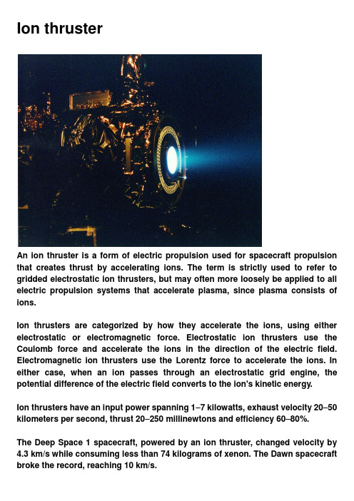
Ion thrusterAn ion thruster is a form of electric propulsion used for spacecraft propulsion that creates thrust by accelerating ions. The term is strictly used to refer to gridded electrostatic ion thrusters, but may often more loosely be applied to all electric propulsion systems that accelerate plasma, since plasma consists of ions.Ion thrusters are categorized by how they accelerate the ions, using either electrostatic or electromagnetic force. Electrostatic ion thrusters use the Coulomb force and accelerate the ions in the direction of the electric field. Electromagnetic ion thrusters use the Lorentz force to accelerate the ions. In either case, when an ion passes through an electrostatic grid engine, the potential difference of the electric field converts to the ion's kinetic energy.Ion thrusters have an input power spanning 1–7 kilowatts, exhaust velocity 20–50 kilometers per second, thrust 20–250 millinewtons and efficiency 60–80%.The Deep Space 1 spacecraft, powered by an ion thruster, changed velocity by 4.3 km/s while consuming less than 74 kilograms of xenon. The Dawn spacecraft broke the record, reaching 10 km/s.Applications include control of the orientation and position of orbiting satellites (some satellites have dozens of low-power ion thrusters) and use as a main propulsion engine for low-mass robotic space vehicles (for example Deep Space 1 and Dawn).Ion thrusters are not the most promising type of electrically powered spacecraft propulsion (although in practice they have been more successful than others).The ion drive is comparable to a car that takes two days to accelerate from zero to 60 miles per hour; a real ion engine's technical characteristics, and especially its thrust, are considerably inferior to its literary prototypes.Technical capabilities of the ion engine are limited by the space charge created by ions. This limits the thrust density (force per cross-sectional area of the engine). Ion thrusters create small thrust levels (for example the thrust of Deep Space 1's engine approximately equals the weight of one sheet of paper) compared to conventional chemical rockets, but achieve very high specific impulse, or propellant mass efficiency, by accelerating their exhaust to high speed. However, ion thrusters carry a fundamental price: the power imparted to the exhaust increases with the square of its velocity while thrust increases linearly. Chemical rockets, on the other hand, can provide high thrust, but are limited in total impulse by the small amount of energy that can be stored chemically in the propellants.Given the practical weight of suitable power sources, the accelerations given by ion thrusters are frequently less than one thousandth of standard gravity. However, since they operate as electric (or electrostatic) motors, a greater fraction of the input power is converted into kinetic exhaust power than in a chemical rocket. Chemical rockets operate as heat engines, hence Carnot's theorem bounds their possible exhaust velocity.Due to their relatively high power needs, given the specific power of power supplies and the requirement of an environment void of other ionized particles, ion thrust propulsion is currently only practical on spacecraft that have already reached space, and is unable to take vehicles from Earth to space. Spacecraft rely on conventional chemical rockets to initially reach orbit.OriginsThe first person to publish mention of the idea was Konstantin Tsiolkovsky in 1911.However, the first documented instance where the possibility of electric propulsion was considered is found in Robert H. Goddard's handwritten notebook in an entry dated September 6, 1906.The first experiments with ion thrusters were carried out by Goddard at Clark University from 1916–1917. Thetechnique was recommended for near-vacuum conditions at high altitude, but thrust was demonstrated with ionized air streams at atmospheric pressure. The idea appeared again in Hermann Oberth's "Wege zur Raumschiffahrt” (W ays to Spaceflight), published in 1923, where he explained his thoughts on the mass savings of electric propulsion, predicted its use in spacecraft propulsion and attitude control, and advocated electrostatic acceleration of charged gases.A working ion thruster was built by Harold R. Kaufman in 1959 at the NASA Glenn Research Center facilities. It was similar to the general design of a gridded electrostatic ion thruster with mercury as its fuel. Suborbital tests of the engine followed during the 1960s and in 1964 the engine was sent into a suborbital flight aboard the Space Electric Rocket Test 1 (SERT 1).It successfully operated for the planned 31 minutes before falling back to Earth. This test was followed by an orbital test, SERT-2, in 1970.An alternate form of electric propulsion, the Hall effect thruster was studied independently in the U.S. and the Soviet Union in the 1950s and 1960s. Hall effect thrusters had operated on Soviet satellites since 1972. Until the 1990s they were mainly used for satellite stabilization in North-South and in East-West directions. Some 100–200 engines completed their mission on Soviet and Russian satellites until the late 1990s.Soviet thruster design was introduced to the West in 1992 after a team of electric propulsion specialists, under the support of the Ballistic Missile Defense Organization, visited Soviet laboratories.General descriptionIon thrusters use beams of ions (electrically charged atoms or molecules) to create thrust in accordance with momentum conservation. The method of accelerating the ions varies, but all designs take advantage of the charge/mass ratio of the ions. This ratio means that relatively small potential differences can create very high exhaust velocities. This reduces the amount of reaction mass or fuel required, but increases the amount of specific power required compared to chemical rockets. Ion thrusters are therefore able to achieve extremely high specific impulses. The drawback of the low thrust is low spacecraft acceleration, because the mass of current electric power units is directly correlated with the amount of power given. This low thrust makes ion thrusters unsuited for launching spacecraft into orbit, but they are ideal for in-space propulsion applications.Various ion thrusters have been designed and they all generally fit under two categories. The thrusters are categorized as either electrostatic orelectromagnetic. The main difference is how the ions are accelerated.Electrostatic ion thrusters use the Coulomb force and are categorized as accelerating the ions in the direction of the electric field.Electromagnetic ion thrusters use the Lorentz force to accelerate the ions.Electric power supplies for ion thrusters are usually solar panels but, at sufficiently large distances from the Sun, nuclear power is used. In each case the power supply mass is essentially proportional to the peak power that can be supplied, and they both essentially give, for this application, no limit to the energy.Electric thrusters tend to produce low thrust, which results in low acceleration. Using 1 g is 9.81 m/s2; F = m a ⇒ a = F/m. An NSTAR thruster producing a thrust (force) of 92 mN will accelerate a satellite with a mass of 1,000 kg by 0.092 N / 1,000 kg = 0.000092 m/s2 (or 9.38×10⁻⁶ g).thrust = 2*η*power/(g * Isp)Wherethrust is the force in Nη is the efficiency, a dimensionless value between 0 and 1 (70% efficiency is 0.7) power is the electrical energy going into the thruster in Wg is a constant, the acceleration due to gravity 9.81 m/s2Isp is the Specific impulse in sElectrostatic ion thrustersGridded electrostatic ion thrustersSee also: electrostatic ion thrusterGridded electrostatic ion thrusters commonly utilize xenon gas. This gas has no charge and is ionized by bombarding it with energetic electrons. These electrons can be provided from a hot cathode filament and when accelerated in the electrical field of the cathode, fall to the anode. Alternatively, the electrons can be accelerated by the oscillating electric field induced by an alternating magnetic field of a coil, which results in a self-sustaining discharge and omits any cathode (radio frequency ion thruster).The positively charged ions are extracted by an extraction system consisting of 2 or 3 multi-aperture grids. After entering the grid system via the plasma sheath the ions are accelerated due to the potential difference between the first and second grid (named screen and accelerator grid) to the final ion energy of typically 1–2 keV, thereby generating the thrust.Ion thrusters emit a beam of positive charged xenon ions only. To avoid charging up the spacecraft, another cathode is placed near the engine, which emits electrons (basically the electron current is the same as the ion current) into the ion beam. This also prevents the beam of ions from returning to the spacecraftand cancelling the thrust.Gridded electrostatic ion thruster research (past/present):NASA Solar Technology Application Readiness (NSTAR) - 2.3 kW, used on two successful missionsNASA’s Evolutionary Xenon Thruster (NEXT) - 6.9 kW, flight qualification hardware builtNuclear Electric Xenon Ion System (NEXIS)High Power Electric Propulsion (HiPEP) - 25 kW, test example built and run briefly on the groundEADS Radio-Frequency Ion Thruster (RIT)Dual-Stage 4-Grid (DS4G)Hall effect thrustersSee also: Hall effect thrusterHall effect thrusters accelerate ions with the use of an electric potential maintained between a cylindrical anode and a negatively charged plasma that forms the cathode. The bulk of the propellant (typically xenon gas) is introduced near the anode, where it becomes ionized, and the ions are attracted towards the cathode; they accelerate towards and through it, picking up electrons as they leave to neutralize the beam and leave the thruster at high velocity.The anode is at one end of a cylindrical tube, and in the center is a spike that is wound to produce a radial magnetic field between it and the surrounding tube. The ions are largely unaffected by the magnetic field, since they are too massive. However, the electrons produced near the end of the spike to create the cathode are far more affected and are trapped by the magnetic field, and held in place by their attraction to the anode. Some of the electrons spiral down towards the anode, circulating around the spike in a Hall current. When they reach the anode they impact the uncharged propellant and cause it to be ionized, before finally reaching the anode and closing the circuit.Field-emission electric propulsionField-emission electric propulsion (FEEP) thrusters use a very simple system of accelerating ions to create thrust. Most designs use either caesium or indium as the propellant. The design comprises a small propellant reservoir that stores the liquid metal, a narrow tube or a system of parallel plates that the liquid flows through, and an accelerator (a ring or an elongated aperture in a metallic plate) about a millimeter past the tube end. Caesium and indium are used due to their high atomic weights, low ionization potentials, and low melting points. Once the liquid metal reaches the end of the tube, an electric field applied between the emitter and the accelerator causes the liquid surface to deform into a series of protruding cusps ("Taylor cones"). At a sufficiently high applied voltage, positive ions are extracted from the tips of the cones.The electric field created by the emitter and the accelerator then accelerates the ions. An external source of electrons neutralizes the positively charged ion stream to prevent charging of the spacecraft.Electromagnetic thrustersPulsed inductive thrustersPulsed inductive thrusters (PIT) use pulses of thrust instead of one continuousthrust, and have the ability to run on power levels in the order of Megawatts (MW). PITs consist of a large coil encircling a cone shaped tube that emits the propellant gas. Ammonia is the gas commonly used in PIT engines. For each pulse of thrust the PIT gives, a large charge first builds up in a group of capacitors behind the coil and is then released. This creates a current that moves circularly in the direction of jθ. The current then creates a magnetic field in the outward radial direction (Br), which then creates a current in the ammonia gas that has just been released in the opposite direction of the original current. This opposite current ionizes the ammonia and these positively charged ions are accelerated away from the PIT engine due to the electric field jθ crossing with the magnetic field Br, which is due to the Lorentz Force.Magnetoplasmadynamic (MPD) / lithium Lorentz force accelerator (LiLFA)Magnetoplasmadynamic (MPD) thrusters and lithium Lorentz force accelerator (LiLFA) thrusters use roughly the same idea with the LiLFA thruster building off of the MPD thruster. Hydrogen, argon, ammonia, and nitrogen gas can be used as propellant. In a certain configuration, the ambient gas in Low Earth Orbit (LEO) can be used as a propellant. The gas first enters the main chamber where it is ionized into plasma by the electric field between the anode and the cathode. This plasma then conducts electricity between the anode and the cathode. This new current creates a magnetic field around the cathode, which crosses with the electric field, thereby accelerating the plasma due to the Lorentz force. The LiLFA thruster uses the same general idea as the MPD thruster, except for two main differences. The first difference is that the LiLFA uses lithium vapor, which has the advantage of being able to be stored as a solid. The other difference is that the cathode is replaced by multiple smaller cathode rods packed into a hollow cathode tube. The cathode in the MPD thruster is easily corroded due to constant contact with the plasma. In the LiLFA thruster the lithium vapor is injected into the hollow cathode and is not ionized to its plasma form/corrode the cathode rods until it exits the tube. The plasma is then accelerated using the same Lorentz Force.Electrodeless plasma thrustersElectrodeless plasma thrusters have two unique features: the removal of the anode and cathode electrodes and the ability to throttle the engine. The removal of the electrodes takes away the factor of erosion, which limits lifetime on other ion engines. Neutral gas is first ionized by electromagnetic waves and then transferred to another chamber where it is accelerated by an oscillating electricand magnetic field, also known as the ponderomotive force. This separation of the ionization and acceleration stage give the engine the ability to throttle the speed of propellant flow, which then changes the thrust magnitude and specific impulse values.Helicon double layer thrusterA helicon double layer thruster is a type of plasma thruster, which ejects high velocity ionized gas to provide thrust to a spacecraft. In this thruster design, gas is injected into a tubular chamber (the source tube) with one open end. Radio frequency AC power (at 13.56 MHz in the prototype design) is coupled into a specially shaped antenna wrapped around the chamber. The electromagnetic wave emitted by the antenna causes the gas to break down and form a plasma. The antenna then excites a helicon wave in the plasma, which further heats the plasma. The device has a roughly constant magnetic field in the source tube (supplied by solenoids in the prototype), but the magnetic field diverges and rapidly decreases in magnitude away from the source region, and might be thought of as a kind of magnetic nozzle. In operation, there is a sharp boundary between the high density plasma inside the source region, and the low density plasma in the exhaust, which is associated with a sharp change in electrical potential. The plasma properties change rapidly across this boundary, which is known as a current-free electric double layer. The electrical potential is much higher inside the source region than in the exhaust, and this serves both to confine most of the electrons, and to accelerate the ions away from the source region. Enough electrons escape the source region to ensure that the plasma in the exhaust is neutral overall.ComparisonsThe following table compares actual test data of some ion thrusters:The following thrusters are highly experimental and have been tested only in pulse mode.LifetimeA major limiting factor of ion thrusters is their small thrust; however, it is generated at a high propellant efficiency (mass utilisation, specific impulse). The efficiency comes from the high exhaust velocity, which in turn demands highenergy, and the performance is ultimately limited by the available spacecraft power.The low thrust requires ion thrusters to provide continuous thrust for a long time to achieve the needed change in velocity (delta-v) for a particular mission. To cause enough change in momentum, ion thrusters are designed to last for periods of weeks to years.In practice the lifetime of electrostatic ion thrusters is limited by several processes:In electrostatic gridded ion thruster design, charge-exchange ions produced by the beam ions with the neutral gas flow can be accelerated towards the negatively biased accelerator grid and cause grid erosion. End-of-life is reached when either a structural failure of the grid occurs or the holes in the accelerator grid become so large that the ion extraction is largely affected; e.g., by the occurrence of electron backstreaming. Grid erosion cannot be avoided and is the major lifetime-limiting factor. By a thorough grid design and material selection, lifetimes of 20,000 hours and far beyond are reached, which is sufficient to fulfill current space missions.A test of the NASA Solar Technology Application Readiness (NSTAR) electrostatic ion thruster resulted in 30,472 hours (roughly 3.5 years) of continuous thrust at maximum power. The test was concluded prior to any failure and examination indicated the engine was not approaching failure either.More recently, the NASA Evolutionary Xenon Thruster (NEXT) Project, conducted at NASA's Glenn Research Center in Cleveland, Ohio, operated continuously for more than 48,000 hours.The test was conducted in a high vacuum test chamber at Glenn Research Center. Over the course of the 5 1/2 + year test, the engine consumed approximately 870 kilograms of xenon propellant. The total impulse provided by the engine would require over 10,000 kilograms of conventional rocket propellant for similar application. The engine was designed by Aerojet Rocketdyne of Sacramento, California.Hall thrusters suffer from very strong erosion of the ceramic discharge chamber by impact of energetic ions: a test reported in 2010 showed erosion of around 1 mm per hundred hours of operation, though this is inconsistent with observed on-orbit lifetimes of a few thousand hours.NASA's Jet Propulsion Laboratory has created ion drives with a time of continuous operation of more than 3 years.PropellantsIonization energy represents a very large percentage of the energy needed to run ion drives. The ideal propellant for ion drives is thus a propellant molecule or atom that is easy to ionize, that has a high mass/ionization energy ratio. In addition, the propellant should not cause erosion of the thruster to any great degree to permit long life; and should not contaminate the vehicle.Many current designs use xenon gas, as it is easy to ionize, has a reasonably high atomic number, its inert nature, and low erosion. However, xenon is globally in short supply and very expensive.Older designs used mercury, but this is toxic and expensive, tended to contaminate the vehicle with the metal and was difficult to feed accurately.Other propellants, such as bismuth, show promise and are areas of research, particularly for gridless designs, such as Hall effect thrusters.VASIMR design (and other plasma-based engines) are theoretically able to use practically any material for propellant. However, in current tests the most practical propellant is argon, which is a relatively abundant and inexpensive gas.Energy efficiency(Plot of instantaneous propulsive efficiency (blue) and overall efficiency for a vehicle accelerating from rest (red) as percentages of the engine efficiency- note that peak vehicle efficiency occurs at about 1.6 times exhaust velocity.)Ion thrusters are frequently quoted with an efficiency metric. This efficiency is the kinetic energy of the exhaust jet emitted per second divided by the electrical power into the device.The actual overall system energy efficiency in use is determined by the propulsive efficiency, which depends on vehicle speed and exhaust speed. Some thrusters can vary exhaust speed in operation, but all can be designed with different exhaust speeds. At the lower end of Isps the overall efficiency drops, because the ionization takes up a larger percentage energy, and at the high end propulsive efficiency is reduced.Optimal efficiencies and exhaust velocities can thus be calculated for any given mission to give minimum overall cost.ApplicationsIon thrusters have many applications for in-space propulsion. The best applications of the thrusters make use of the long lifetime when significant thrust is not needed. Examples of this include orbit transfers, attitude adjustments, drag compensation for low Earth orbits, transporting cargo such as chemical fuels between propellant depots and ultra-fine adjustments for scientific missions. Ion thrusters can also be used for interplanetary and deep-space missions where time is not crucial. Continuous thrust over a very long time can build up a larger velocity than traditional chemical rockets.MissionsOf all the electric thrusters, ion thrusters have been the most seriously considered commercially and academically in the quest for interplanetary missions and orbit raising maneuvers. Ion thrusters are seen as the best solution for these missions, as they require very high change in velocity overall that can be built up over long periods of time.Pure demonstration vehiclesSERTIon propulsion systems were first demonstrated in space by the NASA Lewis (now Glenn Research Center) missions "Space Electric Rocket Test" (SERT) Itechnology operated as predicted in space. These were electrostatic ion thrusters using mercury and cesium as the reaction mass. The second test, SERT-II, launched on February 3, 1970, verified the operation of two mercury ion engines for thousands of running hours.Operational missionsIon thrusters are routinely used for station-keeping on commercial and military communication satellites in geosynchronous orbit, including satellites manufactured by Boeing and by Hughes Aerospace. The pioneers in this field were the Soviet Union, who used SPT thrusters on a variety of satellites starting in the early 1970s.Two geostationary satellites (ESA's Artemis in 2001–03 and the US military's AEHF-1 in 2010–12) have used the ion thruster for orbit raising after the failure of the chemical-propellant engine. Boeing have been using ion thrusters for station-keeping since 1997, and plan in 2013–14 to offer a variant on their 702 platform, which will have no chemical engine and use ion thrusters for orbit raising; this enables a significantly lower launch mass for a given satellite capability. AEHF-2 used a chemical engine to raise perigee to 10150 miles and is then proceeding to geosynchronous orbit using electric propulsion.In Earth orbitGOCEESA's Gravity Field and Steady-State Ocean Circulation Explorer was launched on March 16, 2009. It used ion propulsion throughout its twenty-month mission to combat the air-drag it experienced in its low orbit before intentionally deorbiting on November 11, 2013.In deep spaceDeep Space 1NASA developed the NSTAR ion engine for use in their interplanetary science missions beginning in the late-1990s. This xenon-propelled ion thruster was first space-tested in the highly successful space probe Deep Space 1, launched in 1998. This was the first use of electric propulsion as the interplanetaryHughes Research Labs, developed the XIPS (Xenon Ion Propulsion System) for performing station keeping on geosynchronous satellites. Hughes (EDD) manufactured the NSTAR thruster used on the spacecraft.HayabusaThe Japanese space agency's Hayabusa, which was launched in 2003 and successfully rendezvoused with the asteroid 25143 Itokawa and remained in close proximity for many months to collect samples and information, was powered by four xenon ion engines. It used xenon ions generated by microwave electron cyclotron resonance, and a carbon / carbon-composite material (which is resistant to erosion) for its acceleration grid. Although the ion engines on Hayabusa had some technical difficulties, in-flight reconfiguration allowed one of the four engines to be repaired, and allowed the mission to successfully return to Earth.Smart 1The European Space Agency's satellite SMART-1, launched in 2003, used a Snecma PPS-1350-G Hall thruster to get from GTO to lunar orbit. This satellite completed its mission on September 3, 2006, in a controlled collision on the Moon's surface, after a trajectory deviation so scientists could see the 3 meter crater the impact created on the visible side of the moon.DawnDawn was launched on September 27, 2007, to explore the asteroid Vesta and the dwarf planet Ceres. To cruise from Earth to its targets it uses three Deep Space 1 heritage xenon ion thrusters (firing only one at a time) to take it in a long outward spiral. An extended mission in which Dawn explores other asteroids after Ceres is also possible. Dawn's ion drive is capable of accelerating from 0 to 60 mph (97 km/h) in 4 days, firing continuously.Planned missionsIn addition, several missions are planned to use ion thrusters in the next few years.BepiColomboESA will launch the BepiColombo mission to Mercury in 2016. It uses ion thrusters in combination with swing-bys to get to Mercury, where a chemical rocket will be fired for orbit insertion.LISA PathfinderLISA Pathfinder is an ESA spacecraft to be launched in 2015. It will not use ion thrusters as its primary propulsion system, but will use both colloid thrusters and FEEP for very precise attitude control -— the low thrusts of these propulsion devices make it possible to move the spacecraft incremental distances very accurately. It is a test for the possible LISA mission.International Space StationAs of March 2011, a future launch of an Ad Astra VF-200 200 kW VASIMR electromagnetic thruster was being considered for placement and testing on the International Space Station.The VF-200 is a flight version of the VX-200.Since the available power from the ISS is less than 200 kW, the ISS VASIMR will include a trickle-charged battery system allowing for 15 min pulses of thrust. Testing of the engine on ISS is valuable, because ISS orbits at a relatively low altitude and experiences fairly high levels of atmospheric drag, making periodic boosts of altitude necessary. Currently, altitude reboosting by chemical rockets fulfills this requirement. If the tests of VASIMR reboosting of the ISS goes according to plan, the increase in specific impulse could mean that the cost of fuel for altitude reboosting will be one-twentieth of the current $210 million annual cost.Hydrogen is generated by the ISS as a by-product, which is currently vented into space.NASA high-power SEP system demonstration missionIn June 2011, NASA launched a request-for-proposals for a test mission (from context probably using the NEXT engine) capable of being extended to 300 kW electrical power; this was awarded to Northrop Grumman in February 2012.ProposalGeoffrey A. Landis proposed for interstellar travel future-technology project interstellar probe with supplying the energy from an external source (laser of base station) and ion thruster.。
离子推进器推力计算

离子推进器推力计算离子推进器是一种电推进技术,其推进原理是利用电磁场加速离子并将其排出喷口,产生推力。
离子推进器的推力计算是非常重要的基础工作,本文将介绍离子推进器推力计算的相关知识,具体内容如下:一、推力的定义和计算公式推力是指离子推进器向相反方向喷出离子产生的力,它的大小可以通过牛顿第二定律计算得出:F=ma,其中F表示推力,m表示喷出离子的质量,a表示加速度。
根据电磁场理论,可以得到离子的加速度公式:a=qE/m,其中q表示离子带电荷量,E表示电磁场强度,m表示离子质量。
将加速度公式代入牛顿第二定律中,可以得到离子推进器的推力公式:F=qEΔm/t,其中Δm表示单位时间内喷出离子的质量,t表示喷出离子的时间。
二、推力的影响因素离子推进器的推力与离子的质量、离子的速度、电场强度等多个因素有关。
离子质量越大,推力也就越大;离子速度越快,推力也会随之增加;电场强度越大,推力也会增加。
三、离子推进器推力计算的应用离子推进器推力计算在航天技术中有着广泛的应用。
在设计航天器时,需要确定离子推进器的推力大小,以保证航天器能够完成预定任务。
同时,离子推进器推力的大小还会影响到航天器的轨道和姿态控制等方面的设计,因此推力计算是航天器设计中非常重要的一环。
四、离子推进器推力计算的优化方法为了提高离子推进器的推力性能,需要采取一系列优化措施。
例如,可以选择适当的离子种类和工作气压,以增加离子的质量和速度;可以通过改变电场强度来控制离子的加速度,从而使推力达到最大化;还可以优化喷口结构,降低喷出离子的速度分布,提高推力效率。
综上所述,离子推进器推力计算是离子推进技术中的重要内容,它与航天器的设计和性能有着密切的关系,需要进行科学、准确的计算和优化。
离子推进器原理

离子推进器原理
离子推进器是一种利用离子的运动产生推力的推进技术。
其原理可以简单地描述为以下几个步骤:
1. 电离:首先,在离子推进器内部的离子源中,将一些中性气体(如氙气或氩气)通过电子轰击进行电离。
电子可以从一个电源中获得足够的能量以使气体中的原子失去或获得电子,从而形成带有正电荷的离子。
2. 加速:接下来,这些正电荷的离子被加速器中的强电场加速。
加速器通常由两个或多个电极构成,其中一个电极带有正电荷,而另一个电极带有负电荷。
由于电荷之间的作用力,离子受到电场的作用而被加速。
3. 出口:加速的离子进入一个称为减速网的网格中,该网格带有正电荷。
当离子通过减速网时,它们失去了一部分动能,从而减速。
同时,减速网还可以阻止不必要的中性气体进入离子推进器。
4. 推进:一旦离子通过了减速网,它们会以很高的速度喷出离子推进器。
这些高速离子产生的反作用力就是推力,它使得离子推进器所在的物体(如卫星或航天器)向相反的方向移动。
总的来说,离子推进器利用电离和加速等过程将中性气体转化为离子,并通过推力来推动物体。
相比于传统的火箭推进器,离子推进器具有更高的速度和效率,但推力较小,适用于长期飞行和精确控制的任务。
离子推进飞行机的原理

离子推进飞行机的原理
离子推进飞行机的原理是利用离子推进器产生的离子流进行推进。
离子推进器采用电离技术将气体中的分子或原子电离成离子,并施加高电压加速离子,使其获得较高的速度。
离子推进器产生的离子流射出后,产生反作用力,推动飞行器向前推进。
具体实现过程如下:
1. 离子产生:通常使用电离技术,通过电离装置将进气口提供的气体(通常为氙气或氩气)电离成离子。
电离装置一般采用电子冲击或放电等方法,将气体分子或原子中的一个或多个电子击出,使其变成带正电的离子。
2. 离子加速:通过施加电场或磁场来加速离子。
通常采用电场加速的方式,将离子带上高电压,使其获得较高的速度。
3. 离子排流:加速后的离子通过一个小孔或排气管射出,形成离子流。
离子流的射出速度较高,产生的动量反作用力将飞行器推动向前。
4. 推力控制:通过改变电极电压、电流等参数,可以调节离子流的射出速度和流量,从而控制推力大小和方向。
通常在离子推进器上设置多个发动机以实现更好的推力和姿态控制。
离子推进飞行机相比传统喷气式发动机具有较高的喷气速度和比冲,但推力较小。
因此,离子推进飞行机通常适用于长期太空飞行和微小姿态调整等任务,而不适用于大负载或大速度变化的飞行任务。
离子推进器的工作原理

离子推进器的工作原理
1 简介
离子推进器是现代航天器上常用的一种推进方式,它不同于传统
的燃烧推进器,而是利用电场加速离子使其产生推力,因此具有高效、节能、长寿命等优点。
下面我们来了解一下离子推进器的工作原理。
2 离子源和电场
离子源通常由一个阴极和一个阳极组成,利用一定的能量使目标
物质发生离子化,产生正离子或负离子。
正离子和负离子分别被集中
并加速到一定速度,形成离子束。
在离子源的周围,设置了一定的电场,包括静电场和磁场。
正离
子通过电场,负离子通过磁场,分别受到作用力,产生加速效果。
3 加速和发射
离子束发射口处设置了一定的电场,它会作用于离子束,并使其
进一步加速,产生更大的动能。
离子推进器需要在航天器上实现持续推动,因此需要采用周期的
方式进行离子源充电、加速和发射等过程。
4 特点和应用
离子推进器具有高效、轻量化、长寿命、可控性和灵活性等优点,对于探索深空环境、维持星座的稳定等方面有广泛的应用。
目前,离
子推进器已经在许多航天器上得到了应用,如欧洲空间局的SMART-1号、美国国家航空航天局的Dawn号等。
离子推进器作为一种新的推进方式,具有巨大的潜力和发展前景。
离子推进器原理

离子推进器原理离子推进器是一种利用离子的动能产生推进力的推进装置,它是一种高效、节能的航天推进技术,被广泛应用于航天器、卫星和深空探测器等领域。
离子推进器的原理基于离子加速器的工作原理,通过加速离子并将其喷出,产生反作用力实现推进。
离子推进器的工作原理主要包括离子产生、加速和喷射三个步骤。
首先,离子产生是通过离子发生器将气体原子或分子转化为离子,通常采用电离或化学反应的方式进行。
其次,加速阶段是将产生的离子加速至较高速度,这通常通过电场或磁场来实现。
最后,喷射阶段是将加速后的离子喷出,产生推进力。
在离子推进器中,离子产生的方式包括电离和化学反应两种。
电离方式是通过电离器将气体原子或分子转化为离子,然后利用电场加速和引导离子。
化学反应方式是利用化学反应产生离子,然后通过磁场或电场进行加速和喷射。
这两种方式各有优劣,可以根据具体应用场景进行选择。
离子推进器的加速阶段通常采用电场或磁场来实现。
电场加速是利用电场对离子施加电力,使其加速运动;而磁场加速则是通过磁场对离子进行作用力,实现加速。
这两种方式都能够有效地提高离子的速度,从而产生更大的推进力。
最后,离子推进器的喷射阶段是将加速后的离子喷出,产生推进力。
离子喷出的速度通常很高,因此产生的推进力也较大。
离子推进器通过不断地喷射离子,可以持续地提供推进力,从而实现航天器的推进。
总的来说,离子推进器的原理是利用离子加速器的工作原理,通过离子产生、加速和喷射三个步骤来实现推进。
离子推进器具有高效、节能的特点,是未来航天技术发展的重要方向之一。
随着科学技术的不断发展,离子推进器在航天领域的应用前景将会更加广阔。
离子推进器 霍尔电推

离子推进器霍尔电推
《离子推进器——霍尔电推》
离子推进器是一种利用电场加速和排斥离子来产生推进力的航天推进技术。
其中,霍尔电推是一种成熟的离子推进器类型,被广泛应用于航天器和卫星的推进系统中。
霍尔电推的工作原理是通过利用电场和磁场相互作用的方式来加速离子。
在霍尔电推装置中,离子被加速器加速后,进入磁场区域,在磁场的作用下,离子呈螺旋状运动,最终喷出高速离子流,产生推进力。
与传统的火箭推进器相比,霍尔电推有很多优点。
首先,霍尔电推可以提供更高的比冲,即单位推进剂质量能够产生的推力效率更高。
其次,霍尔电推器有较长的使用寿命,因为其推进剂利用率高,使用寿命较长。
此外,霍尔电推器还能够提供较为稳定的推力,因此被广泛应用于长期在轨运行的卫星和航天器上。
然而,霍尔电推器也存在一些挑战。
例如,需要大量的能源来产生所需的电场和磁场,因此需要高功率的电源系统。
此外,霍尔电推器的推力较小,适用于长期、连续推进的任务,不适用于需要快速变速或大推力的任务。
总的来说,霍尔电推是一种成熟的、高效的离子推进技术,被广泛应用于航天器和卫星的推进系统中。
随着技术的不断进步,相信离子推进技术在未来的空间探索中会发挥更加重要的作用。
离子推进器极限

离子推进器是一种空间电推进技术中的一种动力装置,利用静电场加速离子喷出来产生推力。
它的推力虽然小,但是燃料重量很轻,工质加速效率很高,也就是使用很轻的气体储备,就能获得一段持续时间很长的加速度。
因此,在太空没有空气阻力的环境中,离子推进器可以将飞船加速到气体喷射速度的上限,即约80公里每秒。
请注意,离子推进器的推力小是其致命弱点,这意味着它永远无法将一个相对静止的物体加速,因此它无法用于火箭起飞等需要将物体从静止状态加速到高速的运动。
将飞船送到太空中,还是需要依靠简单粗暴的化学燃料。
以上信息仅供参考,如需了解更多关于离子推进器的信息,可查阅航空航天类书籍或咨询航空航天专家。
离子推进器原理
离子推进器原理离子推进器是一种利用离子动能产生推进力的航天推进技术,它是一种高效、节能的推进方式,被广泛应用于航天器和卫星的姿态控制、轨道修正和深空探测等任务中。
离子推进器的工作原理主要包括离子产生、加速和排出三个关键步骤。
首先,离子推进器通过离子发生器产生离子。
离子发生器通常采用禄熙管或者电子轰击离子源的方式,将气体原子或分子转化为带电的离子。
这些离子通常是氙气、氩气或者氙气等稀有气体,它们被加速器加速后形成离子束。
其次,离子束通过电场或者磁场的作用被加速。
加速器会施加高电压或者强磁场,使得离子获得高速动能。
这种高速离子束产生的动量变化就会产生推进力,从而推动航天器前进。
最后,离子推进器将加速后的离子排出。
排出过程中,离子推进器会通过排气口将离子排出,由于离子具有相对较高的速度,所以排出的离子会产生反作用力,从而推动航天器向相反的方向运动。
总的来说,离子推进器的工作原理就是通过离子的产生、加速和排出来产生推进力,从而推动航天器前进。
相比传统的火箭推进器,离子推进器具有高推进效率、长工作寿命和低燃料消耗等优点,因此在深空探测和长期任务中有着广泛的应用前景。
离子推进器的工作原理虽然看似简单,但其中涉及到了许多复杂的物理和工程原理。
例如,离子的产生和加速需要精密的离子发生器和加速器,排出过程中需要考虑到排气口的设计和排气速度的控制等问题。
因此,离子推进器的设计和制造需要多学科的知识和技术的综合应用。
除了工程技术层面的挑战,离子推进器的应用也需要考虑到宇航器的设计和任务需求。
例如,离子推进器在长期任务中的燃料消耗问题、在轨道修正和姿态控制中的精确性要求等问题都需要考虑到。
总之,离子推进器作为一种新型的航天推进技术,具有着广阔的应用前景和挑战。
通过对离子推进器工作原理的深入理解,可以更好地推动离子推进器技术的发展和应用。
相信随着科技的不断进步,离子推进器将在未来的航天领域发挥越来越重要的作用。
离子推进器[发明专利]
![离子推进器[发明专利]](https://img.taocdn.com/s3/m/a8064c7d842458fb770bf78a6529647d26283457.png)
(19)中华人民共和国国家知识产权局(12)发明专利申请(10)申请公布号 (43)申请公布日 (21)申请号 202010639938.3(22)申请日 2020.07.06(71)申请人 安徽华东光电技术研究所有限公司地址 241000 安徽省芜湖市高新技术产业开发区峨山路01(72)发明人 沈旭东 赵艳珩 朱荣帅 (74)专利代理机构 北京润平知识产权代理有限公司 11283代理人 董杰(51)Int.Cl.F03H 1/00(2006.01)(54)发明名称离子推进器(57)摘要本发明公开了一种离子推进器,包括电离室、设置在电离室前方的主阴极、自前往后依次设置在电离室后方的屏栅和加速栅;主阴极上形成有主阴极通道,电离室上位于主阴极的一侧设有进口通道,以使得推进气体能够通过主阴极通道和进口通道注入电离室;主阴极用于发射电子到电离室与推进气体碰撞以使得推进气体被电离成正离子和电子,电离室内气体为等离子态;此时,在加速栅上加上脉冲电压,当电压为正时,电子从电离室被加速,从屏栅和加速栅的孔中发射出去;当电压为负时,正离子从电离室被加速,从屏栅和加速栅的孔中发射出去,以产生与离子运动方向相反的推力来推动航天器加速运动。
其原理可行,结构简单,有效提高了航天器的使用效率。
权利要求书1页 说明书3页 附图1页CN 111878336 A 2020.11.03C N 111878336A1.一种离子推进器,其特征在于,包括电离室(1)、设置在电离室(1)前方的主阴极(2)、自前往后依次设置在电离室(1)后方的屏栅(3)和加速栅(4);其中,主阴极(2)上形成有主阴极通道,电离室(1)上位于主阴极(2)的一侧设有进口通道,以使得推进气体(5)能够通过主阴极通道和进口通道注入电离室(1);主阴极(2)用于发射电子到电离室(1)与推进气体(5)碰撞以使得推进气体(5)被电离成正离子和电子,电离室(1)内气体为等离子态;此时,在加速栅(4)上加上脉冲电压,当电压为正时,电子从电离室(1)被加速,从屏栅(3)和加速栅(4)的孔中发射出去;当电压为负时,正离子从电离室(1)被加速,从屏栅(3)和加速栅(4)的孔中发射出去,以产生与离子运动方向相反的推力来推动航天器加速运动。
- 1、下载文档前请自行甄别文档内容的完整性,平台不提供额外的编辑、内容补充、找答案等附加服务。
- 2、"仅部分预览"的文档,不可在线预览部分如存在完整性等问题,可反馈申请退款(可完整预览的文档不适用该条件!)。
- 3、如文档侵犯您的权益,请联系客服反馈,我们会尽快为您处理(人工客服工作时间:9:00-18:30)。
离子推进器
自从1998年深空1号 (Deep Space 1)发射升空之后,太空旅行
进入了离子推进的新时代,美国国家航空太空总署 (NASA)设计远航 1号的主要目的,是为了测试新的技术。 虽然深空 1号上的离子推进器所产生的加速度,远小于我们在地球上感受到的地心引力,然而它却缓缓加速太空船,使他可以横越太阳系。推进器是利用游离的氙前进的,这些离子 受到电场的加速向后喷出产生动力,它能量是来自于大片的太阳能版,这样能让太空船慢慢加速。上图高温的蓝色离子从推进器的原型机喷出,是去年在喷射推进实验室 (JPL)所完成的成功测试。 深空 1号在1999年7月成功的飞越小行星 9969 Braille, 并在2001年9月又探视了Borrelly 彗星,获得有史以来最清晰的彗星核心影像。这艘太空船已于2001年12月除役 。
但随着登月竞争的白热化,NASA将研究重点转向建造使用化学燃料为推进剂的重型运载火箭上。直到1992年,NASA Solar Electric Power Technology Applications Readiness计划才重拾当年电推进的概念,决定研制氙离子推进引擎。1996年至1997年间,喷气推进实验室在其真空室中测试了一台由Lewis 中心设计制造的氙离子引擎原型机,引擎平稳运转了8000小时。有了这一成功经验,该技术随即被Deep Space 1计划采用。
除此之外,离子引擎还可以以持久稳定的推力连续工作数月乃至数年,如此就可以将探测器加速到很快,大大地减少到达目的地所花费的时间。如有人计算过原计划探测Wirtanen彗星的Rosetta,如果它改装了离子引擎,抵达彗星所需时间就会从9年减至2年半。不过离子引擎并不象化学推进引擎那样能在短时间内产生强大的推力,所以它并不适合作为运载火箭的发动机或其他需要很大加速度的场合,实际上不论是Deep Space 1、SMART-1还是Hayabusa,都是先由运载火箭发射升空后离子引擎才开始工作的。但稳定的小推力也有自己的优点:它能方便测控人员实时精细调整在轨卫星或探测器的状态,所以对于深空探测来说,离子引擎是很好的选择。尤其是Hayabusa这样的小天体探测器,由于目标天体形状不明,需要自动导航系统实时对航向进行微调,这也许就是Hayabusa采用离子引擎的原因之一。
特点及前景
离子引擎最大的优点当然是高效。由于离子流的喷射速度比化学推进剂快很多,离子引擎每消耗单位质量的燃料,可以产生10倍与传统推进设备的推力。所以 Deep Space 1只携带了81.5
千克的氙推进剂,就可以进行20个月的飞行,这对于化学推进剂来说简直是不可想象的。
工作原理
离子引擎运转的首要条件就是制造离子气体。这通常需要由电子枪来完成。管状阴极发出的电子束被射入经磁化的电离室,与充在室中的气体原子碰撞,令原子电离成一价正离子。如上图所示,电离室的另一端装有一对金属网,网上加有上千伏(Deep Space 1的所加电压是1280伏)的电压,可将离子加速到每秒30米的速度,并从尾部排出,形成离子束,由此产生推力。在这一点上,离子推进技术与传
如果想让离子引擎正常工作,还有个疑难问题必须解决:引擎持续喷射出正离子束,会将带有负电的电子留在其中,这就形成了引擎中强大的负电场,严重阻碍了正离子的继续排出,电子积累足够多的话,甚至会将排出的正离子再吸引回来。解决此问题的方案是在喷射离子的排气网附近再安装一支电子枪作为电中和器,持续向离子束中注入电子,既可以中和离子束,又避免了引擎过度带电。
顾名思义,离子引擎就是使用电离气体作为推进剂的飞船推进设备,与太阳帆一道,都属于电推进家族。它也是目前性能最好、最成熟的电推进系统。最早的离子引擎于1960年左右由NASA的Glenn研究中心制成,但之后一直处于试验阶段,直到1998年,探测彗星的Deep Space 1计划才首次将离子引擎作为主力推进系统应用在深空飞行中。
美国华盛顿大学地球物理学研究小组,目前正在加紧实验一种称为M2P2的航天推进新技术———“小型磁球等离子体推进器”。科学家认为,如果该项技术能在未来的太空实验中获得成功,航天飞机的飞行速度将有望提高10倍。
M2P2技术首先将一个25厘米见方的等离子体腔与航天器相连,然后利用太阳能和螺线管的激发使等离子体腔获得高密度电离气体,迅速膨胀的等离子体随即在航天器周围产生一个半径16—19千米的电磁场,借助该电磁场和太阳风间的相互作用就可使航天器获取飞行的高速度。
另外,还可以利用微波来电离气体,这样的系统叫做微波离子引擎。旨在探测小行星糸川并取样返回的Hayabusa探测器即安装了此种引擎,它亦采用氙作为推进剂,除去离子化设备之外,其他部分与普通离子引擎无甚差别,不过没有查到其电中和器具体使用的是什么装置,未敢定论。
其实离子引擎的工作原理并不很复杂,之所以长期没能投入实际使用,不仅仅是由于阿波罗登月计划的干扰,更有新技术的可靠性问题,而各探测任务的参与者往往不希望承担新技术带来的不必要风险。举例来说,虽然理论上讲可以用电子枪解决离子的中和问题,不过要检验这一方法的有效性,必须要排除离子束与真空区域边界相互作用的影响,这在地球上是几乎不可能做到的,所以其效果究竟如何一直不能定论。而作为NASA新千年计划的第一个组成部分,Deep Space 1的主要目的之一就是测试包括离子引擎在内的十余项新技术,科学探测反倒在其次;SMART-1和Hayabusa也为各自的机构承担着类似的技术测试任务,它们自然就可以较少地顾及新技术失败的风险了。
在1955年国际宇航大会上发表的一篇文章中,Stuhlinger认为,与传统的化学推进技术相比,电推进系统的发射质量与最终入轨质量之比要小得多。如果采用电推进,无疑比化学燃料效能高得多,星际旅行的可能性也大大提升。
1958年,美国陆军弹道导弹部门签定了有关电推进的第一个合同。两年后,NASA的Marshall飞行中心委托Hughes实验室进行30千瓦离子引擎的研制,并于第二年作了演示。同时美国无线电公司的航天电子部也受NASA之托,研制出一批用于搭载引擎的太空舱,每个太空舱都能搭载两台引擎,以测试不同的推进剂。1964年,美国的SERT 1卫星携带了两台离子引擎入轨进行测试,其结果是一成一败。
另外,研究人员也希望能进一步延长离子引擎的工作时间,使其可以全功率工作一年以上,以适应未来的长途探测任务。
Deep Space 1的表现已充分说明了离子引擎的光明前途,正在进行中的SMART-1和Hayabusa计划也飞行正常,进一步确认了离子引擎的威力。虽然从某种意义上说,月球探测器使用离子引擎有些浪费,不过未来众多的彗星、小行星和内行星探测计划很可能就是让离子引擎大显身手的舞台了。
统的化学推进技术一致:推力都是靠喷射物质产生的,只是令物质喷出的方式不同而已。至于电子枪的电源,一般由飞船的太阳能电池板充当即可,这样的结构被称为太阳能 ——电推进系统,目前采用离子引擎的几项任务都使用此系统。
建立这样的电磁场就好像在太阳风中扬起了一张巨大的风帆,太阳风的移动速度是每小时100至300万千米,若航天器的重量为140千克的话,太阳风便有足够的能量使其获得每小时30万千米的运行速度,而时下航天飞机的飞行速度只有每小时3万千米。
M2P2技术中使用的等离子体腔体积小、重量轻,其电磁场的维持也只需要几千瓦的能量,如果未来的航天器采用该推进技术,所增加的装备费用为大约100万美元左右。预测M2P2技术有可能在10年之内获得应用,而其巨大的推进力将成为人类探索其他行星的有力工具,亦为航天器飞离太阳系创造了条件。
除去科研应用,波音公司还研制出商用离子引擎XIPS。1997年8月发射的PAS-5是首颗采用XIPS的人造卫星。
2001年,欧洲空间局的SMART-1探月计划也使用了离子引擎为主推进装置,辅以化学推进系统。2003年日本发射的Hayabusa则使用了与前二者稍有不同的微波离子引擎。欧空局还计划将离子引擎技术用在未来的引力波探测计划LISA、水星探测计划BepiColombo以及环绕太阳的 Solar Orbiter中,NASA也在考虑为将来探测木星卫星的Prometheus探测器安装离子引擎。
当然在实际使用中,还要考虑许多具体细节,比如形成持续离子流的方法。在发展早期,NASA Lewis中心的Harold Kaufman发明了电离汞蒸汽的设备,当时已到Marshall中心工作的Stuhlinger则研制出了利用钨或铼制成的表面电离铯原子的方法。不过 Deep Space 1和SMART-1都使用氙作为推进剂,原因除了氙的推进效率更高之外,更考虑到惰性气体不易对探测器的设备造成损坏,比汞和铯强上很多。尤其是铯,作为活动性最强的碱金属,其强腐蚀性对设备的耐用性和稳定性也是个很不利的因素。
历史沿革
早在1906年,现代火箭之父罗伯特·戈达德即已考虑过不通过高温而将带电粒子加速的可能性。这可以被认为是有关离子推
进的早期理论工作。
1930年代,大名鼎鼎的火箭专家维纳·冯·布劳恩在其导师Hermann Oberth的指导下讨论了电推进的可能性,而后者曾在他的一本书中花费了整整一个章节研究电推进问题。二战后,当冯·布劳恩继续研究V-2火箭时,他同时也在考虑星际飞行的可能性。他让同事Ernst Stuhlinger回顾Oberth当年的工作,这却使Stuhlinger为电推进的概念所深深吸引而不能自拔,终成一代电推进技术的权威。
除此之外,离子引擎本身较小的质量和体积也可以说是其一大优点。Deep Space 1的离子引擎只有约8公斤重,直径也只有约40厘米,如此无疑节约了探测器上有限的空间。
不过由于目前主力供电系统——太阳能设备的效率低下,这成了离子引擎发展的一大障碍。目前离子引擎主要应用在小型探测器上,如果想进一步将其应用在大型探测计划中,尚需高效率供电设备(如核电设备或新型太阳能帆板)的研发。
