机械类外文翻译---自动车床系统设计的研究
CA6140无级变速车床主传动系统毕业设计 外文翻译

车削中恒定切削力的自组织模糊控制Received: 13 October 2004 / Accepted: 3 January 2005 / Published online: 17 August 2005 Springer-Verlag London Limited 2005摘要:在现代制造中,恒定力的控制逐渐成为一项重要技术。
特别是恒定切削力的控制,它是一种提高金属切削质量与车削工具寿命的有效方法。
但是,车削系统一般有非线性和不确定性的动态特征。
设计恒定切削力的模拟控制器是很困难的,因为一个准确的数学模型在车削系统中是很难建立的。
因此,这项研究利用了一个自由模型的模糊控制器控制车削系统以便得到恒定的切削力。
然而,设计传统的模糊控制器(TFC) 时,数据库与TFC固定后,其设计很难及时的进行调节并且根据系统做出相应的输出响应,取得理想的控制效果。
为了解决上述问题,这里建立了自组织模糊控制器(SOFC)为恒定切削力的控制系统。
SOFC在车削控制过程中不断更新,它从零初始的模糊控制表开始,克服了TFC设计时的困难,但是也要在车削控制系统中建立相应的支持模糊控制器模糊控制表,从而确定所提出的智能控制器的适应性,这项工作对旧的车床车削系统作了翻新改进从而达到恒定切削力的控制。
实验成果已经证实,SOFC比TFC在恒定切削力上有更好的控制能力。
关键词:恒定切削力控制、自组织模糊控制器、车削系统。
1.引言在生产力和降低劳动成本的需要下,数控机床(CNC)已广泛应用于工业生产,其加工的零件具有很高的精度和形状复杂性。
在数控系统中用数值控制器(NC)设计电脑程序时,要求快速准确的控制车削刀具,这给生产力带来很大提高:统一的零件加工,而且较少依赖经验知识和熟练的机械操作。
在加工过程中,数控程序员通常选择组合机床类型及主轴速度。
按常规,数控程序员保守的选定机床参数及主轴速度是为了防止任何对刀具物理性的破坏。
这样一来降低了加工效率。
数控车床毕业设计外文翻译
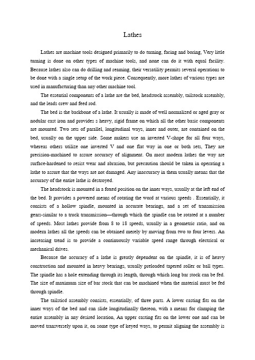
LathesLathes are machine tools designed primarily to do turning, facing and boring, Very little turning is done on other types of machine tools, and none can do it with equal facility. Because lathes also can do drilling and reaming, their versatility permits several operations to be done with a single setup of the work piece. Consequently, more lathes of various types are used in manufacturing than any other machine tool.The essential components of a lathe are the bed, headstock assembly, tailstock assembly, and the leads crew and feed rod.The bed is the backbone of a lathe. It usually is made of well normalized or aged gray or nodular cast iron and provides s heavy, rigid frame on which all the other basic components are mounted. Two sets of parallel, longitudinal ways, inner and outer, are contained on the bed, usually on the upper side. Some makers use an inverted V-shape for all four ways, whereas others utilize one inverted V and one flat way in one or both sets, They are precision-machined to assure accuracy of alignment. On most modern lathes the way are surface-hardened to resist wear and abrasion, but precaution should be taken in operating a lathe to assure that the ways are not damaged. Any inaccuracy in them usually means that the accuracy of the entire lathe is destroyed.The headstock is mounted in a foxed position on the inner ways, usually at the left end of the bed. It provides a powered means of rotating the word at various speeds . Essentially, it consists of a hollow spindle, mounted in accurate bearings, and a set of transmission gears-similar to a truck transmission—through which the spindle can be rotated at a number of speeds. Most lathes provide from 8 to 18 speeds, usually in a geometric ratio, and on modern lathes all the speeds can be obtained merely by moving from two to four levers. An increasing trend is to provide a continuously variable speed range through electrical or mechanical drives.Because the accuracy of a lathe is greatly dependent on the spindle, it is of heavy construction and mounted in heavy bearings, usually preloaded tapered roller or ball types. The spindle has a hole extending through its length, through which long bar stock can be fed. The size of maximum size of bar stock that can be machined when the material must be fed through spindle.The tailsticd assembly consists, essentially, of three parts. A lower casting fits on the inner ways of the bed and can slide longitudinally thereon, with a means for clamping the entire assembly in any desired location, An upper casting fits on the lower one and can be moved transversely upon it, on some type of keyed ways, to permit aligning the assembly isthe tailstock quill. This is a hollow steel cylinder, usually about 51 to 76mm(2to 3 inches) in diameter, that can be moved several inches longitudinally in and out of the upper casting by means of a hand wheel and screw.The size of a lathe is designated by two dimensions. The first is known as the swing. This is the maximum diameter of work that can be rotated on a lathe. It is approximately twice the distance between the line connecting the lathe centers and the nearest point on the ways, The second size dimension is the maximum distance between centers. The swing thus indicates the maximum work piece diameter that can be turned in the lathe, while the distance between centers indicates the maximum length of work piece that can be mounted between centers.Engine lathes are the type most frequently used in manufacturing. They are heavy-duty machine tools with all the components described previously and have power drive for all tool movements except on the compound rest. They commonly range in size from 305 to 610 mm(12 to 24 inches)swing and from 610 to 1219 mm(24 to 48 inches) center distances, but swings up to 1270 mm(50 inches) and center distances up to 3658mm(12 feet) are not uncommon. Most have chip pans and a built-in coolant circulating system. Smaller engine lathes-with swings usually not over 330 mm (13 inches ) –also are available in bench type, designed for the bed to be mounted on a bench on a bench or cabinet.Although engine lathes are versatile and very useful, because of the time required for changing and setting tools and for making measurements on the work piece, thy are not suitable for quantity production. Often the actual chip-production tine is less than 30% of the total cycle time. In addition, a skilled machinist is required for all the operations, and such persons are costly and often in short supply. However, much of the operator’s time is consumed by simple, repetitious adjustments and in watching chips being made. Consequently, to reduce or eliminate the amount of skilled labor that is required, turret lathes, screw machines, and other types of semiautomatic and automatic lathes have been highly developed and are widely used in manufacturing.2 Numerical ControlOne of the most fundamental concepts in the area of advanced manufacturing technologies is numerical control (NC). Prior to the advent of NC, all machine tools ere manually operated and controlled. Among the many limitations associated with manual control machine tools, perhaps none is more prominent than the limitation of operator skills. With manual control, the quality of the product is directly related to and limited to the skills of the operator. Numerical control represents the first major step away from human control of machine tools.Numerical control means the control of machine tools and other manufacturing systems through the use of prerecorded, written symbolic instructions. Rather than operating a machine tool, an NC technician writes a program that issues operational instructions to the machine tool. For a machine tool to be numerically controlled, it must be interfaced with a device for accepting and decoding the programmed instructions, known as a reader.Numerical control was developed to overcome the limitation of human operators, and it has done so. Numerical control machines are more accurate than manually operated machines, they can produce parts more uniformly, they are faster, and the long-run tooling costs are lower. The development of NC led to the development of several other innovations in manufacturing technology:Electrical discharge machining,Laser cutting,Electron beam welding.Numerical control has also made machine tools more versatile than their manually operated predecessors. An NC machine tool can automatically produce a wide of parts, each involving an assortment of widely varied and complex machining processes. Numerical control has allowed manufacturers to undertake the production of products that would not have been feasible from an economic perspective using manually controlled machine tolls and processes.Like so many advanced technologies, NC was born in the laboratories of the Massachusetts Institute of Technology. The concept of NC was developed in the early 1950s with funding provided by the U.S. Air Force. In its earliest stages, NC machines were able to made straight cuts efficiently and effectively.However, curved paths were a problem because the machine tool had to be programmed to undertake a series of horizontal and vertical steps to produce a curve. The shorter the straight lines making up the steps, the smoother is the curve, Each line segment in the steps had to be calculated.This problem led to the development in 1959 of the Automatically Programmed Tools (APT) language. This is a special programming language for NC that uses statements similar to English language to define the part geometry, describe the cutting tool configuration, and specify the necessary motions. The development of the APT language was a major step forward in the fur ther development from those used today. The machines had hardwired logic circuits. The instructional programs were written on punched paper, which was later to be replaced by magnetic plastic tape. A tape reader was used to interpret the instructions written on the tape for the machine. Together, all of this represented a giant step forward in the control of machine tools. However, there were a number of problems with NC at this point in its development.A major problem was the fragility of the punched paper tape medium. It was common for the paper tape containing the programmed instructions to break or tear during a machining process. This problem was exacerbated by the fact that each successive time a part was produced on a machine tool, the paper tape carrying the programmed instructions had to be rerun through the reader. If it was necessary to produce 100 copies of a given part, it was also necessary to run the paper tape through the reader 100 separate tines. Fragile paper tapes simply could not withstand the rigors of a shop floor environment and this kind of repeated use.This led to the development of a special magnetic plastic tape. Whereas the paper carried the programmed instructions as a series of holes punched in the tape, the plastic tape carried the instructions as a series of magnetic dots. The plastic tape was much stronger than the paper tape, which solved the problem of frequent tearing and breakage. However, it still left two other problems.The most important of these was that it was difficult or impossible to change the instructions entered on the tape. To made even the most minor adjustments in a program of instructions, it was necessary to interrupt machining operations and make a new tape. It was also still necessary to run the tape through the reader as many times as there were parts to be produced. Fortunately, computer technology became a reality and soon solved the problems of NC associated with punched paper and plastic tape.The development of a concept known as direct numerical control (DNC) solved the paper and plastic tape problems associated with numerical control by simply eliminating tape as the medium for carrying the programmed instructions. In direct numerical control, machine tools are tied, via a data transmission link, to a host computer. Programs for operating the machine tools are stored in the host computer and fed to the machine tool an needed via the data transmission linkage. Direct numerical control represented a major step forward over punched tape and plastic tape. However, it is subject to the same limitations as all technologies that depend on a host computer. When the host computer goes down, the machine tools also experience downtime. This problem led to the development of computer numerical control.3 TurningThe engine lathe, one of the oldest metal removal machines, has a number of useful and highly desirable attributes. Today these lathes are used primarily in small shops where smaller quantities rather than large production runs are encountered.The engine lathe has been replaced in today’s production shops by a wide variety of automatic lathes such as automatic of single-point tooling for maximum metal removal, andthe use of form tools for finish on a par with the fastest processing equipment on the scene today.Tolerances for the engine lathe depend primarily on the skill of the operator. The design engineer must be careful in using tolerances of an experimental part that has been produced on the engine lathe by a skilled operator. In redesigning an experimental part for production, economical tolerances should be used.Turret Lathes Production machining equipment must be evaluated now, more than ever before, this criterion for establishing the production qualification of a specific method, the turret lathe merits a high rating.In designing for low quantities such as 100 or 200 parts, it is most economical to use the turret lathe. In achieving the optimum tolerances possible on the turrets lathe, the designer should strive for a minimum of operations.Automatic Screw Machines Generally, automatic screw machines fall into several categories; single-spindle automatics, multiple-spindle automatics and automatic chucking machines. Originally designed for rapid, automatic production of screws and similar threaded parts, the automatic screw machine has long since exceeded the confines of this narrow field, and today plays a vital role in the mass production of a variety of precision parts. Quantities play an important part in the economy of the parts machined on the automatic screw machine. Quantities less than on the automatic screw machine. The cost of the parts machined can be reduced if the minimum economical lot size is calculated and the proper machine is selected for these quantities.Automatic Tracer Lathes Since surface roughness depends greatly on material turned, tooling , and feeds and speeds employed, minimum tolerances that can be held on automatic tracer lathes are not necessarily the most economical tolerances.In some cases, tolerances of 0.05mm are held in continuous production using but one cut . groove width can be held to 0.125mm on some parts. Bores and single-point finishes can be held to 0.0125mm. On high-production runs where maximum output is desirable, a minimum tolerance of 0.125mm is economical on both diameter and length of turn.车床车床主要是为了进行车外圆、车端面和镗孔等项工作而设计的机床。
车床机床夹具类外文文献翻译、中英文翻译、外文翻译

中北大学信息商务学院本科毕业设计英文参考资料题目 Lathes系名专业姓名学号指导教师2016年6 月2 日译文标题车床简介原文标题Lathes作者(Serope kalpakjian)译名卡尔帕基安国籍美国原文出处/原文:LathesLathes are machine tools designed primarily to do turning, facing and boring, Very little turning is done on other types of machine tools, and none can do it with equal facility. Because lathes also can do drilling and reaming, their versatility permits several operations to be done with a single setup of the work piece. Consequently, more lathes of various types are used in manufacturing than any other machine tool.The essential components of a lathe are the bed, headstock assembly, tailstock assembly, and the leads crew and feed rod.The bed is the backbone of a lathe. It usually is made of well normalized or aged gray or nodular cast iron and provides s heavy, rigid frame on which all the other basic components are mounted. Two sets of parallel, longitudinal ways, inner and outer, are contained on the bed, usually on the upper side. Some makers use an inverted V-shape for all four ways, whereas others utilize one inverted V and one flat way in one or both sets, They are precision-machined to assure accuracy of alignment. On most modern lathes the way are surface-hardened to resist wear and abrasion, but precaution should be taken in operating a lathe to assure that the ways are not damaged. Any inaccuracy in them usually means that the accuracy of the entire lathe is destroyed.The headstock is mounted in a foxed position on the inner ways, usually at the left end of the bed. It provides a powered means of rotating the word at various speeds . Essentially, it consists of a hollow spindle, mounted in accurate bearings, and a set of transmission gears-similar to a truck transmission—through which the spindle can be rotated at a number of speeds. Most lathes provide from 8 to 18 speeds, usually in a geometric ratio, and on modern lathes all the speeds can be obtained merely by moving from two to four levers. An increasing trend is to provide a continuously variable speed range through electrical or mechanical drives.Because the accuracy of a lathe is greatly dependent on the spindle, it is of heavyconstruction and mounted in heavy bearings, usually preloaded tapered roller or ball types. The spindle has a hole extending through its length, through which long bar stock can be fed. The size of maximum size of bar stock that can be machined when the material must be fed through spindle.The tailsticd assembly consists, essentially, of three parts. A lower casting fits on the inner ways of the bed and can slide longitudinally thereon, with a means for clamping the entire assembly in any desired location, An upper casting fits on the lower one and can be moved transversely upon it, on some type of keyed ways, to permit aligning the assembly is the tailstock quill. This is a hollow steel cylinder, usually about 51 to 76mm(2to 3 inches) in diameter, that can be moved several inches longitudinally in and out of the upper casting by means of a hand wheel and screw.The size of a lathe is designated by two dimensions. The first is known as the swing. This is the maximum diameter of work that can be rotated on a lathe. It is approximately twice the distance between the line connecting the lathe centers and the nearest point on the ways, The second size dimension is the maximum distance between centers. The swing thus indicates the maximum work piece diameter that can be turned in the lathe, while the distance between centers indicates the maximum length of work piece that can be mounted between centers.Engine lathes are the type most frequently used in manufacturing. They areheavy-duty machine tools with all the components described previously and have power drive for all tool movements except on the compound rest. They commonly range in size from 305 to 610 mm(12 to 24 inches)swing and from 610 to 1219 mm(24 to 48 inches) center distances, but swings up to 1270 mm(50 inches) and center distances up to3658mm(12 feet) are not uncommon. Most have chip pans and a built-in coolant circulating system. Smaller engine lathes-with swings usually not over 330 mm (13 inches ) –also are available in bench type, designed for the bed to be mounted on a bench on a bench or cabinet.Although engine lathes are versatile and very useful, because of the time required for changing and setting tools and for making measurements on the work piece, thy are not suitable for quantity production. Often the actual chip-production tine is less than 30% of the total cycle time. In addition, a skilled machinist is required for all the operations, and such persons are costly and often in short supply. However, much of the operator’s time is consumed by simple, repetitious adjustments and in watching chips being made. Consequently, to reduce or eliminate the amount of skilled labor that is required, turret lathes, screw machines, and other types of semiautomatic and automatic lathes have been highly developed and are widely used in manufacturing.2 Numerical ControlOne of the most fundamental concepts in the area of advanced manufacturing technologies is numerical control (NC). Prior to the advent of NC, all machine tools ere manually operated and controlled. Among the many limitations associated with manual control machine tools, perhaps none is more prominent than the limitation of operator skills. With manual control, the quality of the product is directly related to and limited to the skills of the operator. Numerical control represents the first major step away from human control of machine tools.Numerical control means the control of machine tools and other manufacturing systems through the use of prerecorded, written symbolic instructions. Rather than operating a machine tool, an NC technician writes a program that issues operational instructions to the machine tool. For a machine tool to be numerically controlled, it must be interfaced with a device for accepting and decoding the programmed instructions, known as a reader.Numerical control was developed to overcome the limitation of human operators, and it has done so. Numerical control machines are more accurate than manually operated machines, they can produce parts more uniformly, they are faster, and the long-run tooling costs are lower. The development of NC led to the development of several other innovations in manufacturing technology:Electrical discharge machining,Laser cutting,Electron beam welding.Numerical control has also made machine tools more versatile than their manually operated predecessors. An NC machine tool can automatically produce a wide of parts, each involving an assortment of widely varied and complex machining processes. Numerical control has allowed manufacturers to undertake the production of products that would not have been feasible from an economic perspective using manually controlled machine tolls and processes.Like so many advanced technologies, NC was born in the laboratories of the Massachusetts Institute of Technology. The concept of NC was developed in the early 1950s with funding provided by the U.S. Air Force. In its earliest stages, NC machines were able to made straight cuts efficiently and effectively.However, curved paths were a problem because the machine tool had to be programmed to undertake a series of horizontal and vertical steps to produce a curve. The shorter the straight lines making up the steps, the smoother is the curve, Each line segment in the steps had to be calculated.This problem led to the development in 1959 of the Automatically Programmed Tools (APT) language. This is a special programming language for NC that uses statementssimilar to English language to define the part geometry, describe the cutting tool configuration, and specify the necessary motions. The development of the APT language was a major step forward in the fur ther development from those used today. The machines had hardwired logic circuits. The instructional programs were written on punched paper, which was later to be replaced by magnetic plastic tape. A tape reader was used to interpret the instructions written on the tape for the machine. Together, all of this represented a giant step forward in the control of machine tools. However, there were a number of problems with NC at this point in its development.A major problem was the fragility of the punched paper tape medium. It was common for the paper tape containing the programmed instructions to break or tear during a machining process. This problem was exacerbated by the fact that each successive time a part was produced on a machine tool, the paper tape carrying the programmed instructions had to be rerun through the reader. If it was necessary to produce 100 copies of a given part, it was also necessary to run the paper tape through the reader 100 separate tines. Fragile paper tapes simply could not withstand the rigors of a shop floor environment and this kind of repeated use.This led to the development of a special magnetic plastic tape. Whereas the paper carried the programmed instructions as a series of holes punched in the tape, the plastic tape carried the instructions as a series of magnetic dots. The plastic tape was much stronger than the paper tape, which solved the problem of frequent tearing and breakage. However, it still left two other problems.The most important of these was that it was difficult or impossible to change the instructions entered on the tape. To made even the most minor adjustments in a program of instructions, it was necessary to interrupt machining operations and make a new tape. It was also still necessary to run the tape through the reader as many times as there were parts to be produced. Fortunately, computer technology became a reality and soon solved the problems of NC associated with punched paper and plastic tape.The development of a concept known as direct numerical control (DNC) solved the paper and plastic tape problems associated with numerical control by simply eliminating tape as the medium for carrying the programmed instructions. In direct numerical control, machine tools are tied, via a data transmission link, to a host computer. Programs for operating the machine tools are stored in the host computer and fed to the machine tool an needed via the data transmission linkage. Direct numerical control represented a major step forward over punched tape and plastic tape. However, it is subject to the same limitations as all technologies that depend on a host computer. When the host computer goes down, the machine tools also experience downtime. This problem led to the development of computernumerical control.3 TurningThe engine lathe, one of the oldest metal removal machines, has a number of useful and highly desirable attributes. Today these lathes are used primarily in small shops where smaller quantities rather than large production runs are encountered.Th e engine lathe has been replaced in today’s production shops by a wide variety of automatic lathes such as automatic of single-point tooling for maximum metal removal, and the use of form tools for finish on a par with the fastest processing equipment on the scene today.Tolerances for the engine lathe depend primarily on the skill of the operator. The design engineer must be careful in using tolerances of an experimental part that has been produced on the engine lathe by a skilled operator. In redesigning an experimental part for production, economical tolerances should be used.Turret Lathes Production machining equipment must be evaluated now, more than ever before, this criterion for establishing the production qualification of a specific method, the turret lathe merits a high rating.In designing for low quantities such as 100 or 200 parts, it is most economical to use the turret lathe. In achieving the optimum tolerances possible on the turrets lathe, the designer should strive for a minimum of operations.Automatic Screw Machines Generally, automatic screw machines fall into several categories; single-spindle automatics, multiple-spindle automatics and automatic chucking machines. Originally designed for rapid, automatic production of screws and similar threaded parts, the automatic screw machine has long since exceeded the confines of this narrow field, and today plays a vital role in the mass production of a variety of precision parts. Quantities play an important part in the economy of the parts machined on the automatic screw machine. Quantities less than on the automatic screw machine. The cost of the parts machined can be reduced if the minimum economical lot size is calculated and the proper machine is selected for these quantities.Automatic Tracer Lathes Since surface roughness depends greatly on material turned, tooling , and feeds and speeds employed, minimum tolerances that can be held on automatic tracer lathes are not necessarily the most economical tolerances.In some cases, tolerances of 0.05mm are held in continuous production using but one cut . groove width can be held to 0.125mm on some parts. Bores and single-point finishes can be held to 0.0125mm. On high-production runs where maximum output is desirable, a minimum tolerance of 0.125mm is economical on both diameter and length of turn。
机械设计外文翻译

机械设计外文翻译Mechanical DesignMechanical design is a branch of engineering that deals with the creation and development of machines and mechanical systems. It involves the application of principles and methodologies from various disciplines such as physics, materials science, and mathematics to design machines that are safe, reliable, and efficient.Mechanical design is a crucial aspect of engineering because it is responsible for creating machines that are used in a wide range of industries. From automobiles and airplanes toindustrial machinery and consumer products, mechanical design plays a vital role in the development of these machines. It requires a deep understanding of the principles of mechanics, thermodynamics, and materials science, as well as a creative and problem-solving mindset.In addition to designing machines, mechanical design also involves considerations of cost, safety, and environmental impact. Engineers must balance the performance and functionality of a machine with its cost and the impact it may have on the environment. They must also ensure that the machine is safe to use and meets all relevant regulations and standards. This often involves conducting risk assessments and performing stress andfailure analysis to identify potential issues and ensure the machine meets the required safety and quality standards.。
机械工程专业毕业设计外文翻译

英文原文名Lthes中文译名车床10/ 1中文译文:车床车床主要是为了进行车外圆、车端面和镗孔等项工作而设计的机床。
车削很少在其他种类的机床上进行,而且任何一种其他机床都不能像车床那样方便地进行车削加工。
由于车床还可以用来钻孔和铰孔,车床的多功能性可以使工件在一次安装中完成几种加工。
因此,在生产中使用的各种车床比任何其他种类的机床都多。
车床的基本部件有:床身、主轴箱组件、尾座组件、溜板组件、丝杠和光杠。
床身是车床的基础件。
它能常是由经过充分正火或时效处理的灰铸铁或者球墨铁制成。
它是一个坚固的刚性框架,所有其他基本部件都安装在床身上。
通常在床身上有内外两组平行的导轨。
有些制造厂对全部四条导轨都采用导轨尖朝上的三角形导轨(即山形导轨),而有的制造厂则在一组中或者两组中都采用一个三角形导轨和一个矩形导轨。
导轨要经过精密加工以保证其直线度精度。
为了抵抗磨损和擦伤,大多数现代机床的导轨是经过表面淬硬的,但是在操作时还应该小心,以避免损伤导轨。
导轨上的任何误差,常常意味着整个机床的精度遭到破坏。
主轴箱安装在内侧导轨的固定位置上,一般在床身的左端。
它提供动力,并可使工件在各种速度下回转。
它基本上由一个安装在精密轴承中的空心主轴和一系列变速齿轮(类似于卡车变速箱)所组成。
通过变速齿轮,主轴可以在许多种转速下旋转。
大多数车床有8~12种转速,一般按等比级数排列。
而且在现代机床上只需扳动2~4个手柄,就能得到全部转速。
一种正在不断增长的趋势是通过电气的或者机械的装置进行无级变速。
由于机床的精度在很大程度上取决于主轴,因此,主轴的结构尺寸较大,通常安装在预紧后的重型圆锥滚子轴承或球轴承中。
主轴中有一个贯穿全长的通孔,长棒料可以通过该孔送料。
主轴孔的大小是车床的一个重要尺寸,因此当工件必须通过主轴孔供料时,它确定了能够加工的棒料毛坯的最大尺寸。
数字控制的机器比人工操纵的机器精度更高、生产出零件的一致性更好、生产速度更快、而且长期的工艺装备成本更低。
数控车床主轴部件机械外文文献翻译、中英文翻译、外文翻译

数控车床主轴部件机械外文文献翻译、中英文翻译、外文翻译数控车床主轴部件车床是一种主要用于加工旋转表面和平整边缘的机床。
根据使用目的、结构、刀具数量和自动化程度的不同,车床可以分为普通车床、万能车床、转塔车床、立式车床、自动车床和特殊车床。
虽然车床种类繁多,但它们在结构和操作原理上具有共同特性。
普通车床是最常用的代表类型,下面将介绍普通车床的主要部分。
车床床身是车床的主骨架,由两个垂直支柱上的水平横梁组成。
为减振,它通常由灰铸铁或球墨铸铁铸造而成。
车床床身上有导轨,可以让大拖板轻松纵向滑动。
车床床身的高度应适当以方便技师工作。
主轴箱固定在车床床身的左侧,包括轴线平行于导轨的主轴。
主轴通过齿轮箱驱动,齿轮箱可以提供多种不同的速度(通常是6到18速)。
现代车床有些采用无级调速主轴箱,采用摩擦、电力或液压驱动。
主轴往往是中空的,纵向有一通孔,可以通过此孔进给棒料。
同时,此孔为锥形表面,可以安装普通车床顶尖。
主轴外表面是螺纹,可以安装卡盘、花盘或类似的装置。
尾架总成包括底座、尾架体和套筒轴。
底座是能在车床床身上沿导轨滑动的铸件,有定位装置,可以让整个尾架根据工件长度锁定在任何需要位置。
使用手轮和螺杆,与螺杆啮合的是一固接在套筒轴上的螺母。
套筒轴开口端的孔是锥形的,能安装车床顶尖或诸如麻花钻和镗杆之类的工具。
套筒轴通过定位装置能沿着它的移动路径被锁定在任何点。
大拖板的主要功能是安装刀具和产生纵向和/或横向进给。
它实际上是一由车床床身V形导轨引导的、能在车床床身主轴箱和尾架之间滑动的H形滑块。
大拖板可以手动或通过溜板箱和光杆(进给杆)或丝杆(引导螺杆)机动。
本文介绍了在传统普通车床上进行的各种机加工作业。
但是,需要注意的是现代计算机数控车床具有更多的功能,并且可以进行其他操作,例如仿型。
圆柱面车削是所有车床操作中最简单也是最常见的。
工件旋转一整圈产生一个圆心落在车床主轴上的圆;由于刀具的轴向进给运动,这种动作重复许多次。
车床机床改造外文文献翻译、中英文翻译、外文翻译
本科毕业论文中英文翻译学生姓名:所在院系:机电学院所学专业:机械设计制造及其自动化车床车床主要是为了进行车外圆、车端面和镗孔等项工作而设计的机床。
车削很少在其他种类的机床上进行,而且任何一种其他机床都不想车床那样方便地进行车削加工。
由于车床还可以用来钻孔和铰孔,车床的多功能性可以使工件在一次装夹中进行几种加工。
因此,在生产中使用的各种车床比任何种类的机床都多。
普通车床:普通车床作为最早的金属切削机床中的一种,目前仍然有许多有用的和人们所需要的特性。
现在,这些机床主要用在规模较小的工厂中,进行小批量的生产,而不是进行大批量的生产。
普通车床的加工偏差主要取决于操作者的技术熟练程度。
设计工程师应该认真的确定由熟练工人在普通车床上加工的试验零件的公差。
在把试验零件重新设计为生产零件时,应该选用经济的公差。
转塔车床:对生产加工设备来说,目前比过去更着重评价是否具有精确的和快速的重复加工能力。
应用这个标准来评价具体的加工方法,转塔车床可以获得较高的质量评定。
在为小批量的零件(100—200件)设计加工方法时,采用转塔车床是经济的。
为了在转塔车床上获得极可能小的公差值,设计人员应该尽量将加工工序的数目减至最少。
自动螺丝车床:自动螺丝车床通常被分为以下几种类型:单轴自动、多轴自动和自动夹紧车床。
自动螺丝车床最初是用来对螺钉和类似的带有螺纹的零件进行自动化和快速加工的。
但是。
这种车床的用途早就超过了这个狭窄的范围。
现在,它在许多类型的精密零件的大批量生产中起着重要的作用。
车床的基本部件有:床身、主轴箱部件、尾架部件、溜板部件丝杠和光杠。
床身是车床的基础件。
它通常是由于经过充分正火或时效处理的灰铸铁或者球墨铸铁之城。
它是一个兼顾的刚性框架,所有其他基本部件都安装在车床身上。
通常在床身上有内外讲足平行的导轨。
有些制造厂对全部四条导轨都采用导轨尖顶朝上的三角形导轨(即山形导轨),而有的制造厂则在一组中或者两组中都采用一个三角形导轨和一个矩形导轨。
Mechanical-Design机械设计毕业论文外文文献翻译及原文
毕业设计(论文)外文文献翻译文献、资料中文题目:机械设计文献、资料英文题目:Mechanical Design文献、资料来源:文献、资料发表(出版)日期:院(部):专业:班级:姓名:学号:指导教师:翻译日期: 2017.02.14外文资料翻译译文机械设计摘要:机器是由机械装置和其它组件组成的。
它是一种用来转换或传递能量的装置,例如:发动机、涡轮机、车辆、起重机、印刷机、洗衣机、照相机和摄影机等。
许多原则和设计方法不但适用于机器的设计,也适用于非机器的设计。
术语中的“机械装置设计”的含义要比“机械设计”的含义更为广泛一些,机械装置设计包括机械设计。
在分析运动及设计结构时,要把产品外型以及以后的保养也要考虑在机械设计中。
在机械工程领域中,以及其它工程领域中,所有这些都需要机械设备,比如:开关、凸轮、阀门、船舶以及搅拌机等。
关键词:设计流程设计规则机械设计设计流程设计开始之前就要想到机器的实际性,现存的机器需要在耐用性、效率、重量、速度,或者成本上得到改善。
新的机器必需具有以前机器所能执行的功能。
在设计的初始阶段,应该允许设计人员充分发挥创造性,不要受到任何约束。
即使产生了许多不切实际的想法,也会在设计的早期,即在绘制图纸之前被改正掉。
只有这样,才不致于阻断创新的思路。
通常,还要提出几套设计方案,然后加以比较。
很有可能在这个计划最后决定中,使用了某些不在计划之内的一些设想。
一般的当外型特点和组件部分的尺寸特点分析得透彻时,就可以全面的设计和分析。
接着还要客观的分析机器性能的优越性,以及它的安全、重量、耐用性,并且竞争力的成本也要考虑在分析结果之内。
每一个至关重要的部分要优化它的比例和尺寸,同时也要保持与其它组成部分相协调。
也要选择原材料和处理原材料的方法。
通过力学原理来分析和实现这些重要的特性,如那些静态反应的能量和摩擦力的最佳利用,像动力惯性、加速动力和能量;包括弹性材料的强度、应力和刚度等材料的物理特性,以及流体润滑和驱动器的流体力学。
- 1、下载文档前请自行甄别文档内容的完整性,平台不提供额外的编辑、内容补充、找答案等附加服务。
- 2、"仅部分预览"的文档,不可在线预览部分如存在完整性等问题,可反馈申请退款(可完整预览的文档不适用该条件!)。
- 3、如文档侵犯您的权益,请联系客服反馈,我们会尽快为您处理(人工客服工作时间:9:00-18:30)。
自动车床系统设计的研究1摘要:车床数字化设计系统的开发,是通过工程知识相关的技术和产品的参数化设计技术之间的融合发展起来的。
设计系统的框架在细节上表现为主控模块,初始化模块,三维和二维的更新管理模块,知识管理模块和知识库。
本文对系统的关键技术设计比如知识挖掘与分类、自动变换结构设计、建立数据库、自动设计变结构与车床设计导航进行了进一步研究。
最后,本文对自动设计系统的界面和设计过程进行了详细的介绍。
关键词:车床;知识重组;自动设计系统一、导言新一代的数码解决方案使技术创新能在不同的环境下进行,并且减少整个产品的开发周期、节省时间和提高产品质量。
目前,在消费产品的研发中采用不同的方法进行快速设计并取得了成果,然而对于商业产品却很少受到注意,特别是机床,目前尚未对其进行研究。
我们的第二个目的是衡量不同的人群在同一个测试中表现出来的不同的敏感性。
该阶段的研究是很详尽的,包括:对描述的选择,对图像的选择和对所参与人群的选择。
结果表明,这些技术也适用于机床的设计,不同的群体对机器的认识也是不同的,在某些方面的差异,并不仅限于用户与专家在相关的行业中这种差异依然存在,在相关行业中通常是根据技术规格来决定机器的购买或使用。
这些技术规范是可以测量的,但机器一些重要的参数,如便捷性,安全性,耐用性等却不那么容易衡量和比较。
本文表明,语义差别的方法是用来衡量这些性能的一种可能途径。
车床的设计是复杂的过程,在设计的过程中很多知识都是必要的。
在生产的过程当中,不同的知识在不同产品不同开发阶段中起不同的作用。
许多新产品是在原有产品的基础上设计发展起来的。
车床设计行业的设计成果中,几乎60%是由组件设计的重组制作而成的,30%是根据过去的产品修订的。
在本文中,我们提出了一个车床设计技术,采用NX平台,建立了车床设计的专门知识库,并融入新产品的设计理念和成熟的设计经验,运用先进的开发工具,如UG/ Open API,UIStyler,MenuScript 。
这种新方法可以有效地提供设计质量保证,缩短产品设计周期,提高设计效率和车床水平,并且对汽车玻璃行业有重大影响力。
车床设计系统应用所学到的知识来完成车床快速设计。
设计系统过程中所需要应用的知识包括成熟的车床产品,车床设计标准的有关技术数据,专业知识,丰富的设计经验和最新的研究成果。
在产品设计周期中,嵌入式系统需要设计论证和设计指导机制。
而且设计师只需要输入参数并由人机界面通过索引的帮助下符合客户要求即可。
这些参数包括车1原文出处:Elsevier Science Direct Onsite 作者:Shurong Huang, Defang Liu, and Bin Wang床厚度,钳板的长度等,推理机将与每一个规则所规定的条件进行比较,如果它们匹配,则该规则的结论将作为一个新的事实被添加到设计知识库。
根据发展过程中的需求,该系统分为以下功能模块。
系统开发的目的是通过知识重组来实现自动车床的设计,提高产品的设计质量和效率。
以检查轨距为导向的车床设计系统的设计过程可分为:需求分析阶段,初步设计阶段,详细设计阶段和功能的改进、测试阶段。
在需求分析阶段,经过仔细分析和对话,系统能够根据用户设置的钳板曲线设计车床形状,实现自动车床重点部分的设计,自动创建一套车床。
在选择开发工具方面,我们考虑了用户的要求以及对一些工具的熟练程度,最终决定采用UG NX5.0和Visual Studio 2005作为开发平台。
在详细设计阶段,我们先在UG互动的环境一步一步进行设计,然后由应用程序最终完成。
该方案的主体部分仅仅是在前文提到的上述阶段实现的,但是在应用过程中一些细节没有完全考虑进去,在提高产品性能的阶段,我们做了详细的测试,一些错误已经得到纠正。
这有助于使系统更加稳定和完善。
A. 设计知识表示有效的知识表示方法是进行知识融合和知识重组的关键。
目前,常见的知识表示方法,包括动词的逻辑表示,产生式规则,帧表示,面向对象的表示等,本文中生成型车床的设计规则说明如下:<Rule>∷=(IF{<Condition>} THEN {<Result>})< Condition >∷=(<Expression>∣<Fact>)< Expression >∷=({<Variant><Verb><Attribute>})< Fact >∷=({<Fact item>})< Verb >∷=(< > = + - * / sin、cos、tg、log …)< Attribute value>∷=({< Variant >∣<Value>})<Conclusion>∷=({<Presentation>∣<Operation>})< Presentation >∷=({< Presentation item>})<Operation>∷=({<Operating function>})例如,在嵌入块成型,两平面之间的关系(平行或交叉)(P1和P2)的车床设计是由法线向量(V1和V2)来判断。
在这个例子中,三个规则可以从规则库选取,有如下几点:规则1:如果V1×V2=0而且P1的矢量方向和P2是相同的,则P1∥P2和P1和P2具有相同的向量方向。
规则2:如果V1×V2=0和P1的矢量方向和P2是相反的,则P1∥P2和P1和P2有相反的向量方向。
规则3:如果V1×V2≠0,P1的矢量方向和P2是不同的,则P1和 P2的彼此相交。
车床设计的框架表示。
帧,是另外一种知识表示形式的数据结构,每帧作为一个知识单元,由马文•明斯基在1975年提出。
详细的形式在下面的例子中说明:<Frame>……Slot name I:Flank name i1 (Value i11, Value i12, …)Flank name i2 (Value i21, Value i22, …)Slot name J:< Frame name>…Slot name K:<Additive course>车床设计案例检索。
最创新的产品设计往往都基于以前的经验和理论,因此,新产品许多地方继承了原有产品的设计。
由于大多数产品的设计不是原来的,但以前的车床设计规则或流程仍可能会有所帮助。
在本文中,我们提出了使用基于案例的推理方法来实现产品的车床设计的理念。
我们采用动态存储模型来表示系统中的案例。
这意味着各种案件根据它们的一般特征来组织,并根据他们之间的分歧指数来区分它们。
案例库通过起关键作用的关系数据库技术的产品ID建立起来。
SQL可作为初步检索句子。
例如,如果我们要查询案例,可用下面的伪代码。
SELECT case number FROM case baseWHERE product ID =‘input value’为了作进一步的分析,车床设计要求能够对其进行修改,以便适应自动探索设计空间。
如果修改只影响某些参数的设置值而不触及问题的结构,我们就说它是一个参数化设计。
对于过程流相关的任务级应用,进程中没有结构性的变化,即,结构设计是被限制的。
对于序列中不同步骤的不同流程之间的比较,被映射到的一个给定步骤的影响在某些参数值的调节方面存在差异。
例如,如果是两个不同的进程选项之间的比较,对其中一个植入额外的步骤,另一没有此步骤,那么在植入的步骤参数值设置非常低的情况下就能很方便地建模,而在实际应用中完全没有这一步。
为了实现一般的参数化设计的产品,我们首先需要对产品进行分析,并确定组件之间的相互关系,包括:车床设计的关系、几何关系和参数的关系。
下一步,在数据,帧,条件语句,以及先进的程序语言的形成过程中,需要对相关工程知识进行收集、整理、一般化处理、提取和存储。
然后,需要对所有对产品性能有影响的工程参数加以界定,这可以用来采用模糊分析的方法通过工程参数对订单要求的其他类型的自动车床进行检验。
图1显示了车床的不同知识表达方式。
基本知识:基本车床知识包括:1)客户对车床的使用要求;2)对客户潜在需求的预测;3)相关的部件和组件设计的国际国内标准;4)以往的设计案例;5)在特殊的环境下对产品性能的要求;6)对不同的部件和组件的设计要求;7)车床不同零部件之间的设计联系和几何位置关系;8)不同材质和规格零件的特性。
通过对自动车床基本知识的分析和研究,我们已经制定出总体结构的主要控制参数和大体的设计规则以及产品设计知识库。
产品结构知识:该系统采用自上而下的设计方法来开发产品型号。
在建立产品模型之前就应该确定出产品的结构,因此应该对影响产品结构的知识进行确认、分析。
产品结构的知识,主要包括尺寸,形状,车床的设计尺寸和不同零部件之间的位置关系。
据NX平台的特点,产品的整体框架知识包括基准面产品结构知识,车床零部件之间的设计限制,以及基于功能的组件的布局等。
组成车床检验设计的控制结构建立在NX平台上的产品草图拓扑之上。
产品设计过程的知识:产品设计过程的知识主要包括产品设计流程、鉴定原则等,反映了基本知识和产品结构知识之间的相互依存关系。
在基本知识和产品结构知识间联系的基础上,采用产品开发工具UFun来实现产品设计的智能导航和自动可变产品结构设计。
B.可变结构的自动设计作为一个典型的串行转化产品,自动车床的结构形式随用户需求的变化而变化。
本文采用一些先进的技术解决可变结构问题,如维度的驱动技术,限制驱动技术,几何对象驱动技术和数据制约技术。
毕业设计(论文)外文翻译原文Research on Lathe Automatic Design System Abstract—A lathe digital design system was developed through the integration between knowledge-engineering-related technology and product parametric design technology. The frame of the design system was expressed in detail such as main control module, initialization module, update management module of 3D and 2D, knowledge management module and knowledge library. The key technologies of the system design such as Knowledge mining and classification, automatic design of transform structures, establishing model database, automatic design of variable structure, and lathe design navigator were further studied in the paper. Finally, the automatic design system interface and the design process were introduced in detail.Keywords-lathe; knowledge reuse; automatic design systemI. INTRODUCTIONThe new age of digital solutions empowers innovation through different environments and transforms the entire product cycle development to reduce waste and lead time, all involved with the aiming for quality. Nowadays, different approaches to rapid design are being applied to consumer products with successful results, but commercial products have generally received less attention and machine tools in particular have not yet been studied. [1-3] Our second objective is to measure the different sensitivities that the different groups of the population have in answering the same test. The stages of the study are detailed: selection of descriptors or adjectives, selection of images and choice of the population takingpart. The results show that these techniques are applicable to machine tool design, that the perception of the different groups of the population involved with machine centre is different in certain ways, and that the differences are not limited to users vs. experts. Relevance to industry; [4] Decisions on which machine to buy or use are usually based on technical specifications. These technical specifications can be measured, yet some important requirements of the machines, such as ease of use, safety, robustness, etc. are not so easily measurable and comparable. This paper shows that the Semantic Differential approach may be a tool for measuring perception of those aspects.Lathe design is complicated procession in which lots of knowledge is necessary. The knowledge plays different parts on the different steps of product development. Many new products are developed on the base of existed design knowledge and effects. In lathe design industry, almost 60% of the design works are based on the reuse of existed component design and 30% of them are based on the revision of past parts [4-8]. In this paper we put forward an lathe design technique that adopts NX platform, establishes a special knowledge library of lathe design and merges existed and mature design experience into the design procession of new products with developing tools such as UG/Open API, UIStyler, MenuScript.This new way can effectively provide design quality supports, shorten product design period, improve the design efficiency and level of lathe, and have a significant influence on auto glass industry.II. PREPARE YOUR PAPER BEFORE STYLINGThe lathe design system applies acquired knowledge to complete rapid design of lathe. The knowledge that is applied in the design system includes mature lathe products, relevant engineering data of lathe design standard, expertise, accumulated design experience and latest research effects. During the product design period, the system is embedded with design reasoning and design course guide mechanism. And designers only need to input parameters demanded by the customers through human-computer interface with the help of guider of design procession. These parameters include lathe thickness, clamp board length, etc. The reasoning machine will compare the facts with the condition part of every rule, if they match well, then the conclusion part of the rule will be added into the design knowledge library as a new fact. According to the demands of the development course, the system is divided into following functional modules. The aim of the development of the system is to realize repaid design of lathe based on knowledge reuse, and improve the design quality and efficiency of the product. The design course of latheinspection- gauge-oriented design system can be divided into: requirements analysis phase, preliminary design phase, detailed design phase and function improving and testing phase. During the requirement analysis phase and after careful analysis and conversation, the function of the system is focused on being able to automatically create a set of lathe in accordance with the shape of lathe and clamp board curve set by user and achieving automatic lathe design with standard parts.In terms of choosing development tools, we have considered user’s requirements and proficiency degree toward some tools, and have decided to adoptUG NX5.0 and Visual Studio 2005 as the development platform to develop the system at last. During the detailed design phase, we get it done in the UG interactive environment step by step first, and then by applying program. The main body of the program is only achieved during the phases mentioned above and some details in applying course have not been considered completely, during the function improving phase we made detailed tests, through which some errors have been corrected. This helps keep the system more stable and perfect.A. Design knowledge representationEffective knowledge representation method is the key in implementing knowledge fusion and knowledge reuse. At present, common knowledge representation methods include verb logic representation, generating type rules, frame representation, object-oriented representation, etc. In this paper generating type lathe design rules are described as follows:<Rule>∷=(IF{<Condition>} THEN {<Result>})< Condition >∷=(<Expression>∣<Fact>)< Expression >∷=({<Variant><Verb><Attribute>})< Fact >∷=({<Fact item>})< Verb >∷=(< > = + - * / sin、cos、tg、log …)< Attribute value>∷=({< Variant >∣<Value>})<Conclusion>∷=({<Presentation>∣<Operation>})< Presentation >∷=({< Presentation item>})<Operation>∷=({<Operating function>})For example, in the lathe design of embedding block and molding, therelationship (parallel or intersecting) of the two planes (P1 and P2) are judged by the normal vectors (V1 and V2). In this example, three rules can be procured from the rules library and they are as follows:Rule1: IF V1×V2=0 AND the vector directions of P1 andP2 are the same.THEN P1 ∥P2 AND P1 and P2 have the same vectordirections.Rule2: IF V1×V2=0 AND the vector directions of P1 andP2 are opposite.THEN P1 ∥P2 AND P1 and P2 have the opposite vectordirections.Rule3: IF V1×V2≠0 AND the vector directions of P1 andP2 are different.THEN P1and P2 intersects with each other.Lathe design Frame Representation. Frame, put forward by Marvin Minsky in 1975, is another data structure of knowledge representation. Every frame is looked at as a knowledge unit. The detailed form is shown in the following example: <Frame>……Slot name I:Flank name i1 (Value i11, Value i12, …)Flank name i2 (Value i21, Value i22, …)Slot name J:< Frame name>…Slot name K:<Additive course>Lathe design Cases Retrieval. Most innovative products are designed based on previous experience and theory, thus, many parts of the new product design are inherited from the old product design. Since most design of products are not original, previous lathe design rules or processes may be helpful. In this paper we present using a case-based reasoning method to implement product lathe design.We adopt dynamic storage models to represent cases in the system. This means all kinds of cases are organized based on their general characteristics and distinguished according to the index of their differences. The case library is built through a relation database technique where the product ID acts as the key. There SQL is available as the preliminary retrieval sentence. For instance, if we want to inquire a case, the following pseudo code is available.SELECT case number FROM case baseWHERE product ID =‘input value’For further analysis, a design has to be able to be modified in order to be subjected to automatic exploration of the design space. If the modification affects only the value of certain parameter settings while leaving the structure of the problem untouched, we speak of a parameterized design [9-12]. Forprocess-flow related task-level applications, no structural changes in the process flow, i.e., the structure of the design, are admitted. In the case where comparisons between process flows with different step sequences have are to be made, the difference in the sequence has to be mapped to differences in some parameter values thatmodulate the impact of a given step.[13][14] For example, if a comparison is to be made between two different process options, one including an additional implantation step that the other one is lacking, the problem is most conveniently modeled by using a very low value for the dose parameter of the implantation step in the flow that, in reality, entirely lacks that step.To realize the general parameterized design of the product, we first need to analyze the product, and determine the interrelation of the components, including: lathe design relationship, geometric relationship, and parametric relationship. Next, the relevant engineering knowledge need to be collected, arranged, generalized, abstracted and stored in the forms of data, frame, conditional sentence, and advanced program languages. [15-19]. Then, all influential engineering parameters of the product performance need to be defined which may be vague engineering parameters or other type’s order-configured auto lathe inspection. Fig. 1 illustrates the different knowledge expression way of the lathe.B asic knowledge: The Basic knowledge of lathe includes: 1) Customer’s personal using requirement to lathe; 2) Customer’s potential demands prediction; 3) International and domestic standards for related parts and component design; 4) Previous design case; 5) Products’ performance re quisition under a special environment; 6) Design requisition of different parts and component; 7) The lathe design relationship and geometric position among different parts and components;8) The characters of parts’ materials and specifications. Through t he analysis and research on the basic knowledge of the auto lathe, we have drawn out the main control parameters of the general structure and generalized the rules and facts ofthe product design knowledge library.P roduct structure knowledge: This syste m adopts topdown- based design method to develop product model. The product structure should be determined before the establishment of product model, so the knowledge that influences product structure should be analyzed and determined. Product structure knowledge mainly includes out-shape dimensions, lathe design dimensions and position relationships between different parts and components. According to the characters of NX platform, the whole framework knowledge of the product consists of datum plane of product structure knowledge, lathe design restriction among parts, and feature-based component arrangement, etc. The control structure of the lathe inspection design is established based on the topology of product sketches on the NX platform.Knowledge of product design process: The knowledge of product design process mainly includes product design flow, appraisement principles, etc. and reflects the interdependence relationship between basic knowledge and product structure knowledge. On the base of the interlinkage of basic knowledge and product structure knowledge, product developing tool UFun is used to achieve product design intelligent navigation and automatic design of variable product structure.B. Automatic design of variable structureAs a typical serial transforming product, the structure form of auto lathe changes with requirement change of users. In this paper some advanced techniques are adopted to tackle the variable structure issues, such as the dimension-drivingtechnique, restriction-driving technique, geometric objects driving technique and data restraining technique.。