日本LookSilorD打板软件说明书
华美商桥 Premier 手机 App 用户指南说明书

华美商桥® Premier(business Bridge®Premier)手机App用户指南2022 年 4月目录企业网上银行手机App概览 (3)支持的设备 (3)IBM Security® Trusteer® (3)下载手机App (3)登录页面及系统菜单 (4)账户资料 (5)核准付款及模版 (7)转账 (9)支票服务 (10)支付账单 (11)用户管理 (12)其他仪表板小工具 (13)手机App功能 (14)保安编码器核准 (15)激活保安编码器App (15)企业网上银行手机App 概览本指南介绍了华美商桥® Essentials (business Bridge®Essentials )及华美商桥® Premier (business Bridge®Premier )企业网上银行手机App 的主要功能,方便您随时在手机上查看账户、交易、通知,发起和核准转账与付款,以及查询银行地址等。
支持的设备Apple iPhones® 及 iPads®操作系统: iOS 11 及更新的版本。
Android™ 设备操作系统: Android 9.0 及更新的版本。
IBM Security ® Trusteer ®Trusteer 是一款轻量级软件,可保护您的设备免受恶意软件攻击。
当您通过手机App 登录华美商桥® Premier (business Bridge®Premier )时,您的网上银行账号和登录凭证会受到保护。
下载手机App在手机或其他移动设备上,请在 Google Play™ 或 Apple App Store™ 中查找“East West Bank ”,并选择蓝色的 East West Bank Business Mobile App 下载。
服装生产管理附件4--衣拿吊挂系统软件使用手册

衣拿吊挂系统软件操作使用手册I N A H a n g e r S y s t e m V e r6双星新加坡机械私人有限公司T W I N S T A R S I N G A P O R E M A C H I N E R Y P T E.,L T D版权所有©2004-2008h t t p://w w w.t w i n s t a r-g r o u p.c o m第一章第一章 系统概述系统概述1.1硬件配置要求硬件配置要求配置最低要求配置最低要求::主板: 配有串口、并口的电脑主板 CPU : Intel Pentium 4 3.0GHz 内存: DDR 1GB硬盘: 80GB 7200转硬盘(串并口均可)输入设备: 键盘/鼠标CD/DVD 光盘驱动输出设备:17"显示器(建议采用液晶显示器)普通家用打印机UPS 不间断电源一个(最低参数) 额定容量 : 3000va 最大负载: 2100w标准: 220V 50HZ +_ 5% 输入: 160V-276V 50HZ +_ 5% 输出: 220V+_ 3% 转换时间: 0 MS 1.2软件环境软件环境操作系统: Microsoft Windows XP Professional 1.3系统功能特点系统功能特点所有菜单,窗口,操作方式均为WINDOWS 风格。
强大的薪水统计方式可自行设置薪水核算方式,适应自己的管理需要。
强大的权限,密码管理,确保系统安全。
数据库备份、恢复和初始化、加密等功能,可确保数据安全。
提供系统日志功能,记录所有的电脑操作,确保生产信息的更改有据可查。
强大的数据查询方式和报表查询。
第二章第二章 软件使用操作软件使用操作2.1生产资料录入生产资料录入开启衣拿应用程序以后首先出现如图的登陆界面,输入用户名和密码,确定后登陆软件主界面。
注意:系统开启的时候无法退出软件每个资料录入界面上方有“添加”、“删除”、“保存”、“撤消”按钮,对应相应的操作。
Asahi Pentax Copier 产品说明书

o Pull out the slide holder and insert the 35mm original negative into it.
8 Place the slide holder into the copier slide holding frame as shown in the pic-
attached inside the strip film holder.
0 .When using strip film , position the 6 X 7 strip film holder, position the film
with the film guide screw, then lock it into place with the diffusion plate.
ASAHI
PENTAX
o Lever for reversed position
f) Lens attach ing frame
@) Lens attaching index
e Bellows o Fastening knob o Slide copier attaching screw o Strip film holder retainer
Bellows . In its place, screw down the slide copier stopper screw.
Kistler Type 9260AA3力板使用说明书

SOP: Using the Kistler Force PlateA. What this SOP coversA force plate is a three dimensional force measuring device that can be used to study how forces are applied to a surface. We have a Kistler Type 9260AA3 force plate in the lab, which is calibrated to detect quite small forces and decompose them into x, y, and z dimensions. The long axis of the plate is x, the short axis is y, and vertical force is the z dimension. The force plate itself detects force using piezoelectric crystals, which respond to an applied force in a standard, known manner that can be quantified. Use of these crystals results in an easy to use force plate that rarely needs any sort of calibration. The signal from the force plate is sent to a Data Acquisition device (DAQ), which then relays a digital signal to the computer, which converts it into useable form.This SOP covers the steps needed to use the Kistler force plate and associated BioWare software to record force data for an experimental trial. Built-in functions in BioWare allow you to obtain acceleration, power, and center of pressure data in addition to force. This SOP does not cover force plate set-up, or trigger settings. Refer to the SOP on syncing Fastec cameras for instructions on syncing the force plate with a high speed camera.Cautions: Although the Kistler force plate is easy to use and essentially plug-and-play, it is also a very delicate and expensive piece of equipment. Please get in-person training from Dr. Bergmann or another lab member that knows how to use it before working with it. This SOP is intended to supplement that training. The force plate is also sensitive to static discharge and other forms of electrical surges. Please do not disconnect and reconnect any of the cables without first consulting Dr. Bergmann. Also, please do not move the force plate, the racetrack enclosing the force plate, or the anti-vibration set-up without first consulting Dr. Bergmann. It is important the the race track isn’t in contact with the force plate, and the anti-vibration set-up is very heavy.B. What you need before you start•Kistler type 9260AA3 force plate•DAQ connected to the force plate•Computer with BioWare software, connected to the DAQ•Animals for use in experimental trialsC. Procedure1. Starting up the equipmenta. Turn on the computer and log in.b. Remove the black lid that is covering the force plate.c. Turn on the DAQ and let it warm up for at least 30 minutes.- This is a good time to get the animals ready for the trials.2. Getting the force plate software readya. Start the BioWare software by double clicking on the desktop shortcut.b. Press the Device Set-up button, confirm that Force Plate 1 (Device 9260AA3) is listed asan active device, and click on the Okay button.i. If it is inactive, press the button in the dialog box to make it active.ii. If this does not work, see Dr. Bergmann to troubleshoot.c. Select Acquire Trial from the Data menu, or press the Acquire Trial button underneaththe menus.d. Adjust the length of the trial and the sampling rate as needed for your research.e. If you need to adjust trigger settings, press the Setup button in the Acquire Trial dialog.- You may need to do this if you are syncing the force plate with a camera or if the force plate was synced but that is no longer needed. See Dr. Bergmann for help.f. You can also weigh the animal in Newtons, which BioWare then be uses to factor out theanimal’s weight from the force data.i. Click on the Weigh button in the Acquire Trial dialog.ii. While the offsets are being read, do not touch the force plate or any buttons.iii. Once the Body Weight dialog pops up, place the animal on the force plate.iv. Click on the Okay button.3. Collecting force data from a triala. In the Acquire Trial dialog, click on the Start button.b. Do not touch the force plate or any buttons while the offsets are being read.c. When the Press enter to begin acquisition dialog appears, you are ready to start the trial.d. Press Enter, or click on the Okay button, or use the pickle switch if a camera is syncedwith the force plate to start the trial.e. You can either place the animal on the force plate before step C.3.d. (this should factor outthe animal’s weight), or place the animal on the force plate as soon as the trail starts.f. Stimulate the animal to do the desired behavior, but note that touching it during thebehavior may affect the force data, making them invalid.4. Viewing and exporting data from BioWarea. Once a trial is completed a graph of force in x, y, and z directions against timeautomatically appears.b. To change the types of data that are plotted, right click on the graph and select theConfigure graph… option.c. Select the variables that you wish to plot by clicking on the check boxes and clicking theOkay button.d. You can obtain variable ranges, means, minima, maxima, and other basic statistics byselecting the Statistics… option in the View menu.e. To export data from BioWare, select the Save As option from the File menu.i. Type in your desired filename.ii. Change the Save as type from BioWare files (.dat) to Text files (.txt) so that you can open the data in Excel or other software.iii. Check off all of the variables that you wish to export in the Export Device Data dialog box that appears, and click on the Export Data button.iv. This creates a tab-delimited text file that you can open in many different software.。
StyleView Sit Stand Combo Arm 用户手册说明书

6-18 lbs*(2.7-8.2 kg)1-4 lbs(0.45-1.8 kg)User's Guide - EnglishGuía del usuario - EspañolManuel de l’utilisateur - Français Gebruikersgids - DeutschBenutzerhandbuch - Nederlands Guida per l’utente - Italiano Användarhandbok - svenska用户指南 : 汉语DEUTSCHDie aktuellste Anleitung für die Montage durch den Benutzer fi nden Sie hier: * Der Combo Arm kann so angepasst werden, dass er Bildschirme mit einem Gewicht von bis zu 11,3 kg (25 lbs) unterstützt. In diesem Fall stehen die Optionen zum Heben und Neigen des Bildschirms jedoch nicht zur Verfügung. Weitere Informationen hierzu fi nden Sie auf Seite 8.11 mm 13 mmWichtig! Sie müssen dieses Produkt nach dem Zusammenbau entsprechend einstellen. Achten Sie darauf, dass alle Ihre Geräte richtig auf dem Produkt installiert wurden, bevor Sie irgendwelche Einstellungen vorzunehmen versuchen. Dieses Produkt sollte sich in seinem gesamten Bewegungsbereich ruckfrei und ohne Schwierigkeiten bewegen lassen und an der Stelle bleiben, an der es abgestellt wird. Wenn die Bewegungen zu leicht oder nur mit großer Anstrengung durchgeführt werden können oder das Produkt nicht in der vorgesehenen Position bleibt, beachten Sie die Einstellanleitung, um ruckfreie und einfache Bewegungen zu ermöglichen. Je nach Ihrem Produkt und der jeweiligen Einstellung können zahlreiche Manipulationen erforderlich sein, bevor Sie einen Unterschied feststellen. Zur Sicherstellung einer sicheren und optimalen Produktfunktion sollten Sie diese Einstellschritte immer dann durchführen, wenn Geräte hinzugefügt oder entfernt werden, was eine Veränderung der Traglast zur Folge hat.1DEUTSCH Montagehöhe für ergonomischen ArbeitsplatzBei der Bestimmung der Montagehöhe wird von einemAbstand von 152 mm (6”) zwischen der Mitte der Moni-tormontagelöcher und der Oberkante des Bildschirmsausgegangen. Wenn der tatsächliche Abstand kleiner ist,sollten Sie die Montagehöhe entsprechend vergrößern;wenn er größer ist, sollten Sie ihn entsprechend verrin-gern.Montageposition bestimmen:Blick von vorne mit gegen die Wand gedrücktem ArmBlick von oben – zeigt Bewegungsbereich nach Herausziehen aus der Wand2HINWEIS: Die Befestigungsschrauben können sich durch Vibra-tionen bei der Bewegung der Befestigungslösung im Lauf der Zeit lockern. Überprüfen Sie die Befestigungslösung regelmäßig auf gelockerte Befestigungsschrauben. Sie können die Befestigungss-chrauben mit einem Gewindekleber für geringe Belastungen fi xieren, um ein Lockern zu vermeiden.2d4x3/8" lug nut4xDEUTSCHHINWEIS: Die Befestigungsschrauben können sich durch Vibra-tionen bei der Bewegung der Befestigungslösung im Lauf der Zeit lockern. Überprüfen Sie die Befestigungslösung regelmäßig auf gelockerte Befestigungsschrauben. Sie können die Befestigungss-chrauben mit einem Gewindekleber für geringe Belastungen fi xieren, um ein Lockern zu vermeiden.Optionale Traglastmodifi zierungOptionale Anpassung der Tragkraft - nur für Bildschirme mit einem Gewicht von 8,2 bis 11,3 kg (18 bis 25 lbs)WICHTIG: Die Optionen zum Heben und Neigen des Bildschirms stehen in diesem Fall nicht zur Verfügung. Zur Unterstützung des zusätzlichen Gewichts muss der Bildschirm auf einer von drei möglichen Höhenpositionen fi xiert werden (Abstand von 64 mm bzw. 2,5 Zoll). Die Neigungseinstellung des Bildschirms ist auf 20° festgesetzt. Für die Montage von Bildschirmen mit einem Gewicht von bis zu 8,2 kg (18 lbs) fahren Sie mit der nächsten Seite fort.DEUTSCH8e dfg i jhb caD E U T S C HHINWEIS: Lassen Sie für das Kabel ausreichend Spielraum, um eine uneingeschränkte Bewegung zu gewährleisten.Vorsicht:Damit keine Kabel eingeklemmt werden können, müssen Sie die Anweisungen zur Kabelführung in diesem Handbuch einhalten. Ein Missachten dieser Anweisungen kann zu Geräteschäden oder Verletzungen führen.11Hubkraft erhöhenWenn die installierten Geräte zu schwer sind oder das angehobene Produkt nicht oben bleibt, muss die Hubkraft erhöht werden:Hubkraft senkenWenn die installierten Geräte zu leicht sind oder das abgesenkte Produkt nicht unten bleibt, muss die Einstellschrittalle Ihre Geräte richtig auf dem Produkt installiert wurden, bevor Sie irgendwelche Einstellungen vorzunehmen versuchen. Dieses Produkt sollte sich in seinem gesamten Bewegungsbereich ruckfrei und ohne Schwierigkeiten bewegen lassen und an der Stelle bleiben, an der es abgestellt wird. Wenn die Bewegungen zu leicht oder nur mit großer Anstrengung durchgeführt werden können oder das Produkt nicht in der vorgesehenen Position bleibt, beachten Sie die Einstellanleitung, um ruckfreie und einfache Bewegungen zu ermöglichen. Je nach Ihrem Produkt und der jeweiligen Einstellung können zahlreiche Manipulationen erforderlich sein, bevor Sie einen Unterschied feststellen. Zur Sicherstellung einer sicheren und optimalen Produktfunktion sollten Sie diese Einstellschritte immer dann durchführen, wenn Geräte hinzugefügt oder entfernt werden, was eine Veränderung der Traglast zur Folge hat.Hubkraft erhöhenWenn die installierten Geräte zu schwer sind oder das angehobene Produkt nicht oben bleibt, muss die Hubkraft erhöht werden:Höhenverstellung – rauf und runterReibung erhöhenWenn sich dieses Produkt zu leicht bewegen lässt, muss die Reibung Neigung – vor und zurückDEUTSCHÖrtliche Telefonnummern für den Kundendienst fi nden Sie hier: Weitere Informationen zur ergonomischen Computernutzung fi nden Sie unter:Richten Sie Ihren Arbeitsplatz so ein, dass er für SIE arbeitet!Höhe Positionieren Sie die obere Kante des Bildschirms knapp unter Augenhöhe.Positionieren Sie die Tastatur bei fl ach aufgelegten Handgelenken auf Ellenbogenhöhe. Abstand Positionieren Sie den Bildschirm mindestens eine Armlänge (50 cm) von Ihrem Gesicht entfernt. Positionieren Sie die Tastatur nahe genug, um einen Ellenbogenwinkel von 90 ˚ zu ermöglichen. Winkel Neigen Sie den Bildschirm so, dass ein Spiegeleff ekt vermieden wird. Neigen Sei die Tastatur um 10 ° nach hinten, sodass Ihre Handgelenke fl ach aufl iegen.Vermeiden von ErmüdungserscheinungenAtmen - Atmen Sie tief durch die Nase ein und aus.Blinzeln - Blinzeln Sie so oft wie möglich, um trockene Augen zu vermeiden.Pausen • Machen Sie alle 20 Minuten eine Pause von 2-3 Minuten • Machen Sie alle 2 Stunden eine Pause von 15-20 Minuten.。
ADLINK EOS-JNX系列视觉软件功能参考手册说明书

ADLINK Vision Software (AVS) for EOS-JNX SeriesFunction Reference ManualManual Revision: 1.0Revision Date: February 17, 2022Part No: 50M-00066-1000Revision HistoryiiADLINK Vision Software for EOS-JNX SeriesPrefaceCopyright © 2022 ADLINK Technology, Inc.This document contains proprietary information protected by copy-right. All rights are reserved. No part of this manual may be repro-duced by any mechanical, electronic, or other means in any formwithout prior written permission of the manufacturer.DisclaimerThe information in this document is subject to change without priornotice in order to improve reliability, design, and function and doesnot represent a commitment on the part of the manufacturer.In no event will the manufacturer be liable for direct, indirect, spe-cial, incidental, or consequential damages arising out of the use orinability to use the product or documentation, even if advised ofthe possibility of such damages.Environmental ResponsibilityADLINK is committed to fulfill its social responsibility to globalenvironmental preservation through compliance with the Euro-pean Union's Restriction of Hazardous Substances (RoHS) direc-tive and Waste Electrical and Electronic Equipment (WEEE)directive. Environmental Protection is a top priority for ADLINK.We have enforced measures to ensure that our products, manu-facturing processes, components, and raw materials have as littleimpact on the environment as possible. When products are at theirend of life, our customers are encouraged to dispose of them inaccordance with the product disposal and/or recovery programsprescribed by their nation or company.TrademarksProduct names mentioned herein are used for identification pur-poses only and may be trademarks and/or registered trademarksof their respective companies.iiiPrefaceConventionsTake note of the following conventions used throughout this manual to make sure that users perform certain tasks and instructions properly.Additional information, aids, and tips that help users performtasks.Information to prevent minor physical injury, component dam-age, data loss, and/or program corruption when trying to com-plete a task.Information to prevent serious physical injury, componentdamage, data loss, and/or program corruption when trying tocomplete a specific task.iv PrefaceADLINK Vision Software for EOS-JNX SeriesTable of ContentsRevision History (ii)Preface (iii)1Introduction (1)1.1Environment (1)1.2AVS Installation (1)1.3AVS Functions & Parameters (1)1.4AVS Sample Programs (1)1.5AVS Installation Folder (2)1.6Sample Reference Code (2)1.6.1Include Header File (2)1.6.2Get Product Handle (3)2AVS Parameters Reference (5)2.1Product Name (5)2.2Product Features (5)2.3Edge Trigger (5)2.4PoE (6)2.5PoE Power Management (7)2.6DIO Capabilities (7)2.7DI Capabilities (8)2.8DO Capabilities (8)2.9Signal Edge Trigger Type (8)2.10AVS Error Code (9)3Function Library (11)3.1List of Functions (11)3.2Function Library (12)3.2.1Common (12)3.2.2Power over Ethernet (17)3.2.3Digital Input/Output (24)vImportant Safety Instructions (33)Getting Service (37)viIntroduction 1ADLINK Vision Software for EOS-JNX Series1IntroductionADLINK Vision Software (AVS) is the application programming interface (API) for the ADLINK EOS-JNX series of products. AVS allows developers to build applications in Linux via C/C++. Along with the APIs, AVS also includes product drivers and a set of sam-ple programs and documentation.1.1Environment1.2AVS Installation1.3AVS Functions & Parameters1.4AVS Sample Programs1.5AVS Installation Folder1.6Sample Reference Code1.6.1Include Header FileThis code sample shows how to include a header file.#include "/usr/local/include/ADLINK/AVS/AVS_SDK.h"#include "/usr/local/include/ADLINK/AVS/Common/I_common.h"2 IntroductionADLINK Vision Software for EOS-JNX Series1.6.2Get Product HandleThis code sample shows how to get the product handle andproduct Information.using namespace std;/*Show SDK Information*/char buffer[256];if (AVS_GetSDKInfo(buffer, sizeof(buffer)) ==AVS_FUN_SUCCESS)cout << buffer << endl;.../*Show Product Information*/unsigned int nums = AVS_GetProductNums();if (nums <= 0){cout << "Find no device!" << endl;return 0;}void* handle;unsigned int devIndex = 0;handle = AVS_GetProductHandle(devIndex);if (!handle){cout << "AVS_GetProductHandle Error\n" <<endl;return 0;}if (AVS_GetProductInfo(handle, buffer,sizeof(buffer)) == AVS_FUN_SUCCESS)cout << buffer << endl;...3IntroductionThis page intentionally left blank.4 IntroductionADLINK Vision Software for EOS-JNX Series2AVS Parameters ReferenceAVS parameters are grouped by enumerations and can be found in the header file “I_common”.2.1Product NameADLINK vision products supported by AVS SDK are grouped by AVS_PRODUCT_TYPE.2.2Product FeaturesAVS parameters are grouped by AVS_FEATURE_TYPE.2.3Edge TriggerEdge Trigger parameters are defined byAVS_ EDGETRIGGER_TYPE.AVS Parameters Reference 52.4PoEPoE parameters are defined by AVS_POEPROPERTY_TYPE.6AVS Parameters ReferenceADLINK Vision Software for EOS-JNX Series 2.5PoE Power ManagementPoE Power Management parameters are defined byAVS_POEPORTPROPERTY_TYPE.2.6DIO CapabilitiesDIO Capability parameters are defined byAVS_DIOCAPABILITY_TYPE.AVS Parameters Reference 72.7DI CapabilitiesDI Capability parameters are defined byAVS_DIODICAPABILITY_TYPE.2.8DO CapabilitiesDO Capability parameters are defined byAVS_DIODOCAPABILITY_TYPE.2.9Signal Edge Trigger TypeSignal Edge Trigger Type parameters are defined byAVS_EDGETRIGGER_TYPE.8AVS Parameters ReferenceADLINK Vision Software for EOS-JNX Series 2.10AVS Error CodeAn AVS error code is defined by AVS_FUN_RETURNVAL. No error occurs if the API returns a value >= 0, or a negative value.AVS Parameters Reference 9This page intentionally left blank.10AVS Parameters ReferenceADLINK Vision Software for EOS-JNX Series 3Function Library3.1List of FunctionsFunction Library 113.2Function LibraryAVS supports the C/C++ programming languages. The following are examples of the C/C++ library.3.2.1CommonThese functions are used to get the product handle and retrieve device information.3.2.1.1AVS_GetProductNums12 Function LibraryADLINK Vision Software for EOS-JNX Series 3.2.1.2AVS_GetSDKInfo3.2.1.3AVS_GetProductHandleFunction Library 133.2.1.4AVS_GetProductInfo14 Function LibraryADLINK Vision Software for EOS-JNX Series 3.2.1.5AVS_GetProductType3.2.1.6AVS_GetProductSN3.2.1.7AVS_GetFeatureListADLINK Vision Software for EOS-JNX Series 3.2.2Power over EthernetThis feature is for SmartPoE, the PoE power management func-tions.3.2.2.1AVS_PoEGetPortNums3.2.2.2AVS_PoESetPortEnable3.2.2.3AVS_PoEGetPortEnableADLINK Vision Software for EOS-JNX Series 3.2.2.4AVS_PoESetPowConsumCalcModel3.2.2.5AVS_PoEGetPowConsumCalcModel3.2.2.6AVS_PoESetProtectTempRangeADLINK Vision Software for EOS-JNX Series 3.2.2.7AVS_PoEGetProtectTempRange3.2.2.8AVS_PoEGetPropertyADLINK Vision Software for EOS-JNX Series 3.2.2.9AVS_PoEGetPortProperty3.2.3Digital Input/OutputThe AVS SDK DIO feature is used to control and configure digital input and output. AVS_DIOGetCapability(),AVS_DIOGetDICapability() and AVS_DIOGetDOCapability() are used to check the supported functions of each product. The digital output can be a general digital output or a triggerable device in the AVS SDK.3.2.3.1AVS_DIOGetCapabilityADLINK Vision Software for EOS-JNX Series 3.2.3.2AVS_DIOGetDINums3.2.3.3AVS_DIOGetDONumsFunction Library 253.2.3.4AVS_DIOGetDICapability26 Function LibraryADLINK Vision Software for EOS-JNX Series 3.2.3.5AVS_DIOGetDOCapabilityFunction Library 273.2.3.6AVS_DIOSetDOState3.2.3.7AVS_DIOSetDOStates28 Function LibraryADLINK Vision Software for EOS-JNX Series 3.2.3.8AVS_DIOGetDIState3.2.3.9AVS_DIOGetDIStatesFunction Library 293.2.3.10AVS_DIOSetDITriggerCallback30 Function LibraryADLINK Vision Software for EOS-JNX Series 3.2.3.11AVS_DIOSetDIEdgeTriggerFunction Library 313.2.3.12AVS_DIOGetDIEdgeTrigger32 Function LibraryADLINK Vision Software for EOS-JNX Series Important Safety Instructions For user safety, please read and follow all instructions, Warnings, Cautions, and Notes marked in this manual and on the associated device before handling/operating the device, to avoid injury or damage.S'il vous plaît prêter attention stricte à tous les avertissements et mises en garde figurant sur l'appareil , pour éviter des blessures ou des dommages.X Read these safety instructions carefullyX Keep the User’s Manual for future referenceX Read the Specifications section of this manual for detailed information on the recommended operating environment X The device can be operated at an ambient temperature of 50ºCX When installing/mounting or uninstalling/removing device;or when removal of a chassis cover is required for user ser-vicing:Z Turn off power and unplug any power cords/cablesZ Reinstall all chassis covers before restoring power X To avoid electrical shock and/or damage to device:Z Keep device away from water or liquid sourcesZ Keep device away from high heat or humidityZ Keep device properly ventilated (do not block or cover ventilation openings)Z Always use recommended voltage and power sourcesettingsZ Always install and operate device near an easily acces-sible electrical outletZ Secure the power cord (do not place any object on/over the power cord)Z Only install/attach and operate device on stable surfaces and/or recommended mountingsX If the device will not be used for long periods of time, turn off and unplug from its power sourceImportant Safety Instructions 3334 Important Safety Instructions XNever attempt to repair the device, which should only be serviced by qualified technical personnel using suitable tools X A Lithium-type battery may be provided for uninterruptedbackup or emergency power.XThe device must be serviced by authorized technicians when:Z The power cord or plug is damaged Z Liquid has entered the device interior Z The device has been exposed to high humidity and/or moisture Z The device is not functioning or does not function according to the User’s Manual Z The device has been dropped and/or damaged and/or shows obvious signs of breakage XDisconnect the power supply cord before loosening the thumbscrews and always fasten the thumbscrews with a screwdriver before starting the system up XIt is recommended that the device be installed only in a server room or computer room where access is:Z Restricted to qualified service personnel or users familiar with restrictions applied to the location, reasons therefor, and any precautions required Z Only afforded by the use of a tool or lock and key, or other means of security, and controlled by the authority responsible for the location X If PoE (Power over Ethernet) is enabled for the device, thesystem can ONLY be deployed indoors. Unless otherwise noted, the PoE system is NOT designed to withstand the rigors of outdoor use.Risk of explosion if battery is replaced with one of an incorrect type; please dispose of used batteries appropriately.Risque d’explosion si la pile est remplacée par une autre de type incorrect. Veuillez jeter les piles usagées de façon appro-priée.ADLINK Vision Software for EOS-JNX SeriesImportant Safety Instructions 35This page intentionally left blank.36Important Safety InstructionsADLINK Vision Software for EOS-JNX SeriesGetting ServiceAsk an Expert:ADLINK Technology, Inc.No. 66, Huaya 1st Rd., Guishan DistrictTaoyuan City 333411, TaiwanTel: +886-3-216-5088Fax: +886-3-328-5706Email:**********************Ampro ADLINK Technology, Inc.6450 Via Del OroSan Jose, CA 95119-1208, USATel: +1-408-360-0200Toll Free:+1-800-966-5200 (USA only)Fax: +1-408-600-1189Email:*******************ADLINK Technology (China) Co., Ltd.300 Fang Chun Rd., Zhangjiang Hi-Tech ParkPudong New Area, Shanghai, 201203 ChinaTel: +86-21-5132-8988Fax: +86-21-5132-3588Email:*********************ADLINK Technology GmbHHans-Thoma-Straße 11D-68163 Mannheim, GermanyTel: +49-621-43214-043214-30Fax: +49-621Email:*******************Please visit the Contact page at for informa-tion on how to contact the ADLINK regional office nearest you:Getting Service 37。
Look Solutions TIMEit操作手册说明书

Operating manual TIMEitOriginal operating manual, version 11/2021Contents1. Introduction 32. Description of the buttons 42.1 Button/Screen functions 43. Operating the TIME IT63.1 Using as a cable remote3.2 Using as a timer3.2.1 Programming the TIME IT3.2.2 Saving the programming3.2.3 Using Autostart3.3 Using with a Tiny F07/FX or Tiny C07/CX4. Technical Data 74.1 Wiring of the connectors1. IntroductionThe TIME IT is a fully programmable timer system for controlling any smoke machine that can accept a 0 - +10V control signal and supplies 12 - 18V DC operating voltage.It can be used in manual start or autostart mode.The TIME IT is available with either a 6.3 mm stereo-jack or an 3 pin-XLR male plug.The TIME IT can also be supplied to suit a Tiny F07/FX or Tiny C07/CX.Minute Display Screen (6)Second/Output Display Screen (7)Mode Indicator Display (5)OutputConnector (8)Flash button (4)Mode button (1)Up button (2)Down button (3)The TIME IT has the following buttons:• Mode button (1)• Up button (2)• Down button (3)• Flash button (4)and the following Indicators/Screens:• Mode Indicator Display (5)• Minute Display Screen (6)• Second/Output Display Screen (7)• Output via the ouput connector (8)2.1 Button/Screen functionsButton Timer mode (1) Starts and stops the Modetimer programmProgramme modeSwitches between the various output displays to allow them to be changed• to access the programme mode, press and hold for two seconds• to save the current settings, hold for two seconds to return to Standby mode Programme modeDisplay Timer mode(5) Wait and fog time LED‘s are Mode steady to indicate that TIME IT Indicator is in Standby mode but run-Display ning.Wait and fog time LED‘s areflashing to indicate that TIME ITis running and which mode it isin.Flash LED lights when the flashbutton is pressed to indicatethe flash level.(6)The minute screen shows the Minute current wait time or fog time Display in minutes (indicated by LED). Screen(7) The second/output screen Second/shows the current wait time Output or fog time in seconds (indi-Display cated by LED‘s).Screen Programme modeLED‘s show which step is being programmed.The minute screen shows the time that is being set by buttons (2) + (3).Two dots indicate that the screen is active and can be changed.The second/output screen shows the level or time that is being set by but-tons (2) + (3).Two dots indicate that the screen is active and can be changed.Button Timer mode(2)+(3) Changes betweenUp/Down wait time and fog time (4) Produces instant output Flash when pressed at the pre- programmed flash level.This can be changed whilethe Flash button is held usingbuttons (2) + (3).Changes the value of the active display. Active display indicated by two flashing dots on the screen.Allows you to test the flash and out-put levels during programming.3.1 Using the TIME IT as a cable remote• Connect the TIME IT to your fog machineThe timer should now be in Standby mode. The wait time or the fog time LED‘s should be on steady. If the timer starts to run, the TIME IT is in Autostart mode (see section 3.2.3).• Press the flash button (4) and the fog machine will output the level indicated by second/ output screen (7).To change this level, hold down the flash button (4) and use the up/down buttons (2) +(3).3.2 Using the TIME IT as a timer remote3.2.1 ProgrammingThe programming mode allows you to change all of the variables as shown by the mode indicator display (5).a) To enter the programming mode, press and hold the programme/start button (1) for twoseconds. The minute screen (6) will show two dots and the wait time indicator (5) will be steady.b) You can now adjust the current variable (wait time in minutes) using the up/down buttons(2) + (3).c) Press the programme/start button (1) briefly to step on to the next variable.d) Repeat steps b) and c) for all the variables required.3.2.2 Saving the programmeWhen you have changed all of the variables that you required for your programme, press and hold the programme/start button for two seconds. This will save your programme and exit to the Standby mode.3.2.3 Using the Autostart modeAutostart allows the timer to automatically execute the pre-set programme when the unit is powered up. This means that a fog machine could be installed in a display, connected to a timer. When the fog machine is turned on, the TIME IT would start it‘s pre-programmed cycle.a) To activate the Autostart mode, press and hold the programme/start button (1) for twoseconds to enter the programming mode.b) Press the programme/start button briefly to step through the modes until the AutostartLED (5) is on.c) Press the up (2) or down button (3) until second/output screen display (7) shows 01.d) Press and hold the programme/start button for two seconds to save the Autostart com-mand and exit to the Standby mode.e) Disconnect and reconnect the timer from the fog machine and the pre-programmedcycle will start to run.f) To disable the Autostart mode repeat a) through c) except that the second/output screendisplay (7) shows 00.3.4 Using the TIME IT with a Tiny F07/FX or Tiny C07/CXThe Tiny F07/FX and also the Tiny C07/CX has no variable output. Therefor the flash and output level options have no effect.When you connect your Tiny F07/FX or Tiny C07/CX to it‘s battery and the timer is con-nected, you may see a short puff of smoke. This is quite normal.To repeat the programmed time of the Tiny F07/FX or Tiny C07/CX, set the fog time on the timer to 1 second!Autostart will work as normal.4. Technical DataPower consumption 30 mAPower supply 12 - 18V DC(+)Output 0 - 10 V DC (+) 100 stepsOutput for Tiny F07/Tiny C07 switch o/p onlyDimensions (L x W x H) 9.0 x 6.8 x 2.5 cmWeight 160 gManufactured for:Look Solutions GmbH & Co. KG• Bünteweg 33 • D - 30989 Gehrden • 4.1 Wiring of the connectors3-pin XLR malePin 1 = Ground Pin 2 = 0 - 10 V DC (+) Pin 3 = 12 V DC (+) inputStereo jackSleeve = Ground Ring = 12V DC (+) input Tip = 0 - 10 V DC (+)Mini-Stereo jack (for Tiny F07/Tiny C07)Sleeve = Ground Ring = switch o/p Tip = 12 V DC (+) inputWarranty ConditionsFor the TIME IT Look‘ guarantee is:1. Free of charge, subject to the following conditions (No. 2 - 6) we will repair any defect or fault in theunit if it is caused by a proven factory fault and has been advised immediately after appearance and within 24 months of delivery to the end user. Insignificant deviations of the regular production quality does not guarantee replacement rights, nor do faults or defects caused by water, by generally abnormal environment conditions or Force Majeure.2. Guarantee Service will be done in the following way: Faulty parts will be repaired or replaced (ourchoice) with correct parts. Faulty units have to be brought to us or our service centres or to be sent to us or our service centres at customer‘s expense. The invoice and/or receipt showing the purchase date and the serial number has to come with the faulty unit, otherwise this will not be guarantee service. Replaced parts become our property.3. The customer looses all rights for guarantee services, if any repairs or adjustments are done to theunits by unauthorized persons and/or if spare parts are used which are nor approved by us. Also non compliance with the instructions in this manual or mistakes by incorrect handling/treating of the machine will lead to a loss of guarantee and also any faults and damages caused by undue force.4. Any freight costs arrising in connection with the guarantee services have to be born by the customer.5. Guarantee services do not cause an extension of the guarantee time or the start of a new guaranteetime. The warranty for replaced parts ends with the guarantee time of the whole unit.6. We may, at our option, replace the remote rather than repair it.7. Further claims, especially for damages, losses etc. outside the unit are excluded.。
天影Genius字幕说明书

天影Genius高标清字幕中文说明书天影Genius高标清字幕功能特色说明:一、统一简单的操作介面,十多年研究开发的结晶,运行稳定,操作标准、快捷、方便。
二、最优秀的字幕反走样,抗抖算法,绝无锯齿,小字清晰。
还设置系统抗抖三级开关,要清晰就清晰,要不抖就不抖。
三、全国首创字幕时序播出和手控结合概念,时间长度、图元次序, 层次实时可调。
也可用手控拍打控制播出。
四、无限层实时字幕播放,多层字幕轨迹分别定义。
软件设计字幕又分为独立实时控制的的,四层即时底板字幕、即时人物介绍、台标层——独创。
五、全国第一款真正的高清非编字幕,支持所有主流非编系统,内嵌支持Premiere Pro,CannopusEdius,Pinnacle Liquid,DPS VelocityHD。
支持主流的高清标清格式,高清标清字幕文件自由转换。
六、文本块中的任何一个文字可以单独设置大小、颜色等属性。
七、全新UniCode内码设计,兼容繁体,日语,韩文,朝文等,只要Windows支持的字幕都支持。
八、全国独首创的唱词,卡拉OK时序编辑方式,可以导入wav、mp3及视频文件avi、mov、wmv听音视频敲键盘,象非编样上唱词字幕,实时看到唱词、声音与视频文件avi的叠加效果,还能自由拖动编辑每句的入出点时序。
九、全国独首创的新闻——超级模板设计,用户只要将每天内容编辑好文本,导入字幕,就能自动套用模板做好字幕,一键搞定。
十、强大完善的字幕功能,四行唱词,竖排唱词,上滚、左滚、右滚、左飞、上飞、右飞、卡拉OK、新闻应有尽有。
十一、全国独首创的“实物划像”方式的设计,使划像动画可任意扩充。
十二、全国独首创的“粒子动画”效果的应用,文字动画更加丰富多彩。
十三、可同时同屏幕实现上滚、左飞、动画、台标等播出,上滚、左飞内带动画,还可以设计遮罩和光效、底板动画。
十四、强大的avi、mov文件输出功能,可输入avi、mov叠加上字幕,可自行合成avi 文件,还可自行选择wav、mp3或avi 音频合成。
打板专业工具

43.变更颜色:将所选要素,变更成为指定的颜色。
〉 左键选择目标要素框选,按 右键弹出对话框:〉选择要变更的颜色后,按键。
(参见图ZY-1)图ZY-144.直角连接:按已知两点的位置连接水平线与垂直线。
〉 左键输入两点位置 点1、 点2,移动 后,屏幕上出现两个方向的直角连接显示。
〉 左键指示作图方向。
(参见图ZY-2)点1点2图ZY-245.固定等分割:将裁片按自定义的等分量及等分数进行分割处理。
〉 在输入框处 输入数值〉 左键选择参与分割的要素框选, 右键结束选择〉 左键指示固定侧要素的起点端 点1〉 左键指示展开侧要素的起点端 点2 右键结束注: 右键结束操作之前,按“Ctrl”键可自动连接。
(参见图ZY-3)〉此对话框可进行调节分割量和等分数。
图ZY-3点2点146.指定分割:将裁片按自定义的分割量和指定的分割线进行分割处理。
〉 在输入框 处, 输入数值 〉 左键选择参与分割的要素 框选, 右键结束选择 〉 左键指示固定侧的要素,并指示静止端 点1 〉 左键指示展开侧的要素, 点2〉 左键从静止侧依次选择分割要素的固定侧 点3、 点4, 右键结束操作 注: 右键结束操作之前,按“Ctrl ”键可自动连接。
(参见图ZY-4)图ZY-447.单边分割展开:按指定的分割量,系统自动生成泡泡袖形状。
〉在输入框 处 输入数值 〉 左键选择基线 点 〉 右键结束操作注:做单边分割展开功能时,袖山曲线与袖肥线必须是一条要素。
右键结束操作之前,按“Ctrl ”键可自动连接。
(参见图ZY-5)图ZY-5点1点2 点3 点点448.多边分割展开:按指定的分割量,系统自动展开成指定的形状。
〉在输入框处, 输入数值〉 左键选择参与展开的要素框选 右键结束选择〉 左键选择基线要素 点1〉 左键从左至右选择分割要素 点2〉 右键结束操作(参见图ZY-6)点2点1图ZY-649.半径圆:通过输入圆的半径做圆。
〉 左键点取圆半径的起点 点,松开并移动 。
sterling软件操作说明(详细版)
接着我们来讲Level II OE(Level 1 Order Entry).请看下面的图.
.如果交易员没有选择自动链接窗口,那么交易员开启的Level 2订单窗口如下:
如果交易员有设置开启链接窗口,那么当交易员开启新的Level 2订单窗口的同时会开启Time & Sales , Chart .
Open –股票的当天交易日的开市价
Last Sz –上个交易的股票股数(通常是100的整数倍)
Alerts –与股票有关的重要消息
Updated –以时分秒的格式显示数据的变动
Last Trend –图表显示的前个交易的价格趋势.红色表明交易是以愿买价成交的,绿色表明交易是以愿卖价成交的
Quote Trend –图表显示的数据趋势,红色表明交易是以愿买价成交的,绿色表明交易是以愿卖价成交的
Price– .选择这项,交易员可以看到当时最好的愿买价和愿卖价.
Size–股票的股数.通常是100的整数倍.
Time– MMID里最新订单的发送来的时间.
There在这里,我们建议交易员只选择Columns里最有价值的MMID, Price and Size就行了.
Level 1 bar highlighting
Last –最近订单的交易价格
Chg –当前价格与前个交易日
Bid –当前市场最好的愿买价格
Ask –当前市场最好的愿卖价格
Size –订单的股数(通常是100的整数倍)
High –市场当天交易中最高的交易价格
Low –市场当天交易中最低的交易价格
Vol –股票的成交量
% Chg -最新的交易价格与之前交易日的收市价的变动百分比
- e.g.:
辅导王使用手册
目录第一章概述 (1)1.1概述 (1)1.2物品清单 (1)1.3应用环境 (1)1.4注意事项 (1)第二章安装说明 (3)2.1软件安装说明 (3)2.2用户注册说明 (3)2.3用户充值说明 (4)2.4用户登录说明 (4)2.5软件卸载说明 (5)第三章《初中几何》操作使用说明 (6)3.1软件主界面介绍 (6)3.2编辑工具栏 (7)3.2.1 文字工具 (7)3.2.2 绘图工具 (11)3.3示例 (15)3.3.1 输入题目 (16)3.3.2 发送题目 (18)3.3.3 接收答案 (18)3.3.4 读取答案 (19)3.4收藏夹 (22)3.5科普知识 (23)3.6退出 (24)3.7修改监护密码 (24)第四章《初中代数》操作使用说明 (25)4.1软件主界面介绍 (25)4.2示例 (25)第五章教材直通车 (27)5.1主界面介绍 (27)5.2功能介绍 (28)5.2.1学法指导 (28)5.2.2 节节练 (28)5.2.3 小结 (28)5.2.4 知识要点 (28)5.2.5 本章检测 (28)5.2.6 学期总结 (29)5.2.7 中考总复习 (29)第六章试卷中心 (30)6.1主界面介绍 (30)6.2功能介绍 (30)6.2.1 十年中考 (30)6.2.2 阶段考试 (31)第七章实验中心 (32)7.1主界面介绍 (32)7.2功能介绍 (32)第八章智能测评 (33)8.1主界面介绍 (33)8.2功能介绍 (33)附录 (34)第一章概述1.1 概述智能家教——“辅导王”是全球独创的网络智能辅导软件,由西安博创软件有限公司研发。
该软件采用独特的人工智能技术,能够模拟优秀教师的思维,自动理解并解答学生在学习过程中遇到的数学问题,对学生进行高水平的即时辅导。
让孩子学习能力与学习成绩同步提升,是性价比最高的辅导工具。
“辅导王”能够最大限度地满足学生个性化的学习要求,可以帮助学生梳理知识脉络、剖析重点难点、解决疑难问题、巩固所学知识,从而有效地提升学生的学习兴趣和学习效率、减轻学习负担、提高学习成绩,增强自主学习能力。
日本LookStailorX3D打板软件使用说明
点击左边的按钮而无需移动鼠标快速连续两次。左拖动
移动鼠标,同时保持按下左键。用鼠标拖动
移动鼠标,同时保持按下正确的按钮。左+右拖动
移动鼠标,同时保持按下左,右两个按钮。
888888888888888888888
第2章系统设置
测量单元
它是用来设置测量单位和精度。有3个单位是毫米,厘米和英寸。单击菜单设置->测量装置。测量单元一个对话框弹出,然后设置测量单位和精度。
模式模块中有两个视图模式:两个视图和单一视图。对于任何两个视图的它可以更改到单个视图中。
第1章界面
Operation Range
维和行动的范围包括下列内容:
菜单
每个菜单项对应一个指定的操作。
工具栏
在工具栏上的每个按钮对应一显示或编辑一个机构指定的工具。
标签按钮
在系统窗口的左下角,3个选项卡按钮对应三个不同的模块:模特,服装和模式。点击任何标签按钮选择一个模块。
快捷Alt键/(左+右)拖动
鼠标滚轮
88888888888
缩放全部
变焦都是用来做全身出现在一个视图。
按一下看法。一旦选定一个观点是,在其框架颜色会改变为黄色。
点击工具栏按钮中的所有缩放,然后整个身体被显示在当前视图。
缩放全部
菜单查看/转换/缩放全部
快捷键[C]键
888888888888888
截面
它是用来显示一个在任何位置身体横截面。
3:点击菜单查看->截面。
4:设置一个对话框弹出断面位置,然后输入的偏移值。
5:按下按钮确定,然后断面将被移动到指定的位置
888888888888888888
服装大师说明书
编者的话感谢您使用服装大师智能CAD系统,为了广大服装爱好者和专业人士更好的操作运用服装大师智能CAD系统,特编此说明书。
但因为印刷品的形势存在,不能做到随软件的版本更新而更新。
由此给您带来的不便之处,敬请谅解!服装大师智能CAD系统研发中心2008年12月15目录一、如何进入系统03二、快捷键使用05三、打版系统06 3-1:菜单栏的说明06 3-2:打版界面说明及标准工具说明09 3-3:输入栏功能介绍及操作10 3-4:四个显示按钮说明及裁片面板右键功能12 3-5:万能笔工具使用说明12 3-6:其它打版工具操作说明16四、参数修改工具、点放码工具和联动修改的操作说明24五、排料系统265-1:排料界面说明26 5-2:如何设置排料方案27 5-3:如何设置当前床次信息28 5-4:排料中取裁片方法29 5-5:单边设置量29 5-6:裁片数量编辑29 5-7:工具条中的其它工具说明29六、数字化仪输入方法31七、绘图仪设置与输出32八、软件常见问题及解决方法34第一章:如何进入系统1-1:进入系统●打开桌面的运行程序,进入服装大师智能CAD系统主欢迎界面。
在欢迎中新建款式、打开款式、数字化仪、文件转换、在线学习、技术支持●新建款式:直接单击欢迎界面中新建款式弹出创建新款式文件对话框,输入文件名,点保存即可弹出规格表设置框如下图:注:在单位为英寸时,在英文输入法下按“,”(逗号键)可以直接输入分数。
如:1½就可以输入1,再按“,”即可找到½。
规格表设置完之后选择合适的打板类型即可进入当前款式页面进行制图。
如图:●打开款式:直接单击欢迎界面中打开款式弹出打开文件对话框,选择相应的款式文件打开。
如图:●数字化仪:直接单击欢迎界面中数字化仪弹出新建文件对话框,输入款式文件名。
进入数字化仪读图界面。
点击起始开始读图●文件转换:直接单击欢迎界面中文件转换弹出导入DXF文件对话框,选择要转换的DXF文件,指示要转换后存储位置,选择单位(常用毫米)●在线学习:直接单击欢迎界面中在线学习可以链接到在网站上有相关资料及视频教程。
VTech Kidilook数字照片框说明书

200891-002348-000KIDILOOK TMINTRODUCTIONThank you for purchasing the VTech®Kidilook™!Kidilook™ is a digital photo frame that allows kids to view and share their favorite pictures. With Kidilook™, you can store and view up to 100 photos, create your own picture stories with a digital flash card feature, and even switch to a digital clock display. With the use of a simple PC application, you can quickly download photos and picture stories to share with friends and family on your Kidilook™. Also, with the easy one-click download feature, you can even download photos from a Kidizoom Camera™ directly to your Kidilook™ through PC.PRODUCT FEATURESButton Hole for ButtonPhoto Album ButtonKidilook ™ ON or OFF .Left /Right arrow Button Press direction buttons to view previous/next photo.modes.Reset Button Press this button with an object tip to reset the unit if itstopsPC.SpeakerBattery door• 1 VTech®Kidilook™• 1 PC installation CD-ROM• 1 USB cable• 1 User’s Manual• 1 wrist strapWARNING:All packing materials such as tape, plastic sheets, wire ties and tags are not part of this toy, and should be discarded for your child’s safety.PRODUCT SPECIFICATIONDisplay: 1.8” color LCDMemory: Stores around 100 photos in the Kidilook™.Photo Format Supported: JPEG, BMPHardware Supported: USB Connection to PC GETTING STARTEDBATTERY INSTALLATIONNote:Adult assembly is required for battery installation. Tools required for battery installation: screwdriver (not included).• Make sure the Kidilook™back of the Kidilook™screws using a screwdriverremove the battery cover.• Install 2 new “AAA”as illustrated on the right.use of new, alkalineis recommended forperformance.)• Replace the battery cover and tighten the screws. Do not over-tighten screws.after thestandardrecommendedthe end of the strap. InsertINSTALLATION OF KIDILOOK™ PHOTO MANAGERInsert the CD-ROM that comes with the Kidilook ™. It should be able to run installation automatically. If it doesn’t run setup automatically, open the CD-ROM disk and click Setup.exe to run the installation.•Kidilook ™.• Kidilook ™, it will prompt you to choose the language and then set the correct time. To select the language, press the Right arrow button toshow the next selection, and press the Left arrow button to confirm. To set the time,press the Left arrow button to change thetime. Press the Right arrow button to goto the next item. When finished, press the photo album button to start viewing photos. • After the initial setup, each time you turn on the Kidilook ™ it will go directly into Photo Album mode for photo viewing. • to switch back to the Photo Album mode. • Kidilook • • ™, press and hold the Left arrow and Right arrow buttons at the same time for 2 seconds to enter the setup mode. For detailed setup instructions, please refer to the setup section shown in the manual.• Press the On/Off Button again for 2 seconds to turn the unit off.To preserve battery life, the VTech®Kidilook™ will automatically turn off after several minutes without input. Turn the unit on again by pressing the On/Off Button. The auto shut off timer can be changed in the setup mode.CONNECTING TO A PCConnect Kidilook™ to a PC with the USB cable, and then you can start downloading photos and creating photo stories with the included PC software, the Kidilook™ Photo Manager.1. Locate the USB port on the back of your Kidilook™ and slidethe door open.2. Insert the USB cable (smaller end) into the USB port on theKidilook™.3.• Pentium 4/ Celeron1GHz or equivalent• Windows® 2000 SP3+/ XP / Vista• 1024 x 768 24-bit Graphics CardNote: Once the Kidilookautomatically. Do not disconnect the Kidilook™ or the computerwhile photos are being downloaded to the Kidilook™.Microsoft ®Windows ®is a registered trademark of Microsoft Corporation in the United States and other countries. Intel ®, Pentium ®are trademarks of Intel Corporation in the United States and other countries. All other trademarks are the property of their respective owners.ACTIVITIESPress the Phototo enter the Photo Album, Slide Show Photos will display automatically as a slide show. The delay time between photos can be set in the setup mode. Press the Left or the Right arrow buttons to view the previous or next photo at any time.Manual Mode If the delay time is set to 0 sec, it will be in a manual mode and will not automatically move to the next photo. User has to press the Left or Right button to show the previous or next photo.Shuffle Photos Hold the Shuffle button and shake the Kidilook ™ for 1-2 seconds to change from a sequence mode to a random photo mode . Hold the Shuffle button and shake the Kidilook ™ again to switch back to showing the photos in their original sequence. Photo Indexagain to show the current photo index or random icon the same button again to hide this information.Please refer to the Setup section below on how to change settings.Note: Please refer to the PC application’s help on how to download the photos to Kidilook ™.Left or the Right arrow buttons to view the previous or next frame of a story. Hold the Shuffle button and shake it at the same time in order to see a fun photo shaking effect.Note: Please refer to the PC application’s help on how to create Photo Stories and download them to the Kidilook ™.button and shake it at the same time for a surprise. To set the time, please refer to the Setup section below. 4. SetupHold both the Left and Right arrow buttons for 2 seconds, and it will enter the Setup Mode. Sound Setting To turn the sound on or off, press the left arrow button to change the setting. Press the right arrow button to go to the next item in the list.Auto Off Setting Set the time for automatic powering off of the unit. Press the Left arrow button to change the time off setting. Press the Right arrow button to go to the next item.Delay Setting To set the time interval for the photo slide show, press the Left arrow button to change the time interval. Choose ‘0 sec’ for manual mode, and it will turn off the slide show function. Press the Right arrow button to go to the next item.Clock Setting Press the Left arrow button to go to the clock setup screen.Press the Right arrow button to select Hour, Minute and am/pm. Press the Left arrow buttonto change the setting.Press the Shuffle Button or other mode buttons to exit the clock setup.Language SettingPress the Right arrow button to select a language from the list. Press the Left arrow button to confirm the selection.5. Bonus Alphabet ActivityTo demonstrate how the Kidilook ™ can be used in creative ways that are both educational and fun, we’ve included a special set of letter pictures on your CD-ROM. These pictures will be installed in a folder titled “ABC Food Fun” on your PC. Download them onto your Kidilook ™ to help your children learn their ABC’s and some fun food vocabulary too!CARE & MAINTENANCE1. Keep the unit clean by wiping it with a slightly damp cloth.2. Keep the unit out of direct sunlight and away from any direct heat source.3. Remove the batteries when the unit is not in use for an extended period of time.4. Do not drop the unit on hard surface and do not expose the unit to moisture of water.If you find the program stops working. Please try the following: 1. Press Reset with a pin. If this does not solve the problem,please continue the following steps.2. Please make sure the unit is OFF.3. Interrupt the power supply by removing the batteries.4. Let the unit stand for a few minutes, then replace thebatteries.5. Turn the unit ON. The unit should now be ready to play again.6. If the unit still does not work, replace with an entire set of newbatteries.TECHNICAL SUPPORTIf you have a problem that cannot be solved by using this manual, we encourage you to visit us online or contact our Customer Services Department with any problems and/or suggestions that you might have. A support representative will be happy to assist you.Before requesting support, please be ready to provide or include the information below:• The name of your product or model number (the model number is typically located on the back or bottom of your product).• The specific problem you are experiencing.• The actions you took right before the problem occurred. Internet: Phone: 1-800-521-2010 in the U.S. or 1-877-352-8697 inCanada.VTech®Electronics North America, L.L.C. and its suppliers assume no responsibility for any damage or loss resulting from the use of this handbook. VTech® Electronics North America, L.L.C. and its suppliers assume no responsibility for any loss or claims by third parties that may arise through the use of this product. VTech®Electronics North America, L.L.C. and its suppliers assume no responsibility for any damage or loss caused by deletion of data as a result of malfunction, dead battery, or repairs. Company:VTech® Electronics North America, L.L.C. Address: 1155 West Dundee Road, Suite 130, Arlington Heights, IL, 60004 USAPhone: 1-800-521-2010 in the U.S., or 1-877-352-8697 in Canada.IMPORTANT NOTE:Creating and developing VTech® products is accompanied by a responsibility that we at VTech® take very seriously. We make every effort to ensure the accuracy of the information which forms the value of our products. However, errors sometimes can occur. It is important for you to know that we stand behind our products and encourage you to call our Consumer Services Department at 1-800-521-2010 in the U.S., or 1-877-352-8697 in Canada with any problems and/or suggestions that you mighthave. A service representative will be happy to help you.This equipment has been tested and found to comply with the limits for a Class B digital device, pursuant to Part 15 of the FCC Rules. These limits are designed to provide reasonable protection against harmful interference in a residential installation. This equipment generates, uses and can radiate radio frequency energy and, if not installed and used in accordance with the instructions, may cause harmful interference to radio communications. However, there is no guarantee that interference will not occur in a particular installation. If this equipment does cause harmful interference to radio or television reception, which can be determined by turning the equipment off and on, the user is encouraged to try to correct the interference by one or more of the following measures:• Reorient or relocate the receiving antenna.• Increase the separation between the equipment and receiver.• Connect the equipment into an outlet on a circuit different from that to which the receiver is connected.• Consult the dealer or an experienced radio/TV technician for help.Caution: Changes or modifications not expressly approved by the party responsible for compliance could void the user’s authority to operate the equipment.THIS DEVICE COMPLIES WITH PART 15 OF THE FCC RULES.OPERATION IS SUBJECT TO THE FOLLOWING TWO CONDITIONS:(1) THIS DEVICE MAY NOT CAUSE HARMFUL INTERFERENCE, AND(2) THIS DEVICE MUST ACCEPT ANY INTERFERENCE RECEIVED,INCLUDING INTERFERENCE THAT MAY CAUSE UNDESIRED OPERATION.THIS CLASS B DIGITAL APPARATUS COMPLIES WITH CANADIAN ICES-003.CET APPAREIL NUMÉRIQUE DE LA CLASSE B EST CONFORME ÀLA NORME NMB-003 DU CANADA.。
Toolmonitor ElectronicLoad ElectronicLoad 用户手册说明书

MCD Elektronik GmbHHoheneichstr. 5275217 BirkenfeldTel. +49 (0) 72 31/78 405-0 Fax +49 (0) 72 31/78 405-10 ********************** HQ: BirkenfeldManaging CEO: Bruno Hörter Register Court Mannheim e m p l a t e v e r s i o n : 5.4 / 2018-04-09 1.2 2018-09-04 C S (J J )Softline Modline Conline Boardline Avidline PixlineApplicationManualToolmonitor ElectronicLoadTable of Contents1.GENERAL (3)1.1.O VERVIEW (3)1.2.F EATURES OF THE S OFTWARE (3)2.SAFETY INSTRUCTIONS (4)3.INSTALLATION OF SOFTWARE, DRIVERS (5)3.1.S OFTWARE AND D RIVER I NSTALLATION (5)3.1.1.ELR 91500-30 (5)3.1.2.PL1006 (5)3.2.C ONNECTING THE H ARDWARE (5)3.2.1.ELR 91500-30 (5)3.2.2.PL1006 (5)3.3.S TARTING THE I NSTALLED S OFTWARE (5)4.BRIEF INTRODUCTION TO THE OPERATION (6)5.SOFTWARE MANUAL (7)5.1.H EIDEN POWER G MB H/ELR91500-30 (7)5.1.1.Settings (7)5.1.2.Measurement (8)5.1.3.Options (9)5.1.4.Installing USB Drivers (10)5.2.H&H G MB H/PL1006 (10)5.2.1.Settings (10)5.2.2.Measurement (12)5.2.3.Options (12)5.3.P ROGRAMMING (14)5.3.1.Settings ELR91500-30 (14)5.3.2.Measurement with the ELR91500-30 (14)5.3.3.Settings PL1006 (15)5.3.4.Measurement with the PL1006 (16)1. General1.1. OverviewThe Toolmonitor ElectronicLoad is used to control different electronic loads. The desired load can be selected in the settings. The Toolmonitor automatically changes the views and modules for the selected load. The regulation mode can always be selected and parameterized with setpoints. Many loads also offer the options of carrying out measurement of different values. The measured values are displayed digitally or in an analog display.Figure 1: View of the Toolmonitor ElectronicLoadOrder number: # 1507341.2. Features of the Software∙Different types of electronic loads can be controlled using the same software∙Setting of regulation mode and the desired levels∙Readout and display of measured values∙Analog display of measured values∙Same commands for different loads during remote control of the ToolmonitorFor third-party software, the Toolmonitor ElectronicLoad can be fully remote controlled. COM/DCOM or .Net-Assembly is used as an interface. This allows the Toolmonitor to be integrated in a large number of applications (Microsoft Visual Studio® (C#, C++, Visual Basic), Microsoft Office® (e.g. Excel®), Open Office®, LabView®, MCD TestManager CE).2. Safety InstructionsThe Toolmonitor ElectronicLoad is used to control different electronic loads. The program has beencreated and tested with the greatest possible care. However, all liability for any damages resultingfrom use of the program is still explicitly excluded. All trademarks or service marks that appear in thedocumentation are subject to intellectual property law and are the property of their various owners.We explicitly draw your attention to the fact that the safety instructions for the electronic loads used must be followed!Electronic loads, depending on their design, make it possible to connect high voltages and generate high currents. The connection and use of the loads as well as the use of the Toolmonitor ElectronicLoad are permitted only for trained technicians.3. Installation of Software, Drivers3.1. Software and Driver InstallationWith Toolmonitor ElectronicLoad, different devices with different communication technologies can be used. The list below shows the supported technologies and the required drivers and installation steps.3.1.1. ELR 91500-30Interface:USB / VirtualComport (installed by default)Driver: To use the ELR 91500-30 load, the USB driver must be installed for communication via the virtual COM port. In principle, a drive will be used that is already available on Windowsoperating systems (Windows XP and Windows 7, Home or Professional, 32 or 64-bitversions). If it is not, the USB driver can be requested from HEIDEN power GmbH.3.1.2. PL1006Interface:RS232 (optional)Driver: No driver needed3.2. Connecting the HardwareDifferent devices can be used with Toolmonitor ElectronicLoad. The following chapters show the different connection types.3.2.1. ELR 91500-30Communication: USB cable connector: type A to type BPower connection: Screw terminals L1 / L2 / L3 / N / PE3.2.2. PL1006Communication:H&H 9-pin D-SUB (use only the cable included! Null modem cables cannot be used!) Power connection: 230 V IEC 320 power connection3.3. Starting the Installed SoftwareTherefore a double - click on the file ElectronicLoadMonitor.exe is necessary. No installer is required.4. Brief Introduction to the Operation1. Start the Toolmonitor2. Select the desired load under Setup Options (the “Active“ and …Auto open“ checkboxes must be checked)3. Parameterize protection levels. For protection level = 0 V / A / W the load would immediately generate anoverflow error4. Confirm setup with OK5. In the Setting menu, you can now use the checkboxes to activate the regulation mode6. Depending on the load, the setpoints can be parameterized7. The “l oad on“ button can be used to activate the load8. In the Measurement menu, measurement can be activated with the “read“ button or continuously using thebackground update box.5. Software Manual5.1. Heiden power GmbH / ELR91500-305.1.1. SettingsIn the Settings menu, the regulation mode can be specified for the electronic load along with the setpoints. The load can also be enabled or disabled using the “Load on“ and “Load off“ buttons. The setpoints can only be changed when the load is disabled. When the load is active, the input controls are disabled.Figure 2: Settings to Configure and Activate the ELR91500-30 LoadThe ELR 91500-30 electronic load can be used in two different regulation modes:1. UIP (Power)Here, regulation uses setpoints for voltage, current, and power after internal regulation.IMPORTANT:Not only the setpoint for the power is used for regulation, but also the voltage and current setpoints, depending on the momentary value.2. UIR (Resistance)Here, regulation uses setpoints for voltage, current, power, and resistance after internal regulation.IMPORTANT:Not only the setpoint for the resistance is used for regulation, but also the voltage, current, and power setpoints, depending on the momentary value.If the power mode is selected, the input option for the “Resistance“ setpoint is disabled, since this is no longer used for regulation. If the resistance mode is activated, the setpoint for the resistance can be changed again.Figure 3: Settings - Activated LoadSetting ranges for the ELR 91500-30 electronic load:∙Voltage: 0 - 1500 V∙Current: 0 - 30 A∙Power: 0 - 10,500 W∙Resistance: 1.2 - 1,450 ohms5.1.2. MeasurementThe Measurement menu shows the measured values read out from the ELR 91500-30 electronic load. The “Read“button can also be used to start a single measurement. Check the “Background update“ box to carry out continuous recording of measured values. Measured value recording is indicated by lighting the LED.Figure 4: Measurement Menu for Recording Measured ValuesThe electronic load provides the following measured values:∙Voltage∙Current∙PowerIMPORTANT:A new measured value is recorded only every 2 ms! This time must be used as waiting time in an application to ensure that only current measured values are read out.5.1.3. OptionsIn the setting, the combo box “type“can be used to select the desired electronic load. The required connection parameters are already stored in the software. The user simply needs to configure the COM port, used to connect the device to the PC. For working communication, the USB driver should first be installed (see chapter 5.1.4).The “Active“ checkbox allows the Toolmonitor to open without an error message if there is no device connected. Communication can only take place when this box is checked.If the “Auto open“ box is checked, the COM port for the device is automatically opened when the Toolmonitor starts. This checkbox should be activated by default.Figure 5: Options for Selected Load ELR91500-30The checkbox “Check status before measurement“ can be used to carry out an additional check of the connected device to ensure that it is active and ready to operate. The functionality of the device is checked even if this box is not checked. However, if the box is checked, there is another explicit query of its status before a measurement is carried out.The setting “Protection levels“ can be used to set limits for the individual parameters. These are used as a safety shutoff when using the electronic load. Different action levels can also be selected in the combo box to define what should happen when one of the values is exceeded. By default, the “ALARM“ property should be selected here. An error message is then displayed in the Toolmonitor and on the display of the device. The load is also disabled in order to establish a safe state.5.1.4. Installing USB DriversTo use the ELR 91500-30 load, the USB driver must be installed for communication via the virtual COM port. In principle, a drive will be used that is already available on Windows operating systems (Windows XP and Windows 7, Home or Professional, 32 or 64-bit versions). If it is not, the USB driver can be requested from HEIDEN power GmbH.5.2. H & H GmbH / PL10065.2.1. SettingsFigure 6: Settings to Configurate and Activate the PL1006 LoadIn the Settings menu, the regulation mode can be specified for the electronic load along with the setpoints. The load can also be enabled or disabled using the "Load on" and "Load off" buttons. The setpoints can only be changed when the load is disabled. When the load is active, the input controls are disabled.The PL1006 electronic load can be used in two different regulation modes:∙Current:Regulates the load to the specified current value.∙Resistance:Regulates the load to the specified resistance value.∙Power:This mode can only be used during remote control via serial interface. The mode cannot be selected or activated by a manual operation on the device. A maximum current can also be specified in the options of the Toolmonitor that limits the current during power regulation.Figure 7: Settings, when the Load is ActiveSetting ranges of the PL1006 electronic load:∙Voltage: 0 - 60 V∙Current: 0 - 100 A∙Power: 0 - 1800 W∙Resistance: 0.05 - 9.9E+37 ohms5.2.2. MeasurementThe Measurement menu shows the measured values read out from the PL1006 electronic load. The “Read“ button can also be used to start a single measurement. Check the “Background update“ box to carry out continuous recording of measured values. Measured value recording is indicated by lighting the LED.Figure 8: Measurement Menu for Recording Easured ValuesThe electronic load provides the following measured values:∙Voltage∙Current∙PowerIMPORTANT:A new measured value is recorded only every 300 ms! This time must be used as waiting time in an application to ensure that only current measured values are read out.5.2.3. OptionsIn the settings, the combo box “type“ can be used to select the desired electronic load. The required connection parameters are already stored in the software. The user simply needs to configure the COM port used to connect the device to the PCFor functional communications, the connection settings on the back of the electronic load (see the PL load operating instructions for switch settings) must match the settings in the options.∙Baud rate: 9600 baud∙Data bits: 8∙Parity: none∙Stop bits: 1∙Handshake: noneFigure 9: Options for Selected Load PL1006The checkbox “A ctive“ allows the Toolmonitor to open without an error message if there is no device connected. Communication can only take place when this box is checked. If the checkbox “Auto open“ is checked, the COM port for the device is automatically opened when the Toolmonitor starts. This checkbox should be activated by default.The checkbox “Check status before measurement“ can be used to carry out an additional check of the connected device to ensure that it is active and ready to operate. The functionality of the device is checked even if this box is not checked. However, if the box is checked, there is another explicit query of its status before a measurement is carried out.The setting “Protection levels“ can be used to set limits for the individual parameters. These are used as a safety shutoff when using the electronic load. In the case of the PL1006 load, a current limit can be configured for power mode. When using resistance mode, no limit can be specified, because the PL1006 load controls this mode in hardware (see the operating instructions for the PL1006 load).5.3. Programming5.3.1. Settings ELR91500-30ControlEvents= Name for controlling actions of the Toolmonitor ElectronicLoad.This name is used to start actions to control the system. Events are called without parameters. To do this, the desired name of the enum entry is passed to the SetEvent() function as a string.Example:SetEvent("Settings.LoadOn");Enumeration Values:LoadOn Activate load input.LoadOff Disable load input.Reset Reset the settings to default values.SettingsParameter= Name to set parameters of the Toolmonitor ElectronicLoad.Use these names to change settings in the Settings module of the Toolmonitor.Example:SetValue("Settings.VoltageLevel", 3.5);Enumeration Values:SettingsMode Regulation mode for the connected load. Values: voltage, current, power, resistance. VoltageLevel Level for voltage - regulated mode (in V)CurrentLevel Level for current - regulated mode (in A)PowerLevel Level for power - regulated mode (in W)ResistanceLevel Level for resistance - regulated mode (in ohms)5.3.2. Measurement with the ELR91500-30= Name to read out measured values from the Toolmonitor ElectronicLoad.These names can be used to read out measured values. To do this, the desired name of the enum entry is passed to the GetValue() function as a string, as shown in the example.Examples:Retrieving measured values:GetValue("Measurement.CurrentChannel");GetValue("Measurement.CurrentChannel.Value");The stored function can be used to read out the last value measured without triggering a new measurement. Warning: The measured value of the last record is returned, not the currently valid value!GetValue("Measurement.CurrentChannel.Stored");Enumeration ValuesValueReadout of current, voltage, and power: CurrentChannel.Value, VoltageChannel.Value, PowerChannel.Value.5.3.3. Settings PL1006ControlEvents= name for controlling actions of the Toolmonitor ElectronicLoad.This name is used to start actions to control the system. Events are called without parameters. To do this, the desired name of the enum entry is passed to the SetEvent() function as a string.Example:SetEvent("Settings.LoadOn");Enumeration ValuesLoadOn Turns on the output voltage.LoadOff Turns off the output voltage.Reset Reset the settings to default values.SettingsParameter= name to set parameters of the Toolmonitor ElectronicLoad.Use these names to change settings in the Settings module of the Toolmonitor.Example:SetValue("Settings.VoltageLevel", 3.5);Enumeration valuesSettingsMode Regulation for the connected load. Values: power (UIP mode), resistance (UIR mode) VoltageLevel Level for voltage - regulated mode (in V)CurrentLevel Level for current - regulated mode (in A)PowerLevel Level for power- regulated mode (in W)ResistanceLevel Level for resistance - regulated mode (in ohms)5.3.4. Measurement with the PL1006= name to read out measured values from the Toolmonitor ElectronicLoad.These names can be used to read out measured values. To do this, the desired name of the enum entry is passed to the GetValue() function as a string, as shown in the example.Examples:Retrieving measured values:GetValue("Measurement.Current");GetValue("Measurement.CurrentChannel.Value");The stored function can be used to read out the last value measured without triggering a new measurement. Warning: The measured value of the last record is returned, not the currently valid value!GetValue("Measurement.CurrentChannel.Stored");Enumeration ValuesValue Readout of current, voltage, and power: CurrentChannel.Value, VoltageChannel.Value, PowerChannel.Value.。
Parker LORD 产品说明书

Values stated in this document represent typical values as not all tests are run on each lot of material produced. For formalized product specifications for specific product end uses, contact the Customer Support Center.Information provided herein is based upon tests believed to be reliable. In as much as Parker LORD has no control over the manner in which others may use this information, it does not guarantee the results to be obtained. In addition, Parker LORD does not guarantee the performance of the product or the results obtained from the use of the product or this information where the product has been repackaged by any third party, including but not limited to any product end-user. Nor does the company make any express or implied warranty of merchantability or fitness for a particular purpose concerning the effects or results of such use.WARNING — USER RESPONSIBILITY. FAILURE OR IMPROPER SELECTION OR IMPROPER USE OF THE PRODUCTS DESCRIBED HEREIN OR RELATED ITEMS CAN CAUSE DEATH, PERSONAL INJURY AND PROPERTY DAMAGE. This document and other information from Parker-Hannifin Corporation, its subsidiaries and authorized distributors provide product or system options for further investigation by users having technical expertise.The user, through its own analysis and testing, is solely responsible for making the final selection of the system and components and assuring that all performance, endurance, maintenance, safety and warning requirements of the application are met. The user must analyze all aspects of the application, follow applicable industry standards, and follow the information concerning the product in the current product catalog and in any other materials provided from Parker or its subsidiaries or authorized distributors.To the extent that Parker or its subsidiaries or authorized distributors provide component or system options based upon data or specifications provided by the user, the user is responsible for determining that such data and specifications are suitable and sufficient for all applications and reasonably foreseeable uses of the components or systems.©2021 Parker Hannifin - All Rights Reserved Information and specifications subject to change withoutnotice and without liability therefor. Trademarks used hereinare the property of their respective owners.Parker LORDEngineered Materials Group 111 LORD DriveCary, NC 27511-7923USA Parker Hannifin Japan Ltd. Tokyo Front Terrace, 16th Floor2-3-14, Higashi-Shinagawa Shinagawa-Ku, TokyoJapan 140-0002phone 03-4212-3911**************************** /japanAutoseal® RC-1028K Technical Data SheetAutoseal® RC-1028K is designed for use as a primer to promote attachment to vulcanized EPDM, thermoplastic polyolefins (TPO), and polypropylene (PP). AutosealRC-1028K is comprised of cyclohexane solvent, diluted for direct application.Autoseal RC-1028K can be used in conjunction with a variety of double-sided tapes.Features and Benefits: Environmentally Recommended – complies with VOC restriction; contains no toluene and xylene.Versatile – enhances attachment to difficult-to-process elastomers and double-sided tapes.Easy to Apply – low viscosity allows for easy application; no dilution necessary.Application:Surface Preparation – Wipe surface to be primed with a suitable solvent such as toluene, MEK, IPA, or wash with detergent and water, then rinse.Mixing – No mixing is required before or during use. Applying – Apply Autoseal RC-1028K by wipe, brush, dip or spray method.Drying/Curing – Allow Autoseal RC-1028K to air-dry for up to 60 minutes at room temperature with good air flow, or use an oven at 93-121°C (200-250°F) for 5-10 minutes.A heat cycle generally improves performance.Cleanup – Use a dry cloth wipe to remove wet Autoseal RC-1028K Remove dried Autoseal RC-1028K with aromatic solvents or ketone-type solvents. Shelf Life/Storage:Shelf life is one year from date of manufacture when stored in a well ventilated area at 21-27°C (70-80°F) in original, unopened container. Do not store or use near heat, sparks or open flame.Avoid excessive exposure to high humidity. Keep container tightly closed when not in use.Cautionary Information:Before using this or any Parker LORD product, refer tothe Safety Data Sheet (SDS) and label for safe use and handling instructions.For industrial/commercial use only. Required to use under organized emissions. Must be applied by trained personnel only. Not to be used in household applications. Not forconsumer use.OD DS6067CE 01/21 Rev.1Parker LORD 工程材料集团111 LORD DriveCary, NC 27511-7923USA派克洛德中国中国(上海)自由贸易试验区日樱北路333号邮编: 200131邮件:*****************************电话: +86 21-3133 0800传真: +86 21-2042 2361本公司未对每批生产的材料均进行所有的测试,因此本文件所提供的数值仅为典型值。
日本LookSilorD打板软件说明书

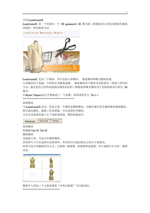
介绍LookStailorXLookStailorX 是一个发展从一个 3D garment.It 2D 模式的三维服装设计系统为图案在服装业提供一种创新的方法..LookStailorX 是由三个模块;其中包括人体模块、服装模块和模式模块组成..人体模块用于创建一个机构负责服装建模、服装模块用于模型为身体使用一种基于草绘的方法;通过更改它的等高线修改服装形状的三维服装和模式模块用于绘制线条设计研发 2D 模式..系统模块当LookStailorX启动;将显示第一个模块是模特模块..对操作顺序是从模特模块服装模块;然后格局模块..根据工作需要做;可以选择任何模块..点击在该系统的窗口左下角标签按钮;模块将被选中..系统模块快捷键Ctrl键/ Tab键模特模块该虚拟人体;可显示在模特模块..类型和尺寸可以选择从身体清单;其形状可以通过指定它的大小值修改..阿体可显示和编辑任何4次:正视图;侧视图;俯视图和透视图;每个视图可分为单一视图改变..数据导入到这三个方面是衡量“纤体扫描器”可以做到的..Garment Module在模特模块创建的身体可以显示在服装模块..使用该函数创建服装;一个正常的或紧身服装可以被创建..服装后生成;它的形状可以通过改变它轮廓线和截面修改..有两个服装模块查看模式:4点意见和单一视图..阿其下属机构和服装可以显示在任何编辑的四点看法:正视图;侧视图;俯视图和透视图;以及每个视图可分为单一视图改变..模式模块与服装模块中创建其下属机构服装可以显示模式模块的 3D 视图..要创建 2D 模式;首先绘制线和省道线;3D 的服装在 2D 模式;然后展开3D 修补程序的设计..如果粮食行设置一个 3D 的修补程序对它展开之前;粮食线将用作扩展的一个基准线..3D 修补程序会显示在 3D 视图和 2D 模式在二维视图中显示..模式模块中有两个视图模式:两个视图和单一视图.. 对于任何两个视图的它可以更改到单个视图中..第1章界面Operation Range维和行动的范围包括下列内容:菜单每个菜单项对应一个指定的操作..工具栏在工具栏上的每个按钮对应一显示或编辑一个机构指定的工具..标签按钮在系统窗口的左下角;3个选项卡按钮对应三个不同的模块:模特;服装和模式..点击任何标签按钮选择一个模块..查看显示当加载一个机构;它会显示在四点看法;如下图所示..顶视图默认情况下显示的腰部剖面..透视在单个视图模式和四个视图模式下的两个视图方向都可以自由更改透视视图..1单击透视视图.. 视图中;选择;其框架的颜色将被更改为黄色..2单击菜单项;以更改视图的方向;或使用下列快捷键更改视图方向..查看方向捷径前视图F中的关键后视图乙键顶视图吨的关键底视图ü关键左侧查看左键右侧视图右键透视图关键渲染模式有两种渲染模式:树荫和线框显示一个机构..要更改渲染模式:按一下按钮渲染模式的工具栏..渲染模式将被改变之间的树荫模式和旋转线框模式按一下按钮..或按一下按钮的渲染模式右侧的小三角按钮;然后将一个下拉菜单选择任何渲染模式显示..灯罩模式:显示一个机构;阴凉处..仸默认渲染模式的阴影..渲染模式菜单查看菜单/渲染模式分割视窗该系统窗口可以显示在两种模式:单视图和四点看法..要显示一个视图:点击以显示..一旦认为被选中;在其框架颜色会改变为黄色..按一下按钮拆分窗口的工具栏;然后视图将改为单一视图..单查看菜单查看/分割视窗/单查看快捷空格键要显示四点看法:按一下按钮拆分窗口的工具栏;然后系统窗口将改为4次四点看法菜单查看/斯普利特的Windows / 4点击快捷空格键截面它是用来显示一个在任何位置身体横截面..按一下看法..一旦选定一个观点是;在其框架颜色会改变为黄色..按Ctrl键;然后离开拖动黄色腰线..绿色的截面将显示在鼠标位置;和一个截面将在顶视图显示中心..可设定断面;除顶视图的所有意见..双击任何胸围;腰围;臀围;下摆特征线;其颜色会改变为黄色..一个截面的位置可以设定输入值..1:按一下看法..一旦选定一个观点是;在其框架颜色会改变为黄色..2:按Ctrl键;然后拖动左横截面为指定位置..3:点击菜单查看->截面..4:设置一个对话框弹出断面位置;然后输入的偏移值..5:按下按钮确定;然后断面将被移动到指定的位置Keyboad为了使用LookStailorX方便;下面的键提供支持的一些工具和系统的命令..移 Ctrl键 ALT键空间删除右箭头左箭头热门箭鼠标左点击点击左键一次..用鼠标点击单击向右按钮..双击点击左边的按钮而无需移动鼠标快速连续两次.. 左拖动移动鼠标;同时保持按下左键.. 用鼠标拖动移动鼠标;同时保持按下正确的按钮.. 左+右拖动移动鼠标;同时保持按下左;右两个按钮..第2章系统设置测量单元它是用来设置测量单位和精度..有3个单位是毫米;厘米和英寸..单击菜单设置->测量装置..测量单元一个对话框弹出;然后设置测量单位和精度..按一下按钮确定所选择的设置单位和精度..弹出一个对话框;确认设置..按一下按钮是;然后设置将应用到所有的模块..按一下按钮没有;然后设置将被取消..网格尺寸它是用来设置背景网格的大小..单击菜单设置->网格尺寸..弹出一个对话框;然后输入了网格大小的值..按一下按钮确定..默认的网格大小为10cm..图中显示的背景网格;工具栏工具栏可以拖动到系统的任何窗口的地方..在工具栏左侧单击并拖动它..工具栏可以放置在任何窗口;或在窗口顶部或底部的固定位置..第三章基本操作撤消和重做...撤消用来恢复过去的编辑操作..该撤消的最大数量是20..复原菜单编辑/撤消快捷键Ctrl键/为Z键重做是要推翻一个撤消操作..重做菜单编辑/重做快捷键Ctrl键/ Y键工具栏显示它是用来设置工具栏的可见或不可见的..要显示一个工具栏:点击菜单查看->工具栏;菜单项将被选中;和工具栏将显示..要隐藏工具栏:点击菜单查看->工具栏;菜单项将被不加制止;和工具栏将被隐藏透视在单一视图模式和4次模式两者;认为方向可以自由改变角度的看法..点击透视图..一旦认为被选中;在其框架颜色会改变为黄色..点击菜单项的改变方向;或使用以下快捷键的改变方向..查看方向捷径前视图F中的关键后视图乙键顶视图吨的关键底视图ü关键左侧查看左键右侧视图右键透视图关键渲染模式有两种渲染模式:树荫和线框显示一个机构..要更改渲染模式:按一下按钮渲染模式的工具栏..渲染模式将被改变之间的树荫模式和旋转线框模式按一下按钮..或按一下按钮的渲染模式右侧的小三角按钮;然后将一个下拉菜单选择任何渲染模式显示..线框模式:显示一个机构代表一个网格..灯罩模式:显示一个机构;树荫默认渲染模式是树荫..渲染模式菜单查看/渲染模式分割视窗该系统窗口可以显示在两种模式:单视图和四点看法..要显示一个视图:点击以显示..一旦认为被选中;在其框架颜色会改变为黄色..按一下按钮在工具栏分割视窗;那么视图将改为单一视图要显示4分裂的看法:按一下按钮拆分窗口的工具栏;然后系统窗口将改为4次..轮流一个机构可以自由地旋转角度的看法..点击透视图..一旦认为被选中;在其框架颜色会改变为黄色..点击工具栏上的按钮旋转.. 左拖动旋转中透视机构..左拖动;同时保持按下键Ctrl + Alt键可以旋转的身体水平..轮流菜单查看/转换/旋转快捷Alt键/左拖动移动一个身体可以移动的所有意见..按一下看法..一旦选定一个观点是;在其框架颜色会改变为黄色..按一下按钮;移动的工具栏..放大一个机构可以在所有视图中进行缩放..要放大:按一下看法..一旦选定一个观点是;和它的框架的颜色会改变为黄色..点击工具栏上的按钮放大..在身体变焦通过移动鼠标由左到右;而左边的按钮被按下..要缩小选择一个视图..一旦认为被选中;其框架的颜色会改变为黄色..点击工具栏上的按钮放大..在体内通过移动鼠标变焦由右至左;而左边的按钮被按下..放大菜单查看/转换/缩放快捷Alt键/左+右拖动鼠标滚轮缩放全部变焦都是用来做全身出现在一个视图..按一下看法..一旦选定一个观点是;在其框架颜色会改变为黄色..点击工具栏按钮中的所有缩放;然后整个身体被显示在当前视图..缩放全部菜单查看/转换/缩放全部快捷键C键截面它是用来显示一个在任何位置身体横截面..按一下看法..一旦选定一个观点是;在其框架颜色会改变为黄色..按下键Ctrl键;然后离开拖动黄色腰线..绿色的截面将显示在鼠标位置和断面将在顶视图显示中心..可设定断面;除顶视图的所有意见..双击任何胸围;腰围;臀围;下摆特征线;其颜色会改变为黄色..一个截面的位置可以设定输入值..按一下看法..一旦选定一个观点是;在其框架颜色会改变为黄色..按下键Ctrl键;然后拖动左横截面为指定位置..点击菜单查看->截面..设置一个对话框弹出断面位置;然后输入的偏移值..按下按钮确定;然后断面将被移动到指定位置..。
VIAVI Solutions IFR6015 软件版本0 4.21.00 说明书

Software Release NotesIFR6015 Software Version 04.21.00 Available9/20/2023DescriptionThe latest released software version for the IFR6015 has changed from Version 4.19.00 to Version 4.21.00. (MKII units only - identified by the presence of MOD Strike 2 on the mod status placard.)New Features•NoneImprovements•Added the indication of a Military Emergency (EM) on the transponder autotest when the reply is followed by three sets of framing pulses spaced appropriately.•Corrected the ability to perform transponder testing while the aircraft is configured for “on the ground” condition.Errata•NoneNote: the installation of this new software does not require the IFR6015 to be recalibrated. Download InstructionsThe installation package can be downloaded here:https:///en-us/software-download/ifr6015-softwareContact InformationVIAVI SolutionsAvionics and Radio Test10200 West York StreetWichita, KS 67215800-835-23509/20/2022DescriptionThe latest released software version for the IFR6015 has changed from Version 04.18.00 to Version 04.19.00. (MKII units only - identified by the presence of MOD Strike 2 on the mod status placard.)ImprovementsTACAN:•Improved UUT DME P1 and P2 pulse width measurement.GENERAL:•Firmware support for a new GPS Receiver component due to obsolescence.IFR6015 Software Version 04.18.00 Available3/18/2021DescriptionThe latest released software version for the IFR6015 has changed from Version 04.15.00 to Version 04.18.00. (MKII units only - identified by the presence of MOD Strike 2 on the mod status placard.)ImprovementsTACAN:•Morse code ident feature was modified to provide proper timing of the morse code ident cycle.XPDR:• A provision for enabling or disabling the Discriminator test is provided in the transponder autotest.IFR6015 Software Version 04.15.00 Available9/29/2019DescriptionThe latest released software version for the IFR6015 has changed from Version 04.13.00 to Version 04.15.00. (MKII units only - identified by the presence of MOD Strike 2 on the mod status placard.)ImprovementsGeneral:•Remote commands :ADSB:CPR:LONG and :ADSB:CPR:LAT was fixed.XPDR:•Fixed an anomaly where on a 'NO REPLY' is returned when the UUT Address is set to Manual Address.TCAS:•UUT ALT was displaying incorrect data for altitudes greater than 32750ft.IFR6015 Software Version 02.13.00 Available8/14/2016DescriptionThe latest released software version for the IFR6015 has changed from Version 02.09.00 to Version 02.13.00. (MKI units only - identified by the presence of MOD Strike 1 and below but not mod strike 2 on the mod status placard.)New FeaturesGeneral:-Added ADSB Integrity option.Improvements-On AC20-165 test, the test status was corrected to display "BAD SETUP" if the MOPS Version is earlier than DO-260B.-Remote command "ADSB:GICB:BD61:ST2:DATA?" was causing the test set to reboot.-Pressing the "BKLT" button in "ADSB-ADSB STORE DATA" screen locked up the unit-Corrected handling of loss when direct port with coupler is selected.-Addressed an issue where a UUT that is set to 'Ground' fails after successfully testing another UUT with a different Mode S address.-When Type Code 0 does not have altitude, the squitter is displayed as a Surface Position squitter until BDS Register 6,5 subtype code is receivedto determine if the UUT is in 'Air' or on 'Ground'.-Addressed an issue where a 'Pass' is displayed in AC 20-165 test when no data is present.DME:-Corrected handling of loss when direct port with coupler is selected.XPDR:-Addressed issue where Mode S All-call and reply ratio fails when the UUT is set to ground. -Corrected tail country code for Argentina-Addressed an issue where a 'PASS' is displayed in XPDR-S REPLY test when a UUT that is set to 'Air' does not have SQTR and DIVERSITY ISOLATION data present.-Fixed truncated tail number for Republic of Korea.XPDR DIAG:-Improved percent reply measurement.-Fixed the reboot issue in XPDR DIAGNOSTICS when the SLS is +3 dB for direct and direct with coupler.ALT ENCODER:General:TCAS:TIS:TACAN: (6015 only)-Corrected handling of loss when direct port with coupler is selecteDownload InstructionsThe latest installation package can be downloaded here:https:///en-us/literature/ifr6015-software-release-notes-software-firmware-releases-en.pdfContact InformationVIAVI SolutionsAvionics and Radio Test10200 West York StreetWichita, KS 67215800-835-2350*************************************。
- 1、下载文档前请自行甄别文档内容的完整性,平台不提供额外的编辑、内容补充、找答案等附加服务。
- 2、"仅部分预览"的文档,不可在线预览部分如存在完整性等问题,可反馈申请退款(可完整预览的文档不适用该条件!)。
- 3、如文档侵犯您的权益,请联系客服反馈,我们会尽快为您处理(人工客服工作时间:9:00-18:30)。
日本L o o k S i l o r D打板软件说明书集团文件发布号:(9816-UATWW-MWUB-WUNN-INNUL-DQQTY-介绍LookStailorXLookStailorX 是一个发展从一个 3D garment.It 2D 模式的三维服装设计系统为图案在服装业提供一种创新的方法。
LookStailorX 是由三个模块,其中包括人体模块、服装模块和模式模块组成。
人体模块用于创建一个机构负责服装建模、服装模块用于模型为身体使用一种基于草绘的方法,通过更改它的等高线修改服装形状的三维服装和模式模块用于绘制线条设计研发 2D 模式。
***************************************系统模块当LookStailorX启动,将显示第一个模块是模特模块。
对操作顺序是从模特模块服装模块,然后格局模块。
根据工作需要做,可以选择任何模块。
点击在该系统的窗口左下角标签按钮,模块将被选中。
系统模块快捷键Ctrl键/ Tab键模特模块该虚拟人体,可显示在模特模块。
类型和尺寸可以选择从身体清单,其形状可以通过指定它的大小值修改。
阿体可显示和编辑任何4次:正视图,侧视图,俯视图和透视图,每个视图可分为单一视图改变。
数据导入到这三个方面是衡量“纤体扫描器”可以做到的。
****************************Garment Module在模特模块创建的身体可以显示在服装模块。
使用该函数创建服装,一个正常的或紧身服装可以被创建。
服装后生成,它的形状可以通过改变它轮廓线和截面修改。
有两个服装模块查看模式:4点意见和单一视图。
阿其下属机构和服装可以显示在任何编辑的四点看法:正视图,侧视图,俯视图和透视图,以及每个视图可分为单一视图改变。
*******************模式模块与服装模块中创建其下属机构服装可以显示模式模块的 3D 视图。
要创建 2D 模式,首先绘制线和省道线,3D 的服装在 2D 模式,然后展开 3D 修补程序的设计。
如果粮食行设置一个 3D 的修补程序对它展开之前,粮食线将用作扩展的一个基准线。
3D 修补程序会显示在 3D 视图和 2D 模式在二维视图中显示。
模式模块中有两个视图模式:两个视图和单一视图。
对于任何两个视图的它可以更改到单个视图中。
第1章界面Operation Range维和行动的范围包括下列内容:菜单每个菜单项对应一个指定的操作。
工具栏在工具栏上的每个按钮对应一显示或编辑一个机构指定的工具。
标签按钮在系统窗口的左下角,3个选项卡按钮对应三个不同的模块:模特,服装和模式。
点击任何标签按钮选择一个模块。
查看显示当加载一个机构,它会显示在四点看法,如下图所示。
顶视图默认情况下显示的腰部剖面。
透视在单个视图模式和四个视图模式下的两个视图方向都可以自由更改透视视图。
1单击透视视图。
视图中,选择,其框架的颜色将被更改为黄色。
2单击菜单项,以更改视图的方向,或使用下列快捷键更改视图方向。
查看方向捷径前视图[F]中的关键后视图[乙]键顶视图[吨]的关键底视图[ü]关键左侧查看[左]键右侧视图[右]键透视[图]关键渲染模式有两种渲染模式:树荫和线框显示一个机构。
要更改渲染模式:按一下按钮渲染模式的工具栏。
渲染模式将被改变之间的树荫模式和旋转线框模式按一下按钮。
或按一下按钮的渲染模式右侧的小三角按钮,然后将一个下拉菜单选择任何渲染模式显示。
灯罩模式:显示一个机构,阴凉处。
仸默认渲染模式的阴影。
渲染模式菜单查看菜单/渲染模式分割视窗该系统窗口可以显示在两种模式:单视图和四点看法。
要显示一个视图:点击以显示。
一旦认为被选中,在其框架颜色会改变为黄色。
按一下按钮拆分窗口的工具栏,然后视图将改为单一视图。
单查看菜单查看/分割视窗/单查看快捷空格键要显示四点看法:按一下按钮拆分窗口的工具栏,然后系统窗口将改为4次四点看法菜单查看/斯普利特的Windows / 4点击快捷空格键截面它是用来显示一个在任何位置身体横截面。
按一下看法。
一旦选定一个观点是,在其框架颜色会改变为黄色。
按Ctrl键,然后离开拖动黄色腰线。
绿色的截面将显示在鼠标位置,和一个截面将在顶视图显示中心。
*可设定断面,除顶视图的所有意见。
*双击任何胸围,腰围,臀围,下摆特征线,其颜色会改变为黄色。
一个截面的位置可以设定输入值。
1:按一下看法。
一旦选定一个观点是,在其框架颜色会改变为黄色。
2:按Ctrl键,然后拖动左横截面为指定位置。
3:点击菜单查看->截面。
4:设置一个对话框弹出断面位置,然后输入的偏移值。
5:按下按钮确定,然后断面将被移动到指定的位置Keyboad为了使用LookStailorX方便,下面的键提供支持的一些工具和系统的命令。
移 Ctrl键 ALT键空间删除右箭头左箭头热门箭鼠标左点击点击左键一次。
用鼠标点击单击向右按钮。
双击点击左边的按钮而无需移动鼠标快速连续两次。
左拖动移动鼠标,同时保持按下左键。
用鼠标拖动移动鼠标,同时保持按下正确的按钮。
左+右拖动移动鼠标,同时保持按下左,右两个按钮。
第2章系统设置测量单元它是用来设置测量单位和精度。
有3个单位是毫米,厘米和英寸。
单击菜单设置->测量装置。
测量单元一个对话框弹出,然后设置测量单位和精度。
按一下按钮确定所选择的设置单位和精度。
弹出一个对话框,确认设置。
按一下按钮是,然后设置将应用到所有的模块。
按一下按钮没有,然后设置将被取消。
网格尺寸它是用来设置背景网格的大小。
单击菜单设置->网格尺寸。
弹出一个对话框,然后输入了网格大小的值。
按一下按钮确定。
默认的网格大小为10cm。
图中显示的背景网格;工具栏工具栏可以拖动到系统的任何窗口的地方。
在工具栏左侧单击并拖动它。
工具栏可以放置在任何窗口,或在窗口顶部或底部的固定位置。
第三章基本操作撤消和重做...撤消用来恢复过去的编辑操作。
*该撤消的最大数量是20。
复原菜单编辑/撤消快捷键Ctrl键/为[Z]键重做是要推翻一个撤消操作。
重做菜单编辑/重做快捷键Ctrl键/ [Y]键工具栏显示它是用来设置工具栏的可见或不可见的。
要显示一个工具栏:点击菜单查看->工具栏,菜单项将被选中,和工具栏将显示。
要隐藏工具栏:点击菜单查看->工具栏,菜单项将被不加制止,和工具栏将被隐藏透视在单一视图模式和4次模式两者,认为方向可以自由改变角度的看法。
点击透视图。
一旦认为被选中,在其框架颜色会改变为黄色。
点击菜单项的改变方向,或使用以下快捷键的改变方向。
查看方向捷径前视图[F]中的关键后视图[乙]键顶视图[吨]的关键底视图[ü]关键左侧查看[左]键右侧视图[右]键透视[图]关键渲染模式有两种渲染模式:树荫和线框显示一个机构。
要更改渲染模式:按一下按钮渲染模式的工具栏。
渲染模式将被改变之间的树荫模式和旋转线框模式按一下按钮。
或按一下按钮的渲染模式右侧的小三角按钮,然后将一个下拉菜单选择任何渲染模式显示。
线框模式:显示一个机构代表一个网格。
灯罩模式:显示一个机构,树荫默认渲染模式是树荫。
渲染模式菜单查看/渲染模式分割视窗该系统窗口可以显示在两种模式:单视图和四点看法。
要显示一个视图:点击以显示。
一旦认为被选中,在其框架颜色会改变为黄色。
按一下按钮在工具栏分割视窗,那么视图将改为单一视图要显示4分裂的看法:按一下按钮拆分窗口的工具栏,然后系统窗口将改为4次。
轮流一个机构可以自由地旋转角度的看法。
点击透视图。
一旦认为被选中,在其框架颜色会改变为黄色。
点击工具栏上的按钮旋转。
左拖动旋转中透视机构。
*左拖动,同时保持按下键Ctrl + Alt键可以旋转的身体水平。
轮流菜单查看/转换/旋转快捷Alt键/左拖动移动一个身体可以移动的所有意见。
按一下看法。
一旦选定一个观点是,在其框架颜色会改变为黄色。
按一下按钮,移动的工具栏。
放大一个机构可以在所有视图中进行缩放。
要放大:按一下看法。
一旦选定一个观点是,和它的框架的颜色会改变为黄色。
点击工具栏上的按钮放大。
在身体变焦通过移动鼠标由左到右,而左边的按钮被按下。
要缩小选择一个视图。
一旦认为被选中,其框架的颜色会改变为黄色。
点击工具栏上的按钮放大。
在体内通过移动鼠标变焦由右至左,而左边的按钮被按下。
放大菜单查看/转换/缩放快捷Alt键/(左+右)拖动鼠标滚轮缩放全部变焦都是用来做全身出现在一个视图。
按一下看法。
一旦选定一个观点是,在其框架颜色会改变为黄色。
点击工具栏按钮中的所有缩放,然后整个身体被显示在当前视图。
缩放全部菜单查看/转换/缩放全部快捷键[C]键截面它是用来显示一个在任何位置身体横截面。
按一下看法。
一旦选定一个观点是,在其框架颜色会改变为黄色。
按下键Ctrl键,然后离开拖动黄色腰线。
绿色的截面将显示在鼠标位置和断面将在顶视图显示中心。
*可设定断面,除顶视图的所有意见。
*双击任何胸围,腰围,臀围,下摆特征线,其颜色会改变为黄色。
一个截面的位置可以设定输入值。
按一下看法。
一旦选定一个观点是,在其框架颜色会改变为黄色。
按下键Ctrl键,然后拖动左横截面为指定位置。
点击菜单查看->截面。
设置一个对话框弹出断面位置,然后输入的偏移值。
按下按钮确定,然后断面将被移动到指定位置。