NSC890电网解列说明书
解列装置说明书
0XJ 463 292第 2 页共 38 页旧底图总号底图总号签字日期3.3.3零序过压解列 (15)3.3.4TV异常检测 (15)3.4装置故障告警 (16)3.5测控功能 (16)3.6辅助功能 (16)3.6.1录波 (16)3.6.2GPS对时 (17)3.6.3打印功能 (17)3.6.4网络通信 (17)4装置使用说明 (17)4.1定值整定信息 (17)4.1.1定值表 (17)4.1.2保护定值 (18)4.1.3软压板 (19)4.1.4硬压板 (19)4.2动作信息及说明 (19)4.3人机界面说明 (19)4.3.1面板说明 (19)4.3.2按键与显示屏 (20)4.3.3指示灯 (20)4.3.4显示说明 (20)4.3.5菜单结构 (21)4.3.6浏览菜单 (22)4.3.7整定菜单 (24)4.3.8打印菜单 (28)4.3.9调试菜单 (29)4.3.10版本 (30)4.3.11自动信息显示 (30)5调试及异常处理 (31)5.1调试说明 (31)5.2程序检查 (31)5.3开关量输入检查 (31)5.4继电器开出回路检查 (31)5.5模拟量输入检查 (32)5.6相位检查 (32)5.7整组试验 (32)5.8异常处理 (32)6投运说明及注意事项 (32)7通信说明 (33)7.1保护动作信号 (33)7.2告警信号 (33)7.3状态信号 (34)7.4控制 (34)7.5总召唤信息 (35)8贮存及保修 (35)0XJ 463 292第 3 页共 38 页旧底图总号底图总号签字日期8.1贮存条件 (35)8.2保修时间 (35)9供应成套性 (35)9.1随同产品一起供应的文件 (35)9.2随同产品一起供应的附件 (35)10订货须知 (35)11附图 (36)11.1装置接线示意图 (36)11.1.1P型机箱通信接线说明 (36)11.1.2装置接线示意图 (38)0XJ 463 292第 4 页共 38 页旧底图总号底图总号签字日期1技术指标1.1额定数据a. 额定电源电压: DC220V或DC110V (订货注明)b. 额定交流数据:交流电压:相电压100/3V,线路抽取电压100/3V 或100V。
MAX890L 智能低压 P-通道 MOSFET 电源开关说明书

General DescriptionThe MAX890L smart, low-voltage, P-channel, MOSF ET power switch is intended for high-side load-switching applications. This switch operates with inputs from +2.7V to +5.5V, making it ideal for both +3V and +5V systems. Internal current-limiting circuitry protects the input supply against overload. Thermal-overload pro-tection limits power dissipation and junction tempera-tures.The MAX890L’s maximum current limit is 1.2A. The cur-rent limit through the switch is programmed with a resistor from SET to ground. The quiescent supply cur-rent is a low 10µA. When the switch is off, the supply current decreases to 0.1µA.The MAX890L is available in an 8-pin SO package.ApplicationsPCMCIA Slots Access Bus Slots Portable EquipmentFeatures♦+2.7V to +5.5V Input Range ♦Programmable Current Limit ♦Low Quiescent Current10µA (typ) at V IN = +3.3V 0.1µA (typ) with Switch Off ♦Thermal Shutdown ♦FAULT Indicator Output ♦0.09Ω(typ) On-ResistanceMAX890L1.2A, Current-Limited, High-SideP-Channel Switch with Thermal Shutdown________________________________________________________________Maxim Integrated Products 1Pin ConfigurationTypical Operating Circuit 19-1146; Rev 4; 4/11*To order this unit in tape and reel, add (T) to the end of thepart number.**Dice are tested at T A = +25°C.+Denotes a lead(Pb)-free/RoHS-compliant package./V denotes an automotive qualified part.For pricing, delivery, and ordering information,please contact Maxim Direct at 1-888-629-4642,or visit Maxim’s website at .M A X 890L1.2A, Current-Limited, High-SideP-Channel Switch with Thermal Shutdown 2_______________________________________________________________________________________ABSOLUTE MAXIMUM RATINGSELECTRICAL CHARACTERISTICS(V IN = +3V,T A = 0°C to +85°C,unless otherwise noted. Typical values are at T A = +25°C.)Stresses beyond those listed under “Absolute Maximum Ratings” may cause permanent damage to the device. These are stress ratings only, and functional operation of the device at these or any other conditions beyond those indicated in the operational sections of the specifications is not implied. Exposure to absolute maximum rating conditions for extended periods may affect device reliability.IN to GND ................................................................-0.3V to +6V ON , FAULT to GND .................................................-0.3V to +6V SET, OUT to GND ......................................-0.3V to (V IN + 0.3V)Maximum Continuous Switch Current ..................................1.5A Continuous Power Dissipation (T A = +70°C)SO (derate 5.88mW/°C above +70°C) ..........................471mWOperating Temperature RangeMAX890LESA ....................................................-40°C to +85°C Storage Temperature Range ...........................-65°C to +150°C Lead Temperature (soldering, 10s) ................................+300°C Soldering Temperature (reflow).......................................+260°CMAX890L1.2A, Current-Limited, High-SideP-Channel Switch with Thermal Shutdown_______________________________________________________________________________________3Note 1:Tested with I OUT = 100mA and V SET raised until V IN - V OUT ≥0.8V.Note 2:Specifications to -40°C are guaranteed by design; not production tested.ELECTRICAL CHARACTERISTICS(V IN = +3V, T A = -40°C to +85°C,unless otherwise noted.) (Note 2)M A X 890L1.2A, Current-Limited, High-SideP-Channel Switch with Thermal Shutdown 4_______________________________________________________________________________________OFF-SWITCH CURRENT vs. TEMPERATUREO F F -S W I T C H C U R R E N T (n A)10000.011100.1100NORMALIZED ON-RESISTANCEvs. TEMPERATUREI OUT /I SET RATIO vs. I LIMIT00.20.40.60.81.01.2OUTPUT VOLTAGE (V)N O R M A L I Z E D O U T P U T C U R R E N T123456TEMPERATURE (°C)-40-20402010006080TEMPERATURE (°C)-40-2040201006080__________________________________________Typical Operating Characteristics(T A = +25°C, unless otherwise noted.)024********QUIESCENT CURRENT vs. INPUT VOLTAGEINPUT VOLTAGE (V)0123456Q U I E S C E N T C U R R E N T (μA )7-40-204020100QUIESCENT CURRENT vs. TEMPERATURE9TEMPERATURE (°C)Q U I E S C E N T C U R R E N T (μA )06080131181412101000.01-40-2020604080100OFF-SUPPLY CURRENT vs. TEMPERATURE0.1M A X 890 t o c 03TEMPERATURE (°C)O F F -S U P P L Y C U R R E N T (n A )110V IN = 5V A: I OUT = 0mA TO 750mA, 0.5A/divLOAD-TRANSIENT RESPONSEA B0A0V 5ms/divB: V OUT RIPPLE, 200mV/div, AC COUPLED MAX890 toc12V IN = 5V, I OUT = I LIMIT A: V ON , 2V/div B: V OUT , 2V/divSWITCH TURN-ON TIMEAB20μs/divMAX890 toc13C IN = 100μF, C OUT = 0.1μF A: V IN , 1V/div, AC-COUPLEDOUTPUT SHORT-CIRCUIT (FAST LOOP RESPONSE)A 5VBC 0V2μs/div0AB: I OUT , 5A/div C: V OUT , 2V/divMAX890 toc11C IN = 100μF, C OUT = 0.1μF A: V IN , 1V/div, AC-COUPLEDOUTPUT OVERLOAD (SLOW LOOP RESPONSE)A 5VBC 0V, 0A2μs/divB: I OUT , 1A/div C: V OUT , 2V/divMAX890 toc10MAX890L1.2A, Current-Limited, High-SideP-Channel Switch with Thermal Shutdown_______________________________________________________________________________________5____________________________Typical Operating Characteristics (continued)(T A = +25°C, unless otherwise noted.)SWITCH TURN-OFF TIMEAB0V0V2μs/divV IN = 5V, I OUT = I LIMIT A: V ON , 2V/div B: V OUT , 2V/divMAX890 toc14M A X 890L1.2A, Current-Limited, High-SideP-Channel Switch with Thermal Shutdown 6_______________________________________________________________________________________Pin DescriptionSwitch Output. P-channel MOSFET drain. Bypass OUT with a 0.1μF capacitor to ground.OUT 6, 7Fault-Indicator Output. This open-drain output goes low when in current limit or when the die temperature exceeds +135°C.FAULT8Set Current-Limit Input. A resistor from SET to ground sets the current limit for the switch. R SET = 1.38 x 10³/I LIMIT,where I LIMIT is the desired current limit in amperes.SET 5GroundGND 4PIN Active-Low Switch On Input. A logic low turns the switch on.ON 3Input. P-channel MOSFET source. Bypass IN with a 1μF capacitor to ground.IN 1, 2FUNCTIONNAME Detailed DescriptionThe MAX890L P-channel MOSF ET power switch limits output current to a programmed level. When the output current is increased beyond the programmed current limit, or 1.2A (I MAX ), the current also increases through the replica switch (I OUT /1110) and through R SET (F igure 1). The current-limit error amplifier compares the voltage across R SET to the internal +1.24V refer-ence and regulates the current back to the lesser of the programmed limit (I LIMIT ) or 1.2A.This switch is not bidirectional; therefore, the input volt-age must be higher than the output voltage.Setting the Current LimitThe MAX890L features internal current-limiting circuitry with a maximum programmable value (I MAX ) of 1.2A.F or best performance, set the current limit (I LIMIT )between 0.2 I MAX ≤I LIMIT ≤I MAX . This current limit remains in effect throughout the input supply-voltage range.Program the current limit with a resistor (R SET ) from SET to ground (Figure 2) as follows:I SET = I LIMIT / 1110R SET = 1.24V / I 8 = 1.38 x 10³/ I LIMITwhere I LIMIT is the desired current limit.Short-Circuit ProtectionThe MAX890L is a short-circuit-protected switch. In the event of an output short circuit or current-overload con-dition, the current through the switch is limited by the internal current-limiting error amplifier to 1.5 x I LIMIT .When the fault condition is removed, the replica error amplifier sets the current limit back to I LIMIT .F or a high dV DS /dt during an output short-circuit condi-tion, the switch turns off and disconnects the input supply from the output. The current-limiting amplifier then slow-ly turns the switch on with the output current limited to 1.5 x I LIMIT . When the fault condition is removed, the current limit is set back to I LIMIT . Refer to the Output Short-Circuit Fast-Loop Response and Output Overload Slow-Loop Response in the Typical Operating Characteristics .Figure 1. Functional DiagramMAX890L1.2A, Current-Limited, High-SideP-Channel Switch with Thermal Shutdown_______________________________________________________________________________________7Thermal ShutdownThe MAX890L features thermal shutdown. The switch turns off when the junction temperature exceeds +135°C. Once the device cools by 10°C, the switch turns back on. If the fault short-circuit condition is not removed, the switch cycles on and off, resulting in a pulsed output.Fault IndicatorThe MAX890L provides a fault output (FAULT ). This open-drain output goes low when in current limit or when the die temperature exceeds +135°C. A 100k Ωpull-up resistor from FAULT to IN provides a logic-control signal.Applications InformationInput CapacitorTo limit the input voltage drop during momentary output short-circuit conditions, connect a capacitor from IN to GND. A 1µF ceramic capacitor is adequate for mostapplications; however, higher capacitor values further reduce the voltage drop at the input.Output CapacitorConnect a 0.1µF capacitor from OUT to GND. One function of this capacitor is to prevent inductive para-sitics from pulling OUT negative during turn-off.Layout and Thermal-DissipationConsiderationTo take full advantage of the switch-response time to output short-circuit conditions, it is very important to keep all traces as short as possible to reduce the effect of undesirable parasitic inductance. Place input and output capacitors as close as possible to the device (no more than 5mm).Under normal operating conditions, the package can dissipate and channel heat away. Calculate the maxi-mum power as follows:P = I 2LIMIT x R ON where R ON is the on-resistance of the switch.When the output is short circuited, the voltage drop across the switch equals the input supply. Hence, the power dissipated across the switch increases, as does the die temperature. If the fault condition is not removed, the thermal-overload-protection circuitry turns the switch off until the die temperature falls by 10°C. A ground plane in contact with the device helps dissipate additional heat.Package InformationF or the latest package outline information and land patterns (footprints), go to /packages . Note that a “+”, “#”, or “-” in the package code indicates RoHS status only.Package drawings may show a different suffix character, but the drawing pertains to the package regardless of RoHS status.Figure 2. Setting the Current LimitM A X 890L1.2A, Current-Limited, High-SideP-Channel Switch with Thermal Shutdown Maxim cannot assume responsibility for use of any circuitry other than circuitry entirely embodied in a Maxim product. No circuit patent licenses are implied. Maxim reserves the right to change the circuitry and specifications without notice at any time.8_____________________Maxim Integrated Products, 120 San Gabriel Drive, Sunnyvale, CA 94086 408-737-7600©2011 Maxim Integrated ProductsMaxim is a registered trademark of Maxim Integrated Products, Inc.。
NS+901线路保护测控装置说明书

4.2 保护参数
4.2.1 电流元件 动作电流 : 级差: 误差 :
此外该模件还包括八路遥信量回路,为提高遥信回路的抗干扰能力,遥信采用强电输入 (220V 或 110V),完善、周到的设计可防止直流接地引起的遥信状态变位。
NS 901 线路保护测控装置 说明书
南京电力自动化设备总厂 南京南自科技发展有限公司
第一部分 技术说明书
目录
1 装置概述…………………………………………………………………………………………1 2 装置特点……………………………………………………………………………………………1 3 主要功能……………………………………………………………………………………………2
5.3 CPU 模件
CPU 模件是装置的核心部分,模件内包括两个独立的 CPU,分别完成人机界面管理和保护测 控功能。其中保护测控功能是以高速 DSP 芯片为核心,配合高速存储器、大规模逻辑电路和高 精度采样芯片,保证了装置的可靠性和先进性。插件采用多层印制板及表面贴装工艺,提高了 装置的稳定性及抗电磁干扰能力。
4控制型定值一览表序号定值名称整定范围1电流段保护投入退出2电流段电压闭锁投入退出3电流段方向闭锁投入退出4电流段保护投入退出5电流段电压闭锁投入退出6电流段方向闭锁投入退出7电流段保护投入退出8电流段电压闭锁投入退出9电流段方向闭锁投入退出10电流反时限保护投入退出11电流反时限特性一般非常极端12电流反时限电压闭锁投入退出13电流反时限方向闭锁投入退出14电流加速保护投入退出15pt断线检查投入退出16pt断线闭锁过流投入退出17零序段保护投入退出18零序段方向闭锁投入退出19零序段保护投入退出20零序段方向闭锁投入退出21零序段保护投入退出22零序段方向闭锁投入退出23零序反时限保护投入退出24零序反时限特性一般非常极端25零序反时限方向闭锁投入退出26零序加速保护投入退出27小电流接地零序投入退出28小电流零序投信投跳投信投跳29过负荷保护投入退出?事件信息一览表?1030过负荷保护投信投跳投信投跳31低频减载投入退出32低频减载滑差闭锁投入退出33低频减载低压闭锁投入退出34低频减载电流闭锁投入退出35低压解列投入退出36重合闸投入退出37重合闸方式非同期检同期检无压38加速方式前加速后加速39控制回路断线投入退出40pt接线形式星形三角41电度表投入退出42液晶自动关投入退出3
NSC891S低频低压解列技术说明书..
NSC 891S数字式低频低压解列装置技术说明书国电南京电力自动化设备总厂2005年6月* 本公司保留对此说明书修改的权利,请注意最新版本资料目次2技术参数 (3)2.1额定参数 (3)2.2主要技术性能 (4)2.3绝缘性能 (4)2.4电磁兼容性能 (5)2.5机械性能 (5)2.6环境条件 (6)4 保护原理 (12)4.5TV断线检测 (13)4.6数据记录 (13)5 定值及整定说明 (14)5.1NSC891S数字式低频低压保护装置整定值清单: (14)5.2NSC891S数字式低频低压保护装置装置软压板清单: (15)1 装置简介本保护装置基本配置为两个CPU插件,由32位微处理器构成的保护及控制单元,该单元配置了大容量的RAM和Flash Memory,具有极强的数据处理、逻辑运算和信息存储能力;另一CPU由总线不出芯片的单片机构成通用的人机接口单元。
两个CPU插件之间相互独立,无依存关系。
各种保护功能及自动化功能均由软件实现。
1)装置特点1:全中文汉化液晶显示,人机界面友善,操作方面。
2:专用测量模块,包括电度计量在内的各种测量及计量精度可达0.5级3:提供累计脉冲电度的接入端4:配置了充足的开关量输入端,方便外部遥信量的接入5:装置自带操作回路及就地操作把手,不需附加其它设备即可直接跳合开关6:设置了高精度的时钟芯片,并配置有GPS硬件对时回路,便于全系统时钟同步7:配备高速以太网络通信接口,并集成了IEC 60870-5-103标准通信规约8:完善的故障录波功能2)完备的保护功能配置表1 本系列产品的型号及功能配置表功能NSC 891S功能NSC 891S低周减载保护√过频保护√低压保护√过压保护√遥信√GPS对时√防误闭锁√远方管理√3)监控功能1:遥信:16路遥信开入量的采集、装置遥信变位、事件遥信等2:遥脉:2路电度脉冲输入3:开出:装置具有13路开出,其中10路由于驱动出口跳闸继电器,3路用于预告警信号驱动。
VC890D型万用表的使用

11
VC890D数字型万用表的使用方法
万
测量火线和人体之间电压是123V
用
表
找
火
火线、地线判断及正确接法
线
和
1. 用红表笔接火线口,用
测
左手捏着黑表笔表针测量有
量
100V以上电压证明火线正常;
设
备
2. 另外可以左手捏着黑表
漏
笔,用红表笔依次接左右插座 口找火线(有些网点加装的电
电
源没按规定接,火线和零线接
精选版课件ppt
3
VC890D数字型万用表的使用方法
三、使用注意事项
1. 如果无法预先估计被测电压或电流的大小,则 应先拨至最高量程挡测量一次,再视情况逐渐把量程 减小到合适位置。测量完毕,应将量程开关拨到最高 电压挡,并关闭电源。
2. 满量程时,仪表仅在最高位显示数字“1”, 其它位均消失,这时应选择更高的量程。
精选版课件ppt
8
VC890D数字型万用表的使用方法
例二:如何判断设备是否漏电?
1. 将换挡旋钮量程开关箭头指向“V~ 750V”,用左手捏紧黑表笔表针,红表笔表针接 到设备外壳上,如果万用表显示5V以下为正常, 高于5V说明设备外壳带电(漏电)。
2. 可以直接用试电笔测量外壳电压,有5V以 上电压就不正常。
精选版课件ppt
15
VC890D数字型万用表的使用方法
B. 如何判断日常用电线路?
1. 将量程开关箭头指向“V~ 750V”,插表 笔到被测量端“N”零线和”L”火线,正常情况 下显示220左右;
2. 插线板左边孔“N”是零线,中间靠上是 地线孔,右边是“L”火线孔;正常情况下测量火 线和地线电压220V左右,火线和零线电压220V左 右,地线和零线电压低于5V
DPR300S系列数字式电网解列装置说明书10

DPR300S系列数字式电网解列装置
说明书
南京弘毅电气自动化有限公司
* 2008年06月第一次印刷。
* 本说明书内容如有修改,恕不另行通知。
目录
1 概述 (1)
1.1产品适用范围 (1)
1.2产品特点 (1)
2技术参数 (3)
2.1机械及环境参数 (3)
2.2额定电气参数 (3)
2.3电磁兼容 (3)
3 原理说明 (4)
3.1失步振荡解列 (4)
3.2低频控制 (7)
3.3低压控制 (8)
3.4过频控制 (9)
3.5过压控制 (10)
3.6方向过功率或过负荷解列 (10)
4 装置整体说明 (12)
4.1机械结构 (12)
4.2装置主要模块说明 (14)
4.3装置接线图 (16)
5 装置定值表 (18)
5.1DPR301S数字式电网解列装置定值表 (18)
5.2DPR302S数字式频率电压紧急控制装置定值表 (22)
6 装置使用说明 (27)
6.1按键功能说明 (27)
6.2面板布置说明 (27)
6.3命令菜单使用说明 (28)。
oz890 数据手册 编程使用说明介绍
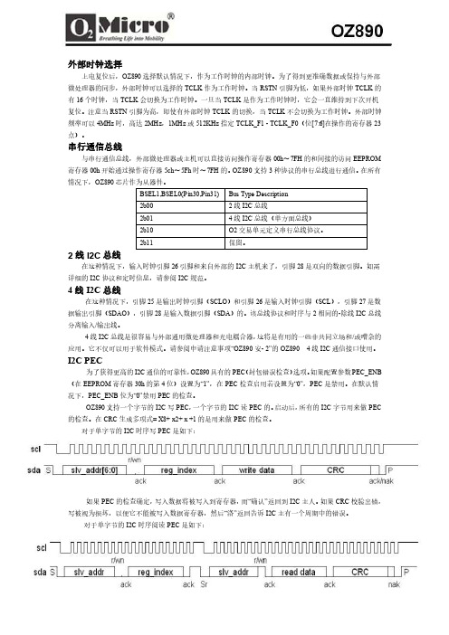
外部时钟选择上电复位后,OZ890选择默认情况下,作为工作时钟的内部时钟。
为了得到更准确数据或保持与外部微处理器的同步,外部时钟可以选择的TCLK作为工作时钟。
当RSTN引脚为低,如果外部时钟TCLK的有16个时钟,当TCLK会切换为工作时钟。
一旦当TCLK是作为工作时钟时,它会一直维持到下次开机复位。
注意当RSTN引脚为高,即使有外部时钟TCLK的切换,当TCLK不会切换为工作时钟。
外部时钟频率可以4MHz时,高达2MHz,1MHz或512KHz指定TCLK_F1 - TCLK_F0(位[7:6]在操作的寄存器23点)。
串行通信总线与串行通信总线,外部微处理器或主机可以直接访问操作寄存器00h〜7FH的和间接的访问EEPROM 寄存器00h开始通过操作寄存器5ch〜5Fh时〜7FH的。
OZ890支持3种协议的串行总线进行通信。
在所有情况下,OZ890芯片作为从器件。
2线I2C总线在这种情况下,输入时钟引脚26引脚和来自外部的I2C主机来了,引脚28是双向的数据引脚。
如需详细的I2C协议和定时信息,请参阅I2C规范。
4线I2C总线在这种情况下,引脚25是输出时钟引脚(SCLO)和引脚26是输入时钟引脚(SCL),引脚27是数据输出引脚(SDAO),引脚28是输入数据引脚(SDA)的。
该总线协议和时序与2相同的-除线I2C总线分离输入/输出线。
4线I2C总线是很容易与外部通用微处理器和光电耦合器,这将是有用的一些非共同立场和/或嘈杂的应用。
它不仅可以用于软件模式。
请参阅申请注意事项“OZ890安- 2”的OZ890 4线I2C通信接口使用。
I2C PEC为了获得更高的I2C通信的可靠性,OZ890具有的PEC(封包错误检查)选项。
如果配置参数PEC_ENB (在EEPROM寄存器30h的第4位)设置为“1”,在PEC检查启用若设置为“0”,PEC是禁用。
在默认情况下,PEC_ENB位为“0”禁用PEC的检查。
数字化电能表表光纤接口使用说明书样本
1 概述DTSD341/DSSD331(配置号为ME2(SN))三相电子式多功效电能表是一款符合DL/T 614《多功效电能表》标准0.2S 级和0.5S 级三相电子式多功效电能表。
其关键特点为计量信号为数字流输入、高速数据处理能力、电源采取双路外接电源供电。
适适用于采取IEC61850-9-1/2标准协议电能计量体系。
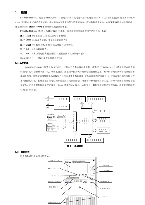
DTSD341/DSSD331(配置号为ME2(SN))三相电子式多功效电能表研发和生产符合以下标准: GB/T 15543《电能质量 三相电压许可不平衡度》 GB/T 17882《2级和3级静止式交流无功电能表》 GB/T 17883《0.2S 级和0.5S 级静止式交流有功电能表》 DL/T 614 《多功效电能表》DL/T 645 《多功效电能表通信规约》(威胜企业对此协议有扩展) IEC61850-9-2 《数字化变电站通信规约》 1.1 工作原理DSSD331/DTSD341(配置号为ME2(SN))三相电子式多功效电能表是一款遵照IEC61850-9-2LE (数字化变电站内通信规约)协议全新数字接口式多功效电能表,采取当今世界流行高级电能表设计方案:数字信号处理器和中央微处理器相结合构架,将数字信号处理器高速数据吞吐能力和中央微处理器 复杂管理能力完美结合。
经过协议处理芯片获取合并单元数据协议包,传送至数字信号处理单元完成对电参量测量,电能累计和电能计算等任务,后和中央微处理器进行数据交换,由中央微处理器最终完成表计显示,数据统计,储存,人机交互,数据交换等复杂管理功效。
其整表硬件原理框图图1所表示。
工工工工-1 工工工工-2工工工工工工10/100MBase-TX(RJ45)100M Base-FX(MIC/1300nm 工工工工工工工工工工工工工工工工工工工工 工工工工/工工工工工工工工工工工 工工工工工工工工工工工工RS485/工工工工工工工工工工2工工工工工工工L1N1L2N2图 1 原理框图1.2 面板说明电表面板说明详见图2所表示。
UT890C+ D真实RMS数字多功能手动测量器操作手册说明书

Range 600mV 0.1mV 0.001V 0.01V 0.1V 1V6V 60V 600V 1000VResolution Accuracy ±(0.5%+4)±(0.5%+2)±(0.7%+10)Range 600Ω0.1Ω0.001kΩ0.01k Ω0.1k Ω0.001MΩ0.01M Ω6k Ω60k Ω600k Ω6M Ω60M ΩResolution Accuracy ±(0.8%+5)±(0.8%+3)±(1.0%+25)Operating ManualI. General IntroductionThis brand new UT890C+/D Operating Manual is a handheld 3-5/6 digit True RMS Digital Multi-meter featuring stable performance and high reliability. Its whole circuit design utilizes a large scale integrated circuit that uses ∑△ADC converter as its core and is further equipped with full function overload protection, making it an ideal tool for users to measure the followings: DC and AC voltage, electric current, resistance, capacitance, frequency, temperature (UT890D/C+), diode, triode and continuity test.Safety Rules and Instructions● This unit is designed and produced in strict accordance with GB4793, Safety Requirements for Electronic Measuring Instrument and Safety Standards coded as IEC61010-1 and IEC1010-2-032. It complies with safe standards, such as double insulation, over voltage (CAT II 1000V, CAT III 600V) and class of pollution II. Please follow the instructions contained in this manual, otherwise the protection provided by this unit may be impaired.● You should not use this unit unless its back cover is properly secured in place, otherwise you are exposed to shock hazard. ● The range switch should be switched to a correct range.● Check the insulation layer of the test leads to ensure no damaged or broken cable.● The red and black test leads should be well inserted into the jacks that are in compliance with the measurement requirements to ensure good contact.● The input signal should not exceed the specified limit value to avoid shock or unit damage.● It is prohibited to change range when measuring voltage or electric current so as to avoid unit damage.● Damaged fuse must only be replaced with fuse with identical specification.● To avoid electric shock, the potential difference measured between “COM” and earth “ ” should be no more than 1000V. ● To avoid electric shock, test with great caution in case the voltage to be measured maybe higher than DV 60V or AC 30Vrms. ● Battery should be replaced in time so as to ensure measurement accuracy when the LCD displays “ ”.● Power should be turned off immediately upon the test is completed and battery should be taken out if it may not be used for a long period of time.● Do not use the unit under an environment with high temperature and high humidity, especially not store it in a wet place as the dampened unit may perform badly.● Please do not change the circuit of the unit arbitrarily so as to avoid unit damage or safety hazard.● Maintenance: Please use wet cloth and mild detergent rather than abrasive material or solvent for the cleaning of its exterior housing.III. Characteristics● More than 30 functional ranges are available.● LCD display, visible area 63×29mm.● Over range display “OL”.● Maximum displayed value 5999.● Overload protection for all ranges.● Auto power off.● Temperature scope:Working temperature: 0℃~40℃(32℉~104℉) Storage temperature: -10℃~50℃(14℉~122℉)● Low battery indicator: The symbol “ ” will be displayed at top left of the LCD.● It has functions, including data hold, measurement of maximum/ minimum value, relative measurement, backlight, etc.II. Symbol DescriptionIV. Technical IndexesAccuracy: ±(α% reading plus figure), 1 year warranty period Environment Temperature: 23℃±5℃ Relative humidity:<75%1. DC VoltageInput impedance: 1GΩfor the range of 600mV while 10MΩ for all2. AC VoltageRange 6V 0.001V 0.01V 0.1V 1V60V 600V 750VResolution Accuracy ±(0.8%+3)±(1.0%+10)Input impedance: 10MΩfor all the ranges.Frequency scope: 40Hz – 1KHz (Only applicable to sine wave and triangular wave, but only being referable for other waves whose frequencies are equal or higher than 200Hz.)Guaranteed Accuracy: within 5~100% of its range and allow less t han 5 figures of remaining reading in case of short circuit.Overload Protection: 750Vrms or at a peak value of 1000Vp-p.Display: True RMS 3. DC CurrentRange 60μA 0.01μA 0.001m A 0.01mA 0.1m A 0.01A6mA 60mA 600mA 20AResolution Accuracy ±(0.8%+8)±(1.2%+5)±(2.0%+5)Maximum input current: 20A (measuring electric current between 5A and 20A, testing time ≤10 seconds, Interval≥15 mins). Measuring voltage drop: 600mV when at its full range.4. AC CurrentRange 6mA 0.001m A 0.01m A 0.1mA 0.01A60mA 600mA 20AResolution Accuracy ±(1.0%+12)±(2.0%+3)±(3.0%+5)Frequency scope: 40Hz – 1KHz (Only applicable to sine wave and triangular wave, but only being referable for other waves whose frequencies are equal or higher than 200Hz.)Guaranteed Accuracy: within 5~100% of its range and allow less Maximum input current: 20A (measuring electric current between 5A and 20A, testing time ≤10 seconds, Interval≥15 mins) Measuring voltage drop: 600mV when at its full range Display: True RMS 5. ResistanceRange of 600Ω: measured value=displayed value - value shown when Overload protection: 600Vrms. 6. CapacitanceRange 9.999n F 0.001nF0.01nF~ 0.1μF 1μF 10μF99.99nF~ 999.9μF 9.999mF 99.99mFResolution Accuracy±(5.0%+35)±(2.5%+20)±(5.0%+10)10mF≤C≤20mF:±(10.0%+5)>20mF:reading is for reference onlyRange: Auto (Reading for distributed capacitance of test leads may be shown when the unit is in open circuit. It is recommended to use7. FrequencyRange9.999Hz ~10.00MHz0.001Hz ~0.01MHzResolutionAccuracy ±(0.1%+5)Range: Auto Input frequency:≤100KHz: 100mVrms≤Input frequency≤30Vrms ;>100kHz~1MHz: 200mVrms≤Input frequency≤30Vrms; >1MHz: 600mVrms≤Input frequency≤30Vrms; Overload protection: 600Vrms .8.Diode & Buzzer Continuity TestRange DescriptionDisplay forward voltage of the diode under test (approximate value) and the range scope is 0~3V.If it is equal or less than 10Ω, the buzzer beeps, indicating circuit is closed; if it is equal or more than 100Ω,the buzzer remain silence, indicating open circuit with a voltage of approximately 1V. Overload protection: 600Vrms .9. hFE Test for Transistors Range DescriptionhFETest ConditionIt can be used to test hFE specificiations for Transistors of NPN or PNP type. Display range: 0-1000βBase current is about 10μA, Vce is about1.2V 10. Temperature Test (Only for UT890C+)Accuracy ±3±5±(1.0%+3)±(1.5%+5)±(2.5%+5)±(2.0%+3)Function RangeResolution Temperature ℃Temperature ℃-40~0℃1℃>0~100℃>100~1000℃-40~32F 1F>32~212F >212~1832FV. How to Use it:Instructions before operating(1). Once the unit is powered up, please check the 9V batterycontained in this unit, and if the battery voltage is insufficient, there will be asymbol “ ” being displayed on the screen, then the battery should bereplaced to ensure measurement accuracy.the jacks for test leads warns that for the prevention of internal circuit from being damaged, the input voltage or current should not exceed the rated value.(3). Before measuring, the range switch should be switched into the range needed.123456 (see Fig. 1)①② LCD③ Combination keys: MAX MIN/④ Range switch⑤ Jack for transistor testing ⑥ Input Jack1. DC Voltage Measurement(1). Insert the black test lead into “COM”, while insert the red test lead into “V”.the test leads in parallel with the power or load under test, the polarity shown by the unit is the polarity of the terminal connected by the red test lead.1) If the voltage being measured remains unknown, turn the range switch into the maximum range first and then gradually adjusting it downward.2) If “OL” is shown on the LCD, it indicates that it has exceeded the range, so the range should be switched into a higher one.higher than 1000V should be input into the unit, as though it is possible to display a higher voltage, but this may incur a risk of damaging internal wiring!4) In case the input impedance is around 10MΩ, it may result in measurement error if such load is connected into a circuit with high impedance. Under most circumstances, if the circuit impedance is less than 10kΩ, then the error is ignored (0.1% or even lower).5) Especially be cautious to avoid shock when measuring high voltage. 2. AC Voltage Measurement(1) Insert the black test lead into “COM”, while insert the red test lead into “V”.REV.1DATE:2015/07/07 (2) Switch the range switch into the range “ ”. Then connect thetest leads in parallel with the power or load under test.higher than 750V should be input into the unit, as though it is possibleto display a higher voltage, but this may incur a risk of damaginginternal wiring!1) If the current being measured remains unknown, turn the rangeswitch into the maximum range first and then gradually adjusting itdownward.2) If “OL” is shown on the LCD, it indicates that it has exceeded therange, so the range should be switched into a higher one.voltage higher than 600mA should be input into the unit, otherwiseindicates that no voltage higher than 20A should be input into theunit, otherwise F2 fuse may be blown.3. DC Current Measurement(1) Insert the black test lead into “COM” first, then when measuringcurrent equal or less than 600mA, insert the red test lead into “mAμA”,otherwise, insert the red test lead into the jack for 20A.test leads in series with the load under test, the polarity shown bythe unit is the polarity of the terminal connected by the red test lead.4. AC Current Measurement1) Insert the black test lead into “COM” first, then when measuringcurrent equal or less than 600mA, insert the red test lead into “mAμA”,otherwise, insert the red test lead into the jack for 20A.2) Switch the range switch into the range “ ”. Then connect thetest leads in series with the load under test.Refer to No. 1), 2) and 3) of the Notes for DC current measurement.5. Resistance(1) Input the black test lead into “COM”, while insert the red testlead into “Ω”.(2) Switch the range to range “Ω” and connect the test leads inparallel with the resistance under test.NotesNotesNotesNotesNotesNotes1) To ensure measurement accuracy, for the range of 600Ω:measured value=displayed value - value shown when test leads areshort connected.2) If the resistance under test is higher than the range selected, theunit will display “OL”. Then a higher range should be selected. Forany resistance higher than 1MΩ or even higher, it may take a fewseconds for the reading to become stable, which is normal whenmeasuring high resistance.3) The red test lead can also be used to check whether or not F1or F2 has been blown. If the “mAμA” jack is tested to be 1MΩ and“A” jack is tested to be 0Ω, then the fuse acts good. If the unit displays“OL”, then the fuse has been blown.4) In case of no input, i.e. the case of open-circuit, the unit displays“OL”.5) When checking the impedance of an internal circuit, the circuitunder test must be cut off from all power sources and all capacitivecharge must be discharged.6. Capacitance MeasurementThe unit may display a reading even if there is no input at all, whichis the distributed capacitance of the test leads. For the measurementof a resistance less than 1μF, this value has to be deducted from thefinal measured value to ensure measurement accuracy. Therefore,the relative measurement function of this unit can be used to haveit automatically deducted for the convenience of checking reading.1) The unit will display “OL” in case the capacitance to be measuredhas been short connected or exceeds the maximum range of theunit, the displayer will show “OL”.2) For the measurement of large capacitance, it is normal for theunit to take several seconds to stabilize its reading.3) To avoid unit damage or harm to the personal safety, the capacitorto be tested must have all its residual charge discharged before thetest, which is especially the case for capacitor with high voltage.7. Frequency Test1. Insert the red test lead into “Hz” jack, while insert the black testlead into “COM” jack.2. Switch the range switch into the range “Hz”. Then connect thetest leads in parallel with the frequency source, frequency valueThe input frequency must comply with the requirements stipulatedby the Technical Indexes.8. Test of DiodeInsert the black test lead into “COM” jack, while insert the red testlead into “V” jack (the polarity of red test lead is “+”). Switch the rangeswitch into the range “ ”. Then connect the test lead with thediode under test, the reading is the forward voltage drop of thediode. If the diode under test is in open circuit or its polarity is reverseconnected, the unit will display “OL”. For silicon p–n junction,approximately 500~800mV is generally considered normal.1) When measuring a connected diode, the circuit under test mustbe first cut off from all power sources and all capacitors must haveall their residual charge discharged.2) Only a diode with approximately 0~3V voltage can be measured.9. Buzzer Continuity TestInsert the black test lead into “COM”, while insert the red test leadinto “V”. Switch the range switch into the range “ ” and then connectthe test leads into the circuit under test. If both ends of the circuit hasa resistance higher than 100Ω,it is considered that the electric circuitis disconnected and the buzzer remains silence. If the resistancebetween both ends is found to be equal or less than 10Ω, it is thenconsidered that the electric circuit is well connected and the buzzerWhen measuring an energized circuit, the circuit under test mustfirst be cut off from all power sources and all capacitors must haveall their residual charge discharged.10. hFE Test for Transistors(1) Switch the range switch to the range “hFE”.(2) Once the transistor has been confirmed whether to be a NPNor PNP type, insert its base, emitter and collector separately intocorresponding jacks on the panel.(3) Approximate hFE value will be displayed on the displayer. Testcondition: 1b≈10μA, Vce≈1.2V。
TC-890GM 用户说明书 V02
致用户非常感谢您使用TC-890GM 高端集群对讲机。
该机满足GA176-1998公安警用标准,并通过公安部检测。
具备集群、GSM手机通话、GPS定位、LCD彩色显示屏功能,支持CPSX及MPT1343编队计划,可以满足国内公安系统和其他使用标准MPT1327信令的集群用户以及GPS定位的用户需求。
TC-890GM集群对讲机将为您提供可靠、清晰、高效的通讯服务。
为了确保您最大限度地享用本产品所带来的各项便利,请于使用前详细阅读此说明书和《安全信息手册》。
本说明书中会使用以下图标,各图标含义如下所示::表示有助于您正确使用对讲机的事项。
本手册在编制过程中力求内容的准确性与完整性,但对于可能出现的错误或遗漏,本公司不承担任何责任。
本公司保留更改产品设计与规格的权利,由于技术的不断发展,产品设计与规格若有变更,恕不另行通知。
未经本公司书面授权,本手册不得被复制、修改、翻译、抄录、储存于可检索的系统中,或以任何形式通过任何途径被传输。
目录1检查包装内物品 (4)熟悉本机 (5)用前准备 (6)给电池充电 (6)安装SIM卡 (7)附件安装 (7)基本操作 (10)开关机 (10)模块切换 (10)模式切换 (10)调节音量 (10)切换信道 (10)切换通话组 (11)发射与接收 (11)对讲机模块(集群模式) (13)显示图标 (13)状态指示灯 (14)菜单导航图 (15)对讲机呼叫 (16)手动拨号方式 (18)辅助功能 (22)后台操作 (24)对讲机模块(常规模式) (26)显示图标 (26)状态指示灯 (27)菜单导航图 (27)对讲机呼叫 (27)辅助功能 (28)后台操作 (31)警务信息模块 (33)显示图标 (33)菜单指南 (33)查看 (33)考勤管理 (34)2警务查询 (34)网络设置 (35)本机定位 (36)手机模块 (37)显示图标 (37)密码使用 (38)基本功能 (39)菜单指南 (40)电话簿 (40)信息中心 (42)通话中心 (48)设置 (53)文件管理 (55)情景模式 (56)工具箱 (57)网络服务 (59)快捷功能 (59)呼叫优先 (60)故障处理指南 (60)保养与清洁 (61)质量保证和维修条款 (62)选购附件 (63)术语表 (63)3包装盒内含有以下物件。
DIR-890L R AC3200 Ultra Wi-Fi Router 用户手册说明书

AC3200 Ultra Wi-Fi RouterDIR-890L/ROverviewThe AC3200 Ultra Wi-Fi Router delivers premium performance for today’s most demanding tasks: HD streaming, gaming, and multiple device usage. It comes packed with speeds of up to 3.2Gbps 1, a dual-core processor, three bands (one 2.4GHz and two 5GHz), AC SmartBeam technology, Intelligent Quality of Service (QoS) with traffic prioritization, six high-performance external antennas for maximum range, a new user interface, Smart Connect and with a really easy setup. The perfect combination of performance and ease of use.Smarter Wireless AC FeaturesThe AC3200 Ultra Wi-Fi Router creates an incredibly fast and far-reaching home network for all of your connected devices. The DIR-890L with Smart Connect provides Band Steering Technology to prevent your network from being bottlenecked by devices. In other words, Smart Connect Technology will efficiently select the fastest Wi-Fi for every device. SmartConnect will also simplify your Single Home Network, with one SSID (wireless network identifier) and a security key for all of your devices. All that great technology to let you enjoy more of the stuff you love doing the most.Controlling Your Network Just Got EasierControl your network like never before. Using the new user interface, you can monitor internet activity, block unwanted devices, and prioritize (drag and drop) your devices with our intelligent QoS engine, all from our redesigned UI. It’s really easy to use; you can even check on your connected devices’ statistics. Bottom line, fewer clicks to get where you need to go.FeaturesConnectivity• Advanced Wireless AC beamforming dramatically enhances wireless signal strength and throughput • 802.11 a/g/n/ac wireless LAN for a complete range of wireless compatibility • Gigabit WAN and LAN ports for high-speed wired connections• Two USB ports (one 3.0 and one 2.0) to connect storage drives and printers for sharing mydlink R Cloud• Remotely view and manage your network over the Internet• mydlink Lite mobile app helps you access, manage and view your network remotelySmartConnect• Band steering dynamically balances wireless clients among the three wireless bands QoS• Tracks the type of network traffic (HD media streaming, web surfing, online gaming) and decide which applications deserves higher priority Security• WPA & WPA2 wireless encryption protects the network from intruders• Wi-Fi Protected Setup (WPS) securely addsdevices to your network at the push of a buttonAC SmartBeam Gigabit Smarter BandwidthDual-Core ProcessorSpecifications are subject to change without notice. D-Link is a registered trademark of D-Link Corporation and its overseas subsidiaries. All other trademarks belong to their respective owners. ©2014 D-Link Corporation. All rights reserved.U.S.A. | 17595 Mt. Herrmann Street | Fountain Valley, CA 92708 | 800.326.1688 | For more informationUpdated November 6,, 20144 Gigabit LAN Ports Connects up to 4 wiredInternet Port Plug your Internet cable in here USB 2.0 PortShare aprinterWPSButton One buttonsetupUSB 3.0 Port 5Share media from a USB storageSpecifications are subject to change without notice. D-Link is a registered trademark of D-Link Corporation and its overseas subsidiaries. All other trademarks belong to their respective owners. ©2014 D-Link Corporation. All rights reserved.U.S.A. | 17595 Mt. Herrmann Street | Fountain Valley, CA 92708 | 800.326.1688 | For more informationUpdated November 6,, 20141Maximum wireless signal rate derived from IEEE standard 802.11ac specifications which are subject to change. Actual data throughput will vary. Network conditions and environmental factors, including volume of network traffic, building materials and construction, and network overhead, lower actual data throughput rate. Environmental factors will adversely affect wireless signal range.2Compatibility with more devices will be available in the future.3Latest software and documentation are available at .4Software included is not Mac-compatible.5Maximum transfer rate based on USB 3.0 specifications. Actual data throughput will vary. To meet USB3.0 transfer speeds, USB 3.0 hubs, cables and devices are required.61-Year Limited Warranty available only in the USA.。
9690低频低压解列装置使用说明书
03.事件记录 按“确定”键后,进入菜单,显示如下:
1.保护事件 2.遥信事件
4
9690 低频低压解列装置说明书
3.自检事件
4.事件清除
保护事件:可以记录 64 条保护动作的事件记录,记录编号为 0000~0063,按“确定”
第二部分 保护装置详细说明············································································· 10 一.9690 低频低压解列装置········································································· 10
5
9690 低频低压解列装置说明书
1 开关合位信号 对应开入量 1-14,第四排显示的是光标所在位置的开入量编号和名称。该通道采集到
开入量以后,则对应的位置由数字“0”变成“1”, 注意:开入量的电源为 DC24V,内供的,外面应接入的必须是无源节点。如果开入量
为电源 DC220V 或者 DC110V 的,则电源由外部提供,公共端接-220V,开入量信号接+220V. 开入量电源如果是非内供 24V,则需在订货时说明。
PASSWORD1 PASSWORD2 Address Baud Rate
Parity Address-2 Baud Rate-2 Parity-2 Language
MAC IP Sub Mask Gateway
名称 二次保护电压比例系数 二次保护电流比例系数 二次测量电压比例系数 二次测量电流比例系数 二次测量功率比例系数 接线方式 未定义 滚动显示项目选择 1 滚动显示项目选择 2 一级密码(改定值、投退用) 二级密码(做开出试验用) 装置通讯地址 装置通讯波特率 校验方式 装置通讯地址 装置通讯波特率 校验方式 未定义 MAC 地址 1 IP 地址设置 1 子网掩码 1 网关 1
第 4篇NSD100系统线路测控装置使用说明书

第四篇NSD100系列线路测控装置使用说明书V2.01编写刘晓军审核江平鲁国刚批准张长银奚后玮目录第一章概述………………………………………………………………………………………(4-1)第二章主要技术指针……………………………………………………………………………(4-2)2.1 CPU部分……………………………………………………………………………………(4-2)2.2 工业级实时网络……………………………………………………………………………(4-2)2.3 开关量信号输入……………………………………………………………………………(4-2)2.4 脉冲电度输入………………………………………………………………………………(4-2)2.5 交流量采集…………………………………………………………………………………(4-3)2.6 控制输出……………………………………………………………………………………(2-3)2.7 装置工作电源………………………………………………………………………………(4-3)2.8 工作条件及环境要求………………………………………………………………………(4-4)2.9 物理性能……………………………………………………………………………………(4-4)2.10 电磁兼容性能……………………………………………………………………………(4-4)第三章原理及结构………………………………………………………………………………(4-5)第四章端子与接线………………………………………………………………………………(4-9)第五章 LED、液晶显示及键盘操作说明……………………………………………………(4-16)5.1 开机屏幕及主菜单………………………………………………………………………(4-17)5.2 快捷键显示………………………………………………………………………………(4-18)5.3 功率资料显示……………………………………………………………………………(4-20)5.4 自诊断结果显示…………………………………………………………………………(4-21)5.5 清脉冲计数………………………………………………………………………………(4-21)5.6 参数设置…………………………………………………………………………………(4-22)5.7 调校………………………………………………………………………………………(4-25)5.8 CAN通讯速率设置………………………………………………………………………(4-27)第一章概述NSD100是由国家电力公司电力自动化研究院系统控制研究所(南瑞系统控制公司)研制的可分散安装的单线路智能测控装置。
NSC2200E通信及数据处理装置使用说明书

NSC2200E通信及数据处理装置使用说明书南京中德保护控制系统有限公司2 0 0 8年编写:张建周、汤海宁、朱红彬、柏嵩校核:黄福祥批准:阙连元南京中德保护控制系统有限公司版权所有本说明书和产品今后可能会有小的改动,请注意核对实际产品与说明书的版本是否相符。
更多产品信息,请访问互联网:未经许可,请勿翻印、复印、违者必究第1版,第1次印刷,2008年春于南京目 录第一部分 概述 (1)一、简介 (1)二、功能 (1)三、特点 (1)四、应用 (1)第二部分 硬件结构 (3)一、硬件组成 (3)1、机箱 (3)2、母线板 (3)3、电源模块 (3)4、CPU模块 (3)5、串口卡 (3)6、面板 (3)7、ProfibusDP卡 (3)二、接口设计 (3)1、前面板 (3)2、后面板 (4)三、板件设计 (6)1、母线板 (6)2、CPU板 (7)3、串口通信板 (9)四、液晶显示 (11)五、性能参数 (11)第三部分 参数设置软件使用说明 (13)一、总述 (13)二、配置器配置说明 (13)1、新建工程 (13)2、打开工程 (13)3、删除工程 (13)4、配置器模板设置 (16)5、工程配置 (19)5、配置文件生成 (26)6、文件上传下载 (26)7、双机互备 (26)三、配置器配置要点 (26)第四部分 实时监视软件使用说明 (28)一、R EALMONITOR 2.0所需文件的构成 (28)二、软件操作指南 (28)1、运行软件 (28)2、实时监视 (29)3、模拟置数 (32)4、遥测封锁 (37)5、模拟置数登录 (37)6、Ftp获取配置文件 (37)7、状态查看 (37)8、属性查看 (39)9、端口切换 (40)10、实时信息自动存储 (40)11、前置机的CPU/内存信息 (40)第一部分 概述一、简介随着通信、网络和计算机技术的飞速发展,变电站自动化的技术水平迅速提高。
A119-890 系列数字式万用表用户手册说明书

1A119-890系列数字式万用表用户手册目录一、概述二、安全事项三、特性四、操作说明五、维护保养0六、故障排除1一、概述2A119-8900系列仪表是一种性能稳定,用电池驱动的高可靠性数字万用表.仪表采用大屏幕LCD 显示器,加上靓丽的背景光(仅限38900系列)使显示清晰美观,更加使用方便。
4此系列仪表可用来测量直流电压和交流电压、直流电流和交流电流、电阻、电容、二极管、三极管、通断测试、温度、火线识别(仅5限9200系列)。
整机以高精度低噪音A/D 转换器为核心,搭载内部数字处理器可以做到2kHz 频率带宽数字平均值测量,是一台性能优6越的工具表,是实验室、工厂无线电爱好者及家庭的理想工具。
7二、安全事项8本系列仪表设计符合IEC1010的相关条款。
使用之前,请仔细阅读说明书。
91.使用前应检查确认仪表无破损,表笔和表笔线的绝缘层完好。
2.手握表笔时,应特别注意手不能超过测试针根部挡位塑胶突起,否则有电击的危险。
13.打开后盖更换电池前,须拔去表笔;合上后盖并旋紧螺钉后,才能进行测量,否则有受电击的危险。
24.测量过程中需切换,要先断开仪表输入后再旋转功能/量程开关。
35.输入信号电压不允许超过规定的极限值。
46.测量公共端“COM”和“大地”之间的电压不得超过1000V,以防电击和损坏仪表。
57.被测电压高于DC60V 和AC42V 的场合,均应小心谨慎,防止电击。
68.液晶显示“”符号时,表示电池电压不足,应及时更换电池,以确保测量准确度。
79.仪表内保险丝的更换应采用同类型规格。
具体规格见维护保养中的条款或机板上的标注。
810.安全符号说明:9直流交流电池不足0警告提示双重绝缘高压危险三、特性1.一般特性①.显示:a.大屏幕液晶显示:可视区61×32mm、字高25mm;b.最大显示值: (31/2位);c.全功能、单位符号显示;d.自动极性显示、超量程显示“OL”、低压电池更换显示“”;e.小功耗亮丽背景光,数秒钟自动熄灭。
UT-890说明书

系 统 弹 出 如 下 窗 口 , 选 择FTDIBUS.INF文 件 点 击 打 开 , 下 面 会 弹 出 一 个 已 经 选 择 好 FTDIBUS文 件 的 窗 口 。
四、性能参数
1、 标 准 :符 合 USBV1.1、1.0、2.0标 准EIARS-485、RS-422标 准, 2、USB信 号 :VCC、DATA+、DATA-、GND、FG 3、RS-485信 号 :T/R+、T/R-、GND 4、RS-422信 号 :T/R+、T/R-、RXD+、RXD-、GND 5、 工 作 方 式 : 异 步 工 作 、 点 对 点 或 多 点 、2线 半 双 工 、4线 全 双 工 6、 方 向 控 制 : 采 用 数 据 流 向 自 动 控 制 技 术,自 动 判 别 和 控 制 数 据 传 输 方 向 7、 波 特 率 :300-128000bps,自 动 侦 测 串 口 信 号 速 率 8、 负 载 能 力 :支 持 点 到 多 点 每 台 转 换 器 可 允 许 连 接32个RS-422或RS-485接 口 设 备 9、 传 输 距 离 :RS-485/422端1200米(9600bps时),USB口 不 超 过5米 10、 接 口 保 护 : 浪 涌 保 护 、 ±15KV静 电 保 护 11、 接 口 形 式 :USB端A类 接 口 公 头,DB9公 头 的 连 接 器 连 接 12、 信 号 指 示:2个信号指示灯发送(TXD) 接 收 (RXD) 13、 传 输 介 质: 双 绞 线 或 屏 蔽 线 14、 传 输 速 率:128000bps到300M
RCS-9658C 故障解列装置技术和使用说明书
目录
RCS-9658C 故障解列装置......................................................................................................1
1 概述 ................................................................................................................................1 1.1 应用范围...................................................................................................................1 1.2 保护配置和功能 ........................................................................................................1 1.3 性能特征...................................................................................................................1
ZL_DYBH0306.0710
RCS-9658C 故障解列装置
技术和使用说明书
南瑞继保电气有限公司版权所有
本说明书适用于 RCS-9658C 系列 V2.1*版本程序 本说明书和产品今后可能会有小的改动,请注意核对实际产品与说明书的版本是否相 符。
12RCS9658故障解列说明书
③PTDX1 或 PTDX2 投入时,正序电压小于 30 伏,而任一相电流大于 0.02In,或负序电压大 于 8 伏时延时 10 秒报母线 PT 断线,只发出运行异常告警信号,不闭锁保护,待电压恢复正常 后装置也自动恢复正常。
不受起动继电器 QDJ 控制,JP1、JP2 均跳 1-2。 OUT 板:本装置的 JP1、JP2 均不需要跳线。 CPU 板:J4 跳上时,串口 1 为就地打印口,此时 JP4 一定要去除。J4 不跳时,串口 1 以 RS-485
方式输出,此时 JP4 为该串口的匹配电阻跳线。JP1 为时钟同步口的匹配电阻跳线,JP2 为串口 2 的 匹配电阻跳线,JP3 为串口 3 的匹配电阻跳线
低压解列的方式有两种,一种是低压故障解列,即三个线电压中任意一个小于低压定值, 均使得低压解列动作,为防止 PT 断线时误动作,可经电流闭锁(该功能可由控制字 IBSDY 投 退),即电压低于定值同时电流大于定值时,低压解列动作;一种是失压故障解列,即三个线 电压均小于定值时低压解列动作,也可经电流闭锁(该功能可由控制字 IBSDY 投退),即电压 低于定值同时电流小于定值时,失压解列动作。以上两种低压解列方式可由控制字 DYFS 选择, 即 DYFS 控制字为 1 时,为低压故障解列方式;DYFS 控制字为 0 时,为失压故障解列方式。
频 率:
50Hz
1.2.2 功 耗
交流电压:
< 0.5VA/相
交流电流:
< 1VA/相 (In =5A)
< 0.5VA/相 (In =1A)
直 流:
- 1、下载文档前请自行甄别文档内容的完整性,平台不提供额外的编辑、内容补充、找答案等附加服务。
- 2、"仅部分预览"的文档,不可在线预览部分如存在完整性等问题,可反馈申请退款(可完整预览的文档不适用该条件!)。
- 3、如文档侵犯您的权益,请联系客服反馈,我们会尽快为您处理(人工客服工作时间:9:00-18:30)。
1
·NSC 890 频率电压及失步解列装置·
2、装置硬件构成
为了在一套硬件系统上完成上述多种功能,同时考虑该装置的灵活性和适应性,我们 对该装置进行了模块化设计。该装置由以下一些模块组成:
2
·NSC 890 频率电压及失步解列装置·
NSC890 系列装置包括 NSC891 低频低压减载装置、NSC892 电网解列装置、NSC893 故障解列装置和 NSC891S 低频低压解列装置。NSC891 低频低压减载装置包含四轮低频 减载(或解列), 四轮低压减载(或解列)及过频、过压解列功能,装置为集中式减载装置; NSC892 电网解列装置包含了 NSC891 装置的全部功能,同时装置含有失步解列功能和逆 功率解列功能,NSC892 电网解列装置为集中式解列装置。NSC893 故障解列装置包含功 能两段母线的低频、低压解列功能;过频、过压及母线的零序过压判别故障解列,NSC893 是集中式解列装置。NSC891S 低频低压解列装置包含低频、低压解列功能(一轮),过频 过压解列功能 NSC891S 为分散式控制装置。(NSC 891S 不在本书中介绍)
·NSC 890 频率电压及失步解列装置·
NSC 890 系列 频率电压及失步解列装置
技术说明书
国电南京电力自动化设备总厂 南京南自四创电气有限公司
2005 年 6 月
*本说明书可能会被修改,请注意最新版本资料 1
·NSC 890 频率电压及失步解列装置·
目录
1、NSC890 系列装置简介-----------------------------------------------------(1) 2、装置硬件构成-----------------------------------------------------------(2) 3、技 术 指 标 ---------------------------------------------------------------(6) 4、绝 缘 性 能 ---------------------------------------------------------------(7) 5、NSC 892 失步解列装置基本原理--------------------------------------------(9) 6、NSC 891、NSC 892 解列(减载)装置的基本原理-----------------------------(11) 7、NSC 891、NSC 892 装置的基本组成及功能分配-------------------------------(15) 8、NSC 891、NSC 892 定值清单-----------------------------------------------(16) 9、NSC 893 故障解列装置基本原理-------------------------------------------(19) 10、NSC 893 定值清单-----------------------------------------------------(23)
流、频率、功率(有功及无功)及判断出相角的变化规律,满足判据条件,向出口模件
发出口跳闸命令。
主处理模件(CPU)由 A/D 转换、状态量输入、状态量输出(用于跳合闸脉冲输出、
告警信号输出、闭锁继电器的开放及其它信号输出)、微处理器 CPU、RAM、ROM、FLASH
RAM、EEPROM 等构成。高性能的微处理器 CPU(32 位),大容量的 ROM(256K 字节 )、
●双母线电压的切换。 本系列装置对双母线可自动切换,也可人工切换。
●灵活的出口整定。 ●扩展功能:如切机等。 1.2 本系列装置除了具有以上功能,还有以下一些特点: ●人机交互友好,采用大屏幕液晶显示、事故报告全面丰富。 ●装置的主处理器为 32 位微处理器,速度快、可靠性高、资源丰富、扩展余地大; ●整面板 240×128 大屏幕液晶显示器,全汉化操作、显示,人机界面友好; ●多种通信接口。预留 RS-232、RS-485/422、CAN,可以很方便地与本站或远方系
CAN 通信
母线/线路电压 联络线电流
交流输 入变换 模件 (CT、PT)
A/D CPU 处理器
人机 对话
通信 打印 接口
输出 及 信号
电源
BAC
MCPU
MMI COM
SIG&OUT POWER
图 2-1: NSC 890 频率电压及失步解列装置硬件简图
2.1 交流输入模件(AC)
共两块插件,第一块插件为六路电流变换器和六路电压变换器,第二块插件为十二路
自母线 2 电压、自动方式。自动方式为当 TV1 和 TV2 正常时,取 TV1 电压作为判据用
电压,当 TV1 断线时,自动取 TV2 电压作为判据用电压。当 TV1 和 TV2 同时断线时,
闭锁相应的ቤተ መጻሕፍቲ ባይዱ护。
2.2 主处理模件(CPU)
主处理模件(CPU)用于转换并处理来自于交流模件的交流输入量,计算出电压、电
1、 NSC890 系列装置简介
随着电力系统的发展,电网规模越来越大,单机容量及网压水平也逐步提高,这些进 展使电力系统安全稳定问题日趋严重。本系列装置是根据《电力系统安全稳定控制导则》 的要求,在电力运行部门的需求、配合下,为提高电力系统的安全稳定性而研制。 1.1 装置具有如下功能:
●解列(减载)功能:包括当地失步解列及和过频、过压和逆功率解列功能,同时具 有四轮低频、四轮低压解列(或减载)的功能等。
电流变换器。将提供给本装置的电压及电流变换成 A/D 转换能够接受的电平。可接至经
压互、流互变换后的双母线电压及两条联络线的电流。本装置按系统方案设计可组合为:
一条单回线和两条双回线、三条单回线和一条双回线、五条双回线,各相电流电压独立
输入装置,经滤波并进行 A/D 转换进入 CPU;电压的选取模式为:取自母线 1 电压、取
