VHDL实现16位全加器
组成原理课程设计(16位全加器电路的设计与实现)

16位全加器电路的设计与实现学生姓名:杨传福指导老师:王新摘要本课程设计主要利用门电路完成一个16位的全加器电路的设计与实现。
本设计采用逐步求解的方法,即先设计一位全加器,再利用一位全加器设计出四位全加器,最后在四位全加器的基础上设计出16位全加器,并使用VHDL语言编写程序,在MAX-PLUSⅡ仿真平台上进行仿真。
仿真结果表明,本课程设计中设计出的16位全加器能正确完成16位二进制数的加法运算。
关键词全加器;门电路;先行进位Abstract:This curriculum design primarily use the gate circuit to complete a 16-bit full-adder circuit.The design solve this problem with step-by-step approach, namely start designing one full-adder, and then use one full-adder design a four full-adder , the last design the 16-bit full-adder based on the four full-adder,and use VHDL language programming, at MAX-PLUS Ⅱsimulation on simulation platform. The simulation results show that the design of the curriculum design of the 16-bit full-adder to add a 16-bit binary number addition operations.Keywords:Full-adder; Gate circuit; First binary1引言1.1课程设计的背景随着计算机科学技术的发展,人们获得信息的途径更加多样,获取信息的速度更加快捷。
VHDL作业

第5章FPGA课件作业姓名:金大哥专业:电气信息年级:2011级学号:XXXXXXXXXXXXXXX3-11 给出含有异步清零和计数使能的16位二进制加减可控计数器的VHDL描述。
解:LIBRARY IEEE;USE IEEE.STD_LOGIC_1164.ALL;USE IEEE.STD_LOGIC_UNSIGNED.ALL;ENTITY ADD_SUB_LOAD_16 ISPORT (CLK,RST,ADD_EN,SUB_EN,LOAD : IN STD_LOGIC; DATA : IN STD_LOGIC_VECTOR(15 DOWNTO 0); CQ : OUT STD_LOGIC_VECTOR(15 DOWNTO 0); COUT : OUT STD_LOGIC);END ENTITY ADD_SUB_LOAD_16;ARCHITECTURE A_S_16 OF ADD_SUB_LOAD_16 ISBEGINPROCESS(CLK,RST,ADD_EN,SUB_EN,LOAD)VARIABLE CQI: STD_LOGIC_VECTOR(15 DOWNTO 0); --VARIABLE LS_LOAD : STD_LOGIC;BEGIN--LS_LOAD:=LOAD;IF RST = '1' THEN CQI:=(OTHERS => '0');ELSIF LOAD = '1' THEN CQI:=DATA; --LS_LOAD:='0';ELSIF CLK'EVENT AND CLK='1' THENIF ADD_EN='1'THENIF CQI<16#FFFF# THEN CQI:=CQI+1;ELSE CQI:=(OTHERS => '0');END IF;IF CQI=16#FFFF# THEN COUT<='1';ELSE COUT <= '0';END IF;END IF;IF SUB_EN='1'THENIF CQI>0 THEN CQI:=CQI-1;ELSE CQI:=(OTHERS => '1');END IF;IF CQI=0 THEN COUT<='1';ELSE COUT <= '0';END IF;END IF;END IF;CQ<=CQI;END PROCESS;END ARCHITECTURE A_S_16;1.VHDL程序一般包含几个组成部分?各部分的作用是什么?解:实体:用于描述所述设计的系统外部接口信号;结构体:用于描述内部功能和结构;配置:用于从库中选取所需但原来组成系统设计的不同版本;程序包:存放各设计模块所能共享的数据类型,模块和子程序等;库:存放已经编译的实体,结构体,程序包和配置。
EDA-16位加法计数器的设计

EDA-16位加法计数器的设计北京理工大学用程序输入方法设计一个16位二进制加法计数器学院:机械xxxx学院专业班级:10机械电子工程x班姓名:陈xx学号: 10xxxxxx指导教师:xxx 老师目录摘要 (1)1 绪论 (2)2 计数器的工作原理 (3)3 设计原理 (4)4 电路系统的功能仿真 (4)6 个人小结 (23)参考文献 (24)摘要计数器是数字系统中使用较多的一种时序逻辑器件。
计数器的基本功能是统计时钟脉冲的个数,即对脉冲实现计数操作。
计数器也可以作为分频、定时、脉冲节拍产生器和脉冲序列产生器使用。
计数器的种类很多,按构成计数器中的各触发器是否使用一个时钟脉冲源来分,可分为同步计数器和异步计数器;按进位体制的不同,可分为二进制计数器、十进制计数器和任意进制计数器;按计数过程中数字增减趋势的不同,可分为加法计数器、减法计数器和可逆计数器;还有可预制数和可编计数器等等。
本次课程设计将利用众多集成电路软件软件中的Quartus II软件,使用VHDL语言编程完成论文《用程序输入方法设计一个16位二进制加法计数器》,调试结果表明,所设计的计数器正确实现了计数功能。
关键词:二进制;加法计数器;VHDL语言1 绪论现代电子设计技术的核心已日趋转向基于计算机的电子设计自动化,即EDA(Electronic Design Automation)技术。
EDA技术就是依赖功能强大的计算机,在集成电路软件平台上,对以硬件描述语言HDL(Hardware Description Language)为系统逻辑描述手段完成的设计文件,自动完成逻辑编译、化简、分割、综合、布局布线以及逻辑优化和仿真测试,直至实现既定的电子线路系统功能。
现在对EDA的概念或范畴用得很宽。
包括在机械、电子、通信、航空航天、化工、矿产、生物、医学、军事等各个领域,都有EDA的应用。
目前EDA技术已在各大公司、企事业单位和科研教学部门广泛使用。
16位vhdl乘法器详解,加仿真图

控制模块:library ieee;use ieee.std_logic_1164.all;use ieee.std_logic_arith.all;use ieee.std_logic_unsigned.all;entity cont_modu isport(Clk : in std_logic ;Start : in std_logic; //数据输入开始信号en_sig : out std_logic; //控制运算信号,为‘1’运算数据out_sig : out std_logic // 运算完成信号);end entity;architecture rlt_cont_modu of cont_modu issignal cnt :integer range 0 to 15 :=0;//定义从0到15type state is(S_idle,S_work,S_1d,S_2d);//运算状态信号,状态机signal st_ty : state :=S_idle;beginprocess(Clk)beginif rising_edge(Clk) thencase st_ty is 选择语句;S_idle为空闲状态,当输入数据后Start信号为1就开始工作when S_idle => if Start ='1' then 如果为1就跳转到S_work状态,并且使能信号置1st_ty <= S_work;en_sig <='1';else 不然继续在S_idle状态st_ty <= S_idle;en_sig <='0';end if;out_sig <='0';when S_work => if cnt =15 then 在S_work状态下,cnt信号一直加1,加满16个数就跳转到S_1d,然后使能信号en_sig 就为0。
quartusII设计16位加法器

Exercise 1aObjectives:∙Build a 16-bit adder using the ‘+’ operator∙Practice coding ENTITY-ARCHITECTURE structure ∙See the effect of libraries references on compilationStep 1: Unzip the exercise files and open a Quartus II project____ 1.Unzip the lab project files, if necessary. In an Windows Explorer window, go to the directory C:\altera_trn\VHDL. (If you see a subfolder already there namedIntroduction_to_VHDL_91, please delete.) Double-click the executable filenamed Introduction_to_VHDL_9_1_v1.exe found in the C:\altera_trn\VHDLdirectory. If you still cannot find this directory or file, ask your instructor forassistance. After double-clicking, in the WinZip dialog box, simply click Unzipto automatically extract the files into a newly created folder namedIntroduction_to_VHDL_91. Close WinZip.____ 2.Start the Quartus II software. In the Windows Start menu from the All Programs list, go to the Altera folder and then the Quartus II 9.1 folder. ClickQuartus II 9.1 (32-Bit) to start the program. There may also be a shortcut onthe desktop.If using another operating system, please ask the instructor how to open theQuartus II software if you are unsure.____ 3.Open the adder project. From the Quartus II File menu, choose Open Project.Browse to the directory C:\altera_trn\VHDL\Introduction_to_VHDL_91\lab1aand select the file adder.qpf.The project opens and you are ready to start coding your adder block.Step 2: Write the code for a 16-bit adder____ 1.Create a VHDL file using the Quartus II text editor. From the Quartus II Filemenu select New or click on the button. The New File dialog box willappear; select VHDL File. Click OK.____ 2.Write the source code for a 16-bit adder using the ‘+’ operator. Use the following information as a guide:e the names in the diagram above to name your block and its ports (alllower-case)b.All inputs and outputs should be declared as standard logic.c.Do not worry about rollover with this adder. This adder is already wideenough to account for all the values it will be adding together.d.Make sure to include the library and package declarations at the beginningof the file. You will need the STD_LOGIC_1164 andSTD_LOGIC_UNSIGNED packages.e.If you would prefer using a different text editor, please feel free to do so.Just make sure you save your VHDL file in the project directory.____ 3.Save the file as adder.vhd. From the Quartus II File menu, select Save and save your VHDL file as adder.vhd. It should be located in theC:\altera_trn\VHDL\Introduction_to_VHDL_91\lab1a directory.Step 3: Synthesize the design & check the code for correctness____ 1.Synthesize the design. From the Quartus II Processing menu, select Start ⇒Start Analysis & Synthesis OR click on the button.This will perform checks on the source code to make sure it using valid VHDLsyntax as well as check the design for being synthesizable.____ 2.Correct any warnings and errors. Check the Messages window of the Quartus II software for any warning or error messages. Correct as needed. Be awarethat most error messages point to the line number that is causing the error. Youmay also right-click on the message itself and choose Help to access the onlinehelp within the Quartus II software for clues on how to fix your warning or error.Of course, ask your instructor if you are unsure how to fix a particular warning ormessage. Repeat synthesis and error checking until the Quartus II softwarereports that the “Analysis & Synthesis was successful.”Step 4: Check operator overloading____ ment out the second USE clause. In your adder.vhd file, use the VHDL comment character to comment out the second of the two USE clauses (the oneenabling the use of the STD_LOGIC_UNSIGNED package) at the beginning ofthe file. You should comment out only 1 line.____ 2.Synthesize the design. From the Processing menu, select Start ⇒ StartAnalysis & Synthesis again OR click on the button.What error messages did you receive? You should see the messages below.The reason for the error message is operator overloading. The VHDL compilerdoes not understand the arithmetic operation for STD_LOGIC_VECTOR datatypes. The STD_LOGIC_UNSIGNED package contains the function definitionthat describes this arithmetic operation when used on STD_LOGIC_VECTORdata types. Therefore, the library that contains this package and the packageitself need to be referenced in the design file.____ 3.Restore (uncomment) the USE clause in adder.vhd and save.Step 5: Perform an RTL simulationYou will now use the ModelSim-Altera Starter Edition simulation tool (or similar) to verify the functionality of your design. A VHDL testbench file (adder_tb.vhd)has already been created for you to provide the test vectors for your RTLsimulation.____ 1.Open the ModelSim-Altera simulation tool. In the Windows Start menu from the All Programs list, go to the Altera folder and then the ModelSim-Altera6.5b (Quartus II 9.1) Starter Edition folder. Click ModelSim-Altera 6.5b(Quartus II 9.1) Starter Edition to start the program. There may also be ashortcut on the desktop.If using another simulation tool, see your instructor for steps on how to open andexecute that tool.____ 2.Close the introductory window (if it appears).____ 3.Set the project directory. From the ModelSim File menu, select Change Directory. Browse to the locationC:\altera_trn\VHDL\Introduction_to_VHDL_91\lab1a.A ModelSim macro file called a .DO file has been created for you. This filenamed adder_tb.do contains all of the stepts to run the ModelSim tool and peformsimulation. This includes:a.Creating a working library using the vlib commandpiling all of the VHDL files into the working library with the vcomcommand.c.Loading the simulator with the top-level testbench file using the vsimcommand.d.Opening the waveform window with the wave command.e.Adding target signals to the wave window (and formatting them) using theadd wave command.f.Advancing simulation using the run command.You may open the adder_tb.do file in a text editor if you wish to view the specificcommands used.____ 4.Execute the macro file. From the ModelSim Tools menu, select Tcl ⇒ Execute Macro. Select the file adder_tb.do and click Open.The ModelSim tool will now compile all of the VHDL files and start simulation.The waveform window will open (as a separate window) with the dataa, datab andsum signals added so you can verify that your vhdl code is functioning correctly. ____ 5.Check simulation results for correct functionality. Bring the Wave window to the foreground. From the View menu, click Zoom ⇒ Zoom Full. Your resultsshould look similar to the image below.If your simulation does not match the above, edit your VHDL code as needed andthen save it. Re-run the adder_tb.do file (repeat #’s 4 and 5 above) to check your changes.____ 6.End your simulation. From the ModelSim Simulate menu, select End Simulation OR type quit –sim in the ModelSim Transcript window.Exercise Summary∙Coded a 16-bit adder block in VHDL using the STD_LOGIC data type and an overloaded ‘+’ operator∙Simulated the VHDL code in the ModelSim tool to verify correct functionality。
VHDL-16

采用std_logic类型端口的8 采用std_logic类型端口的8位加法器 std_logic类型端口的
library ieee; use ieee.std_logic_1164.all; use ieee.std_logic_arith.all; entity vadd is port (a,b: in std_logic_vector( 7 downto 0 ); c : in std_logic; s : out std_logic_vector(8 downto 0)); end vadd;
ห้องสมุดไป่ตู้
组合运算模块的设计特点
VHDL的算术运算可以采用不同方式进行: VHDL的算术运算可以采用不同方式进行: 的算术运算可以采用不同方式进行 利用算术量和算术运算进行行为描述. 利用算术量和算术运算进行行为描述. 利用signed和unsigned类型直接进行二 利用signed和unsigned类型直接进行二 signed 进制加减运算(对应于加法器); 进制加减运算(对应于加法器); 直接设计加法的基本逻辑单元,再通过 直接设计加法的基本逻辑单元, 结构设计方式形成加法器和乘法器等功能单 元.
各种运算结果的类型 entity vadd is port (a,b: in unsigned( 7 downto 0 ); c : in signed ( 7 downto 0 ); d : in std_logic_vector( 7 downto 0 ); s : out unsigned (8 downto 0); t : out signed (8 downto 0); u : out signed (7 downto 0); v : out std_logic_vector(8 downto 0)); end vadd;
VHDL加法器设计1

VHDL 加法器设计设计要求:采用QuartusII 集成开发环境利用VHDL 硬件描述语言设计传播进位加法器,直接进位加法器,线形进位加法器,平方根进位加法器,并比较这四种加法器的性能。
为了便于比较性能,将四种加法器都设定为28位。
一、全加器设计全加器是上述四种加法器的基础部件,首先应当设计一位全加器。
设计原理:i i i iS ABC ABC ABC ABC A B C=+++=⊕⊕0i i C AB BC AC =++VHDL 程序:仿真结果:--一位全加器设计library ieee;use ieee.std_logic_1164.all; entity fulladd isport ( A: in std_logic;B: in std_logic; cin:in std_logic; sumbit:out std_logic; cout:out std_logic );end fulladd;architecture behav of fulladd is beginsumbit<=(A xor B) xor cin;cout<=(a and b) or (cin and a) or (cin and b); end behav;二、传播进位加法器设计实际上加法器就是是全加器的级联,其中的每个FA网络为一个全加器(采用上文所述的全加器)VHDL代码:--传播进位加法器library ieee;use ieee.std_logic_1164.all;use work.all;entity carry_propogate_adder isport (A: in std_logic_vector(27 downto 0);B: in std_logic_vector(27 downto 0);cin:in std_logic;sum:out std_logic_vector(27 downto 0);cout:out std_logic);end carry_propogate_adder;architecture behav of carry_propogate_adder issignal ct:std_logic_vector(28 downto 0);component fulladd isport (A: in std_logic;B: in std_logic;cin:in std_logic;sumbit:out std_logic;cout:out std_logic);end component;beginct(0)<=cin;cout<=ct(28);G1: for i in 0 to 27 generatel1:fulladd port map (A(i),B(i),ct(i),sum(i),ct(i+1));end generate G1;end behav;功能仿真:延时测定:由图中的两个时间bar 的差值可看出,sum 值和cout 值几乎同时计算出,其Tdelay=28.332ns (cin 无关)三、直接进位加法器设计 设计原理:首先将AB 输入转换为PG 输入,若每级的P 输入都是‘1’则直接将Ci 传给Co ,否则像传播进位加法器一样计算其AB-PG 转换网络原理:Fa 全加器原理:P A B G AB=⊕=o i iC G PC S P C =+=⊕VHDL 代码:-- FA 子单元 library ieee;use ieee.std_logic_1164.all;entity Fa isport (Pi,Gi,Ci:in std_logic; Coi,Si:out std_logic); end Fa;architecture Fabehav of Fa is beginCoi<=Gi or (Pi and Ci);Si<=Pi xor Ci; end Fabehav; --ABtoPG 转换网络 library ieee;use ieee.std_logic_1164.all;entity PGNet isport(Ai,Bi:in std_logic; Pi,Gi:out std_logic); end PGNet;architecture PGbehav of PGNet is beginPi<=Ai xor Bi;Gi<=Ai and Bi; end PGbehav; --传播进位加法器 library ieee;use ieee.std_logic_1164.all; entity bypass_adder is port(A,B:in std_logic_vector(27 downto 0); Ci:in std_logic; Sum:out std_logic_vector(27 downto 0); Co:out std_logic );end bypass_adder;architecture adderbehav of bypass_adder is component Fa is port (Pi,Gi,Ci:in std_logic; Coi,Si:out std_logic ); end component; component PGNet is port(Ai,Bi:in std_logic; Pi,Gi:out std_logic ); end component;signal P,G:std_logic_vector(27 downto 0); signal C:std_logic_vector(28 downto 0); signal BP:std_logic; begin C(0)<=Ci; G1: for i in 0 to 27 generate l1: PGNet port map(A(i),B(i),P(i),G(i)); end generate G1; G2: for i in 0 to 27 generate l2:Fa port map (P(i),G(i),C(i),C(i+1),Sum(i)); end generate G2; BP<='1' when P="11111111111111111111111111111111" else '0'; Co<=Ci when BP='1' else C(8); end adderbehav;功能仿真:延时仿真:当通过直接进位网络(图中testp值全部为1时),进位信号有一定提前,但由于计算所有的P值本身也需要一定时间,所以改善并不明显。
基于VHDL的16位CPU设计

基于VHDL的16位CPU设计一.设计要求:①完成一个16位CPU的顶层系统设计;完成其指令系统的规划。
②完成所有模块的VHDL设计。
③采用QuartusII完成所有模块及顶层的仿真。
④采用DE2 FPGA系统完成整体CPU系统的验证。
二.CPU的概念CPU 即中央处理单元的英文缩写,它是计算机的核心部件。
计算机进行信息处理可分为两个步骤:1) 将数据和程序(即指令序列)输入到计算机的存储器中。
2) 从第一条指令的地址起开始执行该程序,得到所需结果,结束运行。
CPU 的作用是协调并控制计算机的各个部件执行程序的指令序列,使其有条不紊地进行。
因此它必须具有以下基本功能:a)取指令:当程序已在存储器中时,首先根据程序入口地址取出一条程序,为此要发出指令地址及控制信号。
b)分析指令:即指令译码。
是对当前取得的指令进行分析,指出它要求什么操作,并产生相应的操作控制命令。
c)执行指令:根据分析指令时产生的“操作命令”形成相应的操作控制信号序列,通过运算器,存储器及输入/输出设备的执行,实现每条指令的功能,其中包括对运算结果的处理以及下条指令地址的形成。
三.16位CPU结构框图16位cpu结构由8个16 位的寄存器 reg0~ reg7、一个运算器 ALU、一个移位寄存Shifter、一个程序计数器 PortCnt、一个指令寄存器 InstrReg、一个工作寄存器OpReg,一个比较器 Comp、一个地址寄存器 Addreg、和一个控制单元 Control组成。
这些模块共用一组 16 位的三台数据总线。
系统采用自顶向下的方法进行设计。
顶层设计由微处理器和存储器通过一组双向数据总线连接,它们由一组地址总线和一些控制总线组成。
处理器从外存储器中读取指令,并通过执行这些指令来运行程序。
这些指令存储在指令寄存器中,并由控制单元译码。
控制单元使得相应的信号互相作用,并使处理单元执行这些指令。
四.各模块的设计分析和设计思路4.1 算术逻辑单元ALUa[15..0] b[15..0] sel[3..0]c[15..0]aluinst算术逻辑运算单元根据输入不同操作码分别实现相应的加、与、异或、跳转等基本操作运算。
vhdl 加法器

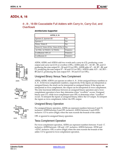
ADD4, 8, 164-, 8-, 16-Bit Cascadable Full Adders with Carry-In, Carry-Out, and OverflowAArchitectures SupportedADD4, ADD8, and ADD16 add two words and a carry-in (CI), producing a sum output and carry-out (CO) or overflow (OFL). ADD4 adds A3 – A0, B3 – B0, and CI producing the sum output S3 – S0 and CO (or OFL). ADD8 adds A7 – A0, B7 – B0, and CI, producing the sum output S7 – S0 and CO (or OFL). ADD16 adds A15 – A0, B15 – B0 and CI, producing the sum output S15 – S0 and CO (or OFL).Unsigned Binary Versus Twos ComplementADD4, ADD8, ADD16 can operate on either 4-, 8-, 16-bit unsigned binary numbers or 4-, 8-, 16-bit twos-complement numbers, respectively. If the inputs are interpreted as unsigned binary, the result can be interpreted as unsigned binary. If the inputs are interpreted as twos complement, the output can be interpreted as twos complement. The only functional difference between an unsigned binary operation and a twos-complement operation is how they determine when “overflow” occurs. Unsigned binary uses CO, while twos-complement uses OFL to determine when “overflow” occurs. To interpret the inputs as unsigned binary, follow the CO output. To interpret the inputs as twos complement, follow the OFL output.Unsigned Binary OperationFor unsigned binary operation, ADD4 can represent numbers between 0 and 15, inclusive; ADD8 between 0 and 255, inclusive; ADD16 between 0 and 65535, inclusive. CO is active (High) when the sum exceeds the bounds of the adder.OFL is ignored in unsigned binary operation.T wos-Complement OperationFor twos-complement operation, ADD4 can represent numbers between -8 and +7, inclusive; ADD8 between -128 and +127, inclusive; ADD16 between -32768 and +32767, inclusive. OFL is active (High) when the sum exceeds the bounds of the adder. CO is ignored in twos-complement operation.ADD4, 8, 16Spartan-II, Spartan-IIE No Spartan-3No Virtex, Virtex-ENo Virtex-II, Virtex-II Pro, Virtex-II Pro X NoXC9500, XC9500XV , XC9500XL Primitive CoolRunner XPLA3Primitive CoolRunner-IIPrimitiveADD8 Implementation Spartan-II, Spartan-IIE, Virtex, Virtex-E Libraries GuideADD8 Implementation Spartan-3, Virtex-II, Virtex-II Pro, Virtex-II Pro XADD4 Implementation XC9500/XV/XL, CoolRunner XPLA3, CoolRunner-II Libraries GuideADD8 Implementation XC9500/XV/XL, CoolRunner XPLA3, CoolRunner-II UsageThis design element is schematic or inference only -- no instantiation.VHDL Inference Code (ADD4)architecture Behavioral of ADD issignal sum: std_logic_vector(WIDTH-1 downto 0);signal zeros: std_logic_vector(WIDTH-1 downto 0) := (others => '0'); beginprocess (CI, A, B, sum)beginsum <= ('0' & A) + ('0' & B) + (zeros & CI);S <= sum(WIDTH-1 downto 0);CO <= sum(WIDTH);end process;end Behavioral;Verilog Inference Code (ADD4)always @ (A or B or CI)begin{CO,sum} <= A + B + CI;end Libraries Guide。
vhdl全加器实验报告

vhdl全加器实验报告VHDL全加器实验报告引言:在现代计算机科学中,加法运算是基本而重要的运算之一。
全加器是一种用于实现二进制加法的电路。
本次实验旨在使用VHDL语言设计和实现一个全加器电路,并通过仿真和测试验证其正确性和可行性。
一、全加器的原理和设计思路全加器是由两个半加器和一个额外的输入信号组成的电路。
它的输入包括两个二进制数位的输入信号A和B,以及一个来自上一位的进位信号Cin。
输出包括一个和位输出信号S和一个进位输出信号Cout。
全加器的真值表如下:A B Cin S Cout0 0 0 0 00 0 1 1 00 1 0 1 00 1 1 0 11 0 0 1 01 0 1 0 11 1 0 0 11 1 1 1 1根据全加器的真值表,我们可以得到以下逻辑表达式:S = A ⊕ B ⊕ CinCout = (A ∧ B) ∨ (Cin ∧ (A ⊕ B))基于以上原理和逻辑表达式,我们可以使用VHDL语言来实现全加器电路。
二、VHDL全加器电路的设计和实现1. 实体声明:首先,我们需要在VHDL代码中声明全加器的输入和输出信号。
代码如下:entity FullAdder isport (A, B, Cin: in std_logic;S, Cout: out std_logic);end FullAdder;2. 架构实现:接下来,我们需要在VHDL代码中实现全加器的逻辑功能。
代码如下:architecture behavior of FullAdder isbeginS <= A xor B xor Cin;Cout <= (A and B) or (Cin and (A xor B));end behavior;三、VHDL全加器电路的仿真和测试1. 仿真环境的搭建:为了验证全加器电路的正确性,我们需要使用VHDL仿真工具进行电路的仿真。
这里我们使用ModelSim进行仿真。
基于VHDL的16进制计数器的程序设计

实事求是实验课程名称通信系统集成电路设计实验项目名称 Quartus II实验操作实验一:Quartus II操作及16进制加法器1.实验目的a)熟悉熟悉EDA工具QuartusII及modelsim软件的使用方法。
掌握用quartus ii或其他EDA软件对VHDL源程序进行编译、调试、修改、波形仿真。
b)学习VHDL程序的软件及硬件的编写及仿真方法并熟练掌握VHDL程序的编写方法和注意事项。
c)编写、调试出16进制计数器的程序,仿真出波形。
d)在上面的基础上做出PCM9程序,并仿真出波形数据。
2.实验器材a)电脑中要有Quartus II 软件b)电脑中要有Modelsim软件3.实验内容a)熟悉Quartus II和modelsim软件,并将两个软件进行配置,使软件可以用于为后面的软件进行调试。
b)尽量自己编写VHDL程序,做16进制的计数器实验,包括计数器程序和测试平台。
c)了解模块设计方法和思想,并设计并搭建测试平台。
实事求是实事求是4. 实验要求a) 熟悉两个软件并配置好相关环境。
熟悉两个软件并配置好相关环境。
b) 编写实验用的VHDL 程序。
程序。
c) 使用Quartus II 编译,查找错误并修改到正确无误。
编译,查找错误并修改到正确无误。
d) 使用Quartus II 仿真,生成波形文件。
仿真,生成波形文件。
e) 保存相关文件,并书写实验报告。
保存相关文件,并书写实验报告。
5. 实验步骤及结果a) 建立工程并加入16进制模块和测试平台。
进制模块和测试平台。
1. 建立工程。
建立工程。
在菜单栏里有在菜单栏里有 file àNew Project Wizard ,点击Next 到这个界面。
到这个界面。
输入项输入项目名称。
后点击Finish ,完成项目的创建。
,完成项目的创建。
2. 建立文件。
建立文件。
在菜单栏里有在菜单栏里有 file àNew ,跳转到下面这个界面。
16位双译码器的VHDL实现

16位双译码器的VHDL实现软件:Quartus ii 8.1设计思路:先设计一个2-4译码器,在2-4译码器的基础上设计一个8-256双译码器,然后在8-256双译码器的基础上设计出16-65536双译码器。
双译码器需要与门阵列,而且与门阵列的设计才是此次设计的难点。
为简化设计,与门阵列单独设计,本文先设计了4*4的与门阵列,然后将4*4的与门阵列扩展成4*16的与门阵列,然后又将4*16的与门阵列扩展成16*16的与门阵列,然后又将16*16的与门阵列扩展成了16*256的与门阵列,最后又将16*256的与门阵列扩展成了256*256的与门阵列。
首先,先设计一个2-4译码器,代码如下:library ieee;use ieee.std_logic_1164.all;entity decoder2to4 isport(en:in std_logic;x:in std_logic_vector(1 downto 0);y:out std_logic_vector(3 downto 0));end decoder2to4;architecture rtl of decoder2to4 isbeginprocess(en,x)beginif(en='1')thencase x iswhen "00" => y<="0001";when "01" => y<="0010";when "10" => y<="0100";when "11" => y<="1000";when others => y<="0000";end case;elsey<="0000";end if;end process;end rtl;由2-4译码器扩展得到4-16双译码器需要用到4*4的与门阵列,所以需要设计一个4*4的与门阵列,代码如下:library ieee;use ieee.std_logic_1164.all;entity and4mul4 isport(x:in std_logic_vector(3 downto 0);y:in std_logic_vector(3 downto 0);z:out std_logic_vector(15 downto 0));end and4mul4;architecture structure of and4mul4 is component and2to1port(a,b: in std_logic;y: out std_logic);end component;beging1:for i in 3 downto 0 generateu1:and2to1 port map (x(0),y(i),z(i));end generate;g2:for i in 3 downto 0 generateu2:and2to1 port map (x(1),y(i),z(4+i));end generate;g3:for i in 3 downto 0 generateu3:and2to1 port map (x(2),y(i),z(8+i));end generate;g4:for i in 3 downto 0 generateu4:and2to1 port map (x(3),y(i),z(12+i));end generate;end structure;其中,与门and2to1的代码如下:library ieee;use ieee.std_logic_1164.all;entity and2to1 isport(a,b: in std_logic;y: out std_logic);end and2to1;architecture rtl of and2to1 isbeginprocess(a,b)variable comb : std_logic_vector(1 downto 0);begincomb := a & b;case comb iswhen "00" => y <= '0';when "01" => y <= '0';when "10" => y <= '0';when "11" => y <= '1';when others => y <= 'X';end case;end process;end rtl;由2-4译码器及4*4的与门阵列,扩展成4-16双译码器,代码如下:library ieee;use ieee.std_logic_1164.all;entity dec4to16 isport(en:in std_logic;x:in std_logic_vector(1 downto 0);y:in std_logic_vector(1 downto 0);z:out std_logic_vector(15 downto 0));end dec4to16;architecture structure of dec4to16 iscomponent decoder2to4port(en:in std_logic;x:in std_logic_vector(1 downto 0);y:out std_logic_vector(3 downto 0));end component;component and4mul4port(x:in std_logic_vector(3 downto 0);y:in std_logic_vector(3 downto 0);z:out std_logic_vector(15 downto 0));end component;signal c1:std_logic_vector(3 downto 0);signal c2:std_logic_vector(3 downto 0);beginu1:decoder2to4 port map(en,x,c1);u2:decoder2to4 port map(en,y,c2);u3:and4mul4 port map(c1,c2,z);end structure;然后,为了将4-16双译码器扩展成8-256双译码器,需要16*16的与门阵列。
VHDL实现16位全加器.doc

VLSI 电路和系统设计设计题 2:CMOS数字集成电路设计用 VHDL 语言实现十六位全加器:托列吾别克·马杰尼班级:电路与系统 01 班学号: 12013/11/24基于 VHDL 的 16 位全加器的设计1.1设计题目的容及要求1.1.1目的:CMOS 数字集成电路设计流程及数字集成电路自动化设计,包括功能验证、 VHDL/Verlog建模、同步电路设计、异步数据获取、能耗与散热、信号完整性、物理设计、设计验证等技术1.1.2容:主要实验容是用0.18μm 数字 CMOS 工艺, VHDL或 Verlog 设计一个16 位全加器,用 Synthesis仿真工具验证功能,电路合成,及性能检测。
1.1.3主要测试参数及指标围:16 位的全加器主要的设计指标是高于1GHz 的频率,功耗,物理面积大小等参数。
1.2全加器的组成和原理分析全加器是常用的组合逻辑模块中的一种,对全加器的分析和对组合逻辑电路的分析一样。
组合逻辑电路的分析,就是找出给定电路输入和输出之间的逻辑关系,从而了解给定逻辑电路的逻辑功能。
组合逻辑电路的分析方法通常采用代数法,一般按下列步骤进行:(1)根据所需要的功能,列出真值表。
(2)根据真值表,写出相应的逻辑函数表达式。
(3)根据真值表或逻辑函数表达式,画出相应的组合逻辑电路的逻辑图[1]。
(4)用 VHDL 编写程序在 QUARTUSⅡ上进行模拟,并分析结果的正确性。
1.3 全加器简介全加器是组合逻辑电路中最常见也最实用的一种,考虑低位进位的加法运算就是全加运算,实现全加运算的电路称为全加器。
它主要实现加法的运算,其中分为并行全加器和串行全加器,所谓并行就是指向高位进位时是并行执行的,而串行就是从低位到高位按顺序执行,为了提高运算,必须设法减小或消除由于进位信号逐级传递所消耗的时间,为了提高运算速度,制成了超前进位加法器,这是对全加器的一种创新[2]。
1.3.1半加器的基本原理如果不考虑有来自低位的进位将两个 1 位二进制数相加,称为半加。
16位ALUVHDL实现源程序

思考题:编写十六位运算器的VHDL程序——MYALU实验任务:用CPT16 的扩展实验板上的开关K3 、K2、K1、K0做为输入、八段数码管LED0..LED3做为输出,用VHDL语言编写程序,下载到EP1C6中,实现十六位模型机的MY ALU 功能见下表。
实验说明:在MY ALU.VHD程序设计中,定义A 为16位累加器,其值由K3 、K2 两组开关输入;W 为16位工作寄存器,其值由K1、K0 两组开关共输入;S2、S1、S0 为运算功能控制位,接在K4开关的第2、1、0个开关上,根据S2、S1、S0 的不同,MY ALU 实现不同功能D为运算结果输出,显示在四位八段管LED3..LED0上;CIn 为进位输入,由K4 开关组的第3 个开关输入;COut 为进位输出,用发光二极管L0 显示其状态。
逻辑功能:library ieee; ------库程序包调用use ieee.std_logic_1164.all;use ieee.std_logic_arith.all;use ieee.std_logic_unsigned.all;entity asanxia is ------实体:电路外观配置port(inA : IN UNSIGNED(15 DOWNTO 0); -- K3, K2 inAinW : IN UNSIGNED(15 DOWNTO 0); -- K1, K0 inWoutLED : OUT STD_LOGIC_VECTOR(15 DOWNTO 0); -- LED3~LED0 outLEDinC : IN STD_LOGIC_VECTOR(2 DOWNTO 0); --Control Input inCCin:IN STD_LOGIC; --C Input k4.3 CinCout: OUT STD_LOGIC -- C Output L0 Cout);end asanxia;architecture arch of asanxia is ------结构体:电路功能描述--中间变量signal c:std_logic_vector(15 downto 0); --暂存进位信号signal q:UNSIGNED(15 downto 0); --暂存各位数值beginprocess(inC,inA,inW,Cin)begincase inC iswhen "000"=> ------加法:A+B ;A+B+1q(0)<=inA(0)xor inW(0)xor Cin;c(0)<=(inA(0) and inW(0))or (inW(0)and Cin)or (inA(0)and Cin);--inA(0),inW(0),Cin有两个以上为1即产生进位。
基于VHDL的简易16位模型机设计与实现

基于VHDL 的简易16位模型机设计与实现收稿日期:2017-09-18基金项目:南昌航空大学教改资助项目(“计算机组成与结构”创新创业教育课程培育项目,KCPY1518)作者简介:张胜(1968-),男(汉族),湖北罗田人,南昌航空大学,博士,副教授,研究方向:无线传感器网络、人工智能、数据挖掘、GPS/GIS 等。
近年来,随着电子设计自动化技术的不断发展,基于现场可编程(FPGA )技术设计嵌入式CPU 突破了原有的技术瓶颈,使产品的开发周期大为缩短,性价比也大幅提高。
特别是随着硬件描述语言(VHDL )综合工具功能和性能的提高,计算机中许多重要的元器件,甚至是整个CPU 都用硬件描述语言来设计和表达,形成了所谓的单片系统———SOC 和SOPC 。
本文是计算机组成原理课程中综合实验的内容之一,以计算机基本组成和原理为基础,利用EDA 中的VHDL 技术在Cyclone Ⅱ系列的FPGA 芯片上设计、实现一个16位模型计算机,主要侧重于CPU 设计,要求能够实现加减乘除算术运算、与或非逻辑运算以及左右移运算等基本功能。
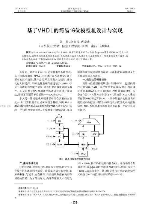
一、模型机的硬件设计简易16位模型机模块设计如图1所示,包括的部件有存储器(RAM )、内存缓存寄存器(MBR )、内存地址寄存器(MAR )、控制器(CU )、程序计数器(PC )、指令寄存器(IR )、缓冲寄存器(BR )、累加器(ACC )、乘法寄存器(MR )和运算器(ALU )。
图中带箭头的粗线表示模型机的数据流,带箭头的细线表示模型机中的控制信息(CS )。
系统将累加器和乘法寄存器一并设计在运算器中。
张胜,李方云,曹家庆(南昌航空大学信息工程学院,江西南昌330063)摘要:在QuartusII6.0的IDE 环境下利用VHDL 技术设计并实现了一个基于Cyclone Ⅱ系列的FPGA 芯片的16位模型机,能够实现加减乘除算术运算、与或非逻辑运算以及进行算术左右移运算。
位二进制全加器VHDL的设计

4.4 计数器设计
表面上具有双向端口的功能,但实际上其输入功能是不完整的,它只能将自己输出的信 号再反馈回来,并不含有的功能。
表式Q <= Q + 1的右项与左项并非处于相同的时刻内,对于时序电路,除了传输延时外, 前者的结果出现于当前时钟周期;后者,即左项要获得当前的Q + 1,需等待下一个时钟周 期。
... ;
作用:表示多分支情况的选择语句,各分支无优先级。 执行:每次启动语句,只选择执行其中一个分支的语句。
注意:(1)对所有的情况都要赋值,否则会综合成锁存器。 (2)语句只能在语句中使用。 (3)与语句的区别。
2. 标准逻辑矢量数据类型
在使用中,必须注明其数组宽度,即位宽,如: B : (7 0) --8位数 或 A :(1 4)--4位数
检测是否允许计数
< "1001"
+ 1; 允许计数
( =>‘0’)等于或者大于9,计数值清零
;
;
;
= “1001” <= ‘1’; 计数等于9,输出进位信号
<= '0';
;
<= ;
将计数值向端口输出
;;ຫໍສະໝຸດ ▼ 相关语法说明5 一般加法计数器设计
1. 变量
2.
变量赋值符号 := 如‘1’
3.
变量的功能:用于数据暂存单元,只能在语句中定义和使用。
<= a & b ; ()
"00" => <='0'; <='0' ; "01" => <='1'; <='0' ; "10" => <='1'; <='0' ; "11" => <='0'; <='1' ; => ; ; ; 1;
VHDL加法器与乘法器

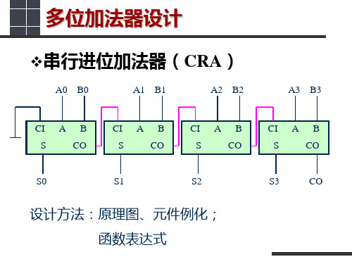
串行进位加法器( 串行进位加法器(CRA) )
A0 B0 A1 B1 A2 B2 A3 B3
CI S
A
B CO
CI S
A
B CO
CI S
A
B CO
CI S
A
B CO
S0
S1
S2
S3
CO
设计方法:原理图、元件例化; 函数表达式
多位加法器设计
选择进位加法器( 选择进位加法器(CSLA) )
移位相加乘法器
BEGIN IF ST = '1' THEN -REGA := "00000000" & A; REGB := B; RESULT <= (OTHERS => '0'); SOUT <= '0'; REGRES := (OTHERS => '0'); CNT := (OTHERS => '0'); ELSIF CLK'EVENT AND CLK='1' THEN -IF REGB(0)='1' THEN -REGRES := REGRES + REGA; END IF; REGA(15 DOWNTO 1) := REGA(14 DOWNTO 0); -REGA(0):= '0'; -REGB(6 DOWNTO 0) := REGB(7 DOWNTO 1); -CNT := CNT + 1; -IF CNT="000" THEN -RESULT <= REGRES; -SOUT <= '1'; REGA := "00000000" & A; REGB := B;-REGRES := (OTHERS => '0'); -END IF; END IF; END PROCESS; END ARCHITECTURE; 初始化, 初始化,置位
- 1、下载文档前请自行甄别文档内容的完整性,平台不提供额外的编辑、内容补充、找答案等附加服务。
- 2、"仅部分预览"的文档,不可在线预览部分如存在完整性等问题,可反馈申请退款(可完整预览的文档不适用该条件!)。
- 3、如文档侵犯您的权益,请联系客服反馈,我们会尽快为您处理(人工客服工作时间:9:00-18:30)。
[键入公司名称][键入文档标题][键入文档副标题]姓名:托列吾别克•马杰尼班级:电路与系统01班学号:201221020141[键入公司名称]2013/11/24基于VHDL的16位全加器的设计1.1设计题目的内容及要求i.i.i 目的:CMOS数字集成电路设计流程及数字集成电路自动化设计,包括功能验证、VHDL/Verlog建模、同步电路设计、异步数据获取、能耗与散热、信号完整性、物理设计、设计验证等技术1.1.2内容:主要实验内容是用0.18阿数字CMOS工艺,VHDL或Verlog设计-个16位全加器,用Synthesis仿真工具验证功能,电路合成,及性能检测。
1.1.3主要测试参数及指标范围:16位的全加器主要的设计指标是高于1GHz的频率,功耗,物理面积大小等参数。
1.2全加器的组成和原理分析全加器是常用的组合逻辑模块中的一种,对全加器的分析和对组合逻辑电路的分析一样。
组合逻辑电路的分析,就是找出给定电路输入和输出之间的逻辑关系,从而了解给定逻辑电路的逻辑功能。
组合逻辑电路的分析方法通常采用代数法,一般按下列步骤进行:(1)根据所需要的功能,列出真值表。
(2)根据真值表,写出相应的逻辑函数表达式。
(3)根据真值表或逻辑函数表达式,画出相应的组合逻辑电路的逻辑图(4)用VHDL编写程序在QUARTUS U上进行模拟,并分析结果的正确性。
1.3全加器简介全加器是组合逻辑电路中最常见也最实用的一种,考虑低位进位的加法运算就是全加运算,实现全加运算的电路称为全加器。
它主要实现加法的运算,其中分为并行全加器和串行全加器,所谓并行就是指向高位进位时是并行执行的,而串行就是从低位到高位按顺序执行,为了提高运算,必须设法减小或消除由于进位信号逐级传递所消耗的时间,为了提高运算速度,制成了超前进位加法器,这是对全加器的一种创新[2]。
1.3.1半加器的基本原理如果不考虑有来自低位的进位将两个1位二进制数相加,称为半加。
实现半加运算的电路称为半加器。
按照二进制加法运算规则可以列出如表2所示的半加器真值表,其中A、B 是两个加数,S是相加的和,CO是向咼位的进位。
将S、CO和A、B的关系写成逻辑表达式则得到S=A B+A B=A+BCO=AB因此,半加器是由一个异或门和一个与门组成的,如图1所示。
图1半加器原理图1.3.2 一位全加器的原理全加器执行加数,被减数和低位来的进位信号相加,并根据求和结果给出该进位信号。
(1)根据全加器所需要的功能,我们可以设计出一位全加器的组合逻辑框图。
如图2所示。
G HXi柠G图2一位全加器的逻辑图(2根据逻辑图我们可以写出各个器件的逻辑功能。
C i = X i 丫i C i-i +X i 丫i C i-i +X i 丫i C i-i +X i 丫i C i-i = (X i ①丫i)C i-i +X i 丫iF i = XY C / + X i YC M +XY C / + XY C / = X i®Y i®C M(3)由上面可得。
X i和Y i为两个输入的一位二进制书,C i-i为低位二进制数相加的进位输出到本位的输入,则F i为本位二进制数X i、Y i和低位进位输入C i-i的相加之和,C i为X i、Y i和低位进位输入C M相加向高位的进位输出。
因此,该电路可以完成一位二进制数全加的功能,称为全加器。
此电路的真值表如表2所示。
表2 一位全加器真值表1.4十六位全加器的设计设计16位的全加器思路非常简单且清晰,第一种方法就是先设计一个半加器和一个或门,然后两个半加器合并成一个一位的全加器,最后用16个一位的全加器组合成为一个16位的全加器;第二种方法就是先设计一个一位的全加器, 然后在用16个串联或并联就组成了一个16位的全加器,而本次设计采用采用的是第一种方法。
十六位全加器有十六个一位全加器的级联组成的,最低位的借位信号时整个全加器的借位信号Ci n,最高位的进位信号是十六位全加器的进位信号,每位之间通过进位信号链接,两个十六位加数的每一位并联输入,和数SUM的每-位并联输出,完成两个十六位的数的加法。
1.5用VHDL编写代码实现16位全加器本次实验使用Altera FPGA/CPLD 的开发工具Quartus U,利用编写VHDL代码设计方法设计一个16位加法器,并用Quartus的综合仿真工具实现电路的综合,电路功能的验证,并最后查看综合后的RLT电路框图来验证设计与原逻辑设计符不符合要求,我们还可以借用powerplay功率分析工具对设计后的电路进行功耗分析。
本次设计有一个顶层模块(16位全加器)和三个底层模块,它们分别为一位全加器和组成一位全加器的半加器模块和或门模块。
因此我们要用从底层到顶层的设计思路,以半加器+或门一一>一位全加器一一>16位全加器的为设计顺序。
以下为半加器和活门的VHDL程序代码(1)半加器的VHDL代码library ieee;use ieee.std_logic_1164.all;use ieee.std_logic_arith.all;use ieee.std_logic_ un sig ned.all;en tity h_adder isport(a,b:in std」o gic;co:out std_logic;so:out std_logic );end h_adder;architecture one of h_adder isbegi nso<=a xor b;co<=a and b;end one;(2) 或门的VHDL代码library ieee;use ieee.std_logic_1164.all;use ieee.std_logic_arith.all;use ieee.std_logic_ un sig ned.all;en tity or2a isport(a,b:in std」o gic;c:out std」o gic );end or2a;architecture one of or2a isbegi nc<=a or b;end one;由全加器的逻辑图可以看出,全加器由两个半加器和一个或门组成。
在VHDL语言中我们可以在一个模块的代码中用component语句调用低层的模块这样可以避免写更多的繁琐的代码,也可以提高程序的可读性,也有利于实际电路在延时等关键技术性问题上的优越性。
(3) —位全加器的VHDL代码library ieee;use ieee.std_logic_1164.all;use ieee.std_logic_arith.all;use ieee.std_logic_ un sig ned.all;en tity f_adder isport(ai n:in std」o gic;bin:in std_logic;cin:in std_logic;coutf:out std」o gic;sumf:out std_logic );end f_adder;architecture one of f adder iscomp onent h_adderport(a:in std」ogic;b:in std」o gic);end comp onent;comp onent or2aport(a:in std _lo gic;b:in std_logic);end comp onent;sig nal d,e,f:std」o gic;begi nu1:h_adder port map(a=>a in, b=>b in, co=>d,so=>e);u2:h_adder port map(a=>e,b=>c in, co=>f,so=>sumf);u3:or2a port map(a=>d,b=>f,c=>coutf);end one;从上述的设计思路中和全加器的级联设计方案中看到,实现16位全加器的关键是实现每级全加器到下一级全加器的信号的控制,以此实现模块之间的协调和整个系统的稳定性。
在实现16加法器中我们同样用上述的comp on e nt语句, 在顶层中调用底层的模块,并巧妙地实现每个模块之间的级联。
以下为一种设(4) 16位加法器的VHDL代码library ieee;use ieee.std_logic_ un sig ned.all;en tity n ew_adder16 isport(a:in std」ogic_vector(15 downto 0);b:in std_logic_vector(15 downto 0);cin:in std_logic;sum:out std_logic_vector(15 downto 0););end;architecture one of n ew_adder16 is comp onent f_adderport(ain:in std」ogic;bin:in std_logic;cin:in std_logic coutf:out std」o gic;sumf:out std_logic );end comp onent;sig nal temp:std_logic_vector(16 dow nto 0);beg intemp(0)<=ci n;add:for i in 0 to 15 gen erate loopadd:f_adder port map(a in=>a(i).bin=>b(i).cin=>temp(i).coutf=>temp(i+1).sumf=>sum(i));end gen erate add;cout<=temp(16);end one;上述代码中用for…gen erate循环语句和compo ne nt语句的调用语句实现15 位信号的加法。
因为for…generate不像for….loop那样顺序执行而是并行执行的,使用了for...loop,所以对应RTL Viewer就比较复杂,所以for…gen erate语句更有效。
2.1用QuartusII实现16位全加器电路的综合仿真1) 以new_adder16为工程名新建一个工程,我们可以预先设置硬件的选择,本次设计用MAX系列芯片。
2) 新建四个VHDL文件,分别编写进上四个模块的VHDL代码。
顶层模块的文件名要工程名一致,在此为n ew_adder16.vhd其余的文件名跟模块名要一致,以便于以后的综合和验证过程的调试。
3) 实现编译和综合,若无误则可以仿真了,综合后Quartus软件给出设计中所用到的逻辑单元,弓I脚等信息,如图4所示。
