DCD材料说明书
西部磁性材料有限公司产品说明书:紧凑型电路板电源电路电压稳定器

1 West Coast Magnetics Advancing Power ElectronicsFOIL WINDINGS FOR SMPS INDUCTORS AND TRANSFORMERS Weyman Lundquist, CEO and Engineering Manager2•Solid wire⏹Litz wire⏹FoilTYPES OF WINDINGSLowest costLow DC resistance High AC winding lossEasy to wind Highest costHigher DC resistancePotential for low AC winding lossPractical limitation of 500 kHz due to lossInexpensiveVery Low DC resistancePotential for low AC winding loss3proximityskin dc rmsac dc dctotal P P R IR I P +++=2,22,rmsac ac ac IP R =dcdcdc R I P 2=Resistive lossEddy-currentlossdc lossac lossacrmsac ac R IP 2,=“ac resistance”WINDING LOSS COMPONENTS4PROXIMITY EFFECTJxOriginal drawing from SnellingB-Fieldxxx xxx xxx xxxx oo ooo ooo ooo ooCurrent DensityInduced CurrentMain Current⏹Proximity Effect⏹An isolated conductor is placed in an uniform external field ⏹External field results from other wires and windings near the conductor (transformer) and from the field present in the core winding window (inductor)PROXIMITY EFFECT55TransformerInductor Conductor Complexity Core gap Wave form Dowell yes yes Solid wire, foil 1 D No Sinusoidal Litz opt yes no Litz 2D Yes Sinusoidal Shape Opt no yes Litz 2D Yes Any Transformer Inductor Conductor Complexity Core gap Wave form Dowell Yes yes Solid wire, foil 1 D No Sinusoidal Litz opt Yes No Litz 2D Yes Sinusoidal Shape Opt No Yes Litz 2D Yes Any AnsysYesYesAll2D 3DYesYes•Design and Test Verification•Measure DCR (high accuracy)•Thermal measurement under load•Measure ESR (good for comparison of different windings, includes core loss induced by LCR meter)•Isolate winding loss using Network Analyzer *•Simulation Software* C.R. Sullivan, “A Step by Step Guide to Extracting Winding Resistance from an Impedance Measurement”, IEEE Apec 20176•Strategies for Loss Minimization in Foil Windings6Optimize foil thickness Minimize number of layersShape foil to take advantage of core geometry effects (WCM, Dartmouth Patent)Use multiple parallel foils and swap layersUse different foil thicknesses for different turns.Use a parallel litz or thin foil winding in the vicinity of a gap Interleave winding (transformers only)Use a low permeability material for core legSTUDYOPTIMIZATIONDesign and Test Verification:Model litz options: Litz optTest ESR from 100 kHz to 500 kHz to comparefoil and litz.Choose lowest loss option.Litz opt result:48 awg litz is lowest loss option.46 awg litz chosen due to cost.100 kHz: optimal number of strands: 3210500 kHz: optional number of strands: 871Choose 2700 strands, single layer, position asindicated in cross sectional view.9TRANSFORMER WINDING LOSS –CASE STUDY10RESULTS –TRANSFORMER10 DESIGNLitz is lowest loss optionTransformer constructed with 2700/46.Leakage L not sufficiently high.Bench testing indicates acceptable performance with room for loss reduction. NEXT STEPUse leakage layer to reduce space between windings, increase leakage L, and reduce loss. Investigate lower capacitance foil winding.1111INDUCTOR WINDING LOSS –CASE STUDY Inductance: 700 nHDC Current: 10 ampsRipple: 23 AppFrequency: 500 kHzDesign: 4 turns on EP13, gap of 1 mmSolution: Shape opt optimization, test ESR and DCR to estimate lossCompare to full foil and shaped foil.Shaped foil/cutout foil patent issued and second patent pendingWCM and DartmouthInductor Window Cross Section –Center Leg Gap12 Field Lines: Shape Opt Foil Cutout Cross Section Wire Placement: ShapeoptESR vs. Frequency Measurement 700 nH Inductor13Cutout: patent pendingInductor Total Winding Loss Including DC15Ripple magnitude above which litz has lower loss than copper foil for a 4 turn boost inductor100 kHz 63%6300200 kHz 37% 7400300 kHz 26%7800400 kHz 23% 9200500 kHz 20% 100001 MHz 18% 180002 MHz 15% 30000FrequencyPercent ProductWCM Shaped16 Foil InductorsLow loss gapped ferrite core, shaped foilwinding.Patent pending: Dartmouthand WCM17 Comparison of 10 uH, 55amp inductorsShaped Foil IronNickelToroidHighIronToroidHelicalCoilBased on 2015 WCM study, copies availableWinding Loss: Gapped Ferrite18 Cutout Patent issued: Dartmouth and WCMCONCLUSIONS19 Cut out foil for gapped inductor designs is the lowest loss option for inductors with DC current upto a ripple frequency product of about 7000. (% ripple * kHz)Both foil and litz are usable for inductors at frequencies up to 2 MHz as long as the ripple is lessthan 20%.Litz is very expensive with the cost increasing exponentially with frequency. In the cases noted inthe presentation the litz wire cost was 60% to 70% of the total material cost.For transformers, many high power applications require more turns, making foil windingoptimization critical.For gapped inductors shaped cutout foil has lower loss than full width foil, provided copper crosssection is the same.Future work to further examine effect of foil thickness as well as methods of reducing windingcapacitance in foil windings to extend performance to higher ripple and frequency values andto windings with more layers.Shaped foil/cutout foil patent issued and second patent pending WCM and Dartmouth20Thank you.。
产品材质说明及技术规范说明书

产品材质说明及技术规范说明书天长市联华科技有限公司生产的科教设备,实验室设备等产品均采用先进的加工设备,精湛的工艺,新颖的造型,流畅的线条,明快的色彩等视觉效果,更注重产品内在的质量的完美。
为确保产品的质量,本厂在材料选用上严格履行如下规定与选择:一、边实验台钢架:采用特制型材(50*30*1.5),经酸洗磷化,表面环氧树脂静电粉沫喷涂,进防腐处理,防腐性能良好,外表美观,承重每延米500公斤以上;基材:均采用滁州华能产或江苏东盾产双浸面优质高压三聚氰胺板,此板材料通过环保部门认定的绿色工业产品;mm厚美国威盛亚实芯理化板,边延加厚弧形收边,高压成型,结构坚固耐用。
具有抗强酸、强碱、耐磨、耐高温、耐腐蚀、防水、防霉、易清洗等功能。
滑轨:采用德国海福乐静音滑轨;拉手:弧形式不锈钢拉手;铰链:采用意大利FIRA产优质“三段力”铰链,具有灵活、静音、拆装方便、使用寿命长、开合达三十万次以上,耐腐蚀性能强;插座:采用上海松日万用插座(多孔,多功能,带安全门插座);地脚:选用实验室专用不锈钢地脚,外加防腐伸缩套,可调节0—50mm,确保台面的高度水平;—4平方铜芯线(确保实验操作时设备运行安全);二、色谱台钢架:采用特制型材(50*30*1.5),经酸洗磷化,表面环氧树脂静电粉沫喷涂,进防腐处理,防腐性能良好,外表美观,承重每延米500公斤以上;基材:均采用滁州华能产或江苏东盾河产双浸面优质高压三聚氰胺板,此板材料通过环保部门认定的绿色工业产品;mm厚美国威盛亚实芯理化板,边延加厚弧形收边,高压成型,结构坚固耐用。
具有抗强酸、强碱、耐磨、耐高温、耐腐蚀、防水、防霉、易清洗等功能。
滑轨:采用德国海福乐静音滑轨;拉手:弧形式不锈钢拉手;铰链:采用意大利FIRA产优质“三段力”铰链,具有灵活、静音、拆装方便、使用寿命长、开合达三十万次以上,耐腐蚀性能强;插座:采用上海松日万用插座(多孔,多功能,带安全门插座);地脚:选用实验室专用不锈钢地脚,外加防腐伸缩套,可调节0—50mm,确保台面的高度水平;—4平方铜芯线(确保实验操作时设备运行安全);三、高温台钢架:采用特制型材(50*30*1.5),经酸洗磷化,表面环氧树脂静电粉沫喷涂,进防腐处理,防腐性能良好,外表美观,承重每延米500公斤以上;基材:均采用滁州华能产和江苏东盾产双浸面优质高压三聚氰胺板,此板材料通过环保部门认定的绿色工业产品;台面:选用15mm厚优质花岗岩,边延加厚30mm进行弧形收边,具有耐高温、耐腐蚀、耐酸碱、抗震动等功能;柜体:18mm厚中密度板外粘压美国威盛亚防火板,具有耐酸碱、耐腐蚀、防火、防水等功能;滑轨:采用德国海福乐静音滑轨;拉手:弧形式不锈钢拉手;铰链:采用意大利FIRA产优质“三段力”铰链,具有灵活、静音、拆装方便、使用寿命长、开合达三十万次以上,耐腐蚀性能强;地脚:选用实验室专用不锈钢地脚,外加防腐伸缩套,可调节0—50mm,确保台面的高度水平;—4平方铜芯线(确保实验操作时设备运行安全);四、转角台钢架:采用特制型材(50*30*1.5),经酸洗磷化,表面环氧树脂静电粉沫喷涂,进防腐处理,防腐性能良好,外表美观,承重每延米500公斤以上;基材:均采用滁州华能产和江苏东盾产双浸面优质高压三聚氰胺板,此板材料通过环保部门认定的绿色工业产品;柜体:18mm厚中密度板外粘压美国威盛亚防火板,具有耐酸碱、耐腐蚀、防火、防水等功能;mm厚美国威盛亚实芯理化板,边延加厚弧形收边,结构坚固耐用。
宝山钢铁股份有限公司企业标准-DC系列
宝山钢铁股份有限公司企业标准宝钢资源查询冷连轧低碳钢板及钢带(Q/BQB 403-2009 代替Q/BQB 403-2003、BZJ492-2004)1 范围本标准规定了冷连轧低碳钢板及钢带的分类和代号、尺寸、外形、重量、技术要求、检验和试验、包装、标志及检验文件等。
本标准适用于宝山钢铁股份有限公司生产的厚度为0.17mm~3.5mm的冷连轧低碳钢板及钢带(以下简称钢板及钢带)。
2 规范性引用文件下列文件中的条款通过本标准的引用而成为本标准的条款。
凡是注日期的引用文件,其随后所有的修改单(不包括勘误的内容)或修订版均不适用于本标准,然而,鼓励根据本标准达成协议的各方研究是否可使用这些文件的最新版本。
凡是不注日期的引用文件,其最新版本适用于本标准。
GB/T 222-2006 钢的成品化学成分允许偏差GB/T 223 钢铁及合金化学分析方法GB/T 228-2002 金属材料室温拉伸试验方法GB/T 2523-2008 冷轧金属薄板(带)表面粗糙度和峰值数的测量方法GB/T 2975-1998 钢及钢产品力学性能试验取样位置及试样制备GB/T 4336-2002 碳素钢和中低合金钢火花源原子发射光谱分析方法(常规法)GB/T 5027-2007 金属薄板和薄带塑性应变比(r值)试验方法GB/T 5028-1999 金属薄板和薄带拉伸应变硬化指数(n值)试验方法GB/T 8170-2008 数值修约规则与极限数值的表示和判定GB/T 20066-2006 钢和铁化学成分测定用试样的取样和制样方法GB/T 20123-2006 钢铁总碳硫含量的测定高频感应炉燃烧后红外吸收法(常规方法)GB/T 20125-2006 低合金钢多元素含量的测定电感耦合等离子体原子发射光谱法GB/T 20126-2006 非合金钢低碳含量的测定第2部分:感应炉(经预加热)内燃烧后红外吸收法Q/BQB 400 冷轧产品的包装、标志及检验文件Q/BQB 401 冷连轧钢板及钢带的尺寸、外形、重量及允许偏差3 分类和代号3.1 钢板及钢带按用途区分应符合表1的规定。
DCD-800NE 操作说明书 - Denon

DCD-800NECOMPACT DISC PLAYER操作说明书可在单页纸张上打印多个PDF页面。
附件4安装电池5遥控器的操作范围5特点6高音效6高性能6部件名称与功能7前面板7显示屏9后面板10遥控器11连接方法连接放大器18连接带有数字音频输入端子的设备19将USB存储设备连接至USB端口20连接定时器设备21连接电源线22播放基本操作24开启电源24切换电源至待机24选择媒体模式25切换显示屏亮度25切换纯直入模式26播放CD27播放CD27以特定顺序播放曲目(编程播放)29播放DATA CD30播放文件31播放USB存储设备33播放储存在USB存储设备上的文件34使用定时器播放功能36设置设置自动待机模式37开启自动待机模式37关闭自动待机模式37提示提示39故障诊断40电源无法开启/电源自动关闭41使用遥控器无法执行操作42本机显示屏不显示内容42不发出声音43声音中断或出现噪音43无法播放光碟44保修和修理45附录播放光碟46文件46播放USB存储设备48文件的播放顺序50关于文件夹和文件50使用媒体的注意事项51装入光碟51关于媒体的使用52清洁光碟52术语解释53商标信息55规格56索引59感谢您购买本Denon产品。
为了确保正确操作,请在使用本品前认真阅读本操作说明书。
阅读之后,请务必妥善保管以备将来参考。
附件请检查并确认本产品附带下列部件。
安装电池1沿箭头所示方向抬起并取下后盖。
2按照指示将两节电池正确插入电池匣内。
3装上后盖。
注0为防止损坏电池或电池漏液 :0请勿将新旧电池混合使用。
0请勿使用两种不同类型的电池。
0如果打算长时间不使用遥控器,请取出遥控器中的电池。
0如果电池漏液,须仔细地擦去电池匣内的漏液,然后装入新电池。
遥控器的操作范围操作遥控器时应将其指向遥控感应窗。
特点高音效0使用Advanced AL32 Processing Plus功能具备高比特率和高采样频率使用Denon独有的数据插补算法实现了高比特率和高采样频率。
冷扎钢板dc040.8质量证明书
冷扎钢板dc040.8质量证明书篇一:宝钢冷轧牌号对照表宝钢冷轧牌号对照表低碳钢碳素结构钢加磷钢烘烤硬化钢双相钢低合金高强钢碳素结构钢化学成分和力学性能行業數據20XX-07-08 19:27阅读60评论0字号:大中小根据GB 70O一881 牌号和化学成分1.1 钢的牌号和化学成分应符合表1规定。
表1注:1)Q235A、B级沸腾钢锰含量上限为0.60%。
1.1.1 沸腾钢硅含量不大于0.07%;半镇静钢硅含量不大于0.17%;镇静钢硅含量下限值为0.12%1.1.2 D级钢应含有足够的形成细晶粒结构的元素,例如钢中酸溶铝含量不小于0.015%或全铝含量不小于0.020%。
1.1.3 钢中残余元素铬、镍、铜含量应各不大于0.30%,氧气转炉钢的氮含量应不大于0.008%。
如供方能保证,均可不做分析。
经需方同意.A级钢的铜含量。
可不大于0.35%。
此时.供方应做铜含量的分析.并在质量证明书中注明其含量。
1.1.4 钢中砷的残余含量应不大于0.080%。
用含砷矿冶炼生铁所冶炼的钢。
砷含量由供需双方协议规定。
如原料中没有含砷.对钢中的砷含量可以不做分析。
1.1.5在保证钢材力学性能符合本标准规定情况下,各牌号A级钢的碳、碓锰含量和各牌号其他等级钢碳、锰含量下限可以不作为交货条件,但其含量应在质量证明书中注明。
1.1.6 存供直商品钢锭、钢坯时,供方应保证化学成分符合表1规定·但为保证轧制钢材各项性能;={=合本标准要求.各牌号A、B级钢的化学成分可以根据需方要求进行适当j周整.另订协议。
1.2 成品钢材、商品钢坯的化学成分允许偏差应符合GB 222中表1的规定。
沸腾钢成品钢材和商品钢坯化学成分偏差不作保证。
5.2 冶炼方法钢由氧气转炉、平炉或电炉冶炼.除非需方有特殊要求,并在合同中注明,冶炼方法一般由供方自仃:臭定。
2力学性能钢材的拉伸和冲击试验应符合表2规定,弯曲试验应符合表3规定。
表2表3注:B试样宽度.a为钢材厚度。
欧姆迪电磁导线(ODI)产品说明书

Dimensions: [mm]Scale - 4:1Product Marking:Pin 1•749251040749251040BC749251040749251040T e m p e r a t u r eT pT L749251040Cautions and Warnings:The following conditions apply to all goods within the product series of WE-CST of Würth Elektronik eiSos GmbH & Co. KG:General:•This electronic component is designed and manufactured for use in general electronic equipment.•Würth Elektronik must be asked for written approval (following the PPAP procedure) before incorporating the components into any equipment in fields such as military, aerospace, aviation, nuclear control, submarine, transportation (automotive control, train control, ship control), transportation signal, disaster prevention, medical, public information network etc. where higher safety and reliability are especially required and/or if there is the possibility of direct damage or human injury.•Electronic components that will be used in safety-critical or high-reliability applications, should be pre-evaluated by the customer. •The component is designed and manufactured to be used within the datasheet specified values. If the usage and operation conditions specified in the datasheet are not met, the wire insulation may be damaged or dissolved.•Do not drop or impact the components, as the component may be damaged.•Würth Elektronik products are qualified according to international standards, which are listed in each product reliability report. Würth Elektronik does not warrant any customer qualified product characteristics beyond Würth Elektroniks’ specifications, for its validity and sustainability over time.•The responsibility for the applicability of the customer specific products and use in a particular customer design is always within the authority of the customer. All technical specifications for standard products also apply to customer specific products.Product specific:Soldering:•The solder profile must comply with the technical product specifications. All other profiles will void the warranty.•All other soldering methods are at the customers’ own risk.•Strong forces which may affect the coplanarity of the components’ electrical connection with the PCB (i.e. pins), can damage the component, resulting in avoid of the warranty.Cleaning and Washing:•Washing agents used during the production to clean the customer application might damage or change the characteristics of the wire insulation, marking or plating. Washing agents may have a negative effect on the long-term functionality of the product.•Using a brush during the cleaning process may break the wire due to its small diameter. Therefore, we do not recommend using a brush during the PCB cleaning process.Potting:•If the product is potted in the customer application, the potting material might shrink or expand during and after hardening. Shrinking could lead to an incomplete seal, allowing contaminants into the core. Expansion could damage the component. We recommend a manual inspection after potting to avoid these effects.Storage Conditions:• A storage of Würth Elektronik products for longer than 12 months is not recommended. Within other effects, the terminals may suffer degradation, resulting in bad solderability. Therefore, all products shall be used within the period of 12 months based on the day of shipment.•Do not expose the components to direct sunlight.•The storage conditions in the original packaging are defined according to DIN EN 61760-2.•The storage conditions stated in the original packaging apply to the storage time and not to the transportation time of the components. Packaging:•The packaging specifications apply only to purchase orders comprising whole packaging units. If the ordered quantity exceeds or is lower than the specified packaging unit, packaging in accordance with the packaging specifications cannot be ensured. Handling:•Violation of the technical product specifications such as exceeding the nominal rated current will void the warranty.•Applying currents with audio-frequency signals may result in audible noise due to the magnetostrictive material properties.•Due to heavy weight of the components, strong forces and high accelerations may have the effect to damage the electrical connection or to harm the circuit board and will void the warranty.•The temperature rise of the component must be taken into consideration. The operating temperature is comprised of ambient temperature and temperature rise of the component.The operating temperature of the component shall not exceed the maximum temperature specified.These cautions and warnings comply with the state of the scientific and technical knowledge and are believed to be accurate and reliable.However, no responsibility is assumed for inaccuracies or incompleteness.Würth Elektronik eiSos GmbH & Co. KGEMC & Inductive SolutionsMax-Eyth-Str. 174638 WaldenburgGermanyCHECKED REVISION DATE (YYYY-MM-DD)GENERAL TOLERANCE PROJECTIONMETHODCHC007.0032022-10-20DIN ISO 2768-1mDESCRIPTIONWE-CST Current SenseTransformer ORDER CODE749251040SIZE/TYPE BUSINESS UNIT STATUS PAGEImportant NotesThe following conditions apply to all goods within the product range of Würth Elektronik eiSos GmbH & Co. KG:1. General Customer ResponsibilitySome goods within the product range of Würth Elektronik eiSos GmbH & Co. KG contain statements regarding general suitability for certain application areas. These statements about suitability are based on our knowledge and experience of typical requirements concerning the areas, serve as general guidance and cannot be estimated as binding statements about the suitability for a customer application. The responsibility for the applicability and use in a particular customer design is always solely within the authority of the customer. Due to this fact it is up to the customer to evaluate, where appropriate to investigate and decide whether the device with the specific product characteristics described in the product specification is valid and suitable for the respective customer application or not.2. Customer Responsibility related to Specific, in particular Safety-Relevant ApplicationsIt has to be clearly pointed out that the possibility of a malfunction of electronic components or failure before the end of the usual lifetime cannot be completely eliminated in the current state of the art, even if the products are operated within the range of the specifications.In certain customer applications requiring a very high level of safety and especially in customer applications in which the malfunction or failure of an electronic component could endanger human life or health it must be ensured by most advanced technological aid of suitable design of the customer application that no injury or damage is caused to third parties in the event of malfunction or failure of an electronic component. Therefore, customer is cautioned to verify that data sheets are current before placing orders. The current data sheets can be downloaded at .3. Best Care and AttentionAny product-specific notes, cautions and warnings must be strictly observed. Any disregard will result in the loss of warranty.4. Customer Support for Product SpecificationsSome products within the product range may contain substances which are subject to restrictions in certain jurisdictions in order to serve specific technical requirements. Necessary information is available on request. In this case the field sales engineer or the internal sales person in charge should be contacted who will be happy to support in this matter.5. Product R&DDue to constant product improvement product specifications may change from time to time. As a standard reporting procedure of the Product Change Notification (PCN) according to the JEDEC-Standard inform about minor and major changes. In case of further queries regarding the PCN, the field sales engineer or the internal sales person in charge should be contacted. The basic responsibility of the customer as per Section 1 and 2 remains unaffected.6. Product Life CycleDue to technical progress and economical evaluation we also reserve the right to discontinue production and delivery of products. As a standard reporting procedure of the Product Termination Notification (PTN) according to the JEDEC-Standard we will inform at an early stage about inevitable product discontinuance. According to this we cannot guarantee that all products within our product range will always be available. Therefore it needs to be verified with the field sales engineer or the internal sales person in charge about the current product availability expectancy before or when the product for application design-in disposal is considered. The approach named above does not apply in the case of individual agreements deviating from the foregoing for customer-specific products.7. Property RightsAll the rights for contractual products produced by Würth Elektronik eiSos GmbH & Co. KG on the basis of ideas, development contracts as well as models or templates that are subject to copyright, patent or commercial protection supplied to the customer will remain with Würth Elektronik eiSos GmbH & Co. KG. Würth Elektronik eiSos GmbH & Co. KG does not warrant or represent that any license, either expressed or implied, is granted under any patent right, copyright, mask work right, or other intellectual property right relating to any combination, application, or process in which Würth Elektronik eiSos GmbH & Co. KG components or services are used.8. General Terms and ConditionsUnless otherwise agreed in individual contracts, all orders are subject to the current version of the “General Terms and Conditions of Würth Elektronik eiSos Group”, last version available at .Würth Elektronik eiSos GmbH & Co. KGEMC & Inductive SolutionsMax-Eyth-Str. 174638 WaldenburgGermanyCHECKED REVISION DATE (YYYY-MM-DD)GENERAL TOLERANCE PROJECTIONMETHODCHC007.0032022-10-20DIN ISO 2768-1mDESCRIPTIONWE-CST Current SenseTransformer ORDER CODE749251040SIZE/TYPE BUSINESS UNIT STATUS PAGE。
DCD-50 使用说明书
DCD-50COMPACT DISC PLAYER操作说明书可在单页纸张上打印多个PDF页面。
附件4功能5高音效5高性能5部件名称和功能6前面板6显示屏8后面板9遥控器10连接连接方法13安装本机14水平安装14垂直安装15使用遥控器前17遥控器的操作范围18连接数字设备19连接模拟设备20连接电源线21播放基本操作23开启电源23切换显示屏亮度23播放CD24播放CD24以特定顺序播放曲目(编程播放)26播放DATA CD(MP3和WMA文件)27播放文件28设置其他设置30 Auto Standby(自动待机)30自动播放31提示提示33故障诊断34保修和修理38附录可播放的媒体39光碟39文件39 MP3/WMA文件的播放顺序40关于光碟和文件41使用媒体的注意事项42装入光碟42装入光碟的注意事项42关于媒体的使用43清洁光碟43术语解释44商标信息45规格46索引49感谢您购买本Denon产品。
为了确保正确操作,请在使用本品前认真阅读本操作说明书。
阅读后,请务必妥善保存本说明书以供将来参考。
附件请检查确认本品随附以下部件。
功能高音效0新型CD播放机具有Denon的品牌质量,内嵌高精度32位D/A 转换器D/A转换器是音质的关键要素,此款产品内嵌本公司的32bit/ 192kHz的D/A转换器,凭借高精度为您带来最佳音质。
0本机可与本公司高级的PMA-50 D类集成放大器组合使用,即使极弱的信号也可达到高度再现本公司高级的PMA-50 D类集成放大器采用Advanced AL32 Processing,Denon独创的模拟波形再现技术。
本机使用此项技术可获得最卓越的音质,其灵敏度和震撼力可令人忽略音箱箱体尺寸。
高性能0此新型设计是本公司PMA-50集成放大器的最佳搭配0支持垂直安装本机可垂直或水平安装。
显示屏将自动变化显示方向以匹配本机安装的方向。
无论本机是处于垂直安装还是水平安装,CD插槽的运转机构均可保证其平稳打开和关闭。
电缆规格参考手册说明书

CCable SpecificationsThis appendix provides the following pinout information:•Console Port Pinouts (RJ-45), Table C-1•Auxiliary Port Pinouts (RJ-45), Table C-2•EIA-530 DTE Cable Pinout (DB-60 to DB-25), Table C-3•EIA/TIA-232 DTE Cable Pinout (DB-60 to DB-25), Table C-4•EIA/TIA-232 DCE Cable Pinout (DB-60 to DB-25), Table C-5•EIA/TIA-449 DTE Cable Pinout (DB-60 to DB-37), Table C-6•EIA/TIA-449 DCE Cable Pinout (DB-60 to DB-37), Table C-7•V.35 DTE Cable Pinout (DB-60 to 34-Pin), Table C-8•V.35 DCE Cable Pinout (DB-60 to 34-Pin), Table C-9•X.21 DTE Cable Pinout (DB-60 to DB-15), Table C-10•X.21 DCE Cable Pinout (DB-60 to DB-15), Table C-11•Ethernet (AUI) Cable Pinout (DB-15), Table C-12•Token Ring Port Pinout (DB-9), Table C-13•Asynchronous Breakout Cable Pinout (8-Pin RJ-45), Table C-14•Asynchronous-Line Cable Pinout (68-Pin SCSI), Table C-15•Pinouts for the RJ-45-to-DB-25 Adapters, Table C-16•Asynchronous Device Cabling Options, Table C-17Console and Auxiliary Port Signals and PinoutsConsole and Auxiliary Port Signals and PinoutsThe console port is configured as data communications equipment (DCE), and the auxiliary port is configured as data terminal equipment (DTE). The console and auxiliary ports both use RJ-45 connectors. RJ-45-to-DB-25 adapters are available for connection to modems and other external communications equipment. Both ports are configured as asynchronous serial ports.Following are the pinouts for the console port (see Table C-1), the auxiliary port (see Table C-2), and the adapter (see Table C-16 and Table C-17).Table C-1Console Port Pinouts (RJ-45)Table C-2Auxiliary Port Pinouts (RJ-45)Console Port (DTE)Pin 11.Any pin not referenced is not connected.Signal Input/Output 1––2DTR Output 3TxD Output 4GND –5GND –6RxD Input 7DSR Input 8––Auxiliary Port (DTE)Pin 1Signal Input/Output 1RTS Output 2DTR Output 3TXDOutputSerial Cable Assemblies and PinoutsAuxiliary Port (DTE)Pin1Signal Input/Output4GND–5GND–6RXD Input7DSR Input8CTS Input1.Any pin not referenced is not connected.Serial Cable Assemblies and PinoutsThe following illustrations and tables provide assembly drawings and pinouts for theEIA-530 DCE, and EIA/TIA-232, EIA/TIA-449, V.35, and X.21 DTE and DCE cables.EIA-530Figure C-1 shows the EIA-530 serial cable assembly, and Table C-3 lists the pinouts.Arrows indicate signal direction: —> indicates DTE to DCE, and <— indicates DCE toDTE.Serial Cable Assemblies and PinoutsFigure C-1EIA-530 Serial Cable AssemblyTable C-3EIA-530 DTE Cable Pinout (DB-60 to DB-25)60 Pin1Signal25 Pin Signal Direction DT E DCE2J1-11 J1-12TxD/RxD+TxD/RxD–J2-2J2-14BA(A), TxD+BA(B), TxD–—>—>J1-28 J1-27RxD/TxD+RxD/TxD–J2-3J2-16BB(A), RxD+BB(B), RxD–<—<—J1-9 J1-10RTS/CTS+RTS/CTS–J2-4J2-19CA(A), RTS+CA(B), RTS–—>—>J1-1 J1-2CTS/RTS+CTS/RTS–J2-5J2-13CB(A), CTS+CB(B), CTS–<—<—J1-3 J1-4DSR/DTR+DSR/DTR–J2-6J2-22CC(A), DSR+CC(B), DSR–<—<—J1-46 J1-47Shield_GNDMODE_2J2-1–Shield–ShortedJ1-48 J1-49GNDMODE_1––––ShortedSerial Cable Assemblies and PinoutsEIA/TIA-232Figure C-2 shows the EIA/TIA-232 cable assembly; Table C-4 lists the DTE pinout; and Table C-5 lists the DCE pinout. Arrows indicate signal direction: —> indicates DTE to DCE, and <— indicates DCE to DTE.J1-5J1-6DCD/DCD+DCD/DCD–J2-8J2-10CF(A), DCD+CF(B), DCD–<—<—J1-24J1-23TxC/RxC+TxC/RxC–J2-15J2-12DB(A), TxC+DB(B), TxC–<—<—J1-26J1-25RxC/TxCE+RxC/TxCE–J2-17J2-9DD(A), RxC+DD(B), RxC–<—<—J1-44J1-45LL/DCD Circuit_GN DJ2-18J2-7LLCircuit_ GND —>–J1-7J1-8DTR/DSR+DTR/DSR–J2-20J2-23CD(A), DTR+CD(B), DTR–—>—>J1-13J1-14TxCE/TxC+TxCE/TxC–J2-24J2-11DA(A), TxCE+DA(B), TxCE–—>—>1.Any pin not referenced is not connected.2.The EIA-530 interface cannot be operated in DCE mode. A DCE cable is not available for the EIA-530 interface.60 Pin 1Signal 25 Pin Signal Direction DT E DCE 2Serial Cable Assemblies and PinoutsFigure C-2EIA/TIA-232 Cable AssemblyTable C-4EIA/TIA-232 DTE Cable Pinout (DB-60 to DB-25)60 Pin1Signal Description Direction25 Pin SignalJ1-50 J1-51 J1-52MODE_0GNDMODE_DCEShorting group–––J1-46Shield GND Single–J2-1Shield GNDJ1-41 Shield TxD/RxD–Twisted pair no. 5—>–J2-2ShieldTxD–J1-36 Shield RxD/TxD–Twisted pair no. 9<—–J2-3ShieldRxD–J1-42 Shield RTS/CTS–Twisted pair no. 4—>–J2-4ShieldRTS–J1-35 Shield CTS/RTS–Twisted pair no. 10<—–J2-5ShieldCTS–J1-34 Shield DSR/DTR–Twisted pair no. 11<—–J2-6ShieldDSR–J1-45 Shield Circuit GND–Twisted pair no. 1––J2-7ShieldCircuit GND–Serial Cable Assemblies and PinoutsTable C-5EIA/TIA-232 DCE Cable Pinout (DB-60 to DB-25)J1-33Shield DCD/LL –Twisted pair no. 12<—–J2-8Shield DCD –J1-37Shield TxC/NIL –Twisted pair no. 8<—–J2-15Shield TxC –J1-38Shield RxC/TxCE –Twisted pair no. 7<—–J2-17Shield RxC –J1-44Shield LL/DCD –Twisted pair no. 2—>–J2-18Shield LTST –J1-43Shield DTR/DSR –Twisted pair no. 3—>–J2-20Shield DTR –J1-39ShieldTxCE/TxC –Twisted pair no. 6—>–J2-24ShieldTxCE –1.Any pin not referenced is not connected.60 Pin 1SignalDescription Direction 25 Pin Signal J1-50J1-51MODE_0GND Shorting group –––J1-46Shield GND Single–J2-1Shield GND J1-36Shield RxD/TxD –Twisted pair no. 9<—–J2-2Shield TxD –J1-41Shield TxD/RxD –Twisted pair no. 5—>–J2-3Shield RxD –J1-35Shield CTS/RTS –Twisted pair no. 10<—–J2-4Shield RTS –J1-42Shield RTS/CTS –Twisted pair no. 4—>–J2-5Shield CTS –J1-43ShieldDTR/DSR –Twisted pair no. 3—>–J2-6ShieldDSR –60 Pin 1Signal Description Direction 25 Pin SignalSerial Cable Assemblies and PinoutsEIA/TIA-449Figure C-3 shows the EIA/TIA-449 cable assembly; Table C-6 lists the DTE pinout; Table C-7 lists the DCE pinout. Arrows indicate signal direction: —> indicates DTE to DCE, and <— indicates DCE to DTE.J1-45Shield Circuit GND –Twisted pair no. 1––J2-7Shield Circuit GND J1-44Shield LL/DCD –Twisted pair no. 2—>–J2-8Shield DCD –J1-39Shield TxCE/TxC –Twisted pair no. 7—>–J2-15Shield TxC –J1-40Shield NIL/RxC –Twisted pair no. 6—>–J2-17Shield RxC –J1-33Shield DCD/LL –Twisted pair no. 12<—–J2-18Shield LTST –J1-34Shield DSR/DTR –Twisted pair no. 11<—–J2-20Shield DTR –J1-38ShieldRxC/TxCE –Twisted pair no. 8<—–J2-24ShieldTxCE –1.Any pin not referenced is not connected.60 Pin 1Signal Description Direction 25 Pin SignalSerial Cable Assemblies and PinoutsSerial Cable Assemblies and PinoutsTable C-7EIA/TIA-449 DCE Cable Pinout (DB-60 to DB-37)J1-1J1-2CTS/RTS+CTS/RTS–Twisted pair no. 1<—<—J2-9J2-27CS+CS–J1-44J1-45LL/DCD Circuit_GND Twisted pair no. 12—>_J2-10J2-37LL SC J1-3J1-4DSR/DTR+DSR/DTR–Twisted pair no. 2<—<—J2-11J2-29DM+DM–J1-7J1-8DTR/DSR+DTR/DSR–Twisted pair no. 4—>—>J2-12J2-30TR+TR–J1-5J1-6DCD/DCD+DCD/DCD–Twisted pair no. 3<—<—J2-13J2-31RR+RR–J1-13J1-14TxCE/TxC+TxCE/TxC–Twisted pair no. 7—>—>J2-17J2-35TT+TT–J1-15J1-16Circuit_GND Circuit_GNDTwisted pair no. 9––J2-19J2-20SG RC1.Any pin not referenced is not connected.60 Pin 1Signal Description Direction 37 Pin Signal J1-49J1-48MODE_1GND Shorting group –––J1-46Shield_GND Single–J2-1Shield GND J1-28J1-27RxD/TxD+RxD/TxD–Twisted pair no. 11<—<—J2-4J2-22SD+SD–J1-13J1-14TxCE/TxC+TxCE/TxC–Twisted pair no. 7—>—>J2-5J2-23ST+ST–J1-11J1-12TxD/RxD+TxD/RxD–Twisted pair no. 6—>—>J2-6J2-24RD+RD–J1-1J1-2CTS/RTS+CTS/RTS–Twisted pair no. 1<—<—J2-7J2-25RS+RS–60 Pin 1Signal Description Direction 37 Pin SignalSerial Cable Assemblies and PinoutsJ1-24 J1-23TxC/RxC+TxC/RxC–Twisted pair no. 9—>—>J2-8J2-26RT+RT–J1-9 J1-10RTS/CTS+RTS/CTS–Twisted pair no. 5—>—>J2-9J2-27CS+CS–J1-29 J1-30NIL/LLCircuit_GNDTwisted pair no. 12—>–J2-10J2-37LLSCJ1-7 J1-8DTR/DSR+DTR/DSR–Twisted pair no. 4—>—>J2-11J2-29DM+DM–J1-3 J1-4DSR/DTR+DSR/DTR–Twisted pair no. 2<—<—J2-12J2-30TR+TR–J1-5 J1-6DCD/DCD+DCD/DCD–Twisted pair no. 3—>—>J2-13J2-31RR+RR–J1-26 J1-25RxC/TxCE+RxC/TxCE–Twisted pair no. 10<—<—J2-17J2-35TT+TT–J1-15 J1-16Circuit_GNDCircuit_GNDTwisted pair no. 8__J2-19J2-20SGRC1.Any pin not referenced is not connected.60 Pin1Signal Description Direction37 Pin SignalSerial Cable Assemblies and PinoutsSerial Cable Assemblies and PinoutsJ1-45 Shield Circuit_GND–Twisted pair no. 12––J2-BShieldCircuit GND–J1-42 Shield RTS/CTS–Twisted pair no. 9—>–J2-CShieldRTS–J1-35 Shield CTS/RTS–Twisted pair no. 8<—–J2-DShieldCTS–J1-34 Shield DSR/DTR–Twisted pair no. 7<—–J2-EShieldDSR–J1-33 Shield DCD/LL–Twisted pair no. 6<—–J2-FShieldRLSD–J1-43 Shield DTR/DSR–Twisted pair no. 10—>–J2-HShieldDTR–J1-44 Shield LL/DCD–Twisted pair no. 11—>–J2-KShieldLT–J1-18 J1-17TxD/RxD+TxD/RxD–Twisted pair no. 1—>—>J2-PJ2-SSD+SD–J1-28 J1-27RxD/TxD+RxD/TxD–Twisted pair no. 5<—<—J2-RJ2-TRD+RD–J1-20 J1-19TxCE/TxC+TxCE/TxC–Twisted pair no. 2—>—>J2-UJ2-WSCTE+SCTE–J1-26 J1-25RxC/TxCE+RxC/TxCE–Twisted pair no. 4<—<—J2-VJ2-XSCR+SCR–J1-24 J1-23TxC/RxC+TxC/RxC–Twisted pair no. 3<—<—J2-YJ2-AASCT+SCT–1.Any pin not referenced is not connected.60 Pin1Signal Description Direction34 Pin SignalSerial Cable Assemblies and PinoutsTable C-9V.35 DCE Cable Pinout (DB-60 to 34-Pin)60 Pin1Signal Description Direction34 Pin SignalJ1-49 J1-48MODE_1GNDShorting group–––J1-50 J1-51MODE_0GNDShorting group–––J1-53 J1-54 J1-55 J1-56TxC/NILRxC_TxCERxD/TxDGNDShorting group–––J1-46Shield_GND Single–J2-A Frame GNDJ1-45 Shield Circuit_GND–Twisted pair no. 12––J2-BShieldCircuit GND–J1-35 Shield CTS/RTS–Twisted pair no. 8<—–J2-CShieldRTS–J1-42 Shield RTS/CTS–Twisted pair no. 9—>–J2-DShieldCTS–J1-43 Shield DTR/DSR–Twisted pair no. 10—>–J2-EShieldDSR–J1-44 Shield LL/DCD–Twisted pair no. 11—>–J2-FShieldRLSD–J1-34 Shield DSR/DTR–Twisted pair no. 7<—–J2-HShieldDTR–J1-33 Shield DCD/LL–Twisted pair no. 6<—–J2-KShieldLT–J1-28 J1-27RxD/TxD+RxD/TxD–Twisted pair no. 5<—<—J2-PJ2-SSD+SD–J1-18 J1-17TxD/RxD+TxD/RxD–Twisted pair no. 1—>—>J2-RJ2-TRD+RD–J1-26 J1-25RxC/TxCE+RxC/TxCE–Twisted pair no. 4<—<—J2-UJ2-WSCTE+SCTE–J1-22 J1-21NIL/RxC+NIL/RxC–Twisted pair no. 3—>—>J2-VJ2-XSCR+SCR–Serial Cable Assemblies and PinoutsSerial Cable Assemblies and PinoutsTable C-11X.21 DCE Cable Pinout (DB-60 to DB-15)J1-46Shield_GND Single–J2-1Shield GND J1-11J1-12TxD/RxD+TxD/RxD–Twisted pair no. 3—>—>J2-2J2-9Transmit+Transmit–J1-9J1-10RTS/CTS+RTS/CTS–Twisted pair no. 2—>—>J2-3J2-10Control+Control–J1-28J1-27RxD/TxD+RxD/TxD–Twisted pair no. 6<—<—J2-4J2-11Receive+Receive–J1-1J1-2CTS/RTS+CTS/RTS–Twisted pair no. 1<—<—J2-5J2-12Indication+Indication–J1-26J1-25RxC/TxCE+RxC/TxCE–Twisted pair no. 5<—<—J2-6J2-13Timing+Timing–J1-15ShieldControl_GND –Twisted pair no. 4––J2-8ShieldControl GND –1.Any pin not referenced is not connected.60 Pin 1Signal Description Direction 15 Pin Signal J1-48J1-47GND MODE_2Shorting group –––J1-46Shield_GND Single–J2-1Shield GND J1-28J1-27RxD/TxD+RxD/TxD–Twisted pair no. 6<—<—J2-2J2-9Transmit+Transmit–J1-1J1-2CTS/RTS+CTS/RTS–Twisted pair no. 1<—<—J2-3J2-10Control+Control–J1-11J1-12TxD/RxD+TxD/RxD–Twisted pair no. 3—>—>J2-4J2-11Receive+Receive–J1-9J1-10RTS/CTS+RTS/CTS–Twisted pair no. 2—>—>J2-5J2-12Indication+Indication–J1-24J1-23TxC/RxC+TxC/RxC–Twisted pair no. 4—>—>J2-6J2-13Timing+Timing–60 Pin 1Signal Description Direction 15 Pin SignalEthernet Cable Assembly and PinoutToken Ring PinoutToken Ring PinoutTable C-13 lists the pinout for the Token Ring interface port.Table C-13Token Ring Port Pinout (DB-9)2CI-A Control In Circuit A 9CI-B Control In Circuit B 1CI-S Control In Circuit Shield 6VC V oltage Common 13VP V oltage Plus14VS V oltage Shield (L25 and M25)ShellPGProtective Ground1.Any pin not referenced is not connected.9 Pin 11.Pins 2, 4, 7, and 8 are ground.Signal 1Receive 3+5V 22.600 mA maximum.5Transmit 6Receive 9TransmitPin 1Ethernet Circuit SignalAsynchronous Serial PortsAsynchronous Serial PortsNote The Asynchronous breakout cable is equivalent to a console or auxiliary port with aroll-over RJ-45 cable attached. See Table C-17 for asynchronous device connectionoptions.Table C-15Asynchronous-Line Cable Pinout (68-Pin SCSI)RJ-45Plug Pin Signal 68-Pin SCSI (J1)11CTS392DSR53RXD384RXD GND45TXD GND376TXD37DTR368RTS2 21CTS432DSR93RXD424RXD GND85TXD GND416TXD77DTR408RTS6Asynchronous Serial Ports31CTS 472DSR 133RXD 464RXD GND 125TXD GND 456TXD 117DTR 448RTS 1041CTS 512DSR 173RXD 504RXD GND 165TXD GND 496TXD 157DTR 488RTS 1451CTS 552DSR 213RXD 544RXD GND 205TXD GND 536TXD 197DTR 528RTS18RJ-45 Plug Pin Signal 68-Pin SCSI (J1)Asynchronous Serial Ports61CTS 592DSR 253RXD 584RXD GND 245TXD GND 576TXD 237DTR 568RTS 2271CTS 532DSR 293RXD 624RXD GND 285TXD GND 616TXD 277DTR 608RTS 2681CTS 672DSR 333RXD 664RXD GND 325TXD GND 656TXD 317DTR 648RTS30RJ-45 Plug Pin Signal 68-Pin SCSI (J1)RJ-45 Adapter PinoutsRJ-45 Adapter PinoutsTable C-16Pinouts for the RJ-45-to-DB-25 Adapters Table C-17Asynchronous Device Cabling OptionsAdapterDTE M/F Pins 11.The female data terminal equipment (FDTE) adapter that is available from Cisco is labeled “Terminal.”DCE M/F Pins MMOD Pins 22.The MMOD adapter that is available from Cisco is labeled “Modem.”RJ-45 PinsDB-25 Pins14552206832334777577763227620208544Access Server Port RJ-45 CableT ype DB-25 Adapter End Device Console or auxiliary Rolled FDTE 11.The FDTE RJ-45-to-DB-25 adapter is labeled “Terminal.”Terminal Console or auxiliary Straight FDCE Terminal Auxiliary or consoleRolledMMOD 22.The MMOD RJ-45-to-DB-25 adapter is labeled “Modem.”Modem 33.The asynchronous breakout cable (see Table C-14 and Table C-15) is functionally equivalent to a roll-over cable.。
EDAC 金属接线板说明书

Insulation Resistance Operating TemperatureInsertion Force Withdrawal ForceInsulator Material Contact Material Contact Plating Current Rating Contact ResistanceDielectric Withstanding Voltage1oz (0.28N) minimum per contact pair when tested with .054" (1.37mm) thick gaugeUL 94V-0 Thermoplastic Polyester . DAP Material is available upon request Copper AlloyGold Plating on mating area and Tin Plating on tails with Nickel underplating all over 3 Amperes10 milliohms maximum1200 VAC rms at sea level between adjacent contacts 5000 Megaohms minimum -40°C to +105°C16oz (4.45N) maximum per contact pair when tested with .070" (1.78mm) thick gauge SPECIFICATIONS:FEATURES:•UL Recognized•.100" (2.54mm) Contact Spacing x .140" (3.56mm) Row Spacing•Accepts .062" (1.57mm) Nominal Thickness P.C. Board•Low Profile Insulator Body, .437" (11.10mm)•Contact Termination Options include P.C. Tail, Wire Hole and Extender Board Bends •Single or Dual Row Configurations •Variety of Mounting Options•Accepts between Contact and In-Contact Polarizing Keys•RoHS Compliant & UL Certified341-062-520-202SeriesTotal Number of Contacts Contact Code Contact Rows Mounting OptionsEXAMPLE PART NUMBER 341/391 SERIESCard Edge Connector 0.100" (3.96mm) PitchSeries:Insulator Color341Green 391BlackTotal Number of Contacts:Contact Rows005, 006, . . . . 060Single Row 010, 012, . . . . 120Dual RowContact Code Description & Tail Size Tail Length "G"500 Wire Hole .050 x .013 (1.27 x 0.33).220 (5.59)520 P.C. Tail .025 x .013 (0.64 x 0.33).125 (3.18)521 P.C.Tail .025 x .013 (0.64 x 0.33).260 (6.60)522P.C. Tail .025 x .013 (0.64x 0.33) .375 (9.53)524P.C. Tail .025 x .013 (0.64x 0.33) .100 (2.54)555 Extender Board Bend(Code 500 Contacts)556 Extender Board Bend(Code 521 Contacts)560 Extender Board Bend(Code 522 Contacts)Contact Rows:Description1 Single Row 2Dual RowMounting Options:Description01 No Mounting Lug02Ø.128" (Ø3.25mm) Mounting Holes 03Ø.116" (Ø2.95mm) I.D. Floating Eyelets04 Ø.156" (Ø3.96mm) Mounting Holes07M3-0.5 Metric Threaded Inserts 08#4-40 Unified Threaded InsertsOrdering Code Notes:1) All connector sizes up to 60 contacts single row / 120 contacts dual row are available upon request.2) The 500 contact code is only available in the 341 series. Green polyphenylene sulphide insulator material will be supplied.3) For details of the extender board bends refer to next pages.4) For details of the mounting options refer to page 3.341/391 SERIESCard Edge Connector 0.100" (3.96mm) Pitch NUMBER OF CONTACTS"A""B""C""D""D"SINGLE DOUBLE INCH MM INCH MM INCH MM INCH MM INCH MM 510 1.375(34.93) 1.075(27.31)0.775(19.69)0.600(15.24)0.400(10.16) 612 1.475(37.47) 1.175(29.85)0.875(22.23)0.700(17.78)0.500(12.7) 1020 1.875(47.63) 1.575(40.01) 1.275(32.39) 1.100(27.94)0.900(22.86) 1530 2.375(60.33) 2.075(52.71) 1.775(45.09) 1.600(40.64) 1.400(35.56) 1836 2.675(67.95) 2.375(60.33) 2.075(52.71) 1.900(48.26) 1.700(43.18) 2244 3.075(78.11) 2.775(70.49) 2.475(62.87) 2.300(58.42) 2.100(53.34) 2550 3.375(85.73) 3.075(78.11) 2.775(70.49) 2.600(66.04) 2.400(60.96) 2856 3.675(93.35) 3.375(85.73) 3.075(78.11) 2.900(73.66) 2.700(68.58) 3060 3.875(98.43) 3.575(90.81) 3.275(83.19) 3.100(78.74) 2.900(73.66) 3672 4.475(113.67) 4.175(106.05) 3.875(98.43) 3.700(93.98) 3.500(88.9) 4080 4.875(123.83) 4.575(116.21) 4.275(108.59) 4.100(104.14) 3.900(99.06) 4386 5.175(131.45) 4.875(123.83) 4.575(116.21) 4.400(111.76) 4.200(106.68) 50100 5.875(149.23) 5.575(141.61) 5.275(133.99) 5.100(129.54) 4.900(124.46) 60120 6.875(174.63) 6.575(167.01) 6.275(159.39) 6.100(154.94) 5.900(149.86) 341/391 SERIESCard Edge Connector 0.100" (3.96mm) Pitch.120 CONTACT CODE 556A.125 (3.18) TO .185 (4.70)OUTSIDE TAILSBETWEEN TAILS .045 (1.14) TO .060 (1.52)(2.41)BEND USES WIRE HOLECONTACT CODE 555.045 (1.14) TO .060 (1.52)BETWEEN TAILSA.125 (3.18) TO .210 (5.33)OUTSIDE TAILSCONTACT CODE 560OUTSIDE TAILS.125 (3.18) TO .210 (5.33)BETWEEN TAILS.045 (1.14) TO .060 (1.52)A.165 MOUNTING OPTION CODES x07 & xO8CONNECTORDIMENSION"B"THREADED M3-0.5 METRICCODE x03MOUNTING OPTIONDIMENSIONCONNECTOR"B"FLOATING EYELETS .116 (2.95) I.D..005 (0.51) VERTICAL FLOATCODES x02 and xO4MOUNTING OPTION .250 (6.35) DIACONNECTOR DIMENSION"B"DIA THROUGH HOLESCODE x01MOUNTING OPTION"C"DIMENSIONCONNECTORM3-0.5(METRIC)CODE X07 AND X08- THREADED INSERTSCODE X02 AND X04- THROUGH MTG. HOLESINSERT"A" DIA.CODE X070.128(3.25)CODE X02CODE X08#4-40 UNC0.156(3.96)CODE X04.328(8.33)(3.05)(4.19).095 CONTACTS。
无取向电工钢 产品手册说明书

无取向电工钢产品手册NON-ORIENTED ELECTRICAL STEEL北京首钢股份有限公司B e i j i n g S h o u g a n gC o.,L t d.Chapter 1 Shougang Group 第一章 首钢集团北京首钢股份有限公司(简称“首钢股份”)是首钢集团所属的境内唯一上市公司。
首钢股份于 1999 年 10 月由首钢总公司独家发起募集设立,1999 年 12 月在深圳证券交易所上市(证券代码:000959)。
首钢股份拥有迁钢公司、首钢智新迁安电磁材料有限公司,控股首钢京唐钢铁联合有限责任公司、北京首钢冷轧薄板有限公司等钢铁实体单位,具有焦化、炼铁、炼钢、轧钢、热处理等完整的生产工艺流程,产能 2147 万吨。
首钢股份拥有国际一流装备和工艺水平,具有品种齐全、规格配套的冷热系全覆盖板材产品序列,为客户提供电工钢、汽车板、镀锡板、管线钢、家电板等优质产品和先期介入等推增值服务。
首钢股份致力于从产品制造商向综合服务商转变 , 努力成为具有世界竞争力的优秀上市公司。
Beijing Shougang Co.,Ltd. (hereinafter referred to as Shougang Co.,Ltd.) is the only domestic listed company of Shougang Group. Shougang Co.,Ltd. is a joint stock limited company established by means of raising in October 1999, listed in Shenzhen Stock Exchange since December 1999.(stock code 000959)Shougang Co.,Ltd. owns Shougang Qian'an Iron and Steel Co.,Ltd. , Shougang Zhixin Qian’an Electromagnetic Materials Co.,Ltd., holding Shougang Jingtang United Iron & Steel Co.,Ltd., Beijing Shougang Cold Rolling Co.,Ltd., and other steel entities. Shougang Co.,Ltd. has the whole production processes including coking, iron making, steelmaking, rolling and annealing. The annual production capacity reaches 21.47 million tons. Shougang Co.,Ltd. stays as world-class level in the manufacture equipments and processes, achieved full coverage of hot-rolled and cold-rolled products, provided EVI services and high quality products such as electrical steel, automotive steel, tinplate, pipeline steel, appliance sheet. Shougang Co.,Ltd. is committed to transform from a product manufacturer to a comprehensive service provider, strive to become an excellent listed company with world competitiveness.首钢智新迁安电磁材料有限公司(简称智新公司)是首钢股份公司于2018年3月22日在河北省迁安市设立的全资子公司,具备年产150万吨电工钢的生产能力,累计六年实现单体工厂产量全球第一。
philips dcd132 用户手册说明书
兼容性注意事项
45
6 播放
34
基本操作
34
播放光盘
34
播放录制的文件
34
控制播放
36
按时间或标题/章节/曲目编号搜索 37
调节声音
37
ZH-CN 25
1 注意事项
了解这些安全标志
此“闪电标志”表示设备中的未绝缘材料 可能导致触电。为了您家中每个人的安 全,请勿卸下产品外盖。 “惊叹号”表示需要对某些功能多加注 意,您应仔细阅读附带的说明书以防止出 现操作和维护问题。 警告:为减少火灾或触电危险,此设备应 避免淋雨或受潮,不得将装有液体的物体 (如花瓶)放在此设备上。 注意:为防止触电,请将插头的宽插片完 全插入宽插槽。
主插头用作断路装置,在不使用时应将插头 拔掉,应保证与电网电源完全切断。 铭牌(铭牌上的信息包括工作电压,消耗功率, 绝缘等级)位于主机底部,使用前请先了解铭牌 上的相关信息。
仅适用于海拔2000m以下地区安全使用。
该产品含有符合欧洲指令 2006/66/EC 的电 池,不能与一般的生活垃圾一同弃置。请 熟悉当地有关单独收集电池的规章制度, 因为正确弃置将有助于避免对环境和人类 健康造成负面影响。
将切换至待机模式。 • 如果在待机模式下 15 分钟内没有执行任何操
作,播放机将切换至节能环保待机模式。 • 按 可将本播放机切换至待机模式。
选择正确的电视系统
本播放机同时兼容于 NTSC 和 PAL。如果 画面使用默认设置显示反常,请选择匹配 于您的电视的电视制式。(有关详细信 息,请参阅“设置”>“系统设置”> [电 视制式])
• 连接 MP3 link 线缆(3.5 毫米插 头)。
e
f g
冷轧专用板产品手册说明书

冷轧专用板产品手册COLD ROLLED SPECIAL PLATEPRODUCT MANUAL北京首钢股份有限公司B e i j i n g S h o u g a n gC o.,L t d.1.1 冷轧及退火产品 Cold rolled & Annealed steel sheets & strips1.1.1 涂镀基板用冷轧钢板及钢带Cold rolled steel sheets and strips for the substrate of color coating and electroplating1.1.2药芯焊丝用冷轧钢板及钢带 Cold rolled steel sheet & strip for flux-cored wire(5)拉伸应变痕 Stretcher strain marks 由于此类钢种时效的影响,建议用户尽早使用。
Aging often occurs on Cold rolled steel sheets & strips for painting and coating base plate , so the user issuggested to use it as soon as possible.Products Introduction产品介绍(5) 拉伸应变痕 Stretcher strain marks 由于此类钢种时效的影响,建议用户尽早使用。
Aging often occurs on Cold rolled steel sheets & strips for flux-cored wire, so the user is suggested to use it assoon as possible.1.1.3 链条用钢 Cold rolled steel sheets and strips for chain1.1.4搪瓷用钢 Cold rolled steel sheet and strip for enamelling1.1.5 精密焊管用冷轧钢板及钢带 Cold rolled steel sheets and strips for precision welded pipe(1)牌号和用途 Steel Grades and Application(4)可订货规格 Available dimensions(单位 Unit: mm)1.1.6钢桶用冷轧钢板及钢带 Cold rolled steel sheet and strip for bucket1.1.7 高耐候冷轧钢板及钢带 High weather resistant cold rolled steel sheets and strips冷轧专用板产品手册COLD ROLLED SPECIAL PLATE PRODUCT MANUAL北京首钢股份有限公司Beijing Shougang Co.,Ltd. 首钢智慧供应链平台https://上海首钢钢铁贸易有限公司Shanghai Shougang Steel Trading Co. Ltd.广州首钢钢铁贸易有限公司Guangzhou Shougang Steel Trade Co., Ltd.山东首钢钢铁贸易有限公司Shandong Shougang Steel Trade Co., Ltd.天津首钢钢铁贸易有限公司Tianjin Shougang Steel Trade Co., Ltd.武汉首钢钢铁贸易有限公司Wuhan Shougang Steel Trade Co., Ltd.中国首钢印度有限公司China Shougang India Private Limited Tel: 0091 124 4100380/1Tax: 0091 124 4100381首钢国际 ( 新加坡 ) 有限公司Shougang InternaTional(Singapore) PTE. Limited Tel: 0065 62251706Tax: 0065 62252617首钢国际 ( 奥地利 ) 有限公司Shougang International(Austria)GmbH Tel: 0043 1 802 1995 10Tax: 0043 1 802 1995 50首钢国际 ( 加拿大 ) 投资有限公司Shougang International(Canada)Investment L TD. Tel: 001 6046970128Tax: 001 6046970113首钢国际 ( 马来西亚 ) 有限公司Shougang International(Malaysia)SDN.BHD. Tel: 0060 03 33778968/8972Tax: 0060 03 33920293首钢国际 ( 韩国 ) 有限公司Shougang International(Korea)CO.,L TDTel: 0082 220519118Tax: 0082 517459117首钢国际 ( 香港 ) 投资有限公司Shougang International(Hong Kong) Investment Limited Tel: 00852- 28910011Tax: 00852- 28910011卓航海运 ( 新加坡 ) 有限公司Superior Ocean Shipping(Singapope)PTE.L TD. Tel: 0065-62251706Tax: 0065-62252617首钢鹏龙钢材有限公司苏州首钢钢材加工配送有限公司宁波首钢浙金钢材有限公司宁波首钢汽车部件有限公司哈尔滨首钢武中钢材加工配送有限公司沈阳首钢钢材加工配送有限公司佛山首钢中金钢材加工配送有限公司首钢(青岛)钢业有限公司电话**************株洲首鹏汇隆钢材加工配送有限公司天津物产首钢钢材加工配送有限公司重庆首钢武中汽车部件有限公司SGGF 2021-10-15-008首钢智慧供应链平台Shougang for WeChat北京首钢股份有限公司B e i j i n g S h o u g a n gC o.,L t d.。
DC D材料说明书
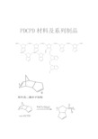
PDCPD材料及系列制品企业简介DCPD材料简介双环戊二烯(简称DCPD),又称二聚环戊二烯,有内型与外型两种异构体,是一种广泛应用的新型塑料材料。
化学式为C10H12,分子量为132.204,相对密度0.979,沸点132℃(分解),熔点32℃,蒸气压1.4mmHg/20℃,凝固点31.5℃,闪点32.22℃,自然点680℃。
溶于醇;常温下为无色晶体,有类似樟脑的气味。
DCPD是一种新型的材料,它的物理指标很优秀,特别是弯曲模量和高抗冲表现很优异。
与普通塑料相比,它的物理性能远优于普通塑料。
DCPD不但易加工还可以制造复杂美观的造型,并具有良好的刚性和强度。
同时,DCPD是一种无污染的材料,废弃产品易处理,不会产生白色垃圾。
鉴于以上优点使DCPD材料在汽车,白色家电,工程建筑,医疗,电气等领域得到了广泛认可和应用。
DCPD-RIM成型工艺简介DCPD-RIM成型,是以双环戊二烯(DCPD)为主要材料,采用两种料液同时注入到模具内,两种料液在反应中不断充满模具。
在极短的时间内生产出大型或复杂形状的热固性交联型聚双环戊二烯(PDCPD)树脂制品。
此工艺与其它模压工艺相比不需要高温高压,更有利于环境的保护。
反应注射成型聚双环戊二烯(PDCPD-RIM)是一种兼具高抗冲和高弯曲模量双重特性的工程材料。
适宜做汽车零部件,体育器材,医疗器械,家电及娱乐设施等。
DCPD-RIM工艺具体原理如下图所示:采用DCPD-RIM成型的PDCPD制品具有的物理特性和电器特性可以广泛代替工程塑料,玻璃钢等原材料,不但可以生产小零件还可以制造大型的复杂的设备装饰件和外覆盖件。
DCPD-RIM成型品的物理特性与其他塑料制品的比较值如下图所示DCPD-RIM的成型品电性能特性如下图所示:DCPD-RIM特点和设计选择DCPD-RIM技术是三液注入技术。
利用三液注入技术,将增强材料分散在液体C中并与A与B在混合头中混合后注入模腔能制成具有高刚性和低线性膨胀系数的产品;其刚性是传统材料的2倍而线性膨胀系数只有传统材料的一半。
误码测试仪使用说明书
二.主要功能
1、 可对线路、设备不间断连续监测 2、 具有强大的误码测试功能,可对 2M 以内各档速率进行测试 N×64k
(N=1~32) 3、 可以测出实际通信速率,并显示其速率结果。 4、 可人为插入误码,检测实际数据传输效果及正确性。 5、 可以和国外测试仪对测。 6、 有背光功能,既能在昏暗的环境下进行测试。 7、 有数据线连通状态指示和同步丢失状态指示,为线路连接及测试提供
CMR-2048V
误码测试仪
使 用 说 明 书
※注 意
本手册任何部分不得复印,翻制或以任何形式在网络中发送,除非得到本公 司的书面许可。本说明书所提及的商标所有权由各商标持有人所有。 本公司有权随时更改产品性能及本说明书而不事先通知客户。 对于以任何形式修改产品及本说明书而造成的产品功能不能实现或对其他
10.启/停:按一次为启,开始测试,再按一次为停
六.测试举例
测试256K传输设备
第一步。先选择下列任一种测试方式 (1).两用户端远程对测
测试仪
传输设备 测试仪
如图方式连接后,两端测试仪会自动对发、收测试数据。根据显示的数据, 得出通信线路质量结果。此时两测试仪的测试码形一定要相间。
(2).两端用户远端环测
4.确定测试码型 按翻屏键、再按选择键、再按 选定测试内容 Patt:63、511、2047( 215-1 )、 MARK、SPACE、ALT
(MARK=1,SPACE=0,ALT=0101)
5.确定测试速率
按
键到
BitRate:N×64k(N=1-32) (当 DTE 方式时不用选速率)
DENON DCD-1500AE 操作说明书

装入和取出碟片时,请避免接触碟片的表面。
小心请勿在信号面(发 出彩虹色光的一面)上 留下指纹。
清洁碟片
· 碟片上的指纹或污垢可能会降低声音和图像质量或导致播 放停顿。请擦去指纹或污垢。
耳机插孔(PHONES) · 如果是私人聆听,您可以将(市售的)耳机连接至此插 孔。通过耳机聆听时,请勿将音量调得过高。
播放/暂停键( ) · 按该键开始播放碟片。 · 如果在碟片匣打开时按该键,碟片匣将关闭并开始播 放。 · 按该键暂时停止播放。
碟片匣 · 在此处装入碟片。( 第10页) · 按碟片匣打开/关闭键打开和关闭碟片匣。 · 通过按播放/暂停键也可以关闭碟片匣。
目录
序言 附件............................................... 3 处理注意事项
碟片............................................. 4 手持碟片......................................... 4 清洁碟片......................................... 4 碟片处理注意事项................................. 4 安装电池........................................... 5 遥控器的操作范围................................... 5 部件名称和功能 前面板........................................... 6 后面板........................................... 6 显示器........................................... 7 遥控器........................................... 8
- 1、下载文档前请自行甄别文档内容的完整性,平台不提供额外的编辑、内容补充、找答案等附加服务。
- 2、"仅部分预览"的文档,不可在线预览部分如存在完整性等问题,可反馈申请退款(可完整预览的文档不适用该条件!)。
- 3、如文档侵犯您的权益,请联系客服反馈,我们会尽快为您处理(人工客服工作时间:9:00-18:30)。
PDCPD材料及系列制品
企业简介
DCPD材料简介
双环戊二烯(简称DCPD),又称二聚环戊二烯,有内型与外型两种异构体,是一种广泛应用的新型塑料材料。
化学式为
C10H12,分子量为132.204,相对密度0.979,沸点132℃(分
解),熔点32℃,蒸气压1.4mmHg/20℃,凝固点31.5℃,闪点
32.22℃,自然点680℃。
溶于醇;常温下为无色晶体,有类似樟脑
的气味。
DCPD是一种新型的材料,它的物理指标很优秀,特别是
弯曲模量和高抗冲表现很优异。
与普通塑料相比,它的物理性能远
优于普通塑料。
DCPD不但易加工还可以制造复杂美观的造型,并具
有良好的刚性和强度。
同时,DCPD是一种无污染的材料,废弃产品
易处理,不会产生白色垃圾。
鉴于以上优点使DCPD材料在汽车,白色家电,工程建筑,医疗,电气等领域得到了广泛认可和应用。
DCPD-RIM成型工艺简介
DCPD-RIM成型,是以双环戊二烯(DCPD)为主要材料,采用两
种料液同时注入到模具内,两种料液在反应中不断充满模具。
在极
短的时间内生产出大型或复杂形状的热固性交联型聚双环戊二烯(PDCPD)树脂制品。
此工艺与其它模压工艺相比不需要高温高压,更有利于环境的保护。
反应注射成型聚双环戊二烯(PDCPD-RIM)是一种兼具高抗冲和高弯曲模量双重特性的工程材料。
适宜做汽车零部件,体育器材,
医疗器械,家电及娱乐设施等。
DCPD-RIM工艺具体原理如下图所示:
采用DCPD-RIM成型的PDCPD制品具有的物理特性和电器特性可以广泛代替工程塑料,玻璃钢等原材料,不但可以生产小零件还可以制造大型的复杂的设备装饰件和外覆盖件。
DCPD-RIM成型品的物理特性与其他塑料制品的比较值如下图所示
DCPD-RIM的成型品电性能特性如下图所示:
DCPD-RIM特点和设计选择
DCPD-RIM技术是三液注入技术。
利用三液注入技术,将增强材料分散在液体C中并与A与B在混合头中混合后注入模腔能制成具有高刚性和低线性膨胀系数的产品;其刚性是传统材料的2倍而线性膨胀系数只有传统材料的一半。
同时,除了可喷塑,上漆,电镀外还
可以生产出高刚性、阻燃以及染色的产品。
三液成型工艺原理图如下:
DCPD-RIM应用产品
车辆领域的应用
保险杠,挡泥板,导流罩,翼子板,底保护壳,电瓶罩等。
工程机械设备领域
外覆盖件,门体,通风格栅,围板,罩盖,顶棚等。
体育器械领域
医疗器械,自动售货机,游戏机,摩托艇等外壳件
化工防腐领域
化工管道,容器,格栅,阀门,过滤板,高温防腐风机等。
电器元件壳体零部件,柜体及家电壳体及消防领域
电器元件外壳,电控柜,网络机柜,洗衣机壳体等。
连接件领域
罩盖,堵头,连接件等。
家具生活领域
材料性能测试结果耐候性测试
1,风蚀照射实验
2,风蚀照射实验
3,风蚀照射实验
材料加热实验1,加热实验
2,加热实验
3,加热实验
扭曲变形实验
扭曲负荷下的耐气候扭曲实验
疲劳测试
双夹持实验法
反复扭曲疲劳测试
反复扭曲疲劳测试参数
结果
从反复扭曲疲劳曲线的结果可以推测出静止疲劳极限大约为最大扭曲强度的1/4左右。
因此,强度设计的容许应力度就必须按不超过最大扭曲强度的1/4(1.8kgf/mm2)来设计。
拉伸蠕变测试
1,目的
对一定负荷下的变形加剧(蠕变特性)进行测定。
然后测量出影响长期承受载荷状态下使用时(特别在高温下)的蠕变破坏应力。
2,实验方法:
依据JISK7115标准。
(拉伸蠕变试验法)
试验机:高温蠕变试验机(DJK公司生产)
实验片:ASTM1号哑铃(平行部分宽13mm,卡盘间距113mm)
试验条件:①试验温度:23,60,80℃。
②试验载荷:破坏应力的20,40,60%。
③试验时间:1.000小时以内
3,结果:
参照下图所示
23℃时,即使有60%的破坏应力载荷,用1.000个小时也不会出现破坏。
60℃时,在60%的破坏应力载荷下,700小时发生破坏。
20~40%荷重的情况下,用1.000个小时,约有0.5~4%发生蠕变变形。
80%的情况下,破坏应力为40%时,500个小时产生破坏。
20%载荷,1.000个小时的情况下,0.6%左右发生蠕变变形。
耐腐蚀测试
1,药品浸泡导致的重量变化
实验方法:
依据JISK7114标准。
⑴实验片:50mm×50mm,厚4mm(端面未处理)
⑵浸泡药品:10%硫酸,40%氢氧化钠
⑶浸泡温度:80±3℃
⑷浸泡时间:3,7,15,30日
结果:用10%硫酸及40%氢氧化钠,30日后其重量变化可以认为不影响使用。
药品浸泡导致的扭曲特性
实验方法:
依据JIS K7070标准。
⑴实验片:(浸泡实验)110mm×90mm,厚4mm(端面未处理),(扭曲实
验)110mm×90mm,厚4mm
⑵扭曲试验机:万能精密材料试验机AGS-500(依据JIS K7203标准)
⑶浸泡药品:10%硫酸,40%氢氧化钠
⑷浸泡温度:80±3℃
⑸浸泡时间:3,7,15,30日
结果:即使使用10%硫酸及40%氢氧化钠,其扭曲强度,扭曲弹性率未见逐日下降,可以说完全能满足结构设计。
环保措施及循环再生
一, PDCPD燃烧时产生的二噁英,氧化氮和盐酸气体仅相当于PP的水平。
产品不含RoHS标准下的六中特定的有害物质。
产品不含任何导致内分泌紊乱的化学物质。
二,发热值为9990Kcal/kg(煤油发热值10500Kcal/kg),可用于水泥窑燃料。
三,PDCPD粉碎后可以作为热塑性塑料(如:PP,PE等)的填料,生产窨井盖,地下电缆保护箱等热压成型制品。
