SanDisk SD Card产品手册之四SD卡协议描述续二
(完整版)SD卡协议-中文

(完整版)SD卡协议-中文一概述1. SD总线模式下CLK:时钟信号CMD:双向命令和响应信号DAT0-3:双向数据信号VDD,VSS:电源和地信号SD模式下允许有一个主机, 多个从机(即多个卡), 主机可以给从机分别地址. 主机发命令有些命令是发送给指定的从机,有些命令可以以广播形式发送.SD模式下可以选择总线宽度, 即选用几根DAT信号线, 可以在主机初始化后设置.2. SD总线协议SD模式下的命令和数据流都有一个开始位和结束位.>命令: 是在CMD上传输的用于启动一个操作的比特流. 由主机发往从机, 可以是点对点也可以是广播的.>响应: 是在CMD上传输的用于之前命令回答的比特流. 由从机发往主机.>数据: 是在DAT上传输的比特流, 双向传输.无响应模式无数据模式多块读操作模式多块写操作模式命令格式响应格式数据格式SD卡上电后会自动初始化,通过给卡发送CMD0也可以复位卡.二.SD卡命令描述.1.广播命令:给所有卡都发送, 某些命令需要响应.2.点对点命令给指定地址的卡发送, 需要响应.SD卡系统有两种工作模式:1.卡识别模式.主机上电复位后即处于此模式,它会在总线上等待卡. 卡复位后也处于此模式, 直到SEND_RCA(CMD3)命令到来.2.数据传输模式.卡收到SEND_RCA(CMD3)命令后即进入此模式. 主机识别到卡后也进入此模式.卡状态和工作模式对照表1.卡识别模式.此模式下主机复位总线所有的卡, 验证工作电压, 询问卡的地址. 这个模式下所有数据的传输都是只通过CMD线来完成.1)卡的复位.当卡上电或收到GO_IDLE_STATE (CMD0)命令后, 卡即进入Idle State状态. 此时卡将其RCA设为0, 相关寄存器设为传输稳定的最优模式.2)工作电压验证每个卡的最高和最低工作电压存储在OCR. 只有当电压比配时, CID和CSD的数据才能正常传输给主机.SD_SEND_OP_COND (ACMD41)命令用来判断卡的工作电压是否符合, 如果不符合的话, 卡应该放弃总线操作, 进入Inactive State状态. 在发送SD_SEND_OP_COND (ACMD41)命令前记得要首先发送APP_CMD (CMD55).卡的状态变换图.ACMD41命令响应中的BUSY位也用于卡表示其还没准备好, 主机此时应重发ACMD41命令,直到卡准备好.主机在这个阶段的ACMD41中不允许改变工作电压, 如果确实想改变的话, 应该先发送CMD0, 然后再发送改变后的ACMD41.GO_INACTIVE_STATE (CMD15)命令用于使指定地址的卡进入Inactive State模式.3)卡识别过程.ALL_SEND_CID (CMD2)命令用于获取卡的CID信息, 如果卡处于Ready State, 它就会在CMD线上传送它的CID信息, 然后进入Identification State模式. 紧接着发送CMD3 (SEND_RELATIVE_ADDR)命令, 用于设置卡新的地址. 卡收到新的地址后进入Stand-by State 模式.2.数据传输模式.数据传输模式下卡的状态转变图进入数据传输模式后, 主机先不停的发送SEND_CSD (CMD9)命令获取卡的CSD信息. SET_DSR (CMD4)用于设置卡的DSR寄存器, 包括数据总线宽度, 总线上卡的数目, 总线频率, 当设置成功后, 卡的工作频率也随之改变. 此步操作是可选的.CMD7命令用于使指定地址的卡进入传输模式, 任何指定时刻只能有一个卡处于传输模式.传输模式下所有的数据传输都是点对点的, 并且所有有地址的命令都需要有响应..所有读命令都可以由CMD12命令停止,之后卡进入Transfer State. 读命令包括单块读(CMD17), 多块读(CMD18), 发送写保护(CMD30), 发送scr(ACMD51)和读模式一般命令(CMD56)..所有写命令都可以由CMD12命令停止. 写命令包括单块读(CMD24), 多块读(CMD25), 写CID(CMD26), 写CSD(CMD27),锁和解锁命令(CMD42)和写模式一般命令(CMD56)..当写命令传输完成后, 卡进入Programming State(传输成功)或Transfer State(传输失败).如果一个卡写操作被停止,但其前面数据的CRC和块长度正确, 数据还是会被写入..卡要提供写缓冲, 如果写缓冲已满并且卡处于Programming State, DAT0保持低BUSY. .写CID,CSD, 写保护, 擦除命令没有缓冲, 当这些命令没完时, 不应发送其他的数据传输命令..参数设置命令在卡被编程时是不允许发送的, 这些命令包括设置块长度(CMD16), 擦除块起始(CMD32)和擦除块结束(CMD33)..当卡正编程时读命令是禁止的..用CMD7使另一个卡进入Transfer State不会终止当前卡的编程和擦除, 当前卡会进入Disconnect State并且释放DAT线.. Disconnect State模式的卡可通过CMD7重新被选中,此时卡进入Programming State 并且使能busy信号.. CMD0或CMD15会终止卡的编程操作, 造成数据混乱, 此操作应禁止.1)总线宽度选择命令ACMD6命令用于选择总线宽度, 此命令只有在Transfer State有效. 应在CMD7命令后使用.2)块读命令块是数据传输的最小单位, 在CSD (READ_BL_LEN)中定义, SD卡为固定的512B.每个块传输的后面都跟着一个CRC校验. CMD17(READ_SINGLE_BLOCK)用于传输单个块,传输完之后,卡进入Transfer State. CMD18 (READ_MULTIPLE_BLOCK)用于多个块的传输,直到收到一个CMD12命令.3)块写命令与块读命令类似, 每个块传输的后面都跟着一个CRC校验.卡写数据时会进行CRC校验.多块写比重复的单块写更能提高效率.如果CSD中的WRITE_BLK_MISALIGN没设置, 并且发送的数据不是块对齐的, 卡会设置状态寄存器中的ADDRESS_ERROR位,并且进入Receive-data-State状态等待停止命令.此时写操作也会停止, 并且卡会设置其的WP_VIOLATION位.如果写缓冲满的话, 卡会停止接受WRITE_BLOCK命令. 此时主机应发送SEND_STATUS (CMD13)命令, 卡返回数据的READY_FOR_DATA位标志卡是否准备好接受新的数据.在多块写操作中通过事先发送ACMD23命令可提高写速度. ACMD23用于定义接下来要写数据的块的数目. 每次多块写操作后, 这个值又被设为默认的1.ACMD22会使卡返回写成功的块数目.4)擦除命令擦除命令的顺序是: ERASE_WR_BLK_START(CMD32),ERASE_WR_BLK_END(CMD33)an d ERASE (CMD38).如果(CMD38或(CMD32, 33)接收到出错信息, 卡会设置状态寄存器中的ERASE_SEQ_ERROR 位并且重新等待新的命令时序.如果接收到时序错误命令, 卡会设置其ERASE_RESET位并且重新等待新的命令时序.5)写保护管理三种机制:-.写保护物理开关-.卡内部写保护通过设置CSD中的WP_GRP_ENABLE位和WP_GRP_SIZE位, SET_WRITE_PROT和CLR_WRITE_PROT命令用来设置和清除保护机制.-. 密码保护.三. 时钟控制如果主机要发送1K的数据, 但是主机缓冲区只有512B, 那么主机可以在发送完前512B 后, 可以先停止时钟, 然后把后512B填充入缓冲区, 再启动时钟, 这样卡并不会检测要两次发送之间的间隔, 认为其是一次完整的数据发送过程.四 CRC校验1.CRC7CRC7用于所有的命令, 除R3以外的响应, 以及CID和CSD寄存器.2.CRC16CRC16用于数据块的校验五. 错误类型.1. CRC错误和命令非法错误命令的CRC校验出错, 卡设置其状态寄存器的COM_CRC_ERROR 位.非法命令错误, 卡设置其状态寄存器的ILLEGAL_COMMAND位.非法命令包括:不支持的命令,未定义的命令以及当前状态不支持的命令.2. 读,写和擦除超时.卡应该在指定的时间内完成一个命令或返回移动的错误信息. 如果在指定的超时时间内主机收不到响应, 应认为卡停止工作, 应重新复位卡.六命令1. 命令类型:- bc不需要响应的广播命令.- bcr需要响应的广播命令. 每个卡都会独立的接收命令和发送响应.- ac点对点命令, DAT线上没数据- adtc点对点命令, DAT线上有数据所有命令均遵守上图中的格式, 总共48位. 首先是1个起始位0,接着是1个方向位(主机发送位1), 6个命令位( 0-63 ), 32位参数(有些命令需要), CRC7位校验, 1个停止位.2.卡命令根据不同的类型分成了不同的Class, 见下表,其中Class0,2,4,5,8是每个卡都必须支持的命令, 不同的卡所支持的命令保存在CSD中.3.命令详细描述1)基本命令Class02)读命令Class23)写命令Class43)擦除命令Class54)应用特定命令Class8下表中的所有命令使用前都应先跟一个APP_CMD(CMD55)命令七. 卡状态转换表八. 应答.所有的应答都是通过CMD发送,不同的应答长度可能不同.总共有四种类型的应答.1. R1: 长度位48位.注意每个块传输完成后有一个BUSY位.2.R1b:与R1类似, 只是将BUSY位加入响应中.3.R2(CID CSD寄存器) : 长度为136位, CID为CMD2和CMD10的应答, CSD为CMD9的应答.4.R3(OCR寄存器):长度位48位. 作为ACMD41的应答.5.R6(RCA地址应答):长度为48位九. 卡的状态SD卡支持两种状态:-卡状态:与MMC卡兼容.-SD卡状态:扩充到了512位.1.卡状态:R1应答包含一个32位的卡状态.见下表.其中Type中的含义为:E:错误位. S:状态位. R:根据命令在响应中设置.X:根据在命令执行期间设置, 必须再次读此位才能获得命令执行后的情况.Clear Condition:A: 与卡的当前状态有关B: 总是与命令有关,无效的命令会清除此位.C: 通过读此位来清除下表指明了哪些命令可能使哪些位产生变化2.SD卡状态:这些位通过DAT线传输, 并伴有CRC16校验. 其是作为ACMD13的应答.十. 卡存储器形式.-块:块是基本读写命令的单位,它可以是固定的或可变的. 关于块的大小以及其是否可变性存储在CSD中.-扇区:扇区是擦除命令的单位, 它是固定的值,保存在CSD中.十一. 时序图时序图中字母含义:1.命令和应答1)卡识别和卡工作电压确认模式:CMD2,ACMD412)地址分配模式:CMD33)数据传输模式:4)命令结束->下一个命令:5)两个命令直接1)单块读:CMD172)多块读:读过程时序.停止命令时序3.数据写1)单块写:注意Busy信号.2)多块写:多块写命令时序停止命令时序卡主动停止时的时序。
sd卡总线协议

编号:_______________本资料为word版本,可以直接编辑和打印,感谢您的下载sd卡总线协议甲方:___________________乙方:___________________日期:___________________sd卡总线协议篇一:sd卡接口的完整规范sd卡接口规范的完整翻译特性:◎容虽:32mb/64mb/128mb/256mb/512mb/1gbyte ◎兼容规范版本1.01 ◎卡上错误校正◎支持cpRm◎两个可选的通信协议:sd模式和spi模式◎可变时钟频率0— 25mh应通信电压范围:2.0-3.6V 工作电压范围:2.0-3.6V◎低电压消耗:自动断电及自动睡醒,智能电源管理◎ 无需额外编程电压◎卡片带电插拔保护◎正向兼容mmc^◎高速串行接口带随即存取----- 支持双通道闪存交叉存取----- 快写技术:一个低成本的方案,能够超高速闪存访问和高可靠数据存储---- 最大读写速率:10mbyte/s◎最大10个堆叠的卡(20mhz,Vcc=2.7-3.6V) ◎数据寿命:10万次编程/擦除◎ ce和Fcc认证◎ pip封装技术◎尺寸:24mm® x 32mn#x 1.44mm厚说明:本sd卡高度集成闪存,具备串行和随机存取能力。
可以通过专用优化速度的串行接口访问,数据传输可靠。
接口允许几个卡垛叠,通过他们的外部连接。
接口完全符合最新的消费者标准,叫做sd卡系统标准,由sd卡系统规范定义。
sd卡系统是一个新的大容虽存储系统,基于半导体技术的变革。
它的出现,提供了一个便宜的、结实的卡片式的存储媒介,为了消费多媒体应用。
sd 卡可以设计出便宜的播放器和驱动器而没有可移动的部分。
一个低耗电和广供电电压的可以满足移动电话、电池应用比如音乐播放器、个人管理器、掌上电脑、电子书、电子白科全书、电子词典等等。
使用非常有效的数据压缩比如mpeg, sd卡可以提供足够的容虽来应付多媒体数据。
SD卡使用手册
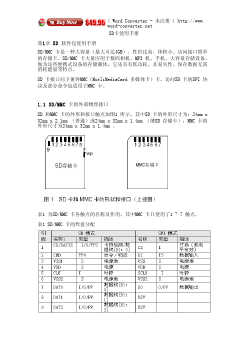
SD卡使用手册第1章 SD软件包使用手册SD/MMC 卡是一种大容量(最大可达4GB)、性价比高、体积帏、访问接口简单的存储卡。
SD/MMC 卡大量应用于数码相机、MP3 机、手机、大容量存储设备,做为这些便携式设备的存储载体,它还具有低功耗、非易失性、保存数据无需消耗能量等特点。
SD 卡接口向下兼容MMC(MutliMediaCard 多媒体卡)卡,访问SD 卡的SPI 协议及部分命令也适用于MMC 卡。
1.1 SD/MMC卡的外部物理接口SD 和MMC 卡的外形和接口触点如图1 所示。
其中SD 卡的外形帺寸为:24mm x 32mm x 2.1mm (普通)或24mm x 32mm x 1.4mm (薄SD 存储卡),MMC 卡的外形帺寸为24mm x 32mm x 1.4mm 。
表1 为SD/MMC 卡各触点的名称及作用,其中MMC 卡只使用了1 ~ 7 触点。
表1 SD/MMC 卡的焊盘分配滨:1. S:电源;I:输入;O:推挽输出;PP:推挽I/O。
2. 扩幕的DAT 线(DAT1 ~ DAT3 )在上电后处于输入状态。
它们在执行SET_BUS_WIDTH 命令后作为DAT 线操作。
当不使用DAT1 ~ DAT3 线时,主机应使自己的DAT1~DAT3 线处于输入模式。
这样定义是为了与MMC 卡保持兼容。
3. 上电后,这条线为带50KΩ上拉电阻的输入线(可以用于检测卡是否存在或选择SPI 模式)。
用户可以在正常的数据传输中用SET_CLR_CARD_DETECT(ACMD42 )命令断开上拉电阻的连接。
MMC 卡的该引脚在SD 模式下为保留引脚,在SD 模式下无任何作用。
4. MMC 卡在SD 模式下为:I/O/PP/OD。
5. MMC 卡在SPI 模式下为:I/PP。
由表1 可见,SD 卡和MMC 卡在不同的通信模式下,各引脚的功能也不相同。
这里的通信模式是指微控制器(主机)访问卡时使用的通信协议,分为两种:SD 模式及SPI 模式。
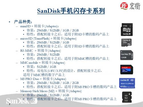
SanDisk手机闪存卡简介
3
MiniSD
Nokia---6270/N73/N71 MOTO----E60i/E60g /E2 多普达---565/566/575/585/58 6 飞利浦---768/960/680 夏新----M639/ E600 联想---I750/I921/I902/V920 /I950 LG----G262 明基----E61 /Qube 波导----D610 康佳-----D161/ S901/D261/D162 金立----K8/N6
2m2大小只有msproduo13产品介绍手机存储卡手机适配表microsdtransflashminisdmmcmobilemsproduonokia3250613155006125motoa1200a780l7v3ie398v360a732samsungd608x808x708x818i308d518d828e778e908i858联想v707v517lgg912g832多普达710夏新a668a665a865a868e850tclm360d866d868d308v9d668d628d638e787766782c338c328c318d368v5明基cl71s88波导d650d700康佳s905d163m960金立v8s30v99nokia6270n73n71motoe60ie60ge2多普达565566575585586飞利浦768960680sd多普达818828830飞利浦968tcle777nokian70n723230qd93007610668166706230isamsungd728msproduo索爱k750cw800cw700cmsmicrom2索爱z530ck790cw300cw710cz710cz550cm608c3夏新m639e600联想i750i921i902v920i950lgg262明基e61qube波导d610康佳d161s901d261d162金立k8n6明基p50
SD2.0协议标准完整版[1-6章中文翻译]
![SD2.0协议标准完整版[1-6章中文翻译]](https://img.taocdn.com/s3/m/6963f0cabb4cf7ec4afed05a.png)
3.5.1 SD 总线
图 3-2 SD 卡总线拓扑 SD 总线包含下面的信号: CLK: 时钟信号 CMD: 双向命令/响应信号 DAT0-DAT3: 双向数据信号 Vdd,Vss1,Vss2: 电源和地信号 SD 卡总线有一个主(应用),多个从(卡),同步的星型拓扑结构(图 3-2)。时钟,电源和 地信号是所有卡都有的。命令(CMD)和数据(DAT0-3)信号是根据每张卡的,提供连续地点对 点连接到所有卡。 在初始化时, 处理命令会单独发送到每个卡, 允许应用程序检测卡以及分配逻辑地址给 物理卡槽。数据总是单独发送(接收)到(从)每张卡。但是,为了简化卡的堆栈操作,在初始 化过程结束后,所有的命令都是同时发送到所有卡。地址信息包含在命令包中。 SD 总线允许数据线的动态配置。上电后,SD 卡默认只使用 DAT0 来传输数据。初始化之 后, 主机可以改变总线宽度(使用的数据线数目)。 这个功能允许硬件成本和系统性能之间的 简单交换。
注意:当 DAT1-DAT3 没有使用的时候,相关的主机 DAT 先应该被设置为输入模式。SDIO 卡 DAT1 和 DAT2 用于信令。
3.5.2 SPI 总线
SD 卡的 SPI 兼容通信模式是用来同 SPI 信道通信,主要是用在市场是哪个的各种微处 理器。模式选择是在上电后的第一次 reset 命令期间,并且只要不断电就不能改变。SPI 标 准只是定义了物理连接,没有完成数据传输协议。SD 卡的 SPI 实现使用了 SD 模式相同的命 令。从应用的角度来说,SPI 模式的优点是使用现成主机的能力,从而减小设计压力。相对 于使能宽总线选项的 SD 卡来说,缺点是性能的损失。SD 卡 SPI 接口同市场上现有的 SPI 主 机兼容。同其他 SPI 设备一样,SD 卡的 SPI 信道有以下 4 个信号: CS: 主机到卡的片选(chip select)信号 CLK: 主机到卡的时钟信号 DataIn: 主机到卡的数据信号 DataOut: 卡到主机的数据信号 另一个 SPI 的通用特点是字节传输,这也是卡的实现。所有的数据都是字节(8 bit)的 整数倍,并且直接总是对齐 CS 信号。
sd卡协议(中文)
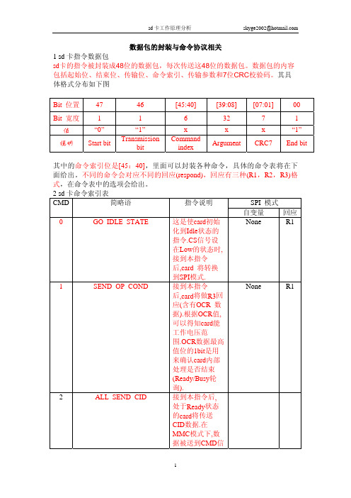
数据包的封装与命令协议相关1 sd 卡指令数据包sd 卡的指令被封装成48位的数据包,每次传送这48位的数据包。
数据包的内容包括起始位、结束位、传输位、命令索引、传输参数和7位CRC 校验码。
其具体格式分布如下图 Bit 位置 47 46 [45:40] [39:08] [07:01] 00 Bit 宽度 1 1 6 32 7 1 值 “0” “1” x x x “1”说明Start bit Transmission bit CommandindexArgument CRC7 End bit其中的命令索引位是[45:40],里面可以封装各种命令,具体的命令表将在下面给出。
不同的命令会对应不同的回应(respond),回应有三种(R1,R2,R3)格式,在命令表中的选项会给出。
2 sd 卡命令索引表 CMD 简略语 指令说明 SPI 模式自变量 回应0 GO_IDLE_STATE 这是使card 初始化到Idle 状态的指令.CS 信号设在Low 的状态时,接到本指令后,card 将转换到SPI 模式.None R11 SEND_OP_COND 接到本指令后,card 将做R3回应(含有OCR 数据).根据OCR 值,可以得知card 能工作电压范围.OCR 数据最高值位的1bit 是用来确认card 内部处理是否结束(Ready/Busy 轮询).None R12 ALL_SEND_CID 接到本指令后, 处于Ready 状态的card 将传送CID 数据.在MMC 模式下,数据被送到CMD 信号,在CID数据的每1bit传送后,CMD信号状态将与该card内部状态相比较,如果不一致,將中止数据传送,card返回到Ready状态.如果相一致,该card 将认为已被选中,然后转换到Identification 状态.3 SET_RELATIVE_ADDR 本指令会为已转换到Identification状态的card分配一个相对card地址(RCA).当RCA分配后,card将转换到Stand-by 状态,对以后的CMD2和CMD3不回应.4 NOP 这是用来设定DSR(DriveState寄存器)的指令,但是本car不支持DSR.7 SELECT/DESELECT_CARD本指令是用来选择一张card,让它在Stand-by状态和Transfer状态之间转换的指令.如果给card设定已分配到的RCA地址,card将从Stand-by状态转换到Transfer状态,并将回应以后的读取指令及其他指令.如果给card设定RCA以外的地址,card将转换到Stand-by状态。
sd卡协议分析

sdMmc目录第一章 SD卡系统概念 3§1.1 SD卡概述 3§1.2 SD卡的系统特征 3§1.3 SD卡的系统概念 4§1.4 SD卡的总线传输 6§1.5 SD卡的引脚 10§1.6 SD卡主要寄存器介绍 12§1.7 SD卡子系统结构 14第二章 SD卡初始化及状态转换 16§2.1SD卡状态及初始化过程 16§2.2SD卡数据传输过程 181.SD卡基础1.SD卡概述SD卡由日本松下、东芝及美国SanDisk公司于1999年8月共同开发研制,同时三个公司联合成立了SD协会,并制定SD卡相关的协议标准。
SD卡协议主要包括物理层协议、SD卡控制器设计手册、SDIO卡手册三部分。
其中SDIO指的是安全数字输入输出卡(Secure Digital Input and Output Card),是在SD标准上定义了一种外设接口,通过SD的I/O接脚来连接外围设备,并且通过SD上的 I/O数据接位与这些外围设备进行数据传输。
相关的一些设备为:GPS、相机、Wi-Fi、调频广播、条形码读卡器、蓝牙等。
SDIO本质上是一种接口,通过该接口可以连接一些其他功能的设备而非仅仅是存储设备。
1.2 SD卡的系统特征(SD物理层协议v2.0)∙针对移动和固定应用;∙存储容量:标准容量SD存储卡:最高2G高容量SD存储卡:2G以上(在该规范版本中,最高32G)∙电压范围:高电压SD存储卡—操作电压范围:2.7~3.6V双电压SD存储卡—操作电压范围:低电压范围(T.B.D)和2.7~3.6V∙分为只读卡和读/写卡;∙默认模式:时钟频率可在0~25MHz间变化,高达12.5MB/s 的接口速度(使用4条并行数据线) ;∙高速模式:时钟频率可在0~50MHz间变化,高达25MB/s 的接口速度(使用4条并行数据线) ;∙支持高速,电子商务和将来功能的转换功能命令;∙存储域错误纠正;∙读操作期间移去卡,内容不损坏;∙内容保护机制—符合SDMI标准的最高安全性;∙卡的密码保护(CMD42 - LOCK_UNLOCK);∙机械开关的写保护特性;∙内嵌的写保护特性(永久或暂时) ;∙卡检测(插入/移去) ;∙应用特定命令;∙舒适的擦除机制∙通信通道协议属性;∙SD存储卡外形尺寸:标准尺寸SD存储卡(32*24*2.1mm) 。
tf卡通信协议

竭诚为您提供优质文档/双击可除tf卡通信协议篇一:sd卡和tF卡简介sd卡和tF卡简介tF卡全名:transFlash,原名microsdcard。
由摩托罗拉与sandisk共同研发,在20xx年推出。
是一种超小型卡(11*15*1mm),约为sd卡的1/4,可以算目前最小的储存卡了。
tF卡可经sd卡转换器后,当sd卡使用。
利用适配器可以在使用sd作为存储介质的设备上使用。
transFlash主要是为照相手机拍摄大幅图像以及能够下载较大的视频片段而开发研制的。
transFlash卡可以用来储存个人数据,例如数字照片、mp3、游戏及用于手机的应用和个人数据等,还内设置版权保护管理系统,让下载的音乐、影像及游戏受保护;未来推出的新型transFlash还备有加密功能,保护个人数据、财政纪录及健康医疗文件。
体积小巧的transFlash让制造商无须顾虑电话体积即可采用此设计,而另一项弹性运用是可以让供货商在交货前随时按客户不同需求做替换,这个优点是嵌入式闪存所没有的。
tF卡引脚定义:tF卡(sd模式):1-data2,2-data3,3-cmd,4-vdd,5-clk,6-vss,7-data0,8-d ata1tF卡(spi模式):1-rsv,2-cs,3-di,4-vdd,5-sclk,6-vss,7-do,8-rsv sd卡(securedigitalmemorycard)安全数码卡,是一种基于半导体快闪记忆器的新一代记忆设备,它被广泛地于便携式装置上使用,例如数码相机、个人数码助理(外语缩写pda)和多媒体播放器等。
sd卡是一种基于半导体闪存工艺的存储卡,1999年由日本松下主导概念,参与者东芝和美国sandisk公司进行实质研发而完成。
2000年这几家公司发起成立了sd协会(securedigitalassociation简称sda),阵容强大,吸引了大量厂商参加。
其中包括ibm,microsoft,motorola,nec、samsung等。
SD卡解读报告2

[SD卡解读报告2]目录一、SD存储卡传输速度与什么有关 (3)二、SD卡NAND Flash芯片来源 (4)三、SD卡预装内容的市场前景 (4)四、支持存储卡扩展的MP3/MP4播放器情况 (6)一、SD存储卡传输速度与什么有关SD存储卡是一种没有太复杂架构的产品,从结构上讲,目前几乎所有的存储卡都采用NAND Flash芯片+控制芯片的方式制造。
NAND Flash芯片共有2种不同内部结构的规格分支,分别是SLC和MLC。
SLC全称单层式储存,MLC全称多层式储存。
综合而言,前者容量小,速度快,寿命长。
后者容量大,速度慢,寿命短。
MLC架构技术上更加先进,同时又具备成本和良率等优势。
MLC NAND Flash自身技术的原因,只有靠控制芯片的高效能才能支持和弥补其速度上的缺点,支持MLC制程的控制芯片需要较严格的标准,以充分发挥NAND Falsh芯片的性能。
目前支持MLC制程的控制芯片技术已经相当完善,SLC可以说已经成为历史。
所有NAND Flash芯片读取、写入或擦除数据都是在闪存控制芯片下完成的,闪存控制芯片的速度决定了闪存里数据的读取、擦除或是重新写入的速度。
SD卡的传输速度是根据控制芯片来决定的,因此SD卡传输速度的快慢与控制芯片有关。
二、SD卡NAND Flash芯片来源白片:按照行内的默认规则就是质量稍好的,闪存容量偏差不大的,因为生产厂家检测容量不够而废弃的Flash芯片黑片:按照行内的默认规则就是质量很差的,闪存容量偏差很大或者明显存在其它质量缺陷的Flash芯片正规片:一个晶圆上有成百上千个芯片单元(die),在晶圆生产好后要经过测试并把不好的部分标记上,不好的芯片单元(die)将被舍弃。
晶圆切割并封装后就是我们看到的带管脚的NAND Flash芯片了,在封装阶段检测不合格的芯片也会被丢弃。
黑芯:大体上有两种,一是指三星、东芝、现代等厂商淘汰下来的残次晶圆。
晶圆的良品率并非100%的,晶圆生产下来都是分等级的,一般可分为99%容量、97%容量、93%容量等。
sandisk TF卡级别

按照 SDA协会阐述的,Class是用来描述最Байду номын сангаас连续传输速度的标记。
CLASS 2是连续传输速度在2M/S以上,
CLASS 4是连续传输速度在4M/S以上,
CLASS 6是连续传输速度在6M/S以上。
CLASS 10是连续传输速度在10M/S以上。
目前最高的是CLASS10理论上来说,CLASS 4只要读写速度不低于4M都是正常的,读卡速度和电脑、系统、卡都有关联,
SDXC的传输速度定义了50MB/s、104MB/s和300MB/s三种.
SD2.0的规范中对于SD卡的性能上分为如下4个等级,不同等级能分别满足不同的应用要求:
Class 0:包括低于Class 2和未标注Speed Class的情况;
Class 2:能满足观看普通MPEG4 MPEG2 的电影、SDTV、数码摄像机拍摄;
Class 4:可以流畅播放高清电视(HDTV),数码相机连拍等需求;
Class 6:满足单反相机连拍和专业设备的使用要求;
Ultra / Extreme /Extreme Pro的速度等级不同,
Ultra 高速卡,二代卡,速度是150X,传输速度在10M/S,五年保
Extreme极速卡,三代卡,速度是200X,传输速度在30M/S,终身固保
SD:
采用FAT16文件系统
SDHC:
High Capacity SD Memory Card,容量2GB-32GB,采用FAT32 文件系统.至少需符合Class 2的速度等级,并且在卡片上必须有SDHC标志和速度等级标志
SDXC:
SD卡基础介绍
安全数码卡
Lenovo Confidential
1 © 2005 Lenovo
目录
SD卡简介 卡简介
SD卡技术 卡技术 SD卡的结构 卡的结构 SD卡的速度 卡的速度 SD卡品牌简介 卡品牌简介
He Hua Phoenix Process Management Review
2005 Lenovo Confidential
He Hua Phoenix Process Management Review
2005 Lenovo Confidential
3 © 2005 Lenovo
SD卡的技术 卡的技术
SD卡在24mm×32mm×2.1mm的体积内结合了SanDisk快闪记忆卡控制与 MLC(Multilevel Cell)技术和Toshiba(东芝)0.16u及0.13u的NAND技术, 通过9针的接口界面与专门的驱动器相连接,不需要额外的电源来保持其上记 忆的信息。而且它是一体化固体介质,没有任何移动部分,所以不用担心机械 运动的损坏 SD卡的技术建是基于 卡的技术建是基于MultiMedia卡(MMC)格式上发展而来,大小和MMC 卡 )格式上发展而来,大小和 卡的技术建是基于 差不多,尺寸为32mm x 24mm x 2.1mm。长宽和 一样, 差不多,尺寸为 。长宽和MMC一样,只是比 一样 只是比MMC厚 厚 0.7mm,以容纳更大容量的存贮单元。SD卡与 卡与MMC卡保持着向上兼容 卡保持着向上兼容, 了0.7mm,以容纳更大容量的存贮单元。SD卡与MMC卡保持着向上兼容, 也就是说, 可以被新的SD设备存取 也就是说,MMC可以被新的 设备存取,兼容性则取决于应用软件,但SD 可以被新的 设备存取,兼容性则取决于应用软件, 卡却不可以被MMC设备存取。( 卡外型采用了与 设备存取。( 卡外型采用了与MMC厚度一样的导轨式 卡却不可以被 设备存取。(SD卡外型采用了与 厚度一样的导轨式 设计,以使SD设备可以适合 设备可以适合MMC)。 设计,以使 设备可以适合 。 SD接口除了保留 接口除了保留MMC的7针外,还在两边加多了 针,作为数据线。采 针外, 接口除了保留 的 针外 还在两边加多了2针 作为数据线。 用了NAND型Flash Memory,基本上和 的一样, 用了 型 ,基本上和SmartMedia的一样,平均数据传输 的一样 率能达到2MB/s。 率能达到 。
SANDISK TF规格书

SanDisk microSDOEM Product ManualRevision 2.0Document No. 80-36-03335March 2010SanDisk CorporationCorporate Headquarters • 601 McCarthy Blvd. • Milpitas, CA 95035 Phone (408) 801-1000 • Fax (408) 801-8657Products, samples and prototypes are subject to update and change for technological and manufacturing purposes.SanDisk® Corporation general policy does not recommend the use of its products in life support applications wherein a failure or malfunction of the product may directly threaten life or injury. Without limitation to the foregoing, SanDisk shall not be liable for any loss, injury or damage caused by use of its products in any of the following applications:∙Special applications such as military related equipment, nuclear reactor control, and aerospace∙Control devices for automotive vehicles, train, ship and traffic equipment∙Safety system for disaster prevention and crime prevention∙Medical-related equipment including medical measurement deviceAccordingly, in any use of SanDisk products in life support systems or other applications where failure could cause damage, injury or loss of life, the products should only be incorporated in systems designed with appropriate redundancy, fault tolerant or back-up features. Per SanDisk Terms and Conditions of Sale, the user of SanDisk products in life support or other such applications assumes all risk of such use and agrees to indemnify, defend and hold harmless SanDisk Corporation and its affiliates against all damages.Security safeguards, by their nature, are capable of circumvention. SanDisk cannot, and does not, guarantee that data will not be accessed by unauthorized persons, and SanDisk disclaims any warranties to that effect to the fullest extent permitted by law.This document and related material is for information use only and is subject to change without prior notice. SanDisk Corporation assumes no responsibility for any errors that may appear in this document or related material, nor for any damages or claims resulting from the furnishing, performance or use of this document or related material. SanDisk Corporation explicitly disclaims any express and implied warranties and indemnities of any kind that may or could be associated with this document and related material, and any user of this document or related material agrees to such disclaimer as a precondition to receipt and usage hereof. EACH USER OF THIS DOCUMENT EXPRESSLY WAIVES ALL GUARANTIES AND WARRANTIES OF ANY KIND ASSOCIATED WITH THIS DOCUMENT AND/OR RELATED MATERIALS, WHETHER EXPRESS OR IMPLIED, INCLUDING WITHOUT LIMITATION, ANY IMPLIED WARRANTY OF MERCHANTABILITY OR FITNESS FOR A PARTICULAR PURPOSE OR INFRINGEMENT, TOGETHER WITH ANY LIABILITY OF SANDISK CORPORATION AND ITS AFFILIATES UNDER ANY CONTRACT, NEGLIGENCE, STRICT LIABILITY OR OTHER LEGAL OR EQUITABLE THEORY FOR LOSS OF USE, REVENUE, OR PROFIT OR OTHER INCIDENTAL, PUNITIVE, INDIRECT, SPECIAL OR CONSEQUENTIAL DAMAGES, INCLUDING WITHOUT LIMITATION PHYSICAL INJURY OR DEATH, PROPERTY DAMAGE, LOST DATA, OR COSTS OF PROCUREMENT OF SUBSTITUTE GOODS, TECHNOLOGY OR SERVICES.No part of this document may be reproduced, transmitted, transcribed, stored in a retrievable manner or translated into any language or computer language, in any form or by any means, electronic, mechanical, magnetic, optical, chemical, manual or otherwise, without the prior written consent of an officer of SanDisk Corporation.All parts of the SanDisk documentation are protected by copyright law and all rights are reserved.SanDisk and the SanDisk logo are registered trademarks of SanDisk Corporation, registered in the United States and other countries. All other brand names mentioned herein are for identification purposes only and may be trademarks and/or registered trademarks of their respective holder(s).© 2008 - 2010 SanDisk Corporation. All rights reserved.Document No. 80-36-03335 Rev 2.0Revision HistoryTable of Contents1Introduction (1)1.1General Description (1)1.2Features (2)1.3Scope (2)1.4SD Card Standard (2)1.5Functional Description (3)1.5.1Technology Independence (3)1.5.2Defect and Error Management (3)1.5.3Content Protection (3)1.5.4Wear Leveling (3)1.5.5Automatic Sleep Mode (4)1.5.6Hot Insertion (4)1.6microSD Card Products in SD Bus Mode (4)1.7SPI Mode (6)2Product Specifications (7)2.1microSD Card Product Family (7)2.1.1Typical Card Power Requirements (7)2.1.2System Performance (7)2.1.3Physical Specifications (8)3Interface Description (9)3.1Pins and Registers (9)3.2Bus Topology (10)3.2.1SD Bus (10)3.2.2SPI Bus (10)3.3Hot Insertion and Power Protection (10)3.4Electrical Interface (11)3.4.1Power Up (11)3.4.2Bus Operating Conditions (11)3.4.3Bus Timing (Standard Mode) (11)3.4.4Bus Timing (High Performance Mode) (11)3.5microSD Card Product Family Registers (12)3.5.1Operation Conditions Register (12)3.5.2Card Identification Register (12)3.5.3Card Specific Data Register (13)3.5.4Card Status Register (15)3.5.5SD Status Register (15)3.5.6Relative Card Address Register (15)3.5.7SD Card Configuration Register (16)3.5.8microSD Card Product Family Registers in SPI Mode (16)3.5.9Data Interchange Format and Card Sizes (16)4microSD Card Protocol Description (17)4.1General Description (17)4.2SD Bus Protocol (17)4.3Functional Description (17)4.3.1Card Identification Mode (17)4.3.2Data Transfer Mode (17)4.3.3Clock Control (17)4.3.4Cyclic Redundancy Codes (18)4.3.5Error Conditions (18)4.3.6Commands (18)4.3.7Card State Transition (18)4.3.8Timing Diagrams and Values (18)4.3.9Speed Class Specification (18)4.3.10Erase Timeout Calculation (18)5Marking (19)6Ordering Information (20)1 I NTRODUCTION1.1General DescriptionThe SanDisk microSD and microSDHC (SD High Capacity) Cards are flash based removable non-volatile memory devices specifically designed to meet the security, capacity, performance and environmental requirements inherent in next generation mobile phones and consumer electronic devices. The SanDisk microSD Card is based on the SD Card specification.1 microSDHC cards (above 2GB) have both the SDHC and the Speed Class logo (Class 2, Class 4, Class 6 or Class 10) as defined by SD Specification Version 3.0.The SanDisk microSD Card includes a faster content protection system that complies with the security of the Secure Digital Music Initiative (SDMI) standard and has a higher memory capacity. In the SanDisk microSD Card, card content is protected from illegal use by mutual authentication and a cipher algorithm. Unsecured access to the user's own content is also available.microSD Cards are based on a 8-pin interface designed to operate in a maximum operating frequency of 50 MHz. The interface for microSD Card products allows for easy integration into any design, regardless of which type of microprocessor is used. In addition to the interface, microSD Card products offer an alternate communication-protocol based on the SPI standard.SanDisk microSD Card Product Family provides up to 32 gigabytes (GB) of memory using flash memory chips, which were designed especially for use in mass storage applications. In addition to the mass storage-specific flash memory chip, cards in the microSD Card Product Family includes an on-board intelligent controller which manages interface protocols; security algorithms for content protection; data storage and retrieval, as well as Error Correction Code (ECC) algorithms; defect handling; power management; wear leveling and clock control.Figure 1: SD Card Block Diagram1 Matsushita Electric Industrial Co. Ltd., SanDisk Corporation and Toshiba Corporation (SD-3C, LLC) originally defined specifications for the SD Card. SD card specifications are now maintained, controlled and assigned by the SD-3C, LLC.1.2FeaturesGeneral features of cards in the SanDisk microSD Card Product Family include:∙Up to 32 GB2 of data storage∙SD - protocol compatible∙Supports SPI Mode∙Targeted for portable and stationary applications for secured (content protected) and unsecured data storage∙Voltage range of 2.7 to 3.6V∙Variable clock rate 0-25 MHz (standard), 0-50 MHz (high performance)∙Up to 25 MB/sec data transfer rate (using four parallel data lines)∙Memory field error correction∙Content protection mechanism that complies with highest security of SDMI standard∙Password protection∙Built-in write protection features (permanent and temporary)∙Supports card detection (insertion and removal)∙Application-specific commands1.3ScopeThis document describes key features and specifications of the SanDisk microSD Cards as well as the information required to interface these products to a host system. Chapter 2 describes the physical and mechanical properties of cards in the SanDisk microSD Card Product Family, Chapter 3 contains the pins and register overview, and Chapter 4 gives a general overview of the SD protocol. Information about SPI Protocol can be referenced in Section 7 of the SDA Physical Layer Specification, Version 3.00.1.4SD Card StandardSanDisk microSD cards are fully compatible with the SDA Physical Layer Specification, Version 3.00. This specification is available from the SD Card Association (SDA).SD Card Association2400 Camino Ramon, Suite 375San Ramon, CA 94583 USATelephone: +1 (925) 275-6615Fax: +1 (925) 886-4870E-mail: office@Web site: 2 1 megabyte (MB) = 1 million bytes; 1 gigabyte (GB) = 1 billion bytes. Some of the listed capacity is used for formatting and other functions, and thus is not available for data storage.1.5Functional DescriptionThe family of SanDisk microSD cards contains a high-level, intelligent subsystem as shown in Figure 1. This intelligent (microprocessor) subsystem provides many capabilities not found in other types of memory cards. These capabilities include:∙Host independence from details of erasing and programming flash memory∙Sophisticated system for managing defects (analogous to systems found in magnetic disk drives)∙Sophisticated system for error recovery including a powerful ECC∙Power management for low power operation1.5.1Technology IndependenceThe 512-byte sector size of a card in the SanDisk microSD Card Product Family is the same as that in an IDE magnetic disk drive. To write or read a sector (or multiple sectors), the host software simply issues a read or write command to the card. The command contains the address and number of sectors to write or read. The host software then waits for the command to complete.The host software does not get involved in the details of how the flash memory is erased, programmed or read. This is extremely important because flash devices are expected to get increasingly complex in the future. Because cards in the SanDisk microSD Card Product Family use an intelligent on-board controller, host system software will not need to be updated as new flash memory evolves. In other words, systems that support the microSD Card Product Family today will be able to access future SanDisk cards built with new flash technology without having to update or change host software.1.5.2Defect and Error ManagementThe SanDisk microSD Card Product Family contains a sophisticated defect and error management system. This system is analogous to the systems found in magnetic disk drives and in many cases offers enhancements. If necessary, SanDisk microSD Card Product Family will rewrite data from a defective sector to a good sector. This is completely transparent to the host and does not consume any user data space. The SanDisk microSD Card Product Family soft error rate specification is much better than the magnetic disk drive specification. In the extremely rare case that a read error does occur, SanDisk microSD Card Product Family has innovative algorithms to recover the data. These defect and error management systems, coupled with the solid state construction, give SanDisk microSD Card Product Family unparalleled reliability.1.5.3Content ProtectionA detailed description of the content protection mechanism and related security SD commands can be found in the SD Security Specification from the SDA. All SD security-related commands in the SanDisk microSD Card Product Family operate in the data transfer mode.1.5.4Wear LevelingWear leveling is an intrinsic part of the erase pooling functionality of cards in the SanDisk microSD Card Product Family using NAND memory.1.5.5Automatic Sleep ModeA unique feature of cards in the SanDisk microSD Card Product Family is automatic entrance and exit from sleep mode. Upon completion of user operations and subsequently needed flash management, cards enter sleep mode to conserve power. The host does not have to take any action for this to occur. However, in order to achieve the lowest sleep current, the host needs to shut down its clock to the card. In most systems, cards are in sleep mode except when accessed by the host, thus conserving power.When the host is ready to access a card in sleep mode, any command issued to it will cause it to exit sleep, and respond.1.5.6Hot InsertionSupport for hot insertion will be required on the host but will be supported through the connector. Connector manufacturers will provide connectors that have power pins long enough to be powered before contact is made with the other pins. This approach is similar to that used in PCMCIA devices to allow for hot insertion.1.6microSD Card Products in SD Bus ModeThe following sections provide valuable information on cards in the SanDisk microSD Card Product Family in SD Bus mode.Cards in the SanDisk microSD Card Product Family are fully compliant with the SDA Physical Layer Specification, Version 3.00. Card Specific Data (CSD) Register structures are compliant with CSD Structure 1.0 and 2.0.This section covers Negotiating Operating Conditions, Card Acquisition and Identification, Card Status, Memory Array Partitioning, Read/Write Operations, Data Transfer Rate, Data Protection in Flash Cards, Write Protection, Copy Bit, and CSD Register.Additional practical card detection methods can be found in application notes pertaining to the SDA Physical Layer Specification, Version 3.00.Figure 2: Memory Array PartitioningFigure 3: Data Transfer FormatsTable 1 contains descriptions for each transfer mode.Table 1: Mode Descriptions1.7SPI ModeThe SPI Mode is a secondary communication protocol for cards in the SanDisk microSD Card Product Family. This mode is a subset of the SD Protocol, designed to communicate with an SPI channel, commonly found in Motorola and other vendors' microcontrollers. Detailed information about SPI Mode can be found in Section 7 or the SDA Physical Layer Specification, Version 3.00.2 P RODUCT S PECIFICATIONS2.1microSD Card Product FamilyThis section provides product specifications for the SanDisk microSD Card Product Family.2.1.1Typical Card Power RequirementsThe values stated in Table 2 represent the SanDisk microSD Card power requirements.Table 2: SanDisk microSD Card Power RequirementsNote: Current consumption is measured by averaging over one (1) second. Refer to Section 6.6.3 of the SDA Physical Layer Specification, Version 3.00 for more information2.1.2System PerformanceThis section provides the system performance specifications for the SanDisk microSD Card Product Family. All performance values in Table 3 were measured under the following conditions:∙Voltage range 2.7 to 3.6V∙Temperature -25°C to 85°C∙Independent of card clock frequencyTable 3: System Performance2.1.3Physical SpecificationsFigure 4 and Figure 5 provide the physical dimensions of the SanDisk microSD Card. For detail dimensions and tolerances refer to SDA microSD Card Addendum, Section 3.0 Mechanical Specification for microSD Memory Card.Figure 4: microSD Card Top View and Side ViewFigure 5: microSD Card Bottom View3 I NTERFACE D ESCRIPTION3.1Pins and RegistersThe SanDisk microSD Card Product Family has exposed contacts on one side. The host uses a dedicated connector to connect to microSD cards.In Table 4, pin assignments for the SanDisk microSD Card are for SD Bus Mode. Table 5 contains pin assignments for SPI Mode.Note: Pin assignments are provided by the SDA Physical Layer Specification, Version 3.00 and associated addendums (microSD). For more details, refer to Section 3.7 of the SDA Physical Layer Specification, Version 3.00Table 4: SD Bus Mode Pin AssignmentNotes: 1. Type Key: S=power supply; I=input; O=output using push-pull drivers;PP=I/O using push-pull drivers.2.The extended DAT lines (DAT1-DAT3) are input on power up. Theystart to operate as DAT lines after the SET_BUS_WIDTH command.It is the responsibility of the host designer to connect external pull-upresistors to all data lines even if only DAT0 is to be used. If not, theremay be unexpected high current consumption due to the floatinginputs of DAT1 & DAT2 (if they are not used).3.At power up this line has a 50KOhm pull-up enabled in the card. Thisresistor serves two functions: Card Detection and Mode Selection.For Mode Selection, the host can drive the line high or let it be pulledhigh to select SD mode. If the host wants to select SPI mode, itshould drive the line low. For Card Detection, the host detects that theline is pulled high. The user should disconnect this pull-up withSET_CLR_CARD_DETECT (ACMD42) command during regulardata transfer.The SanDisk microSD Card pin assignments in Table 5 below are for SPI ModeTable 5: SPI Bus Mode Pin AssignmentEach card has a set of information registers. Register descriptions and SDA references are provided in Section 5.0 of the SDA Physical Layer Specification, Version 3.00.Table 6: microSD Card Product Family Register Overview3.2Bus TopologyThe family of SanDisk microSD products supports two communication protocols: SD and SPI. For more details, refer to Section 3.5 of the SDA Physical Layer Specification, Version 3.00. Section 6 of the specification contains a bus circuitry diagram for reference.3.2.1SD BusFor more details, refer to Section 3.5.1 of the SDA Physical Layer Specification, Version 3.00.3.2.2SPI BusFor more details, refer to Section 3.5.2 of the SDA Physical Layer Specification, Version 3.00.3.3Hot Insertion and Power ProtectionRefer to Section 6.1, 6.2 , and 6.3 of the SDA Physical Layer Specification, Version 3.00.3.4Electrical InterfaceThe power scheme of SanDisk microSD products is handled locally in each card and in the bus master. Refer to Section 6.4 of the SDA Physical Layer Specification, Version 3.00.3.4.1Power UpPower must be applied to the VDD pin before any I/O pin is set to logic HIGH. In other words, CMD, CLK, and DAT0-3 must be at zero (0) volts when power is applied to the VDD pin. For more information, refer to Section 6.4.1 of the SDA Physical Layer Specification, Version 3.00.Card VDDFigure 6: Recommended Power Control SchemeThe recommended power control scheme for SanDisk microSD cards is illustrated in Figure 6. Most card connectors have a card detect switch that signals the SD host when the card is inserted. After the host is aware of the card insertion, it turns on the FET switch to apply power to card's VDD pin.Once the card is inserted and all card pins are making contact, there should be a delay before the FET switch is turned on.Note: Because there are clamping diodes on the CMD, CLK, and DAT0-3 pins, it is crucial to ensure that CLK, CMD, and DAT0-3 are at zero (0) volts during the delay and before the FET switch is turned on. If any I/O pin, (CMD, CLK, or DAT0-3) goes above zero volts during the delay and before power reaches the card VDD pin, it will forward bias the clamping diodes and can cause the card to go into an unknown state.It is the host's responsibility to make sure power gets to VDD before CMD, CLK, or DAT0-3 go above zero volts.3.4.2Bus Operating ConditionsSPI Mode bus operating conditions are identical to SD Card Bus Mode operating conditions. For details, see Section 6.6 of the SDA Physical Layer Specification, Version 3.00.3.4.3Bus Timing (Standard Mode)See Section 6.6.6 of the SDA Physical Layer Specification, Version 3.00.3.4.4Bus Timing (High Performance Mode)See Section 6.6.7 of the SDA Physical Layer Specification, Version 3.00.3.5microSD Card Product Family RegistersThere is a set of eight registers within the card interface. However, the DSR Register is optional and is not used in the SanDisk microSD Card Product Family. For specific information about all registers, refer to Section 5 of the SDA Physical Layer Specification, Version 3.00.3.5.1Operation Conditions RegisterThe Operation Conditions Register (OCR) stores a card's VDD voltage profile. Refer to Section 5.1 of the SDA Physical Layer Specification, Version 3.00 for more information.3.5.2Card Identification RegisterThe Card Identification (CID) Register is 16 bytes long and contains the unique card identification number. It is programmed during card manufacturing and cannot be changed by card hosts. See Table 7.Table 7: CID Register Definitions3.5.3Card Specific Data RegisterThe Card Specific Data (CSD) Register configuration information is required to access card data. The CSD defines the data format, error correction type, maximum data access time, etc. The field structures of the CSD Register vary depending on the physical specifications and card capacity. The CSD_STRUCTURE field in the CSD Register indicates which structure version is used. Table 8 shows the version number as it relates to the CSD structure. Refer to Section 5.3.1 of the SDA Physical Layer Specification, Version 3.00 for more information.Table 8: CSD Register StructureTable 9 provides an overview of the CSD Register. More field-specific information can be found in Section 5.3.2 of the SDA Physical Layer Specification, Version 3.00.Table 9: CSD Register (CSD Version 1.0)Refer to Sections 5.3.2 and 5.3.3, of the SDA Physical Layer Specification, Version 3.00 for more detailed information.Table 10: CSD Register (CSD Version 2.0)The Card Status Register (CSR) transmits the card's status information (which may be stored in a local status register) to the host. The CSR is defined in Section 4.10.1 in the SDA Physical Layer Specification, Version 3.00.3.5.5SD Status RegisterThe SD Status Register (SSR) contains status bits that are related to the microSD Card proprietary features and may be used for future applications. The SD Status structure is described in Section 4.10.2 in the SDA Physical Layer Specification, Version 3.00.3.5.6Relative Card Address RegisterThe 16-bit Relative Card Address (RCA) Register carries the card address published by the card during the card identification. Refer to Section 5.4 in the SDA Physical Layer Specification, Version 3.00 for more information.3.5.7SD Card Configuration RegisterThe SD Card Configuration Register (SCR) is in addition to the CSD Register. The SCR provides information about special features in the SanDisk SD Card products. For more information, refer to Section 5.6 in the SDA Physical Layer Specification, Version 3.00.3.5.8microSD Card Product Family Registers in SPIModeAll card registers are accessible in SPI Mode. Their format is identical to the format in the SD Bus Mode; however a few fields are irrelevant in SPI Mode. In SPI Mode, the Card Status Register also has a different, shorter format. Refer to Section 7.4 in the SDA Physical Layer Specification, Version 3.00 for more details.3.5.9Data Interchange Format and Card SizesIn general, a file system provides structure for data in SanDisk microSD Card products. The SD Card File System Specification, published by the SDA, describes the file format system that is implemented in the SanDisk microSD Card products. In general, each card is divided into two separate DOS-formatted partitions as follows: ∙User Area–used for secured and non-secured data storage and can be accessed by the user with regular read/write commands.∙Security Protected Area–used by content protection applications to save security related data and can be accessed by the host using the secured read/writecommand after doing authentication as defined in the SD Security Specification.The security protected area size is defined by SanDisk as approximately onepercent of the total size of the card.Table 11: User Area DOS Image Parameters4 MICRO SD C ARD P ROTOCOL D ESCRIPTION4.1General DescriptionSD Protocol information for cards in the SanDisk microSD Card Product Family is contained in this chapter; information includes SD bus protocol, card identification, and a functional description.4.2SD Bus ProtocolCommunication over the SD bus is based on command and data-bit streams initiated by a start bit and terminated by a stop bit. See Section 3.6.1 of the SDA Physical Layer Specification, Version 3.00 for details.4.3Functional DescriptionIn the SanDisk microSD Card Product Family, the host controls all communication between itself and the cards. To demonstrate how this communication works, this section provides a general overview of the card identification and data transfer modes; commands; card dependencies; various card operation modes and restrictions for controlling the clock signal. All SD Card commands, together with corresponding responses, state transitions, error conditions, and timings are also provided. For detailed information, refer to Section 4 of the SDA Physical Layer Specification, Version 3.00.4.3.1Card Identification ModeIn Card Identification Mode, the host resets all cards, validates operation voltage range, identifies and requests cards to publish a relative card address. For more information see Section 4.2 in the SDA Physical Layer Specification, Version 3.00. 4.3.2Data Transfer ModeIn Data Transfer Mode, the host may operate SanDisk microSD Card Product Family cards in the fPP frequency range. In the SDA Physical Specification, this section includes information about data read and write, erase, write-protect management, card lock/unlock operations, application-specific commands, switch function command, high-speed mode, command system, and the Send Interface Condition command (CMD8). CMD8 is part of identification mode and command functional differences in high capacity microSD cards. For more detailed information, refer to Section 4.3 of the SDA Physical Layer Specification, Version 3.00.4.3.3Clock ControlThe host can use the bus clock signal in SanDisk microSD cards to switch them to energy saving mode or to control data flow on the bus. See Section 4.4 of the SDA Physical Layer Specification, Version 3.00.4.3.4Cyclic Redundancy CodesThe Cyclic Redundancy Check (CRC) protects against transmission errors that may occur on the bus in SanDisk microSD Card Product Family cards. Detailed information and examples for CRC7 and CRC16 are provided in Section 4.5 of the SDA Physical Layer Specification, Version 3.00.4.3.5Error ConditionsSee Section 4.6 of the SDA Physical Layer Specification, Version 3.00.4.3.6CommandsSee Section 4.7 of the SDA Physical Layer Specification, Version 3.00 for detailed information about card commands in the SanDisk microSD Card Product Family. 4.3.7Card State TransitionIn microSD cards, the state transition is dependent on the received command. The transition is defined in Section 4.8 of the SDA Physical Layer Specification, Version3.00 along with responses sent on the command line.4.3.8Timing Diagrams and ValuesSee Section 4.12 of the SDA Physical Layer Specification, Version 3.00.4.3.9Speed Class SpecificationSDA speed class specification classifies SDHC card minimum write performance by speed class number and offers the method to test performance. For more information, refer to Section 4.13 of the SDA Physical Layer Specification, Version 3.00.4.3.10Erase Timeout CalculationSee Section 4.14 of the SDA Physical Layer Specification, Version 3.00.。
金士顿microSDHC SDXC记忆卡说明书
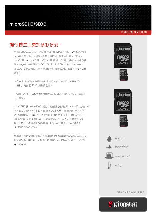
/FLASH請參閱背面之產品特性/規格 >>microSDHC/SDXC防水設計1防震與耐衝擊2耐高溫4可防機場 X 光3microSDHC/SDXC 記憶卡容量從 4GB 到 128GB ,可提供更多儲存空間來容納音樂、影片、圖片、遊戲-滿足您行動生活中的所有需求。
microSDHC 及 microSDXC 記憶卡可以使新一代的行動裝置發揮極致效能。
Kingston microSDHC/SDXC 記憶卡,以「Class 」作為速度級別,並保證最低資料傳輸速率,以確保使用 microSDHC 的裝置可發揮最佳效能。
•Class 4-最低資料傳輸速率為 4 MB/s 。
適用於入門款相機、遊戲 機和其他支援 SDHC 規格的裝置。
•Class 10 UHS-I -最低資料傳輸速率為 10 MB/s 。
適用於 HD 高畫質影 片錄製。
microSDHC 及 microSDXC 記憶卡的實際尺寸與標準 microSD 記憶卡相 同,此設計符合 SD 卡協會制定的記憶卡規格,且相容於 microSDHC 或 microSDXC 主機裝置。
搭配隨附的 SD 轉接卡時,可作為全尺寸SDHC/SDXC 記憶卡使用**。
若要確保相容性,請查看主機裝置 (例如,手機、平板電腦和數位相機) 上的 microSDHC 、microSDXC C 或 SDHC /SDXC 標誌。
無論您在何處使用行動裝置,Kingston 的 microSDHCC/SDXC 記憶卡都 值得您全心信賴。
每張記憶卡均通過百分之百的品質測試,並提供終 身產品保固。
讓行動生活更加多彩多姿。
本文件內容得隨時變更,恕不另行通知。
©2015 Kingston Technology Far East Co. Ltd (Asia Headquarters) No. 1-5, Li-Hsin Rd. 1, Science Park, Hsin Chu, Taiwan.版權所有。
sandisk transflash说明书

内存卡的使用说明SanDisk 闪迪microSDHC 手机存储卡是最时尚、最优质的音乐、视频、照片、游戏、文件和应用程序的手机存储卡片,只需将卡片轻轻插入手机匹配的卡槽,即可实现完美存储,即方便又可靠!想要不受约束的畅想手机娱乐、不受拘束的添加手机应用、不受存储容量的限制地玩转手机游戏世界、请选择SanDisk 闪迪microSDHC 手机存储卡。
想要运用手机存储尽可能多的高像素精致图片、高清视频以及完美音质歌曲的多媒体手机用户,请选择SanDisk 闪迪microSDHC 手机存储卡。
SanDisk 闪迪microSDHC 手机存储卡特点:手机存储卡特点:1. 兼容性强microSDHC 卡拥有稳定的读写速度和表现 2. Class4 速度等级评定(基于SD2.0 标准)3. 通过了最极端的环境条件测试4. 5 年质保* 1 gigabyte (GB) = 10 亿字节。
有些容量不适用于数据存储品牌简介闪迪是全球领先的闪存品牌。
SanDisk 于1988 年由Eli Harari 博士创立,是一家国际认可的非易失性内存技术权威机构,现已发展成为全球规模极大地创新闪存数据存储产品提供商。
闪迪是闪存卡的创造者,是USB 闪存盘领域的先锋。
1995 年11 月,SanDisk 成为了一家公开上市的公司,其纳斯达克股票代码为SNDK。
在2007 年9 月,闪迪在中国上海建立了第一个自有工厂。
领先产品:领先产品:存储卡:在手机存储卡市场,闪迪是美国市场的第一大品牌,是欧洲市场的领导者,也是俄罗斯和日本市场的领先品牌。
闪迪是全球数码相机及摄像机存储卡市场的领导者,我们高性能的闪迪Ultra 和闪迪Extreme 系列产品经常赢得业界奖项。
USB 闪存盘:闪迪是全球USB 闪存盘市场的领先品牌;亦为USB 闪存盘产品的先锋。
目前销售的USB 闪存盘为闪迪Ultra Backup 及Cruzer 系列. 知识产权:知识产权:SanDisk 目前拥有超过1700 个美国专利,超过1100 个国外专利,以及超过1100 个正在申请的美国专利,SanDisk 是全球唯一一家有权制造和销售所有闪存卡格式的企业,包括CompactFlash、SD、miniSD、microSD、Multi Media (RS—MMC)、Memory Stick PRO 以及相关的Memory Stick 产品、XD-Picture Card 和USB 闪存盘。
SanDisk ReadyCache SSD ExpressCache 用户手册说明书
SanDisk ReadyCache™ SSDExpressCache™,Condusiv™ Technologies Corporation 出品用户手册版本 1.1.0技术支持SanDisk KnowledgebaseSanDisk闪迪论坛联系 SanDisk目录概述 (3)最低系统要求 (3)包装内容 (3)在台式计算机上安装 SanDisk ReadyCache SSD (3)安装 ExpressCache 软件 (4)激活 ExpressCache (8)启用缓存 (11)禁用缓存 (11)清空缓存 (12)缓存状态 (12)帮助 (12)检查应用程序的更新 (13)缓存监视器 (13)选择语言 (14)寫入高速緩存緩衝區刷新 (15)关于 (16)系统托盘图标 (17)常见问题 (18)© 2013 SanDisk Corporation. 保留所有权利。
第 2 页,共 18 页概述SanDisk ReadyCache SSD 能够加速您现有 PC 的启动时间,缩短应用程序加载和反应的总时间。
本装置可以与台式计算机的现有硬盘配合使用,其设计面向运行 Windows® 7 操作系统的诸多系统。
与 Condusiv Tec hnologies 出品的 ExpressCache™软件配合使用时,本解决方案的高级缓存算法通过缓存常用的文件自动对数据进行管理,从而改善整体的存储性能。
最低系统要求∙Windows® 7/8∙1GB RAM (32 位) 和 2GB RAM (64 位)∙SATA II 或更高版本的端口∙宽带互联网连接(用于认证激活码)∙.Net Framework 3.5 或更高版本∙IE 浏览器版本 8 或者以上包装内容∙SanDisk ReadyCache SSD∙一根 SATA 数据线∙ 2.5” 到3.5” 适配器支架∙ExpressCache 软件激活码在台式计算机上安装 SanDisk ReadyCache SSD注意: SanDisk ReadyCache SSD 的设计旨在与现有系统的硬盘驱动器配合工作。
SD协议

一、SD规范介绍二、物理层规范三、SD Memory Card四、SDIO Card五、驱动编写一、SD2.0规范介绍1、版本SD spec1.0 低速度、低容量25M 2GSD spec1.1 高速度、低容量50M 2GSD spec2.0 高速度、高容量50M 32G2、SD规范包括(1) 物理层规范(2) 文件系统规范(3) SD卡安全规范(4) SD卡音频应用规范+其他相关应用规范(5) SD MC扩展规范移动设备(6) SDIO卡规范现在针对SD Memory 和SDIO两种类型的设备,所以下面内容只涉及子协议(1)、(6)。
3、符合SD2.0规范的设备SD卡MiniSD、MicroSD 1.0/1.1SDIO卡wifi 、GPSSDHC 2.0 最少支持class2SDXCCombo Card传输速度类型分为class0 旧的卡,class2 大于2MB/Sclass4 大于4MB/Sclass6 大于6MB/S二、物理层规范引脚SD模式SPI模式名称类型描述名称类型描述1 CD/DAT3 I/O/PP Card Direct/数据线[Bit3] CS I 片选(negtrue)2 CMD PP 命令/响应DI I 数据输入3 VSS S 电源地VSS S 电源地4 VDD S 电源正VDD S 电源正5 CLK I 时钟SCLK I 时钟6 VSS2 S 电源地VSS2 S 电源地7 DAT0 I/I/PP 数据线[Bit0] DO O/PP 数据输出8 DAT1 I/O/PP 数据线[Bit1] RSV9 DAT2 I/O/PP 数据线[Bit2] RSV2、总线传输模式SPI 串行传输、低速度SD 最多支持四线传输兼容MMC3 SD总线3.1 总线分为host device(1) comand 命令host to device 都是48位A、广播命令B、点对点命令(2) response 响应device to host根据内容不同分为R1、R3、R4、R7(48位)和R2(136位)初始化阶段,host给SD卡分配地址数据传输是有单块传输命令和多块传输命令,然后通过发送一个终止命令停止传输单块还是多块传输,通过host去配置命令先传msb 在lsb3.2 格式(1) 命令格式(2) 响应格式(3) 数据格式有两种(1) usual data bus 字节为单位发送(2) wide data bus 以块单位发送usual data :先发送高位,在发送低位一字节一字节发送wide data bus :整个数据块发送三、SD Memory Card1、初始化,发送命令读写卡中的寄存器发送命令完成读写、擦除等操作名称带宽描述CID 128 卡的ID号。
SD卡协议学习点滴(完整版本)

SD卡协议学习点滴(一)首先SD卡有所谓操作模式(operation mode)的概念,每种操作模式又具体对应一种或多种状态,主机通过发送命令可以使SD卡在不同的状态间转换,SD卡则接受命令,并根据自己现在所处状态做出不同的响应。
系统上电时刻或者搜寻SD卡时,SD卡控制器应该处于SD卡识别模式;SD卡在刚接入系统时刻也处于这种模式,并且处于此模式下的Idle状态。
SD卡识别模式:在这种模式下,控制器会检验SD卡的工作电压范围,识别SD卡类型,并要求它们发送各自的相对地址(Relative Card Address);这些操作在SD卡各自的CMD线上进行。
所有的操作均使用默认的 SD卡识别时钟频率(identification clock rate)SD卡复位:发送GO_IDLE_STATE(CMD0)到SD卡后,除处于非活动状态(Inactive state)之外的SD卡都会进入空闲状态(Idle state);在Idle状态,SD卡的CMD线处于输入模式,默认相对地址为0x0000,默认驱动寄存器设定为最低速度,最大驱动电流能力。
:工作条件检测在控制器和SD卡进行任何通信之前,控制器不清楚SD卡支持的工作电压范围,故而控制器首先使用默认的电压发送一条reset指令(CMD0),紧跟着的CMD8指令,用于取得SD卡支持工作电压范围数据。
SD卡通过检测CMD8的参数部分来检查控制器使用的工作电压,控制器通过分析回传的CMD8参数部分来校验SD卡是否可以在所给电压下工作。
如果SD卡可以在指定电压下工作,则它回送CMD8的命令响应字,其中包含check voltage, check pattern。
如果SD卡不支持所给电压,则SD卡不会给出任何响应信息,并继续处于Idle状态。
在PLV2.0(physical layer version2.0)下,在首次执行ACMD41之前,必须执行CMD8指令,用以初始化SDHC卡,SDHC卡根据是否接收到CMD8指令来鉴别控制器是否支持PLV2.0协议。
SD4.0协议标准完整版

SD 4.0 协议标准完整版历史版本注:本文是在网络流传的“沙贝@中科创达”SD2.0协议标准完整版的基础上,增加了SD4.0内容。
文中正文标注红色表示是SD4.0新增内容;标题标注红色表示为该标题以下的内容都是SD4.0新增加的。
关于UHS-II内容,有另外的翻译版本。
风语者 2016于西安1、总体描述Sd 存储卡,是为了满足安全、容量、性能、和环境需求的新型音视频电子存储卡。
Sd 卡包含一个内容保护机制,符合SDMI 标准,并且有更快的速度和更高的容量。
Sd 卡的安全系统采用双向认证和“新密码算法”来防止卡的内容被非法使用。
也可以对用户自己的数据进行非安全访问。
SD 卡也支持基于常用标准的第二安全系统,比如ISO-7816,这样就可以用于将SD 卡连接到共用网络和其他系统,来支持移动电子商务和数字签名的应用。
除了SD 卡外,还有SDIO 卡。
SDIO 卡规范在一个单独的规范中定义,命名为“SDIO卡规范”(可以从SD 协会得到)。
SDIO 规范定义了一个SD 卡可能包含不同的IO 单元同SD host 之间的接口。
SDIO 卡可以包含存储功能,以及IO 功能。
SDIO 卡的存储部分应该完全兼容SD 卡规范。
SDIO 卡基于并兼容SD 卡。
这种兼容包括机械、电气、电源、信号和软件。
Sdio 卡的意图是为移动电子设备在低功耗情况下提供高速数据读写。
一个主要目标是一个IO 卡插到非SDIO 主机中,不会引起物理损坏或者设备和软件的中断。
这种情况下IO 卡应该被简单的忽略掉。
一旦插入一个SDIO 主控,卡的检测将以常规的方法描述,即带有SDIO 规范扩展的SD 卡规范SD 卡通信是基于9-pin 接口(时钟,命令,数据x4,电源x3),设计在最大50M 频率以及低电下工作。
通信协议是本规范的一部分。
SD 规范分为几个文件:图1.1 SD规范文件●音频规范这个规范,以及其他应用规范,描述了一个特殊应用的规范(本文档是音频应用),以及实施需求●文件系统规范这个规范描述了存储在sd卡上的数据的文件格式化结构的规范(保护和非保护区域)●安全规范这个规范描述了内容保护机制和支持的特殊应用命令●物理层规范(本文档)这个规范描述了sd 卡使用的物理接口和命令协议。
SanDisk 4GB SDHC存储卡
SanDisk 4GB SDHC存储卡
佚名
【期刊名称】《《数字通信》》
【年(卷),期】2006(000)016
【摘要】SDHC存储卡家庭的成员正在扩大,包括SanDisk这样的专业存储卡制造厂商也正式推出了4GB容量的SDHC存储卡。
这款存储卡可存储超过2000张高分辨率图片、1000首MP3歌曲、8小时MPEG-4视频,并符合SDHC存储卡CLASS 2规格,具备大约2MB/s的读写速度,略慢于东芝和松下之前推出的同类产品。
这款SanDisk 4GB SDHC存储卡将捆绑MicroMate SDHC/SD读卡器进行销售,售价为199.99美元,约合人民币1600元。
【总页数】1页(P39)
【正文语种】中文
【中图分类】TP333
【相关文献】
1.极速高清——SanDisk Extreme HD Video SDHC存储卡 [J],
2.大肚能容4款4GB SDHC存储卡 [J],
3.突破好手-PNY 4GB SDHC存储卡 [J], 苍茫
4.感受极速 Lexar 专业4GB SDHC存储卡 [J], HappyFred
5.SANDISK推出4GB SDHC闪存卡 [J],
因版权原因,仅展示原文概要,查看原文内容请购买。
- 1、下载文档前请自行甄别文档内容的完整性,平台不提供额外的编辑、内容补充、找答案等附加服务。
- 2、"仅部分预览"的文档,不可在线预览部分如存在完整性等问题,可反馈申请退款(可完整预览的文档不适用该条件!)。
- 3、如文档侵犯您的权益,请联系客服反馈,我们会尽快为您处理(人工客服工作时间:9:00-18:30)。
上周看了卡的识别模式后,现在看看卡的数据传输模式,这是最重要的模式,勿庸置疑。
因为一些卡可能有时钟限制,fpp必须保持在fod,直到CSD寄存器被host读取。
host发出SEND_CSD(CMD9)来得到一些卡的专用数据,比如block length等等。
CMD7可以将卡置在传输模式。
只有一个卡可以在一个时间内在这个状态。
如果一个之前的卡在这个状态,那么与host的连接将会释放,并且回到stand-by 模式,当CMD7被发出保留相关卡地址0x0000,所有的卡传输都回到stand-by 状态。
这个可以用来识别新插入卡,并且不会重置以及注册的卡。
以及有RCA
的卡,不需要对识别命令相应。
*取消选择发生在一个特定的卡在重试CMD7的时候,发现RCA不匹配。
在另外一个卡和CMD线通用的时候,会自动发生。
因此,在SD卡系统中,系统需要负责做二选其一的事情。
-初始化后,通过公用CMD线工作,在这个情况下,取消选择会自动发生
-有意识去取消选择,如果CMD线是分开的
所有的数据通信在数据传输模式都是点对点的。
所有的命令都会有个在CMD线上的相应。
下面我们看下卡里的命令。
1 停止命令CMD12,能够忽略所有的读命令在任何时候,数据传输会中止,并且卡会返回到传输状态,读命令能够阻止块读CMD17,多块读CMD18,发送写保护CMD30,发送SCR ACMD51,和general命令在读模式中CMD56。
2 停止命令CMD12,能够中止所有的数据写命令在任何时候。
写命令必须在取消选择CMD7之前停止。
写命令被块写CMD24、CMD25,写CSD(CMD27),锁和解锁(CMD42),和在写模式的通用命令(CMD56)阻止。
3 当数据传输完成的时候,sd卡会在数据写状态。
之后如果写成功了,那么就去编程状态,如果失败了,就去传输状态。
4 如果block写操作被停止,并且block长度的crc是有效的,数据会被写入。
5 卡可以提供块写入的缓冲,下一个块可以在之前的块被写入的时候往卡里发送,如果所有的卡buffer都满了的话,sd卡就会在编程状态,DAT0线会被拉低
6 没有buffer提供给写CSD,写保护,和擦除。
当卡在忙于一个命令或前面的命令的时候,DAT0会被保持为低并且在编程状态。
实际上,如果CMD和DAT0被分开,并且host保持DAT0为忙,并且和其他卡的DAT0是分开的时候,host可能会读写其他卡如果这个卡是忙的时候。
7 参数设置命令是不被允许的,如果卡在编程中。
参数设置涉及块长度CMD16,擦除块开始CMD32,和擦除块结束CMD33。
8 卡被编程的时候,读命令是被不会允许的
9 把另外一张卡从stand-by转到传输状态的时候(CMD7),不会中止编程操作。
卡会切换到非连接状态,并且释放DAT线。
10 通过CMD7,一个卡可以在非连接状态被重新选择。
在这个情景下,卡会去编程状态,并且激活busy的鉴别状态。
11 重置卡通过CMD0,CMD15,会中止如何挂起或有效的操作,这个有可能破坏卡上的数据。
host有责任去阻止对数据的潜在伤害。
宽总线的选择和取消选择
4bits当然就是宽的了,是通过ACMD6来选择的。
在上电或者GO_IDLE后的默认的宽度是1bit。
ACMD6只在传输状态有效。
也就是说只有在CMD7,一个卡被选择了后,总线宽度才能改变。
下面看看读数据的格式
当数据没有被发送的时候,数据线是高的。
一个传输的数据块包括一个低的开始位,之后是连续的数据流。
这个数据流包含了负载的数据,错误校验位如果卡外面的ECC被使用。
数据流会以一个结束位结束。
数据传输是同步的操作于时钟的。
基于块的数据传输是通过CRC算法。
多项式产生是通过标准的CCITT格式:x16+x12+x5+1
对于块读操作,我们单独来说说
块传输的最大长度是通过READ_BL_LEN在CSD寄存器中定义的。
一些起始地址在一个物理块之内的长度,被READ_BL_LEN来定义的,可能会被传输,只是可能。
附着在每个块后面的CRC能够保证数据的完整性。
CMD17或者READ_SINGLE_BLOCK 开始一个块读,完成后返回到传输状态。
CMD18或者READ_MULTIPLE_BLOCK启动一个连续的多块操作。
块会被连续的传输,直到一个stop命令。
stop命令那,由于一系列的命令,有一个延迟,数据传输会在收到结束命令后结束。
如果主机用了多个块以及块的部分作为一个累加传输长度,而这个长度不是块对齐的。
卡会在第一个没有对齐没有对齐的块上,检测到块非对齐错误,在状态寄存器中设置ADDRESS_ERROR位,中断传输,并且在数据状态等待停止命令。
下面看下写数据的格式
其实那,这个数据传送格式,跟读的类似。
对于基于块的写数据传输,CRC被插入在每个数据块。
在这个操作之前那,卡会对接受到的数据块执行一个CRC检查,算法跟读的一样。
这个操作就阻止了写入数据的错误。
对于块写操作,我们单独来说说
块写入(CMD24-27,42,56),的意思是一个或多个块的数据从主机发送到卡,同时主机在每个块后面会挂1bit或4bits的CRC。
老san的卡那支持的块写入被块长度规定了,这个长度被CMD16设置,不管WRITE_BL_LEN设置为1k还是
2k bytes,都是512bytes。
下面有个表来说明这个事情
CSD值 | 当前块长度 | 写命令的开始地址
--------------------------------
最大块长度 | 不对齐 | 部分的 |
WRITE_BL_LEN | | |
----------------------------------------------------------------
512bytes dis dis 512bytes n*512bytes
1-kbytes dis dis 512bytes n*512bytes
2-kbytes dis dis 512bytes n*512bytes
当前块长度是被CMD16来设置的,小于512是允许的。
如果WRITE_BL_PARTIAL是被允许的,那么小的块,即使是1byte也是被允许的。
如果CRC失败了,那么卡会丢弃数据,不写入,并将要传输的多个块也会被忽略,并且在DAT线上显示错误。
多块写入命令会被经常用到,因为速度比单块操作快得多。
如果host用了一个或几个块的部分,并且长度不是块对齐,而且块不对齐是不被允许的,那么卡会检查到块不对齐的错误,并且中止操作在不对齐的块操作之前。
卡会设置ADRRESS_ERROR错误在状态寄存器中,并且忽略进一步的和数据传输,在接受数据状态等待中止命令。
在写保护的区域写入数据会被中止。
在这个情况下,卡会设置WP_VIOLATION位。
对CSD寄存器编程不需要知道之前的块长度的设置,传输的数据还是有crc保护的。
如果CSD寄存器的一部分被存储在ROM中,那么这个不被改变的部分必须和收buffer中的对应。
如果不配对,那么卡会报错,并且不改变任何reg的值。
一些卡可能需要一个非常长的,不能预测的时间来完成一个块的数据写入。
当收完一个块的数据,并且crc检查ok,卡会把DAT0拉低,如果写buffer满了或者不能接受WRITE_BLOCK命令发送的新的数据。
这个时候host需要通过CMD13来查询卡的状态。
状态位READY_FOR_DATA表示了是否卡能接受新的数据。
如果卡不能接受数据,那么主机可能通过CMD7释放此卡,这样卡就会进入非连接状态,并且在无需中断写操作的情况下释放DAT线(这样卡就可以自己偷偷的写了,而主机也去干别的事情了)。
当主机重新选择这个卡的时候,需要通过拉低DAT 来看是不是写入还在进行来检查busy。
实际上啊,主机可能执行同时的写入给几个卡,通过inter-leaving的技术来完成(其实这就是SSD的雏形了),interleaving可以通过别的卡忙的时候来分别操作每个卡。
这个操作是通过CMD 和DAT0-3来完成的。
(再多说一句,对于SSD,flash完全在忙,host可以在sdram开始往nandflash写数据的时候闪人,去干别的事情,而flash的dma或者master来完成写入的事情。
host就可以去命令其他的空闲flash来写入)。
发送写模块的数目?号码!
由于系统采用流水线的机制来控制数据管理,在一些情况,如果一个多块写操作中间发生了错误,系统不知道最后那个写好的块是哪个。
而卡会相应ACMD22一个带有写好的块的号码(这个号码应该是卡的编号)。
