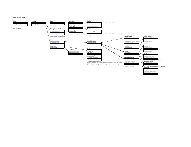
罗斯蒙特8800D涡街流量计Hart菜单树
8800D质量涡街流量计和eh涡街流量计价格(20190402180852)

8800D 质量涡街流量计和eh 涡街流量计价格标题 :差压式蒸汽流量计和涡街气体流量计价格库号: JX098548 价格:百度搜【润联网】查询主要技术参数:智能气体涡轮流量计采用先进的超低功耗单片微机技术研制的涡轮流量传感器与显示积算一体化的新型智能仪表,采用双排液晶现场显示瞬时流量和累计流量,具有机构紧凑、读数直观清晰、可靠性高、不受外界电源干扰、抗雷击、成本低等明显优点。
仪表具备仪表系数六点修正,智能补偿仪表系数非线性,并可进行现场修正。
智能气体涡轮流量计流量范围宽( Qmax/Qmin≥ 20:1 ),重复性好,精度高,可达 1.0 级,压力损失小,始动流量低,可达0.6m3/h ;智能化仪表系数多点非线性修正;仪表系数、累计流量值掉电十年不掉。
气智能气体涡轮流量计高清晰液晶显示器同时显示瞬时流量( 4 位有效数字)及累积流量(8 位有效数字,带清零功能)。
所有有效数据掉电后保持 10 年不丢。
该类涡轮流量计均为防爆产品,防爆等级为: ExdIIBT6 。
温度压力补偿型气体涡轮流量计是吸取了国内外流量仪表先进技术经过优化设计,综合了气体力学、流体力学、电磁学等理论的集温度、压力、流量传感器和智能流量积算仪于一体的新一代高精度、高可靠性的气体精密计量仪表,具有出色的低压和高压计量性能,多种信号输出方式以及对流体扰动的低敏感性,广泛适用于气体的标题 :dy 涡街流量计和数字式涡街流量计价格库号: JX098561 价格:百度搜【润联网】查询主要技术参数:金属管浮子流量计具有结构简单、工作可靠、适用温度范围广、精度较高、价格便宜等特点。
本系列流量计为现场指示型,有下进上出、左进右出和下进侧出三种安装形式。
可广泛适用于国防、化工、石油、冶金、电力、环保、医药和轻工业等部门的液体、气体流量测量。
二、沼气流量计结构原理LZ 系列金属管浮子流量计由二部分组成:①传感器-测量管及浮子;②信号变送器 -指示器;传感器的触液材质有四种:不锈钢、哈氏合金、钛材、不锈钢衬 PTFE; 用户可根据不同的工艺压力及介质的腐蚀性要求,选择不同的触液材质,来满足工艺的耐压及介质防腐的需要。
8732 电磁流量计,8800 涡街流量计操作手册
易于使用 -- 组态,维护容易
• 出厂时已完成设置
• 安装基本要求
– 至少前10D,后5D直管段
前、后直管段
• 通用备件
– 压电传感器和电子部件
易 用
先进的自诊断功能(便于维护)
• 电子部件的诊断
–电子部件故障 –电子部件标定
电子部件的 诊断
• 传感器的诊断
–检验传感器是否正常运行 –判断传感器故障
这个扭曲运动由流量管外的传感器感应传感器压电元件感应此交变力并且转换为交流电信号电信号的频率就是涡街发生体的频率涡街结构可靠性传感器与过程介质隔离易于维护超级抗振动能力质量平衡在传感器中每一部分的质量相对于压电晶体是平振动引起的力在传感器抵消并且被有效消除不会被传感器采集发生体的质量也是平衡的因此在振动的环境中对于发生体的基准点没有扭曲vibrationpiezoelectriccrystalshedderbarmeterbodysensordisengagedfrommeterbodyillustrationpurposes易于使用前后直管段先进的自诊断功能便于维护电子部件的诊断传感器的诊断过程的诊断电子部件的诊断电子部件故障电子部件标定传感器的诊断检验传感器是否正常运行判断传感器故障过程的诊断判断过程中出现的问题信号强度的测量先进的流量模拟功能内置用于诊断的流量信号发生器iso电子认证测试点利用一个外接信号发生器即可使用iso电子认证输入点旋涡频率输出电子部件的诊断传感器阻抗检测检验传感器是否正常运行判断传感器故障传感器的诊断传感器旋涡频率使用户能够了解管道内的实际情况对于特定过程可用于优化滤波器信号强度实际信号与触发水平的比例信号强度的测量帮助判断过程中出现的干扰问题过程的诊断
不导电 或 有涂层管道
LOI
ROSEMOUNT8800D涡街流量计
00813-0600-4004, Rev DA 2007 年 3 月
8800D 型涡街流量计
HART® 和基金会 ™ 现场总线协议
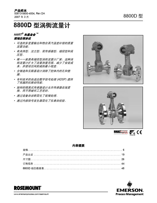
• 可选的多变量输出和饱合蒸汽温度补偿的质量 流量功能。
• 有夹持型、法兰型、双传感器型,缩径型和高 压型。
• 唯一一家具有缩径型涡街流量计厂家,这种涡 街流量计扩大了流量测量范围,减少了安装成 本,并使项目风险减到最小程度。
缩径型 1, 11/2, 2, 3, 4, 6, 8, 10, 和 12 英寸 (DN 25, 40, 50, 80, 100, 150, 200, 250, 和 300)
管道等级
过程管道等级 10, 40, 80, 和 160 序列。
注意: 正确的管道口径必须用 HART 手操器或 AMS 输入。除非另有指 定,所有流量计出厂时以 Schedule40 系列的管道内径进行组态。
RD=
V-----D-----ρ-
µcp
表 1. 最小可测雷诺数
仪表规格 ( 英寸 / DN) 1/2 到 4/15 到 100 6 到 12/150 到 300
雷诺数极限值
最小 10000 最小 20000
表 2. 最小可测量速率(1) (使用两个值中较大的一个)
液体(2) 气体
英尺 / 秒 36/ρ 或 0.7 36/ρ 或 6.5
• 抗振动性 - 质量平衡传感器系统,和专利技术 的自适应数字信号处理器 (ADSP) 提供了优越 的抗振性。
• 可在线更换传感器 - 传感器与工艺过程隔离, 可在线更换,所有口径具有通用传感器,所以 备件简单。
• 简化故障处理 - 设备自诊断功能能现场鉴定流 量计电子部件和传感器,无需断开工艺过程。
(完整word版)罗斯蒙特质量流量计操作说明
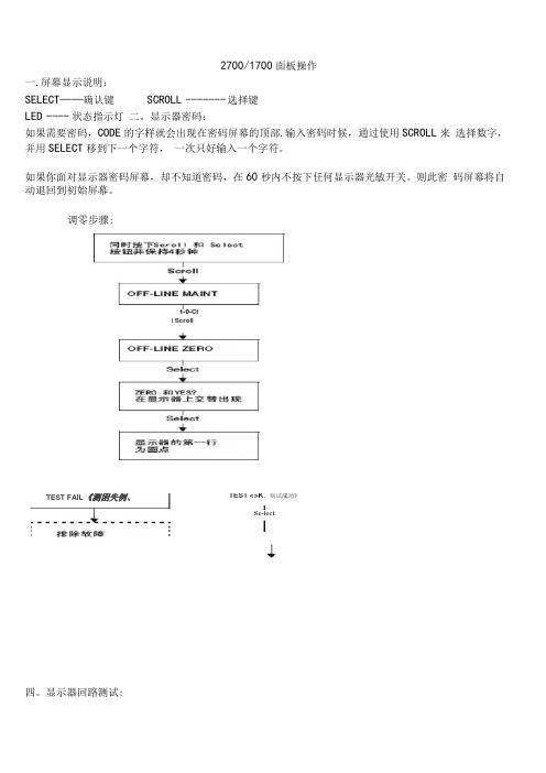
2700/1700面板操作一.屏幕显示说明:SELECT——确认键SCROLL ------- 选择键LED ---- 状态指示灯二。
显示器密码:如果需要密码,CODE的字样就会出现在密码屏幕的顶部.输入密码时候,通过使用SCROLL来选择数字,并用SELECT移到下一个字符,一次只好输入一个字符。
如果你面对显示器密码屏幕,却不知道密码,在60秒内不按下任何显示器光敏开关。
则此密码屏幕将自动退回到初始屏幕。
调零步骤:四。
显示器回路测试:TEST <>K。
则试成功》ISe-lectI1-0-CtI ScrollTEST FAIL《测困失例、五. Set MA01Set MA024 mA12 mA20 mASe eelScroll3e eel正码?二>SelectScrollOFF-LINE SIMSelectScrollScroll1 KMzIDKHzSclent读取接受设餐的输出HPYesSst D01Set D02SelectScrollOHOFP阱I M]读取接克设备的箍出致T回路测试成功女%,人出?狂.停止历具ScrollExh检登回率接线排除输出故慎显示器查看报警:LED指示灯状态及报警查看状态指示灯的状态报警优先级魄色无报警-正常运行模式鼻电闪姆”已改正但尚未信认的状态黄色已偏认的低强度报警黄色闪探⑴未稳认的做强度报警虹笆己碉认的高强度指警红色闪峭'未询认的高强虚报警11)如果报警菜单被禁止,则无沫箱认报警,在这种情况下.状态指示LEim不再闪保工报警按照报警队列中的优先级排列,要查看队列中某指定报警:L同时按下配Ml和Select按钮,当屏幕上出现"EE ALARM'」札松开按钮“ 参阅图7-1.2 .按Select按钮,3 .如果屏幕上交替出现“AGK ALL”时,则按配FQ11按钮,4 .如果屏幕上出现"0 ALARN” ,则到第6步,5,按配ell按钮查看队列中的每个技警.要了解显示帚显示的报警代码的含义请参阅翦1QJ1幸节,6,按Scroll按钮直到解幕上出现“EXIT” ”7.按Select按祗六.管理累积量和库存量:(完整word 版)罗斯蒙特质量流量计操作说明宫动/停止所有累租值和质存量⑵进行酬重副可定翻值出现空位七:测量单位设置:SELECT+SCROLL 按 4 秒 ----- ► SEE ALARM ---- ► [SCROLL] ---- ►OFFLINE MAINTAIN -------- ► [SELECT]- ..... > [SCROLL] ----- ►CONFIG ----- ► [SELECT] ---- ► MASS ------- [SELECT] ------- ►SELECTI 如果有需求.输入密码SELECTSELECT如果有需求,输入密码SELECTSELECT复位!特定累积值⑴深部翻屏直到特定累积值可以按SCROLL选择你要的单位> 选定后按SELECT按SCROLL 直到出现EXIT ----- ► [SELECT]体积单位和密度单位设置和上述步骤相同八量程设置(LRV URV)[SELECT+SCROLL] 按 4 矛秒/ SEE ALARM ------- ► [SCROLL] --- ►OFFLINE MAINTAIN --------- ► [SELECT^ ------ ►继续按SCROLL 直到出现MAO1[SELECT] ----------------------------- k SRC MAO1 ------ k [SELECT]MFLOW ---- ► [SELECT]----- SRC MAO1 ——[SCROLL]4 MAO1 ----- ►输入最小量程------ ►[SCROL L+SELEC T] 4 MAO1 ------- ► [SCROLL] ------ ►——20HMAO1 ----------- ►[SELECT] 输入最大量程------ ►[SELECT+SCROLL]--------------- > 20 MAO1>[SCROLL]EXIT ---- ^ 按SELECT 退出.其他量程设置和上述步骤相同。
8800D型涡街流量计在供热计量方面的一些问题及解决方案
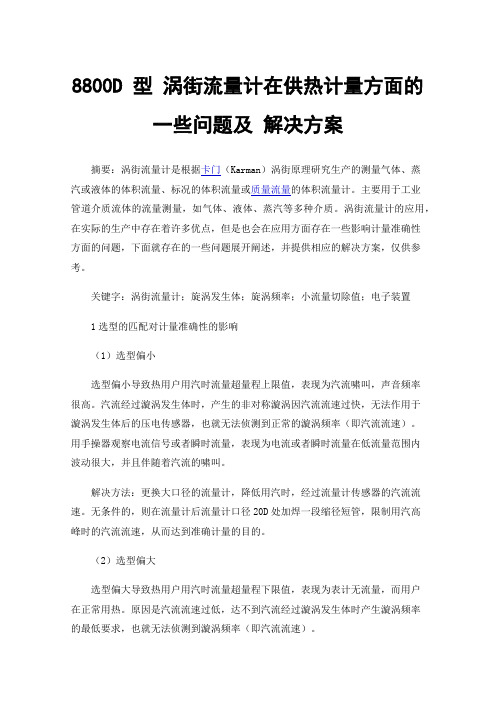
8800D 型涡街流量计在供热计量方面的一些问题及解决方案摘要:涡街流量计是根据卡门(Karman)涡街原理研究生产的测量气体、蒸汽或液体的体积流量、标况的体积流量或质量流量的体积流量计。
主要用于工业管道介质流体的流量测量,如气体、液体、蒸汽等多种介质。
涡街流量计的应用,在实际的生产中存在着许多优点,但是也会在应用方面存在一些影响计量准确性方面的问题,下面就存在的一些问题展开阐述,并提供相应的解决方案,仅供参考。
关键字:涡街流量计;旋涡发生体;旋涡频率;小流量切除值;电子装置1选型的匹配对计量准确性的影响(1)选型偏小选型偏小导致热用户用汽时流量超量程上限值,表现为汽流啸叫,声音频率很高。
汽流经过漩涡发生体时,产生的非对称漩涡因汽流流速过快,无法作用于漩涡发生体后的压电传感器,也就无法侦测到正常的漩涡频率(即汽流流速)。
用手操器观察电流信号或者瞬时流量,表现为电流或者瞬时流量在低流量范围内波动很大,并且伴随着汽流的啸叫。
解决方法:更换大口径的流量计,降低用汽时,经过流量计传感器的汽流流速。
无条件的,则在流量计后流量计口径20D处加焊一段缩径短管,限制用汽高峰时的汽流流速,从而达到准确计量的目的。
(2)选型偏大选型偏大导致热用户用汽时流量超量程下限值,表现为表计无流量,而用户在正常用热。
原因是汽流流速过低,达不到汽流经过漩涡发生体时产生漩涡频率的最低要求,也就无法侦测到漩涡频率(即汽流流速)。
解决方法:更换小口径的涡街流量计,保证热用户在正常用汽时的流量计量要求。
2表计管道内异物对流量计计量的影响涡街流量计的测量原理,需要在管道内设置一定宽度的漩涡发生体。
这就决定了对所测量的介质的洁净度要求。
测量介质要求无颗粒,无絮状物,并且在涡街流量计安装投用前对需管道进行彻底地吹扫,排污干净,确保涡街流量计投入运用后,漩涡发生体不被诸如石子、焊渣等异物冲击而磨损,甚至损坏、变形。
特别注意的是,流量计前的阀门安装最好采用带加强内环的金属石墨缠绕垫片,或者焊接阀门。
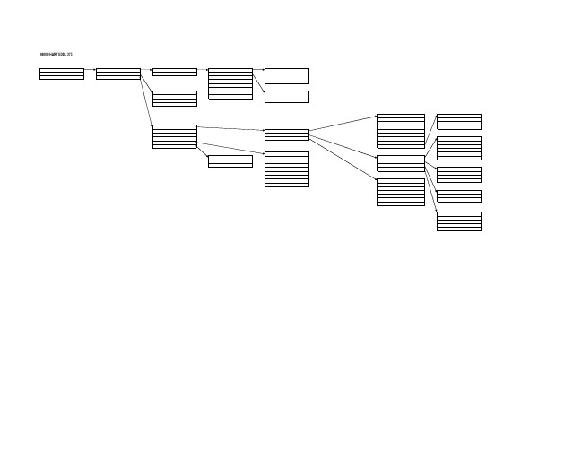
涡街流量计HART475菜单8800D
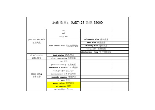
诊断/服务
test/status 测试/状态
flow simulation 流量仿真
basic setup
基本组态
tag 位号
process config 过程配置
reforence K factor K系数从
flange type 法兰尺寸
mating pipe I.D 管道内径
process fluid (liquid液体)
pv lrv 量程下限
pv URv 量程上限
variable mapping 变量映射
pv unit 单位
range values量程范围
pv damping阻尼
auto adjust filter
detailed setup
详细设置
characterized meter
仪表特性
K-factor K系数
mating pipe I.D
flange type
涡街流量计HART475菜单8800D
process variable
过程变量
pv
pv%
anlg out
view others vars其它变量趋势
volumetric flow 体积流量
mass flow 质量流量
velocity flow 速度流量
totalizer 累积流量
electronics temp 电子电路温度
lowpass filter低通角ห้องสมุดไป่ตู้率
trigger level 触发水平
filter restore 恢复出厂滤波
pv damping 阻尼
LFC response 小流量切除响应
8800D
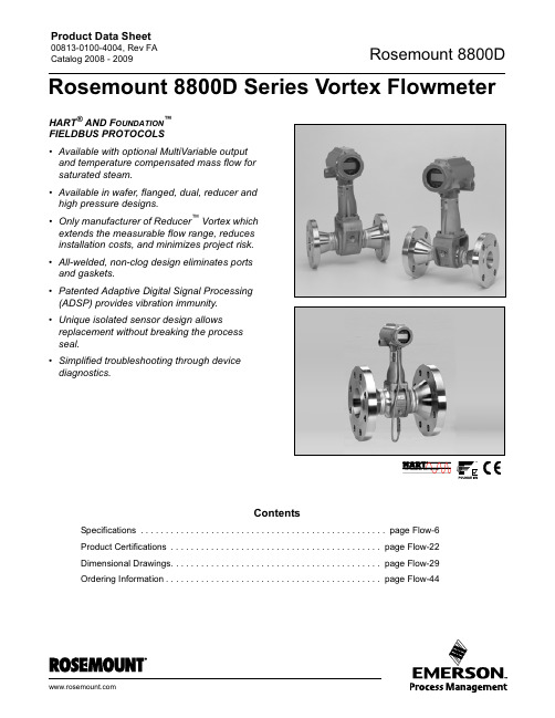
Product Data Sheet00813-0100-4004, Rev FA Catalog 2008 - 2009 Rosemount 8800DHART® AND F OUNDATION™FIELDBUS PROTOCOLS•Available with optional MultiVariable output and temperature compensated mass flow for saturated steam.•Available in wafer, flanged, dual, reducer and high pressure designs.•Only manufacturer of Reducer™ Vortex which extends the measurable flow range, reduces installation costs, and minimizes project risk.•All-welded, non-clog design eliminates ports and gaskets.•Patented Adaptive Digital Signal Processing (ADSP) provides vibration immunity.•Unique isolated sensor design allows replacement without breaking the process seal.•Simplified troubleshooting through devicediagnostics.ContentsSpecifications . . . . . . . . . . . . . . . . . . . . . . . . . . . . . . . . . . . . . . . . . . . . . . . . . page Flow-6Product Certifications . . . . . . . . . . . . . . . . . . . . . . . . . . . . . . . . . . . . . . . . . . page Flow-22Dimensional Drawings. . . . . . . . . . . . . . . . . . . . . . . . . . . . . . . . . . . . . . . . . . page Flow-29Ordering Information. . . . . . . . . . . . . . . . . . . . . . . . . . . . . . . . . . . . . . . . . . . page Flow-44 Rosemount 8800D Series Vortex FlowmeterProduct Data Sheet00813-0100-4004, Rev FACatalog 2008 - 2009Flow-2Rosemount 8800DTHE ROSEMOUNT 8800D DELIVERS RELIABILITY•Rosemount Reliability -The 8800D Vortex eliminates impulse lines, ports, and gaskets to improve reliability.•Non-clog Design - Unique gasket-freeconstruction which has no ports that can clog.•Vibration Immunity - Mass Balancing of the sensor system, and Patented Adaptive Digital Signal Processing (ADSP) provide Vibration immunity.•Replaceable Sensor - The sensor is isolated from the process and can be replaced without breaking the process seals. All line sizes use the same sensor design allowing a single spare to serve every meter.•Simplified Troubleshooting - DeviceDiagnostics enable field verification of Meter Electronics and Sensor with no process shutdown.THE ROSEMOUNT 8800D OFFERING•The 8800D is available in wafer style meter bodies for 1/2 through 8 in. line sizes, andASME B16.5 (ANSI), DIN, or JIS flanged style meter bodies for 1/2 through 12 in. line sizes. •Alignment rings, provided with eachwafer-style flowmeter, ensure that the meter body is properly centered with the adjacent piping.•Both wafer and flanged style meter bodies are available in 316L stainless steel and nickel alloy materials of construction.•Available up to ANSI class 1500 for 1 through 8 in. (25 mm through 200 mm) and ANSI class 900 for 1/2 in. (15 mm) through 8 in. (200 mm).•Available with F OUNDATION fieldbus functionality which includes DeviceDiagnostics and PlantWeb Alerts.Product Data Sheet00813-0100-4004, Rev FA Catalog 2008 - 2009Flow-3Rosemount 8800DTHE ROSEMOUNT 8800DR REDUCER ™ VORTEX EXTENDS THE MEASURABLEFLOW RANGE AT A REDUCED COST•Rosemount Reliability - Designed with same electronics, sensor, and meter body as the 8800D.•Reduced Cost - Eliminates field assembly and welding of separate reducers and piping reducing installed cost by as much as 50%.•Extended Measurable Flow - Low-end flow range is doubled with the Rosemount 8800DR Reducer Vortex.•Reduced Project Risk - Reducer Vortex and the Standard Vortex have the sameface-to-face dimension. As a result either meter can be used without affecting pipe layout.•Available as flanged meter for 1 through 12 in. stainless steel and nickel alloy materials of construction.•Available with F OUNDATION fieldbus functionality.THE DUAL-SENSOR VORTEX FLOWMETER•Safety Integrated Systems (SIS) - Ideal solution where redundant flow signals are required.•Rosemount Reliability - Designed with same electronics, sensor, and meter body as the 8800D.•Redundant Flow Measurement - Dual Vortex meter is constructed of two complete vortex meters: sensor, electronics, and shedder bar (1). The meters are welded together and flow calibrated to provide an accurate single flowmeter with two independent flow measurements.•Available as flanged meter for 1/2 through 12 in. stainless steel and nickel alloy materials ofconstruction.(1)All 10 in (250 mm) and 12 in (300 mm) dual style vortex meters have a single shedder bar. 6 in (150 mm) and 8 in (200 mm) dual style vortex meters with 900# or 1500# flange ratings have a single shedder bar.Product Data Sheet00813-0100-4004, Rev FACatalog 2008 - 2009Flow-4Rosemount 8800D8800D MULTIVARIABLE VORTEX REDUCES INSTALLATION COSTS, SIMPLIFIESINSTALLATION, AND IMPROVES PERFORMANCE IN SATURATED STEAM•MultiVariable Vortex DesignIncorporates temperature sensor into the vortex meter using the shedder bar as a thermowell, which keeps the vortex andtemperature sensor isolated from process for easy verification and replacement.•Temperature Compensated Capability for Saturated SteamCalculates density from measured process temperature and uses the calculated density to provide a temperature compensated mass flow.•Increased performance in Saturated SteamPerformance in saturated steam is improved due to the fact that the electronics will be compensating for changes in the process temperature.•Reduces Installed CostsMultiVariable Vortex eliminates the need for an external thermowell and temperature sensor.•Output OptionsCan map independent variables to analog output, pulse output, or HART burst variables.•Available with Flow Computer for additional functionalityIntegrate the MultiVariable Vortex with a pressure transmitter for full pressure and temperature compensation of superheated steam and various gases.•Remote Mount ElectronicsAlso available with remote mounted electronics up to 75 ft. (23 m)When you integrate the MultiVariable Vortex with a Rosemount Flow Computer, you get:•Remote Communications •Heat Calculations •Remote Totalization •Peak Demand Calculation •Datalogging CapabilitiesPlease see Product Data Sheet 00813-0100-4005 for more information on the Rosemount FlowComputer.Product Data Sheet00813-0100-4004, Rev FA Catalog 2008 - 2009Flow-5Rosemount 8800DROSEMOUNT 8800D VORTEX FLOWMETER WITH F OUNDATION FIELDBUSThe software for the 8800D Flowmeter withF OUNDATION fieldbus permits remote testing and configuration using any F OUNDATIONfieldbus-compliant host, such as the DeltaV system from Emerson Process Management.Transducer BlockThe transducer block calculates flow from sensor frequency. The calculation includes information about damping, shedding frequency, K-factor, service type, pipe ID, and diagnostics.Resource BlockThe resource block contains physical transmitter information, including available memory,manufacturer identification, device type, software tag, and unique identification.Backup Link Active Scheduler (LAS)The transmitter is classified as a device link master. A device link master can function as a Link Active Scheduler (LAS) if the current link master device fails or is removed from the segment.The host or other configuration tool is used todownload the schedule for the application to the link master device. In the absence of a primary linkmaster, the transmitter will claim the LAS and provide permanent control for the H1 segment.DiagnosticsThe transmitter automatically performs continuous self-diagnostics. The user can perform on-line testing of the transmitter digital signal. Advanced simulation diagnostics are available. This enables remote verification of the electronics via a flow signal generator built into the electronics. The sensorstrength value can be used to view the process flow signal and provide information regarding filter settings.F OUNDATION Fieldbus Function BlocksAnalog InputThe AI function block processes the measurement and makes it available to other function blocks. The AI function block also allows filtering, alarming, and engineering unit changes.The 8800D Flowmeter with F OUNDATION fieldbus comes standard with two AI function blocks (1 block for flow and 1 block for signal strength).Proportional/Integral/DerivativeThe optional PID function block provides asophisticated implementation of the universal PID algorithm. The PID function block features input for feed forward control, alarms on the process variable, and control deviation. The PID type (series or Instrument Society of America [ISA]) is user-selectable on the derivative filter.IntegratorThe standard integrator block is available for totalization of flow.SetupBasic setup requires connecting the transmitter to a fieldbus network or 375 Handheld Communicator. The F OUNDATION fieldbus- compliant host will automatically establish communication with the device.The Rosemount 8800D Flowmeter can be easily configured using the DeltaV system.User-configurable parameters include: tag, scaling and units, service type, damping, process density, pipe inside diameter (ID)(1), and process temperature (1).Tagging information can be entered into the transmitter to allow identification and a physical description. 32-character tags are provided for identification of the transmitter and each function block.(1)Process temperature and pipe ID have known effects on the K-factor. The 8800D software automaticallyaccounts for these effects by compensating the K-factor.Product Data Sheet00813-0100-4004, Rev FACatalog 2008 - 2009Flow-6Rosemount 8800DSpecificationsThe following specifications are for the Rosemount 8800D, Rosemount 8800DR, and Rosemount 8800DD, except where noted.FUNCTIONAL SPECIFICATIONSServiceLiquid, gas, and steam applications. Fluids must be homogeneous and single-phase.Line SizesWafer 1/2, 1, 11/2, 2, 3, 4, 6, and 8 inches(DN 15, 25, 40, 50, 80, 100, 150, and 200)Flanged and Dual-Sensor Style 1/2, 1, 11/2, 2, 3, 4, 6, 8, 10, and 12 inches(DN 15, 25, 40, 50, 80, 100, 150, 200, 250, and 300)Reducer1, 11/2, 2, 3, 4, 6, 8, 10, and 12 inches(DN 25, 40, 50, 80, 100, 150, 200, 250, and 300)Pipe SchedulesProcess piping Schedules 10, 40, 80, and 160.NOTEThe appropriate bore diameter of the process piping must be entered using the HART Communicator or AMS. Meters will be shipped from the factory at the Schedule 40 default value unless otherwise specified.Measurable Flow RatesCapable of processing signals from flow applications which meet the sizing requirements below. To determine the appropriate flowmeter size for an application, process conditions must be within the Reynolds number and velocity limitations for the desired line size provided in Table 1, Table 2, Table 3, and Table 4.NOTEConsult your local sales representative to obtain a computer sizing program that describes in greater detail how to specify the correct flowmeter size for an application.The Reynolds number equation shown below combines the effects of density (), viscosity (cp ), pipe inside diameter (D), and flow velocity (V).TABLE 1. Minimum Measurable Meter Reynolds Numbers1/2 through 4/15 through 10010000 minimum 6 through 12/150 through 30020000 minimumTABLE 2. Minimum Measurable Meter Velocities (1)(Use the larger of the two values)(1)Velocities are referenced to schedule 40 pipe.Liquids (2)(2)The minimum measurable velocity for the 10in. line size is 0.94 ft/s(.29m/s) and 1.11 ft/s (.34m/s) for the 12in. line size.Gases33 TABLE 3. Maximum Measurable Meter Velocities (1)(Use the smaller of the two values)(1)Velocities are referenced to schedule 40 pipe.Liquids Gases(2)(2)Accuracy limitations for gas and steam for Dual-style meters (1/2”to 8”): max velocity of 100 ft/s (30.5 m/s).33R D VD ρµc p-----------=36/ρ or 0.754/ρ or 0.2236/ρ or 6.554/ρ or 2.090,000/ρ or 25134,000/ρ or 7.690,000/ρ or 250134,000/ρ or 76Product Data Sheet00813-0100-4004, Rev FA Catalog 2008 - 2009Flow-7Rosemount 8800DProcess Temperature Limits Standard–40 to 450 °F (–40 to 232 °C)Extended–330 to 800 °F (–200 to 427 °C)MultiVariable (MTA option)–40 to 800 °F (–40 to 427 °C)★ Use above 450 °F (232 °C) requires Extended Sensor Output Signals4–20 mA Digital HART Signal Superimposed on 4–20 mA signalOptional Scalable Pulse Output0 to 10000 Hz; transistor switch closure with adjustable scaling via HART communications; capable of switching up to 30 V dc, 120 mA maximumDigital Foundation fieldbus signalManchester-encoded digital signal that conforms to IEC 1158-2 and ISA 50.02. Analog Output AdjustmentEngineering units and lower and upper range values are user-selected. Output is automatically scaled to provide 4 mA at the selected lower range value, 20mA at the selected upper range value. No frequency input is required to adjust the range values.Scalable Frequency AdjustmentThe scalable pulse output can be set to a specific velocity, volume, or mass (i.e. 1 pulse = 1 lb). The scalable pulse output can also be scaled to a specific rate of volume, mass, or velocity (i.e. 100 Hz = 500 lb/hr).Ambient Temperature LimitsOperating–58 to 185 °F (–50 to 85 °C)–4 to 185 °F (–20 to 85 °C) for flowmeters with local indicatorStorage–58 to 250 °F (–50 to 121 °C)–50 to 185 °F (–46 to 85 °C) for flowmeters with local indicatorPressure LimitsFlange Style MeterRated for ASME B16.5 (ANSI) Class 150, 300, 600, 900, and 1500, DIN PN 10, 16, 25, 40, 64, 100, and 160, and JIS 10K, 20K, and 40K Reducer Style MeterRated for ASME B16.5 (ANSI) Class 150, 300, 600, and 900, DIN PN 10, 16, 25, 40, 64, 100, and 160.Dual Sensor Style MeterRated for ASME B16.5 (ANSI) Class 150, 300, 600, 900, and 1500, DIN PN 10, 16, 25, 40, 64, 100, and 160, and JIS 10K, 20K, and 40K Wafer Style MeterRated for ASME B16.5 (ANSI) Class 150, 300, and 600, DIN PN 10, 16, 25, 40, 64, and 100, and JIS 10K, 20K, and 40KWeld-End Style MeterW1 Welds to Schedule 10 mating pipeMax Working Pressure 720 psig (4.96 MPa-g)W4 Welds to Schedule 40 mating pipeMax Working Pressure 1440 psig (9.93 MPa-g)W8 Welds to Schedule 80 mating pipeMax Working Pressure 2160 psig (14.9 MPa-g)W9 Welds to Schedule 160 mating pipe Note: 1” (25 mm), and 1.5” (40 mm) weld to Schedule 80 mating pipeMax Working Pressure 3600 psig (24.8 Mpa-g)Power SupplyHART AnalogExternal power supply required. Flowmeteroperates on 10.8 to 42 V dc terminal voltage (with 250-ohm minimum load required for HART communications, 16.8 V dc power supply is required)Foundation fieldbusExternal power supply required. Flowmeteroperates on 9 to 32 V dc, 17.8 mA nominal, 20.0 mA maximum. Power Consumption One watt maximumProduct Data Sheet00813-0100-4004, Rev FACatalog 2008 - 2009Flow-8Rosemount 8800DLoad Limitations (HART Analog)Maximum loop resistance is determined by the voltage level of the external power supply, as described by:NOTEHART Communication requires a minimum loop resistance of 250 ohms.Optional LCD IndicatorThe optional LCD indicator is capable of displaying:•Primary Variable •Velocity Flow •Volumetric Flow •Mass Flow •Percent of Range•Analog Output (if applicable)•Totalizer (Output Code “D” and “P” Only)•Shedding Frequency•Pulse Output Frequency (if applicable)•Electronics Temperature (Output Code “D” and “P” Only)•Process Temperature (MTA Option Only)•Calculated Process Density (MTA Option Only)If more than one item is selected, the display will scroll through all items selected.Enclosure RatingFM Type 4X; CSA Type 4X; IP66Permanent Pressure LossThe approximate permanent pressure loss (PPL) from the Rosemount 8800D flowmeter is calculated for each application in the Vortex sizing software available from your local Rosemount representative. The PPL is determined using the equation:where:Minimum Back Pressure (Liquids)Flow metering conditions that would allow cavitation, the release of vapor from a liquid, should be avoided. This flow condition can be avoided by remaining within the proper flow range of the meter and by following appropriate system design.For some liquid applications, incorporation of a back pressure valve should be considered. To prevent cavitation, the minimum back pressure should be:R max =41.7(V ps – 10.8)V ps =Power Supply Voltage (Volts)R max =Maximum Loop Resistance (Ohms)Power Supply (Volts)L o a d (O h m s )Operating Region12501000500010.842PPL =Permanent Pressure loss (psi or kPa)Where:f =Density at operating conditions (lb/ft 3 orkg/m 3)Q =Actual volumetric flow rate (Gas = ft 3/min orm 3/hr; Liquid = gal/min or l/min)D =Flowmeter bore diameter (in.or mm)A =Constant depending on meter style, fluid typeand flow units. Determined per following table:TABLE 4. Determining the PPL8800DF/W 3.4 ϫ 10-5 1.9 ϫ 10-30.4251188800DR 3.91 ϫ 10-5 2.19 ϫ 10-30.4891368800DD (1)(1)For all 10 and 12 in (250 and 300 mm) line sizes and 6 and 8 in(150 and 200 mm) with 900# or 1500# Flanges, A for Rosemount 8800DD is the same as Rosemount 8800DF .6.12 ϫ 10-53.42 ϫ 10-30.765212P =2.9∗ΔP + 1.3∗p v or P = 2.9∗ΔP + p v + 0.5 psia(3.45 kPa) (use the smaller of the two results)P =Line pressure five pipe diameters downstreamof the meter (psia or kPa abs)ΔP =Pressure loss across the meter (psi or kPa)p v =Liquid vapor pressure at operating conditions(psia or kPa abs)PPL A ρf ×Q 2×D 4-----------------------------=Product Data Sheet00813-0100-4004, Rev FA Catalog 2008 - 2009Flow-9Rosemount 8800DFailure Mode AlarmHART AnalogIf self-diagnostics detect a gross flowmeter failure, the analog signal will be driven to the values below:High or low alarm signal is user-selectable through the fail mode alarm jumper on theelectronics. NAMUR-compliant alarm limits are available through the C4 or CN Option. Alarm type is field configurable also.Foundation fieldbusThe AI block allows the user to configure the alarm to HI-HI, HI, LO, or LO-LO with a variety of priority levels.Saturation Output ValuesWhen the operating flow is outside the range points, the analog output continues to track the operating flow until reaching the saturation value listed below; the output does not exceed the listed saturation value regardless of the operating flow. TheNAMUR-Compliant Saturation Values are available through the C4 or CN option. Saturation type is field configurable.DampingFlow Damping adjustable between 0.2 and 255 seconds.Process Temperature Damping adjustable between 4.0 and 32.0 seconds (MTA Option Only).Response TimeThree vortex shedding cycles or 300 ms, whichever is greater, maximum required to reach 63.2% of actual input with the minimum damping (0.2 seconds).Turn-on TimeHART AnalogLess than four (4) seconds plus the response time to rated accuracy from power up (less than 7 seconds with the MTA Option).Foundation fieldbusPerformance within specifications no greater than 10.0 seconds after power is applied.Transient ProtectionThe optional transient terminal block preventsdamage to the flowmeter from transients induced by lightning, welding, heavy electrical equipment, or switch gears. The transient protection electronics are located in the terminal block.The transient terminal block meets the following specifications:ASME B16.5 (ANSI)/IEEE C62.41 - 1980 (IEEE 587) Categories A, B 3 kA crest (8 ϫ 20 μs)6 kV crest (1.2 ϫ 50 μs)6 kV/0.5 kA (0.5 μs, 100 kHz, ring wave)Security LockoutWhen the security lockout jumper is enabled, the electronics will not allow you to modify parameters that affect flowmeter output.Output TestingCurrent SourceFlowmeter may be commanded to set the current to a specified value between 4 and 20 mA.Frequency SourceFlowmeter may be commanded to set the frequency to a specified value between 0and 10000Hz.Low Flow CutoffAdjustable over entire flow range. Below selected value, output is driven to 4 mA and zero pulse output frequency.Humidity LimitsOperates in 0–95% relative humidity undernoncondensing conditions (tested to IEC 60770, Section 6.2.11).Low 3.75High22.6NAMUR Low 3.60NAMUR High22.6Low 3.9High20.8NAMUR Low 3.8NAMUR High20.5Product Data Sheet00813-0100-4004, Rev FACatalog 2008 - 2009Flow-10Rosemount 8800DOverrange CapabilityHART AnalogAnalog signal output continues to 105 percent of span, then remains constant with increasing flow. The digital and pulse outputs will continue to indicate flow up to the upper sensor limit of the flowmeter and a maximum pulse output frequency of 10400 Hz.Foundation fieldbusFor liquid service type, the transducer block digital output will continue to a nominal value of 25 ft/s. After that, the status associated with thetransducer block output will go to UNCERTAIN. Above a nominal value of 30 ft/s, the status will go to BAD.For gas/steam service, the transducer block digital output will continue to a nominal value of 220 ft/s for 0.5 and 1.0 in. line sizes and a nominal value of 250 ft/s for 1.5–12 in. line sizes. After that, the status associated with the transducer block output will go to UNCERTAIN. Above a nominal value of 300 ft/s for all line sizes, the status will go to BAD.Flow CalibrationMeter bodies are flow-calibrated and assigned a unique calibration factor (K-factor) at the factory. The calibration factor is entered into the electronics, enabling interchangeability of electronics and/or sensors without calculations or compromise in accuracy of the calibrated meter body.Status (F OUNDATION fieldbus only)If self-diagnostics detect a transmitter failure, the status of the measurement will inform the control system. Status may also set the PID output to a safe value.Schedule Entries (F OUNDATION fieldbus only)Six (6)Links (F OUNDATION fieldbus only)Twelve (12)Virtual Communications Relationships (VCRs) (F OUNDATION fieldbus only)Two (2) predefined (F6, F7)Four (4) configured (see Table 5)TABLE 5. Block Information.Resource (RB)300—Transducer (TB)400—Analog Input (AI)1,00020Proportional/Integral/Derivative (PID)10,00030Integrator (INT)12,00020Product Data Sheet00813-0100-4004, Rev FA Catalog 2008 - 2009Flow-11Rosemount 8800DTABLE 6. Typical pipe velocity ranges for 8800D and 8800DR (1)0.5/ 158800DF0050.70 to 25.00.21 to 7.6 6.50 to 250.0 1.98 to 76.21/ 258800DF0100.70 to 25.00.21 to 7.6 6.50 to 250.0 1.98 to 76.28800DR0100.25 to 8.80.08 to 2.7 2.29 to 87.90.70 to 26.81.5/ 408800DF0150.70 to 25.00.21 to 7.6 6.50 to 250.0 1.98 to 76.28800DR0150.30 to 10.60.09 to 3.2 2.76 to 106.10.84 to 32.32/ 508800DF0200.70 to 25.00.21 to 7.6 6.50 to 250.0 1.98 to 76.28800DR0200.42 to 15.20.13 to 4.6 3.94 to 151.7 1.20 to 46.23/ 808800DF0300.70 to 25.00.21 to 7.6 6.50 to 250.0 1.98 to 76.28800DR0300.32 to 11.30.10 to 3.5 2.95 to 113.50.90 to 34.64/ 1008800DF0400.70 to 25.00.21 to 7.6 6.50 to 250.0 1.98 to 76.28800DR0400.41 to 14.50.12 to 4.4 3.77 to 145.2 1.15 to 44.36/ 1508800DF0600.70 to 25.00.21 to 7.6 6.50 to 250.0 1.98 to 76.28800DR0600.31 to 11.00.09 to 3.4 2.86 to 110.20.87 to 33.68/ 2008800DF0800.70 to 25.00.21 to 7.6 6.50 to 250.0 1.98 to 76.28800DR0800.40 to 14.40.12 to 4.4 3.75 to 144.4 1.14 to 44.010/ 2508800DF1000.90 to 25.00.27 to 7.6 6.50 to 250.0 1.98 to 76.28800DR1000.44 to 15.90.13 to 4.8 4.12 to 158.6 1.26 to 48.312/ 3008800DF120 1.10 to 25.00.34 to 7.6 6.50 to 250.0 1.98 to 76.28800DR1200.63 to 17.60.19 to 5.44.58 to 176.11.40 to 53.7(1)Table 6 is a reference of pipe velocities that can be measured for the standard Rosemount 8800D and the reducer Rosemount 8800DR Vortex Meters. Itdoes not consider density limitations, as described in tables 2 and 3. Velocities are referenced in schedule 40 pipe.(2)Velocity range of the Rosemount 8800DW is the same as Rosemount 8800DF .TABLE 7. Water Flow Rate Limits for the Rosemount 8800D and 8800DR (1)0.5/ 158800DF005 1.76 to 23.70.40 to 5.41/ 258800DF010 2.96 to 67.30.67 to 15.38800DR010 1.76 to 23.70.40 to 5.41.5/ 408800DF015 4.83 to 158 1.10 to 35.98800DR015 2.96 to 67.30.67 to 15.32/ 508800DF0207.96 to 261 1.81 to 59.48800DR020 4.83 to 158.0 1.10 to 35.93/ 808800DF03017.5 to 576 4.00 to 1308800DR0307.96 to 261.0 1.81 to 59.34/ 1008800DF04030.2 to 992 6.86 to 2258800DR04017.5 to 576 4.00 to 1306/ 1508800DF06068.5 to 225115.6 to 5118800DR06030.2 to 992 6.86 to 2258/ 2008800DF080119 to 389827.0 to 8858800DR08068.5 to 225115.6 to 51110/ 2508800DF100231 to 614452.2 to 13958800DR100119 to 389827.0 to 88512/ 3008800DF120391 to 881388.8 to 20028800DR120231 to 614452.2 to 1395(1)Table 7 is a reference of flow rates that can be measured for the standard Rosemount 8800D and the reducer 8800DR Vortex Meters. It does not considerdensity limitations, as described in tables 2 and 3.(2)Velocity range of the 8800DW is the same as 8800DF .Product Data Sheet00813-0100-4004, Rev FACatalog 2008 - 2009Flow-12Rosemount 8800DTABLE 8. Air Flow Rate Limits at 59 °F (15 °C)12120 psig (0 bar G)max min 27.93.8647.36.56Not Available Not Available 79.27.8113413.327.93.8647.36.5650 psig (3,45 bar G)max min 27.91.3147.32.22Not Available Not Available 79.23.721346.3227.91.3147.32.22100 psig (6,89 bar G)max min 27.90.9847.31.66Not Available Not Available 79.22.801344.7527.90.9847.31.66150 psig (10,3 bar G)max min 27.90.8247.31.41Not Available Not Available 79.22.341343.9827.90.8247.31.41200 psig (13,8 bar G)max min 27.90.8247.31.41Not Available Not Available 79.22.341343.9827.90.8247.31.41300 psig (20,7 bar G)max min 27.90.8247.31.41Not Available Not Available 79.22.341343.9827.90.8247.31.41400 psig (27,6 bar G)max min 25.70.8243.91.41Not Available Not Available 73.02.341243.9825.70.8243.91.41500 psig (34,5 bar G)max min23.00.8239.41.41Not AvailableNot Available66.02.341123.9823.00.8239.41.41TABLE 9. Air Flow Rate Limits at 59 °F (15 °C)120 psig (0 bar G)max min 21218.436031.279.27.8113413.334930.359351.521218.436031.250 psig (3,45 bar G)max min 2128.7636014.979.23.721346.3234914.559324.62128.7636014.9100 psig (6,89 bar G)max min 2126.5836011.279.22.801344.7534910.859318.32126.5836011.2150 psig (10,3 bar G)max min 2125.513609.3679.22.341343.983499.0959315.42125.513609.36200 psig (13,8 bar G)max min 2125.513609.3679.22.341343.983499.0959315.42125.513609.36300 psig (20,7 bar G)max min 1985.513379.3679.22.341343.983269.0955415.41985.513379.36400 psig (27,6 bar G)max min 1725.512939.3673.02.341243.982849.0948315.41725.512939.36500 psig (34,5 bar G)max min1545.512629.3666.02.341123.982549.0943215.41545.512629.36Product Data Sheet00813-0100-4004, Rev FA Catalog 2008 - 2009Flow-13Rosemount 8800DTABLE 10. Air Flow Rate Limits at 59 °F (15 °C)0 psig (0 bar G)max min 77066.8130811434930.359351.51326115225319577066.8130811450 psig (3,45 bar G)max min 77031.8130854.134914.559324.6132654.8225393.277031.8130854.1100 psig (6,89 bar G)max min 77023.9130840.634910.859318.3132641.1225369.877023.9130840.6150 psig (10,3 bar G)max min 77020.0130834.03499.0959315.4132634.5225358.677020.0130834.0200 psig (13,8 bar G)max min 77020.0130834.03499.0959315.4132634.5225358.677020.0130834.0300 psig (20,7 bar G)max min 71820.0122034.03269.0955415.4123734.5210258.671820.0122034.0400 psig (27,6 bar G)max min 62520.0106234.02849.0948315.4107634.5182858.662520.0106234.0500 psig (34,5 bar G)max min56020.095134.02549.0943215.496434.5163858.656020.095134.0TABLE 11. Air Flow Rate Limits at 59 °F (15 °C)0 psig (0 bar G)max min 3009261511244313261152253195521145288537683009261511244350 psig (3,45 bar G)max min 30091245112211132654.8225393.25211215885336530091245112211100 psig (6,89 bar G)max min 300993.35112159132641.1225369.852111628853276300993.35112159150 psig (10,3 bar G)max min 300978.25112133132634.5225358.652111358853229300978.25112133200 psig (13,8 bar G)max min 300978.25112133132634.5225358.652111358853229300978.25112133300 psig (20,7 bar G)max min 280778.24769133123734.5210258.648621358260229280778.24769133400 psig (27,6 bar G)max min 244278.24149133107634.5182858.642281367183229244278.24149133500 psig (34,5 bar G)max min218878.2371713396434.5163858.637891366437229218878.23717133。
罗斯蒙特8800C涡街流量计-32页文档
传感器的诊断
传感器阻抗检测
–检验传感器是否正常运行 –判断传感器故障
传感器
过程的诊断
旋涡频率
– 使用户能够了解管道内的实际情况 – 对于特定过程可用于优化滤波器
专利电子技术-自适应数字信号处理器(ADSP)
管道振动
1 0.0 E + 0
C o n ven tion al A n a lo g F ilte r s
1 .0E +0
G a in
表体
压电晶体
1 0 0 .0 E -3
1 0.0 E -3
1 .0 E -3 0 .10
D S P F il te r s A n a lo g F ilte rs
1 .00
1 0.0 0
1 00 .00
1 00 0.0 0
1 00 00 .00
V e lo c ity ( ft /s e c
漩涡发生体
超级抗振性能-质量平衡传感系统
漩涡发生体的质量平衡
管道振动
– 漩涡发生体的质量平衡使 得由于管道振动而对传感
器所产生的影响被降至最 小
传感器的质量平衡
– 传感器各部分的质量相对 于压电晶体保持平衡
– 由于管道振动而产生的力 表 体
是大小相等、方向相反地
漩涡
作用在传感器上,因此它
发生体
们能被有效地去除,不会
被传感器所检测到
压电晶体
超级抗振性能-自适应式数字信号滤波器
独一无二的罗斯蒙特专利技术
– 设计可靠-仅用一块ASIC芯片
VDSP II - 8 Inch gas
(density: 0.15, LFC: 15.5ft/s, Trigger: 4, LPfilter: 4, sensor gain: 70%, flow: 150ft/s)
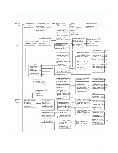
罗斯蒙特8800D475菜单中英文对照

1 Overview综述1 Check Status状态检查2 Primary Purpose Variables主变量Shortcuts 快捷模式31 Device Information设备信息2 Configure Outputs组态输出3 Simulate Flow流量仿真4 Optimize DSP优化数字信号处理5 View Trends趋势图6 View Totalizer总量1 Device Information 设备信息2 Sensor传感器3 Jumpers and Swtiches跳线和开关1 Basic Setup基本组态2 Configure Display组态显示3 Optimize DSP优化数字信号处理1 Tag位号2 Manufacturer制造厂3 Model型号4 Final Assembly #装配号5 Device ID设备标识6 Date日期7 Descriptor描述符8 Message信息9 Revision Numbers版本号1 Universal Revision 通用版本2 Field Device Rev 现场设备版本3 Software Revision 软件版本4 Hardware Revision 硬件版本1 Initial Configuration初始组态2 Process Configuration 过程组态1 Guided Setup向导组态2 Configure 组态2 Manual Setup手动组态3 Output Configuration输出组态4 Signal Processing信号处理1 Reference K-factor参考K系数1 Transmitter Mode变送器模式2 Compensated K-补偿后K系数2 Process Fluid过程流体factor3 Set Process Fluid设置流体3 Upper Sensor Limit传感器上限4 Fixed Proc Temp固定的过程温度4 Lower Sensor Limit传感器下限5 Fixed Proc Density固定过程密度1 Analog Output模拟量输出6 Pipe I.D. 管道内径2 Pulse Output脉冲输出3 Set Variable Mapping建立变量分配7 Installation Effect安装影响4 Special Units特殊单位1 T/C Failure Mode温度传感器失败模式1 Set Damping阻尼2 Set Installation Effect安装影响3 Low Flow Cutoff 小流量切除4 Low-pass Corner Frequency低通角频率5 Trigger Level触发水平6 Restore Default Filters恢复出场滤波1 Wetted Material接液材料2 Flange Type法兰类型3 Meter Body S/N仪表系列号4 Body # Suffix腔体后缀5 Meter Body #仪表体号1 Set Pipe I.D. 设置管道内径2 Set Process Temperature 设置介质温度3 Set Fixed Density设置固定密度4 Set Density Ratio设置密度比1 Sensor传感器2 Variable Mapping变量分配3 Process过程情况4 Outputs输出5 Signal Processing信号处理6 Display显示7 Communications通讯8 Device Information设备信息1 Process过程情况2 Flow Sensor流量传感器3 Temperature Sensor温度传感器4 Meter Body仪表本体1 Variable Mapping变量分配2 Process Variable Units过程变量单位3 Special Units特殊单位1 Primary Variable主变量2 2nd Variable第二变量3 3rd Variable第三变量4 4th Variable第四变量5 Set VariableMapping建立变量分配1 Volume Flow Units体积流量单位2 Velocity Flow Units速度流量单位3 Vel Measure Base速度测量基值4 Mass Flow Units质量流量单位5 Elec Temp Units电路板温度单位6 Proc Density Units过程密度单位1 Base Volume Unit基本体积单位2 Base Time Unit基本时间单位3 Spec Volume Unit特殊体积单位4 Conversion #转换系数5 Special 罗斯蒙特8800D涡街流量计HART475通讯器菜单树(中英)_文档下载https:///bd916d2d29e15d999d9633fe5.html Flow Unit特殊流量单位1 Polling Address轮询地址2 Burst Mode广播模式3 Burst Option广播选项4 Burst Variables广播变量1 Process Conditions过程条件2 Base Conditions 标准条件3 Density/Density Ratio密度/密度比1 Analog Output模拟量输出2 Pulse Output频率输出3 Totalizer总量1 Fixed Proc Density固定过程密2 Density Ratio密度比1 Density Ratio密度比2 Set Denisty Ratio建立密度比1 Process Variables过程变量2 Mapped Variables已分配变量3 Flow流量4 Frequency频率5 Diagnostics诊断1 Signal Strength号强度2 Volume Flow体积流量3 Shedding Frequency发生体频率4 Shed Freq at URV发生体频率上限5 Filter Settings滤波设置6 Damping阻尼1 Flow Rate流量2 Flow Unit流量单位3 Upper Range Value流量上限4 Lower Range Value流量下限5 Sensor Limits传感器测量范围6 Minimum Span最小允许量程7 Flow Damping流量阻尼1 Off关2 Direct (Shedding) 直接(发生体)3 Scaled Volumetric与体积流量关系4 Scaled Velocity与速度流量关系5 Scaled Mass与质量流量关系1 Total总量2 Totalizer Control总量控制3 Totalizer Config总量组态1 Optimize DSP优化数字信号处理2 Manual Filter Adjust手动滤波调整3 LFC Response小流量切除响应4 Restore Default Filters恢复到出场滤波值1 Signal Strength信号强度2 Volume Flow体积流量3 Low Flow Cutoff小流量切除4 Low-pass Corner Frequency低通角频率5 Trigger Level触发水平3 Service Tools 服务工具1 Device Alerts设备报警2 Variables变量3 Trends趋势图4 Maintenance维护5 Simulate仿真1 Volume Flow体积流量2 Velocity Flow速度流量3 Mass Flow质量流量4 Shedding Frequency发生体频率5 Pulse Frequency脉冲频率6 Signal Strength信号强度7 Electronics Temp电路板温度1 Signal Strength Gauge信号强度计量2 Signal Strength信号强度3 Elec Temp Gauge电路板温度计量4 Electronics Temp电路板温度5 Min Electronics Temp最低电路板温度6 Max Electronics Temp最高电路板温度1 Self Test自测试2 Reset Transmitter变送器3 Flow Simulation流量仿真1 Meter Verification仪表查证2 Signal Processing信号处理3 Analog Calibration模拟校准 1 Flow Simulation流量仿真2 Analog Output模拟量输出3 Pulse Output脉冲输出1 Flow Rate流量2 Shedding Frequency发生体频率3 Simulate Flow流量仿真4 Enable Normal Flow正常流量5 Current Mode当前模式1 Analog Output模拟量输出2 Percent of Range百分比范围3 Flow Rate流量4 Upper Range Value上限5 Lower Range Value下限6 Loop Test环路测试1 Pulse Frequency脉冲频率2 Pulse Output Mode脉冲输出范围3 Pulse Scaling脉冲范围4 Pulse Loop Test脉冲测试1 Analog Output模拟量输出2 Percent of Range百分比范围3 Flow Rate流量4 Upper Range Value上限5 Lower Range Value下限6 Analog Trim模拟输出修正7 Scaled Analog Trim模拟量全范围修正8 Restore FactoryCalibration恢复出厂校正。
8800D_475-375 菜单树(中文翻译版-xxx翻译,仅供参考)
传感器 1.工艺 2.流量传感器 3.温度传感器 4.表体
蓝色文本= 方法 红色文本 =只读
通信 1.轮询地址 2.突发模式 3.突发选项 4.突发变量
变量映像 1.变量映像 2.过程变量单位 3.特殊单位
突发变量 1.突发位置0 2.突发位置1 3.突发位置2 4.突发位置3 5.突发变量转换 标识 1.位号:FT-100 2.制造厂:罗斯蒙特 3.型号:8800D 4.最终组装编号 5.设备ID:123456 6.写保护:关 信息 1.日期 2.描述 3.信息 版本号 1.通用版本号:5 2.现场设备号:2 3.软件版本号:3 4.硬件版本号:1
(无标题) 报警名称 描述 操作建议 有些窗口可以同时显示报警1-4 (无标题) 图像 有些窗口可以同时显示报警1-4 过程变量 1.“主变量标题”指示表 2.“数值”:XX.XXX UOM M 3.“累积值”:XXXX.XX UOM 4.介质温度指示表 5.介质温度:XX.XXX UOM 6.计算介质密度指示表 7.介质密度:XX.XXXUOM 标题与变量名一致(体积流量, 速度流量,质量流量或介质温度)。 1,4&6以指示表图像显示。 4&5才可显示。 仅当变送器模式=带温度传感器时, 流体介质=温度补偿饱和蒸汽时, 仅当变送器模式=带温度传感器, 6&7才可显示。 映射变量 1.“主变量标题”指示表 2.“数值”:XX.XXXUOM 3.“2级变量标题”指示表 4.“数值”:XX.XXXUOM 5.“3级变量标题”指示表 6.“数值”:XX.XXXUOM 7.“4级变量标题”指示表 8.“数值”:XX.XXXUOM 标题应与变量名一致 1,3,5&7以指示表图像显示 若变量=累积流量,将以奇数行显示累积量, 有“数值” 累积值/单位则显示在偶数行(没有指示表), 流量 1.体积流量指示表 2.体积流量:XX.XXXUOM 3.速度流量指示表 4.速度流量:XX.XXXUOM 5.质量流量指示表 6.质量流量:XX.XXXUOM 7.累积流量:XX.XXXUOM 1&3,5以指示表图像显示
罗斯蒙特涡街流量计8800D 说明书
• 减少项目风险 - 缩径型涡街流量计和标准涡街 流量计有相同的法兰面对面尺寸。这样可以使 用任一种流量计而不影响管线布局。
• 缩径型涡街流量计为法兰型,从 1 到 12 英寸, 不锈钢和镍合金 C 材质。
• 具有基金会现场总线功能。
(1) 我们已经知道过程温度和管道内径 ID 会影响到 K 系数, 8800D 型软件通过补偿 K 系数来自动纠正这些影响。
4
产品样本
00813-0100-4004-C, Rev BA 2006 年 3 月
8800D 型
规格
下列规格适用于 8800D 型 , 8800DR 型和 8800DD 型,加注释的 除外。
自诊断
变送器自动进行连续的自诊断。用户能进行变送器数 字信号的在线测试,可用先进的仿真自诊断功能,通 过软件中流量信号发生器远程鉴定电子部件。传感器 信号强度可用来检查过程流量信号并提供滤波器设置 的相关信息。
产品样本
00813-0100-4004-C, Rev BA 2006 年 3 月
基金会现场总线功能块
• 全铸造和无阻塞设计消除了腔体内的孔和垫 圈。
• 专利技术的自适应数字信号处理 (ADSP) 提供 了优越的抗振动性能。
• 独特的隔离式传感器设计允许传感器在线更 换,而不用破坏工艺密封。
• 通过设备自诊断简化了故障处理。
8800D 型
内容提要
规格 . . . . . . . . . . . . . . . . . . . . . . . . . . . . . . . . . . . . . . . . . . . . . . . . . . . . . . . . . . . . . . . . . . 5 产品认证 . . . . . . . . . . . . . . . . . . . . . . . . . . . . . . . . . . . . . . . . . . . . . . . . . . . . . . . . . . . . . 18 尺寸图 . . . . . . . . . . . . . . . . . . . . . . . . . . . . . . . . . . . . . . . . . . . . . . . . . . . . . . . . . . . . . . . 21 订购信息 . . . . . . . . . . . . . . . . . . . . . . . . . . . . . . . . . . . . . . . . . . . . . . . . . . . . . . . . . . . . . 39 组态数据表 . . . . . . . . . . . . . . . . . . . . . . . . . . . . . . . . . . . . . . . . . . . . . . . . . . . . . . . . . . . 43
8800D系列涡街流量计样本

产品样本00813-0600-4004, Rev DA 2007 年 3 月/rosemount 8800D 型HART®和基金会™现场总线协议•可选的多变量输出和饱合蒸汽温度补偿的质量流量功能。
•有夹持型、法兰型、双传感器型,缩径型和高压型。
•唯一一家具有缩径型涡街流量计厂家,这种涡街流量计扩大了流量测量范围,减少了安装成本,并使项目风险减到最小程度。
•全铸造和无阻塞设计消除了腔体内的孔和垫圈。
•专利技术的自适应数字信号处理 (ADSP) 提供了优越的抗振动性能。
•独特的隔离式传感器设计允许传感器在线更换,而不用破坏工艺密封。
•通过设备自诊断简化了故障处理。
•通过内部信号发生器简化了仪表自校验。
内容提要规格. . . . . . . . . . . . . . . . . . . . . . . . . . . . . . . . . . . . . . . . . . . . . . . . . . . . . . . . . . . . . . . . . . 6产品认证 . . . . . . . . . . . . . . . . . . . . . . . . . . . . . . . . . . . . . . . . . . . . . . . . . . . . . . . . . . . . . 19尺寸图 . . . . . . . . . . . . . . . . . . . . . . . . . . . . . . . . . . . . . . . . . . . . . . . . . . . . . . . . . . . . . . . 26订购信息 . . . . . . . . . . . . . . . . . . . . . . . . . . . . . . . . . . . . . . . . . . . . . . . . . . . . . . . . . . . . . 44 8800D 组态数据表. . . . . . . . . . . . . . . . . . . . . . . . . . . . . . . . . . . . . . . . . . . . . . . . . . . . . . 48 8800D 型涡街流量计产品样本00813-0600-4004, Rev DA2007 年 3 月28800D 型8800D 型提供可靠性•罗斯蒙特可靠性 - 8800D 型涡街流量计无引压管、孔和垫圈,提高了可靠性。
罗斯蒙特8800D涡街流量计HART菜单
Status 1 Device Status: Good 2 Communications: Polled
Revision Numbers 1 Universal Revision: 5 2 Field Device Revision: 2 3 Software Revision: 3 4 Hardware Revision: 1 Process 1 Transmitter Mode 2 Process Fluid 3 Fixed Proc Temp 4 Fixed Proc Density 5 Pipe I.D. 6 Installation Effect Flow Sensor 1 Reference K Factor 2 Compensated K Factor 3 Upper Sensor Limit 4 Lower Sensor Limi NOTE: Limits are only displayed if PV = Flow Temperature Sensor 1 T/C Failure Mode 2 Upper Sensor Limit 3 Lower Sensor Limi NOTE: Limits are only displayed if PV = Temperatur Meter Body 1 Wetted Material 2 Flange Type 3 Meter Body Serial Number 4 Body # Suffix 5 Meter Body #: 123456A
Process Conditions 1 Fixed Proc Temp 2 Change Proc Temp Units 3 Proc Pressure (abs) 4 Change Proc Pressure (abs) 5 Proc Compressibility Base Conditions 1 Base Temperature 2 Change Base Temp 3 Base Pressure 4 Change Base Pressure 5 Base Compressibility Density/Density Ratio 1 Fixed Proc Density 2 Density Ratio
罗斯蒙特8800涡街流量计-选型计算书
0.09
0.03
0.10
0.03
0.00
0.00
0.00
0.00
1453.99 1084.15
0.00 0.00 163223.00 4.68
2752.70 2112.27
0.00 0.00 205924.00 4.30
Байду номын сангаас
1453.99 1084.15
0.00 0.00 163223.00 4.68
2752.70 2112.27
0.00 0.00 205924.00 4.30
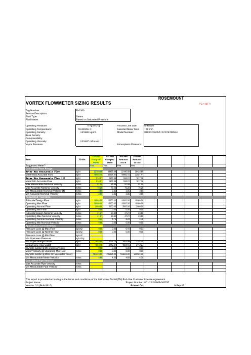
This report is provided according to the terms and conditions of the Instrument Toolkit(TM) End-Use Customer License Agreement.
150 mm Flanged/
Wafer Yes
200 mm Flanged/
Wafer Yes
200 mm Reducer
8 to 6 Yes
250 mm Reducer 10 to 8 Yes
22190.58 18492.15
934.01 934.01 91.44 76.20
3.85 3.85
38425.69 32021.41 1617.36 1617.36
Project Name :
Project Number: 001-20150908-000797
Version: 3.0 (Build191G)
Printed On:
9-Sep-15
PG 1 OF 1
罗斯蒙特8800D系列涡街流量计

目录
订购信息 . . . . . . . . . . . . . . . . . . . . . . . . . . . . . . . . . . . . . . . . . . . . . . . . . . . . . . . . . . . . . . . . . . . . . . . 7 规格 . . . . . . . . . . . . . . . . . . . . . . . . . . . . . . . . . . . . . . . . . . . . . . . . . . . . . . . . . . . . . . . . . . . . . . . . . 12 典型流量范围 . . . . . . . . . . . . . . . . . . . . . . . . . . . . . . . . . . . . . . . . . . . . . . . . . . . . . . . . . . . . . . . . . . 17 产品认证 . . . . . . . . . . . . . . . . . . . . . . . . . . . . . . . . . . . . . . . . . . . . . . . . . . . . . . . . . . . . . . . . . . . . . . .27 尺寸图 . . . . . . . . . . . . . . . . . . . . . . . . . . . . . . . . . . . . . . . . . . . . . . . . . . . . . . . . . . . . . . . . . . . . . . . . 32
每款夹持式流量计都配备定位环,27 确保表体与邻接管线 正确对中。
罗斯蒙特8800D涡街流量计HART475通讯器菜单树(中英)(1)
1 Overview综述2Configure组态3 Service Tools服务工具1 Check Status状态检查 1 Device Information设备信息 1 Device Information设备信息 1 Tag位号 1 Universal Revision 通用版本2 Primary Purpose 2 Configure Outputs组态输出 2 Sensor传感器 2 Manufacturer制造厂 2 Field Device Rev 现场设备版本Variables主变量 3 Simulate Flow流量仿真3Jumpers and Swtiches跳线和开关 3 Model型号 3 Software Revision 软件版本3Shortcuts快捷模式4 Optimize DSP优化数字信号处理 4 Final Assembly #装配号 4 Hardware Revision 硬件版本1 Basic Setup基本组态5 View Trends趋势图 5 Device ID设备标识6 View Totalizer总量 2 Configure Display组态显示 6 Date日期3 Optimize DSP优化数字信号7 Descriptor描述符处理8 Message信息1 Set Pipe I.D.设置管道内径9 Revision Numbers版本号1 Initial Configuration初始组态2 Set Process Temperature设1 Reference K-factor参考K系数2 Process Configuration过程组置介质温度 1 Transmitter Mode变送器模式2 Compensated K-补偿后K系数态3 Set Fixed Density设置固定密度 2 Process Fluid过程流体factor4 Set Density Ratio设置密度比1 Guided Setup向导组态 3 Set Process Fluid设置流体3 Output Configuration输出组态 3 Upper Sensor Limit传感器上限2 Manual Setup手动组态 4 Signal Processing信号处理1 Analog Output模拟量输出4 Fixed Proc Temp固定的过程温度4 Lower Sensor Limit传感器下限5 Fixed Proc Density固定过程密度2 Pulse Output脉冲输出 6 Pipe I.D.管道内径3 Set Variable Mapping建立变量分配7 Installation Effect安装影响4 Special Units特殊单位1 T/C Failure Mode温度传感器失败模式1 Set Damping阻尼 1 Wetted Material接液材料2 Set Installation Effect安装影响 2 Flange Type法兰类型 1 Volume Flow Units体积流量单位3 Low Flow Cutoff小流量切除 3 Meter Body S/N仪表系列号 2 Velocity Flow Units速度流量单位4 Low-pass Corner Frequency 4 Body # Suffix腔体后缀 3 Vel Measure Base速度测量基值低通角频率 5 Meter Body #仪表体号 4 Mass Flow Units质量流量单位5 Trigger Level触发水平 5 Elec Temp Units电路板温度单位6 Restore Default Filters恢复出场 1 Primary Variable主变量 6 Proc Density Units过程密度单位滤波2 2nd Variable第二变量1 Process过程情况1 Sensor传感器 3 3rd Variable第三变量 1 Base Volume Unit基本体积单位2 Flow Sensor流量传感器2 Variable Mapping变量分配 4 4th Variable第四变量 2 Base Time Unit基本时间单位3 Temperature Sensor温度传感器5 Set Variable3 Process过程情况 3 Spec Volume Unit特殊体积单位4 Meter Body仪表本体4 Outputs输出Mapping建立变量分配 4 Conversion #转换系数5 Special Flow Unit特殊流量单位5 Signal Processing信号处理1 Variable Mapping变量分配6 Display显示2 Process Variable Units过程变量单位7 Communications通讯3 Special Units特殊单位8 Device Information设备信息1 Process Conditions过程条件 1 Fixed Proc Density固定过程密 1 Density Ratio密度比2 Density Ratio密度比 2 Set Denisty Ratio建立密度比1 Polling Address轮询地址2 Base Conditions标准条件2 Burst Mode广播模式3 Density/Density Ratio密度/密度3 Burst Option广播选项比 1 Flow Rate流量 1 Off关4 Burst Variables广播变量 1 Analog Output模拟量输出 2 Flow Unit流量单位 2 Direct (Shedding)直接(发生体)2 Pulse Output频率输出3 Upper Range Value流量上限 3 Scaled Volumetric与体积流量关系3 Totalizer总量4 Lower Range Value流量下限 4 Scaled Velocity与速度流量关系1 Process Variables过程变量 5 Sensor Limits传感器测量范围 5 Scaled Mass与质量流量关系6 Minimum Span最小允许量程2 Mapped Variables已分配变量 1 Signal Strength号强度7 Flow Damping流量阻尼3 Flow流量 2 Volume Flow体积流量4 Frequency频率 3 Shedding Frequency发生体频率1 Total总量5 Diagnostics诊断 4Shed Freq at URV发生体频率上限2 Totalizer Control总量控制5 Filter Settings滤波设置3 Totalizer Config总量组态6 Damping阻尼1 Optimize DSP优化数字信号处理1 Device Alerts设备报警 1 Volume Flow体积流量2 Manual Filter Adjust手动滤波调整1 Signal Strength信号强度2 Variables变量 2 Velocity Flow速度流量 1 Signal Strength Gauge信号强度计量3 LFC Response小流量切除响应2 Volume Flow体积流量3 Trends趋势图 3 Mass Flow质量流量 2 Signal Strength信号强度4 Restore Default Filters恢复到出场3 Low Flow Cutoff小流量切除4 Maintenance维护 4 Shedding Frequency发生体频率 3 Elec Temp Gauge电路板温度计量滤波值4 Low-pass Corner5 Simulate仿真 5 Pulse Frequency脉冲频率 4 Electronics Temp电路板温度Frequency低通角频率6 Signal Strength信号强度 5 Min Electronics Temp最低电路板温度1 Flow Rate流量 5 Trigger Level触发水平7 Electronics Temp电路板温度 6 Max Electronics Temp最高电路板温度2 Shedding Frequency发生体频率1 Self Test自测试3 Simulate Flow流量仿真1 Analog Output模拟量输出1 Meter Verification仪表查证 4 Enable Normal Flow正常流量2 Signal Processing信号处理 2 Reset Transmitter变送器 5 Current Mode当前模式 2 Percent of Range百分比范围3 Analog Calibration模拟校准 3 Flow Simulation流量仿真 3 Flow Rate流量4 Upper Range Value上限1 Flow Simulation流量仿真5 Lower Range Value下限1 Pulse Frequency脉冲频率6 Analog Trim模拟输出修正2 Analog Output模拟量输出1 Analog Output模拟量输出7 Scaled Analog Trim模拟量全范围修正3 Pulse Output脉冲输出 2 Pulse Output Mode脉冲输2 Percent of Range百分比范围8 Restore Factory出范围3 Flow Rate流量 3 Pulse Scaling脉冲范围Calibration恢复出厂校正4 Upper Range Value上限 4 Pulse Loop Test脉冲测试5 Lower Range Value下限6 Loop Test环路测试taoyu。
- 1、下载文档前请自行甄别文档内容的完整性,平台不提供额外的编辑、内容补充、找答案等附加服务。
- 2、"仅部分预览"的文档,不可在线预览部分如存在完整性等问题,可反馈申请退款(可完整预览的文档不适用该条件!)。
- 3、如文档侵犯您的权益,请联系客服反馈,我们会尽快为您处理(人工客服工作时间:9:00-18:30)。
常规组态流程:A 确认变送器模式:有热电偶(型号中有MTA)或者无热电偶
B 设置介质类型:液体、气体/蒸汽、还是温度补偿的饱和蒸汽(仅针对有MTA选项的仪表)
C 校对仪表K系数:是否与表体标示一致。
D 变量分配:设置输出类型是质量流量还是体积流量
E F 单位与量程:设置4与20mA对应值。
G 如有必要,进行滤波设置
H 回路测试:仿真输出并与上位机显示做比对。
8800D 涡街流量计H a r t 菜单树 (D e v v 2, D D v 3)
设置过程状况:若输出质量流量,必须设置密度值(MTA选项且介质是温度补偿饱和蒸汽的不需要);若输出标方,务必设置正确过程温度压力和标准温度压力以计算密度比;如果输出工况体积流量,则需要设置过程温度。