防火墙配置实例
防火墙gre隧道配置实例

防火墙gre隧道配置实例
防火墙GRE隧道的配置实例如下:
1. 拓扑图:北京总公司与上海分公司通过广域网连接,使用一个三层交换机模拟广域网,并使用两个H3C的防火墙进行GRE接入。
2. 配置广域网通信:首先,在交换机上创建两个VLAN,分别是VLAN 10和VLAN 20,并将相应的端口加入到相应的VLAN中。
然后,在VLAN 10上配置IP地址。
3. 配置防火墙:在两个防火墙(FW1和FW2)上配置GRE隧道,使它们能够通过Internet相互通信。
4. 测试:测试北京总公司与上海分公司之间的内网通信是否正常。
请注意,上述配置是一个简化的示例,实际配置可能因网络环境、设备型号和需求而有所不同。
在进行实际配置之前,建议仔细阅读设备文档并咨询专业人士。
防火墙透明模式典型配置举例
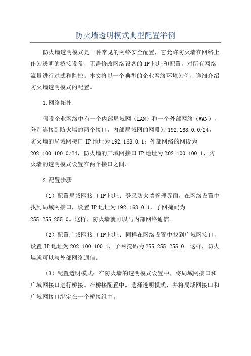
防火墙透明模式典型配置举例防火墙透明模式是一种常见的网络安全配置,它允许防火墙在网络上作为透明的桥接设备,无需修改网络设备的IP地址和配置,对所有网络流量进行过滤和监控。
本文将以一个典型的企业网络环境为例,详细介绍防火墙透明模式的配置。
1.网络拓扑假设企业网络中有一个内部局域网(LAN)和一个外部网络(WAN),分别连接到防火墙的两个接口。
内部局域网的网段为192.168.0.0/24,防火墙的局域网接口IP地址为192.168.0.1;外部网络的网段为202.100.100.0/24,防火墙的广域网接口IP地址为202.100.100.1、防火墙的透明模式设置在两个接口之间。
2.配置步骤(1)配置局域网接口IP地址:登录防火墙管理界面,在网络设置中找到局域网接口,设置IP地址为192.168.0.1,子网掩码为255.255.255.0。
这样,防火墙就可以与内部网络通信。
(2)配置广域网接口IP地址:同样在网络设置中找到广域网接口,设置IP地址为202.100.100.1,子网掩码为255.255.255.0。
这样,防火墙就可以与外部网络通信。
(3)配置透明模式:在防火墙的透明模式设置中,将局域网接口和广域网接口进行桥接。
在桥接配置中,选择透明模式,并将局域网接口和广域网接口绑定在一个桥接组中。
(4)配置ACL(访问控制列表):通过ACL可以定义防火墙的过滤规则,控制允许和禁止的流量。
例如,可以设置允许内部网络对外访问的规则,禁止特定IP地址的访问规则等。
在防火墙管理界面的策略设置中,创建相应的ACL规则。
(5)配置NAT(网络地址转换):NAT可以将内部网络的私有IP地址映射为公共IP地址,实现内部网络对外部网络的访问。
在防火墙的NAT设置中,配置相应的NAT规则。
(6)配置日志功能:在防火墙中启用日志功能,记录所有的网络流量和安全事件。
可以将日志信息发送到指定的日志服务器,方便网络管理员进行监控和分析。
H3C防火墙配置实例

本文为大家介绍一个H3C防火墙的配置实例,配置内容包括:配置接口IP地址、配置区域、配置NAT地址转换、配置访问策略等,组网拓扑及需求如下。
1、网络拓扑图2、配置要求1)防火墙的E0/2接口为TRUST区域,ip地址是:192.168.254.1/29;2)防火墙的E1/2接口为UNTRUST区域,ip地址是:202.111.0.1/27;3)内网服务器对外网做一对一的地址映射,192.168.254.2、192.168.254.3分别映射为202.111.0.2、202.111.0.3;4)内网服务器访问外网不做限制,外网访问内网只放通公网地址211.101.5.49访问192.168.254.2的1433端口和192.168.254.3的80端口。
3、防火墙的配置脚本如下<H3CF100A>dis cur#sysname H3CF100A#super password level 3 cipher 6aQ>Q57-$.I)0;4:\(I41!!!#firewall packet-filter enablefirewall packet-filter default permit#insulate##firewall statistic system enable#radius scheme systemserver-type extended#domain system#local-user net1980password cipher ######service-type telnetlevel 2#aspf-policy 1detect h323detect sqlnetdetect rtspdetect httpdetect smtpdetect ftpdetect tcpdetect udp##acl number 3001description out-insiderule 1 permit tcp source 211.101.5.49 0 destination 192.168.254.2 0 destination-port eq 1433 rule 2 permit tcp source 211.101.5.49 0 destination 192.168.254.3 0 destination-port eq www rule 1000 deny ipacl number 3002description inside-to-outsiderule 1 permit ip source 192.168.254.2 0rule 2 permit ip source 192.168.254.3 0rule 1000 deny ip#interface Aux0async mode flow#interface Ethernet0/0shutdown#interface Ethernet0/1shutdown.#interface Ethernet0/2speed 100duplex fulldescription to serverfirewall packet-filter 3002 inboundfirewall aspf 1 outbound#interface Ethernet0/3shutdown#interface Ethernet1/0shutdown#interface Ethernet1/1shutdown#interface Ethernet1/2speed 100duplex fulldescription to internetfirewall packet-filter 3001 inboundfirewall aspf 1 outboundnat outbound static#interface NULL0#firewall zone localset priority 100#firewall zone trustadd interface Ethernet0/2set priority 85#firewall zone untrustadd interface Ethernet1/2set priority 5#firewall zone DMZadd interface Ethernet0/3set priority 50#.firewall interzone local trust#firewall interzone local untrust#firewall interzone local DMZ#firewall interzone trust untrust#firewall interzone trust DMZ#firewall interzone DMZ untrust#ip route-static 0.0.0.0 0.0.0.0 202.111.0.30 preference 60 #user-interface con 0user-interface aux 0user-interface vty 0 4authentication-mode scheme#return。
思科ASA5505防火墙配置成功实例

配置要求:1、分别划分inside(内网)、outside(外网)、dmz(安全区)三个区域。
2、内网可访问外网及dmz内服务器(web),外网可访问dmz内服务器(web)。
3、Dmz服务器分别开放80、21、3389端口。
说明:由于防火墙许可限制“no forward interface Vlan1”dmz内服务器无法访问外网。
具体配置如下:希望对需要的朋友有所帮助ASA Version 7.2(4)!hostname asa5505enable password tDElRpQcbH/qLvnn encryptedpasswd 2KFQnbNIdI.2KYOU encryptednames!interface Vlan1nameif outsidesecurity-level 0ip address 外网IP 外网掩码!interface Vlan2nameif insidesecurity-level 100ip address 192.168.1.1 255.255.255.0!interface Vlan3no forward interface Vlan1nameif dmzsecurity-level 50ip address 172.16.1.1 255.255.255.0!interface Ethernet0/0description outside!interface Ethernet0/1description insideswitchport access vlan 2!interface Ethernet0/2description dmzswitchport access vlan 3!interface Ethernet0/3description insideswitchport access vlan 2!interface Ethernet0/4shutdown!interface Ethernet0/5shutdown!interface Ethernet0/6shutdown!interface Ethernet0/7shutdown!ftp mode passiveobject-group service outside-to-dmz tcpport-object eq wwwport-object eq ftpport-object eq 3389access-list aaa extended permit tcp any host 外网IP object-group outsid e-to-dmzaccess-list bbb extended permit tcp host 172.16.1.2 192.168.1.0 255.255. 255.0 object-group outside-to-dmzpager lines 24mtu outside 1500mtu inside 1500mtu dmz 1500icmp unreachable rate-limit 1 burst-size 1asdm image disk0:/asdm-524.binno asdm history enablearp timeout 14400global (outside) 1 interfaceglobal (dmz) 1 172.16.1.10-172.16.1.254 netmask 255.255.255.0nat (inside) 1 192.168.1.0 255.255.255.0nat (dmz) 1 172.16.1.0 255.255.255.0alias (inside) 221.203.36.86 172.16.1.2 255.255.255.255static (dmz,outside) tcp interface www 172.16.1.2 www netmask 255.255.2 55.255 dnsstatic (dmz,outside) tcp interface ftp 172.16.1.2 ftp netmask 255.255.2 55.255 dnsstatic (dmz,outside) tcp interface 3389 172.16.1.2 3389 netmask 255.255. 255.255dnsstatic (inside,dmz) 172.16.1.2 192.168.1.0 netmask 255.255.255.255 dns access-group aaa in interface outsideaccess-group bbb in interface dmzroute outside 0.0.0.0 0.0.0.0 外网网关 1timeout xlate 3:00:00timeout conn 1:00:00 half-closed 0:10:00 udp 0:02:00 icmp 0:00:02timeout sunrpc 0:10:00 h323 0:05:00 h225 1:00:00 mgcp 0:05:00 mgcp-pat 0:05:00timeout sip 0:30:00 sip_media 0:02:00 sip-invite 0:03:00 sip-disconnect 0:02:00timeout sip-provisional-media 0:02:00 uauth 0:05:00 absoluteno snmp-server locationno snmp-server contactsnmp-server enable traps snmp authentication linkup linkdown coldstart telnet timeout 5ssh timeout 5console timeout 0!class-map inspection_defaultmatch default-inspection-traffic!!policy-map type inspect dns preset_dns_mapparametersmessage-length maximum 512policy-map global_policyclass inspection_defaultinspect dns preset_dns_mapinspect ftpinspect h323 h225inspect h323 rasinspect netbiosinspect rshinspect rtspinspect skinnyinspect esmtpinspect sqlnetinspect sunrpcinspect tftpinspect sipinspect xdmcpinspect http!service-policy global_policy globalprompt hostname contextCryptochecksum:9d2a6010d4fc078cf026f98dcec96007 : endasa5505(config)#。
H3C Firewall 配置实例
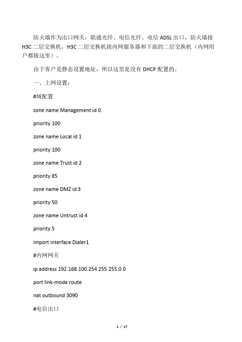
防火墙作为出口网关,联通光纤、电信光纤、电信ADSL出口,防火墙接H3C二层交换机,H3C二层交换机接内网服务器和下面的二层交换机(内网用户都接这里)。
由于客户是静态设置地址,所以这里是没有DHCP配置的。
一、上网设置:#域配置zone name Management id 0priority 100zone name Local id 1priority 100zone name Trust id 2priority 85zone name DMZ id 3priority 50zone name Untrust id 4priority 5import interface Dialer1#内网网关ip address 192.168.100.254 255.255.0.0port link-mode routenat outbound 3090#电信出口port link-mode routeip address 219.137.182.2xx 255.255.255.248nat outbound 2000 address-group 1#联通出口port link-mode routeip address 218.107.10.xx 255.255.255.248nat outbound 2000 address-group 2#PPPOE电信ADSLport link-mode routepppoe-client dial-bundle-number 1#设定拨号访问组的拨号控制列表dialer-rule 1 ip permit#PPPOE配置interface Dialer1nat outbound 2000link-protocol pppppp chap userppp chap password cipher$c$3$cft8cT2sYcO4XYUDKRgfw0R0HOSTSDh69HbN KCf9IdG。
华为USG5500防火墙配置实验一

华为USG5500防火墙配置实验1、实验拓扑内网:192.168.0.0/24外网:192.168.1.0/24其他设备地址规划如图,按照拓扑图搭建网络,并配置设备地址2、具体配置命令AR1<Huawei>system-view[Huawei]sysname AR1[AR1]interface g0/0/0[AR1-GigabitEthernet0/0/0]ip address 192.168.0.150 24[AR1-GigabitEthernet0/0/0]quit 退出[AR1]ip route-static 0.0.0.0 0.0.0.0 192.168.0.1 配置默认路由AR1开启Telnet服务[AR1]user-interface vty 0 4 开启远程线程[AR1-ui-vty0-4]au[AR1-ui-vty0-4]authentication-mode password 认证方式为password Please configure the login password (maximum length 16):888 登录密码 [AR1-ui-vty0-4]user privilege level 3 设置用户等级[AR1-ui-vty0-4]AR2<Huawei>system-view[Huawei]sysname AR2[AR2]interface g0/0/0[AR2-GigabitEthernet0/0/0]ip add[AR2-GigabitEthernet0/0/0]ip address 192.168.1.150 24[AR2-GigabitEthernet0/0/0]q[AR1]ip route-static 0.0.0.0 0.0.0.0 192.168.1.1AR2配置TelnetAR2]us[AR2]user-interface v[AR2]user-interface vty 0 4[AR2-ui-vty0-4]au[AR2-ui-vty0-4]authentication-mode p[AR2-ui-vty0-4]authentication-mode passwordPlease configure the login password (maximum length 16):666 或者[AR2-ui-vty0-4]set authentication password cipher 666[AR2-ui-vty0-4]user privilege level 3[AR2-ui-vty0-4]q防火墙配置:The device is running!<SRG>system-view[SRG]sysname FW1[FW1]interface g0/0/0[FW1-GigabitEthernet0/0/0]ip add 192.168.0.1 24Warning: Address already exists! 默认接口地址已经存在,不用管[FW1-GigabitEthernet0/0/0]q[FW1]interface g0/0/1[FW1-GigabitEthernet0/0/1]ip add 192.168.1.1 24[FW1-GigabitEthernet0/0/1]q[FW1]display zone 显示区域配置localpriority is 100#trustpriority is 85interface of the zone is (1):GigabitEthernet0/0/0#untrustpriority is 5interface of the zone is (0):#dmzpriority is 50interface of the zone is (0):#[FW1][FW1]firewall zone name outside 创建一个名字为outside的区域[FW1-zone-outside]set priority 30 设置安全等级为30[FW1-zone-outside]q[FW1]firewall zone name inside[FW1-zone-inside]set priority 90[FW1-zone-inside]q[FW1]display zone[FW1]firewall zone outside 进入outside区域,把接口g0/0/1接入该区域[FW1-zone-outside]add interface GigabitEthernet 0/0/1[FW1-zone-outside]display this 显示当前的配置#firewall zone name outsideset priority 30add interface GigabitEthernet0/0/1#return[FW1-zone-outside]q[FW1]display policy all 查看策略policy zone local#policy zone trust#policy zone untrust#policy zone dmz#policy zone outside#policy zone inside#policy interzone local trust inboundfirewall default packet-filter is permit#policy interzone local trust outboundfirewall default packet-filter is permit#policy interzone local untrust inboundfirewall default packet-filter is deny#policy interzone local untrust outbound firewall default packet-filter is permit #policy interzone local dmz inboundfirewall default packet-filter is deny#policy interzone local dmz outboundfirewall default packet-filter is permit #policy interzone local outside inboundfirewall default packet-filter is deny#policy interzone local outside outbound firewall default packet-filter is permit #policy interzone local inside inboundfirewall default packet-filter is deny#policy interzone local inside outboundfirewall default packet-filter is permit #policy interzone trust untrust inboundfirewall default packet-filter is deny#policy interzone trust untrust outbound firewall default packet-filter is deny#policy interzone trust dmz inboundfirewall default packet-filter is deny#policy interzone trust dmz outboundfirewall default packet-filter is deny#policy interzone trust outside inboundfirewall default packet-filter is deny#policy interzone trust outside outbound firewall default packet-filter is deny#policy interzone inside trust inboundfirewall default packet-filter is deny#policy interzone inside trust outboundfirewall default packet-filter is deny#policy interzone dmz untrust inboundfirewall default packet-filter is deny#policy interzone dmz untrust outboundfirewall default packet-filter is deny#policy interzone outside untrust inboundfirewall default packet-filter is deny#policy interzone outside untrust outboundfirewall default packet-filter is deny#policy interzone inside untrust inboundfirewall default packet-filter is deny#policy interzone inside untrust outboundfirewall default packet-filter is deny#policy interzone dmz outside inboundfirewall default packet-filter is deny#policy interzone dmz outside outboundfirewall default packet-filter is deny#policy interzone inside dmz inboundfirewall default packet-filter is deny#policy interzone inside dmz outboundfirewall default packet-filter is deny#policy interzone inside outside inboundfirewall default packet-filter is deny#policy interzone inside outside outboundfirewall default packet-filter is deny#[FW1]创建策略放行outbound流量[FW1]policy interzone trust outside outbound 定义outbound流量 [FW1-policy-interzone-trust-outside-outbound]poli[FW1-policy-interzone-trust-outside-outbound]policy 1[FW1-policy-interzone-trust-outside-outbound-1]poli[FW1-policy-interzone-trust-outside-outbound-1]policy so[FW1-policy-interzone-trust-outside-outbound-1]policy source192.168.0.150 001:27:13 2016/11/15[FW1-policy-interzone-trust-outside-outbound-1]poli[FW1-policy-interzone-trust-outside-outbound-1]policy de[FW1-policy-interzone-trust-outside-outbound-1]policy destination any 01:27:25 2016/11/15[FW1-policy-interzone-trust-outside-outbound-1]ac[FW1-policy-interzone-trust-outside-outbound-1]action p[FW1-policy-interzone-trust-outside-outbound-1]action permit01:27:34 2016/11/15[FW1-policy-interzone-trust-outside-outbound-1][FW1-policy-interzone-trust-outside-outbound-1]q01:27:37 2016/11/15[FW1-policy-interzone-trust-outside-outbound][FW1-policy-interzone-trust-outside-outbound]q01:27:38 2016/11/15[FW1][FW1][FW1]dis[FW1]display po[FW1]display poli[FW1]display policy i[FW1]display policy interzone t[FW1]display policy interzone trust o[FW1]display policy interzone trust outside outbound01:27:55 2016/11/15policy interzone trust outside outboundfirewall default packet-filter is denypolicy 1 (0 times matched)action permitpolicy service service-set ippolicy source 192.168.0.0 mask 255.255.255.0policy source 192.168.0.150 0policy destination any[FW1]firewall packet-filter default permit interzone trust outside Warning:Setting the default packet filtering to permit poses security risks. Youare advised to configure the security policy based on the actual data flows. Are you sure you want to continue?[Y/N]y[FW1]dis[FW1]display policy interzone trust outside outbound01:28:23 2016/11/15policy interzone trust outside outboundfirewall default packet-filter is permitpolicy 1 (0 times matched)action permitpolicy service service-set ippolicy source 192.168.0.0 mask 255.255.255.0policy source 192.168.0.150 0policy destination any恢复默认值deny[FW1]firewall packet-filter default deny interzone trust outside [FW1]display policy interzone trust outside outbound01:32:06 2016/11/15policy interzone trust outside outboundfirewall default packet-filter is denypolicy 1 (0 times matched)action permitpolicy service service-set ippolicy source 192.168.0.0 mask 255.255.255.0policy source 192.168.0.150 0policy destination any用内网的路由Telnet AR2后,可以登录在防火墙查看会话状态[FW1]display firewall session table verbose00:58:32 2016/11/15Current Total Sessions : 2telnet VPN:public --> publicZone: trust--> outside TTL: 00:00:10 Left: 00:00:00Interface: GigabitEthernet0/0/1 NextHop: 192.168.1.150 MAC: 00-e0-fc-7a-0b-5a<--packets:18 bytes:867 -->packets:17 bytes:728192.168.0.150:49272-->192.168.1.150:23telnet VPN:public --> publicZone: trust--> outside TTL: 00:10:00 Left: 00:09:55Interface: GigabitEthernet0/0/1 NextHop: 192.168.1.150 MAC: 00-e0-fc-7a-0b-5a<--packets:16 bytes:725 -->packets:17 bytes:726192.168.0.150:49957-->192.168.1.150:23[FW1]如何允许外网的用户Telnet到内网的路由器[FW1]policy interzone trust outside inbound[FW1-policy-interzone-trust-outside-inbound]policy 1[FW1-policy-interzone-trust-outside-inbound-1]policy source 192.168.1.150 0[FW1-policy-interzone-trust-outside-inbound-1]policy destination 192.168.0.150 0[FW1-policy-interzone-trust-outside-inbound-1]policy service service-set telnet[FW1-policy-interzone-trust-outside-inbound-1]action permit验证试验效果。
防火墙配置案例
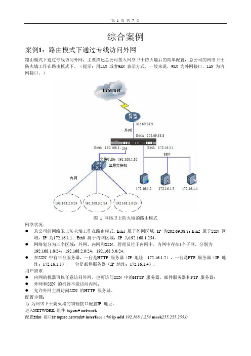
综合案例案例1:路由模式下通过专线访问外网路由模式下通过专线访问外网,主要描述总公司接入网络卫士防火墙后的简单配置,总公司的网络卫士防火墙工作在路由模式下。
(提示:用LAN 或者WAN 表示方式。
一般来说,WAN 为外网接口,LAN 为内网接口。
)图 1 网络卫士防火墙的路由模式网络状况:●总公司的网络卫士防火墙工作在路由模式。
Eth1 属于外网区域,IP 为202.69.38.8;Eth2 属于SSN 区域,IP 为172.16.1.1;Eth0 属于内网区域,IP 为192.168.1.254。
●网络划分为三个区域:外网、内网和SSN。
管理员位于内网中。
内网中存在3个子网,分别为192.168.1.0/24,192.168.2.0/24,192.168.3.0/24。
●在SSN 中有三台服务器,一台是HTTP 服务器(IP 地址:172.16.1.2),一台是FTP 服务器(IP 地址:172.16.1.3),一台是邮件服务器(IP 地址:172.16.1.4)。
用户需求:●内网的机器可以任意访问外网,也可访问SSN 中的HTTP 服务器、邮件服务器和FTP 服务器;●外网和SSN 的机器不能访问内网;●允许外网主机访问SSN 的HTTP 服务器。
配置步骤:1) 为网络卫士防火墙的物理接口配置IP 地址。
进入NETWORK 组件topsec# network配置Eth0 接口IP work# interface eth0 ip add 192.168.1.254 mask255.255.255.0配置Eth1 接口IP work# interface eth1 ip add 202.69.38.8 mask255.255.255.0配置Eth2 接口IP work# interface eth2 ip add 172.16.1.1 mask255.255.255.02)内网中管理员通过浏览器登录网络卫士防火墙,为区域资源绑定属性,设置权限。
交换机路由防火墙配置实例
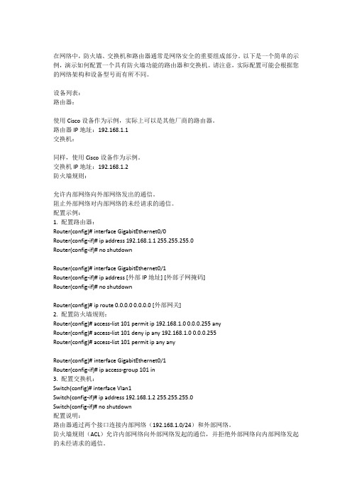
在网络中,防火墙、交换机和路由器通常是网络安全的重要组成部分。
以下是一个简单的示例,演示如何配置一个具有防火墙功能的路由器和交换机。
请注意,实际配置可能会根据您的网络架构和设备型号而有所不同。
设备列表:路由器:使用Cisco设备作为示例,实际上可以是其他厂商的路由器。
路由器IP地址:192.168.1.1交换机:同样,使用Cisco设备作为示例。
交换机IP地址:192.168.1.2防火墙规则:允许内部网络向外部网络发出的通信。
阻止外部网络对内部网络的未经请求的通信。
配置示例:1. 配置路由器:Router(config)# interface GigabitEthernet0/0Router(config-if)# ip address 192.168.1.1 255.255.255.0Router(config-if)# no shutdownRouter(config)# interface GigabitEthernet0/1Router(config-if)# ip address [外部IP地址] [外部子网掩码]Router(config-if)# no shutdownRouter(config)# ip route 0.0.0.0 0.0.0.0 [外部网关]2. 配置防火墙规则:Router(config)# access-list 101 permit ip 192.168.1.0 0.0.0.255 anyRouter(config)# access-list 101 deny ip any 192.168.1.0 0.0.0.255Router(config)# access-list 101 permit ip any anyRouter(config)# interface GigabitEthernet0/1Router(config-if)# ip access-group 101 in3. 配置交换机:Switch(config)# interface Vlan1Switch(config-if)# ip address 192.168.1.2 255.255.255.0Switch(config-if)# no shutdown配置说明:路由器通过两个接口连接内部网络(192.168.1.0/24)和外部网络。
hillstone防火墙配置实例介绍

目录一.基本情况介绍 (2)1.车管所机房情况: (2)2.通璟检测站: (2)3.风顺、安运检测站: (2)4.关于防火墙的配置方式: (3)5.关于配置文件: (3)6.关于授权证书: (4)二.车管所防火墙配置说明 (5)1.第12行: (5)2.第90行,地址薄的设置: (5)3.第316行,接口的设置: (7)4.第371行,虚拟路由的配置: (9)5.第381行,策略的配置: (11)三.通璟检测站防火墙的配置: (13)1.第83行,地址薄的设置: (13)2.第290行,接口的配置: (14)3.第312行,虚拟路由的设置: (15)4.第317行,策略的配置: (16)四.风顺检测站防火墙的配置: (17)1.第86行,地址薄的配置: (17)2.第305行,接口的配置: (18)3.第328行,虚拟路由的配置: (19)4.第335行,策略的设置: (21)五.总结 (22)一.基本情况介绍本文档适用于HillStone SG-6000 M2105(车管所)和HillStone SG-6000 NA V20(检测站),网络连接方式为车管所与检测站防火墙用网线直连、车管所与检测站防火墙在同一公安网IP段内两种。
具体配置如下:1.车管所机房情况:数据服务器、应用/通讯服务器、hillstone防火墙、审核电脑1/2的IP分别10.137.186.78/62/68/36/37,系统管理员给的IP地址格式为:;防火墙配置完毕后,车管所服务器设置的IP格式为:webserviceIP:10.136.46.23。
2.通璟检测站:局域网IP地址为192.168.11.*段,网关192.168.11.1。
因为距离短,有一条一百多米网线直接通到车管所机房。
站点服务器、签证申请岗、查验岗、无线路由、PDA、检测线主控、登录机等都接在交换机上,然后交换机接网线到hillstone防火墙的0/1口,到车管所机房的网线接防火墙0/0口。
网络安全之华为USG防火墙配置实例

网络安全之华为USG防火墙配置实例USG5500系列产品是华为技术有限公司面向大中型企业和下一代数据中心推出的新一代电信级统一安全网关设备。
USG5500系列产品部署于网络出口处,有效阻止Internet 上的黑客入侵、DDoS攻击,阻止内网用户访问非法网站,限制带宽,为内部网络提供一个安全可靠的网络环境。
这里华迪教育以此为例,给同学们讲解防火墙配置实例。
华为USG防火墙配置内容:(1)内部网络通过防火墙访问外部网络(NAT)(2)外部网络能够访问内部服务器的映射网站主要配置命令如下:Step 1: 设置内、外网接口IPinterface GigabitEthernet0/0/1ip address 192.168.10.1 255.255.255.0interface GigabitEthernet0/0/8ip address 211.95.1.200 255.255.255.0Step 2: 指定内网信任区和外网非信任区firewall zone trustdetect ftp (启用FTP应用层转换)add interface GigabitEthernet0/0/1firewall zone untrustadd interface GigabitEthernet0/0/8step 3 : 开启内网FTP服务映射到外网,开通区域间的通信许可firewall interzone trust untrustdetect ftp (开启内网到外网的FTP服务映射)firewall packet-filter default permit allstep 4:定义NAT地址池、配置NAT Server发布内网站点服务nat address-group 1 211.95.1.200 211.95.1.200nat server zone untrust protocol tcp global 211.95.1.200 www inside 192.168.10.254 wwwnat server zone untrust protocol tcp global 211.95.1.200 ftp inside 192.168.10.254 ftpnat server zone trust protocol tcp global 211.95.1.200 www inside 192.168.10.254 wwwnat server zone trust protocol tcp global 211.95.1.200 ftp inside 192.168.10.254 ftpStep 5 :配置nat转换,使得内网可以访问外网nat-policy interzone trust untrust outboundpolicy 1action source-natpolicy source 192.168.10.0 0.0.0.255address-group 1Step 6: 配置源地址转换,强制要求内网用户须通过映射地址访问内部服务器nat-policy zone trustpolicy 1action source-natpolicy source 192.168.10.0 0.0.0.255policy destination 211.95.1.254 0 address-group 1。
配置防火墙混合模式(典型配置案例)
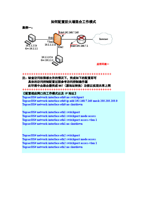
如何配置防火墙混合工作模式案例一:++++++++++++++++++++++++++++++++++++++++注:缺省访问权限都允许的情况下,完成如下的配置即可具体的访问控制配置过程参考访问控制操作篇此环境中由路由器完成NAT(源地址转换)功能以实现共享上网++++++++++++++++++++++++++++++++++++++++〖配置相应网口的工作模式以及IP地址〗TopsecOS# network interface eth0 no switchportTopsecOS# network interface eth0 ip add 192.168.7.165 mask 255.255.255.0 TopsecOS# network interface eth0 no shutdownTopsecOS# network interface eth1 switchportTopsecOS# network interface eth1 switchport mode accessTopsecOS# network interface eth1 switchport access-vlan 1TopsecOS# network interface eth1 no shutdownTopsecOS# network interface eth2 switchportTopsecOS# network interface eth2 switchport mode accessTopsecOS# network interface eth2 switchport access-vlan 1TopsecOS# network interface eth2 no shutdown配置完毕TopsecOS# network interface vlan.1 no shutdown配置完毕〖配置缺省路由〗TopsecOS# network route add dst 0.0.0.0/0 gw 192.168.7.1建议在此不要选择连接端口,让系统自动选择即可〖简单的配置各个网口区域的缺省策略后即可正常通讯〗TopsecOS# define area add name area_eth0 attribute 'eth0 ' access on TopsecOS# define area add name area_eth1 attribute 'eth1 ' access on TopsecOS# define area add name area_eth2 attribute 'eth2 ' access on++++++++++++++++++++++++++++++++++++++++++++++++++++++++++++++++++ ++++++++++++++++++++++++++++++++++++++++++++++++++++++++++++++++++案例二:++++++++++++++++++++++++++++++++++++注:缺省访问权限都允许的情况下,完成如下的配置即可具体的访问控制配置过程参考访问控制操作篇++++++++++++++++++++++++++++++++++++〖配置相应网口的工作模式以及IP地址〗TopsecOS# network interface eth0 no switchportTopsecOS# network interface eth0 ip add 192.168.7.165 mask 255.255.255.0 TopsecOS# network interface eth0 no shutdownTopsecOS# network interface eth1 switchportTopsecOS# network interface eth1 switchport mode TrunkTopsecOS# network interface eth1 switchport trunk encapsulation dot1q TopsecOS# network interface eth1 switchport trunk native-vlan 1 TopsecOS# network interface eth1 switchport access-vlan 10TopsecOS# network interface eth1 switchport trunk allowed-vlan 1-1000 TopsecOS# network interface eth1 no shutdownTopsecOS# network interface eth2 switchportTopsecOS# network interface eth2 switchport mode accessTopsecOS# network interface eth2 switchport trunk encapsulation dot1q TopsecOS# network interface eth2 switchport trunk native-vlan 1 TopsecOS# network interface eth2 switchport access-vlan 30TopsecOS# network interface eth2 switchport trunk allowed-vlan 1-1000 TopsecOS# network interface eth2 no shutdownTopsecOS# network route add dst 0.0.0.0/0 gw 192.168.7.1〖简单的配置各个网口区域的缺省策略后即可正常通讯〗TopsecOS# define area add name area_eth0 attribute 'eth0 ' access on TopsecOS# define area add name area_eth1 attribute 'eth1 ' access on TopsecOS# define area add name area_eth2 attribute 'eth2 ' access on。
H3C_防火墙典型配置案例集(V7)-6W100-H3C_防火墙IPsec典型配置案例(V7)

[Sysname] pki import domain domain1 der ca filename m9000.cer The trusted CA's finger print is:
MD5 fingerprint:7B6F 9F0B F2E8 8336 935A FB5B 7D03 64E7 SHA1 fingerprint:2040 0532 2D90 817A 3E8F 5B47 DEBD 0A0E 5250 EB7D Is the finger print correct?(Y/N):y
i
ቤተ መጻሕፍቲ ባይዱ
1 简介
本文档介绍 M9000 多业务安全网关和 F5000-S 设备建立 IPsec 隧道的方法,其中 IKE 的认证使用 证书方式。
2 配置前提
本文档不严格与具体软、硬件版本对应,如果使用过程中与产品实际情况有差异,请参考相关产品 手册,或以设备实际情况为准。 本文档中的配置均是在实验室环境下进行的配置和验证,配置前设备的所有参数均采用出厂时的缺 省配置。如果您已经对设备进行了配置,为了保证配置效果,请确认现有配置和以下举例中的配置 不冲突。 本文档假设您已了解 IPsec 特性。
1
3.3 使用版本
本举例是在 M9000 Version 7.1.051, Ess 9105 版本上和 F5000-S 的 T3803P02 版本上进行配置和验 证的。
3.4 配置步骤
3.4.1 M9000 的配置
申请证书有在线申请和本地导入两种方式,本配置采用本地导入方式。
(1) 配置接口 Ten-GigabitEthernet5/0/11、Ten-GigabitEthernet5/0/12 的 IP 地址。 # 配置接口 Ten-GigabitEthernet5/0/11 的 IP 地址。
华为防火墙web配置教程华为防火墙典型案例

Firewall_B(分支1)
点到点 1.1.3.1 预共享密钥 Admin@123 IP地址
Firewall_C(分支
点到点 1.1.3.1 预共享密钥 Admin@123 IP地址
Example5:点到多点IPSec隧道(策略模板)
2
1
Step1 配置Firewall_A(
4 配置外网接口参数。
2
1
3
Step6 配置Firewall_B (分支1)
4
允许分支1中的 私网IP地址访问 总部的私网IP地 址。
5
允许总部 IP地址访 1的私网
6 允许总部的公网IP地址访问
7 允许Firewall_B自身访总
Example5:点到多点IPSec隧道(策略模板)
1 2
3
Step7 配置Firewall_B (分
登录Web配置界面
组网图
192.168.0.*GE0/0/0 192.168.0.1/24 网口
1 配置登录PC自动获取IP地址
缺省配置
管理接口
GE0/0/0
IP地址
192.168.0.1/24
用户名/密码 Firewall
admin/Admin@123
2 在浏览器中输入https://接口IP地址:port
向运营商获取。
Example2:通过PPPoE接入互联网
Ste
2 1
4 配置外网接口参数
Example2:通过PPPoE接入互联网
1 2
3
Step2 配置
4 配置内网接口GE1/0/2的 DHCP服务,使其为局域 内的PC分配IP地址
Example2:通过PPPoE接入互联网
华为USG防火墙配置实例脚本-PPPOE

华为USG防火墙配置实例脚本-PPPOEPPPOE分两部分:PPPOE-Server(例如ADSL局端)和PPPoE Client(ADSL拨号上网。
客户端)PPPOE-Server:G0/0接WAN、G0/1接局域网。
客户端通过PPPOE拨号拿IP上网。
公网IP 129.7.66.2/24、网关129.7.66.1,局域网拨到拿1.1.1.2/8-100的IP 典型应用:小区宽带、酒店等。
============================firewall mode routeinterface GigabitEthernet 0/0ip address 129.7.66.2 24ip route-static 0.0.0.0 0.0.0.0 129.7.66.1firewall zone trustadd interface GigabitEthernet 0/1firewall zone untrustadd interface GigabitEthernet 0/0firewall packet-filter default permit all#------------------------------------interface Virtual-Template 1ppp authentication-mode papip address 1.1.1.1 255.0.0.0remote address pool 1firewall zone trustadd interface Virtual-Template 1interface GigabitEthernet 0/1pppoe-server bind Virtual-Template 1#------------------------------------aaalocal-user usg3000 password simple usg3000ip pool 1 1.1.1.2 1.1.1.100#-----------------------------------acl 2001rule 0 permit source 1.1.1.0 0.255.255.255firewall interzone trust untrustnat outbound 2001=============================PPPOE-Client防火墙G0/0上接ADSL MODEM、局域网G0/1用IP192.168.1.1/24做网关。
防火墙双机热备配置案例

双机热备网络卫士防火墙可以实现多种方式下的冗余备份,包括:双机热备模式、负载均衡模式和连接保护模式。
在双机热备模式下(最多支持九台设备),任何时刻都只有一台防火墙(主墙)处于工作状态,承担报文转发任务,一组防火墙处于备份状态并随时接替任务。
当主墙的任何一个接口(不包括心跳口)出现故障时,处于备份状态的防火墙经过协商后,由优先级高的防火墙接替主墙的工作,进行数据转发。
在负载均衡模式下(最多支持九台设备),两台/ 多台防火墙并行工作,都处于正常的数据转发状态。
每台防火墙中设置多个VRRP备份组,两台/多台防火墙中VRID 相同的组之间可以相互备份,以便确保某台设备故障时,其他的设备能够接替其工作。
在连接保护模式下(最多支持九台设备),防火墙之间只同步连接信息,并不同步状态信息。
当两台/多台防火墙均正常工作时,由上下游的设备通过运行VRRP或HSRP 进行冗余备份,以便决定流量由哪台防火墙转发,所有防火墙处于负载分担状态,当其中一台发生故障时,上下游设备经过协商后会将其上的数据流通过其他防火墙转发。
双机热备模式基本需求图 1 双机热备模式的网络拓扑图上图是一个简单的双机热备的主备模式拓扑图,主墙和一台从墙并联工作,两个防火墙的Eth2接口为心跳口,由心跳线连接用来协商状态,同步对象及配置信息。
配置要点设置HA心跳口属性设置除心跳口以外的其余通信接口属于VRID2指定HA的工作模式及心跳口的本地地址和对端地址主从防火墙的配置同步WEBUI配置步骤1配置HA心跳口和其他通讯接口地址HA心跳口必须工作在路由模式下,而且要配置同一网段的IP以保证相互通信。
接口属性必须要勾选“ ha-static选项,否则HA心跳口的IP地址信息会在主从墙运行配置同步时被对方覆盖。
主墙a)配置HA心跳口地址。
① 点击网络管理> 接口,然后选择“物理接口”页签,点击eth2接口后的“设置”图标,配置基本信息,如下图所示。
点击“确定”按钮保存配置② 点击eth2接口后的“设置”图标,在“路由模式”下方配置心跳口的IP地址,然后点击“添加”按钮,如下图所示。
思科ASA5505防火墙配置成功实例
˼¿ÆASA5505·À»ðǽÅäÖóɹ¦ÊµÀý×÷Õߣºjx_wangl¡- ÎÄÕÂÀ´Ô´£º±¾Õ¾Ô-´´ µã»÷Êý£º1357 ¸üÐÂʱ¼ä£º2009-12-14 ÅäÖÃÒªÇó£º1¡¢ ·Ö±ð»®·Öinside£¨ÄÚÍø£©¡¢outside£¨ÍâÍø£©¡¢dmz£¨°²È«Çø£©Èý¸öÇøÓò¡£2¡¢ ÄÚÍø¿É·ÃÎÊÍâÍø¼°dmzÄÚ·þÎñÆ÷£¨web£©£¬ÍâÍø¿É·ÃÎÊdmzÄÚ·þÎñÆ÷£¨web£©¡£3¡¢ Dmz·þÎñÆ÷·Ö±ð¿ª·Å80¡¢21¡¢3389¶Ë¿Ú¡£ËµÃ÷£ºÓÉÓÚ·À»ðǽÐí¿ÉÏÞÖÆ¡°no forward interface Vlan1¡±dmzÄÚ·þÎñÆ÷ÎÞ·¨·ÃÎÊÍâÍø¡£¾ßÌåÅäÖÃÈçÏ£ºÏ£Íû¶ÔÐèÒªµÄÅóÓÑÓÐËù°ïÖúASA Version 7.2(4)!hostname asa5505enable password tDElRpQcbH/qLvnn encryptedpasswd 2KFQnbNIdI.2KYOU encryptednames!interface Vlan1nameif outsidesecurity-level 0ip address ÍâÍøIP ÍâÍøÑÚÂë!interface Vlan2nameif insidesecurity-level 100ip address 192.168.1.1 255.255.255.0 !interface Vlan3no forward interface Vlan1nameif dmzsecurity-level 50ip address 172.16.1.1 255.255.255.0 !interface Ethernet0/0description outside!interface Ethernet0/1description insideswitchport access vlan 2!interface Ethernet0/2description dmzswitchport access vlan 3!interface Ethernet0/3description insideswitchport access vlan 2!interface Ethernet0/4shutdown!interface Ethernet0/5shutdown!interface Ethernet0/6shutdown!interface Ethernet0/7shutdown!ftp mode passiveobject-group service outside-to-dmz tcpport-object eq wwwport-object eq ftpport-object eq 3389access-list aaa extended permit tcp any host ÍâÍøIP object-group outside- to-dmzaccess-list bbb extended permit tcp host 172.16.1.2 192.168.1.0 255.255.255.0 ob ject-group outside-to-dmzpager lines 24mtu outside 1500mtu inside 1500mtu dmz 1500icmp unreachable rate-limit 1 burst-size 1asdm image disk0:/asdm-524.binno asdm history enablearp timeout 14400global (outside) 1 interfaceglobal (dmz) 1 172.16.1.10-172.16.1.254 netmask 255.255.255.0nat (inside) 1 192.168.1.0 255.255.255.0nat (dmz) 1 172.16.1.0 255.255.255.0alias (inside) 221.203.36.86 172.16.1.2 255.255.255.255static (dmz,outside) tcp interface www 172.16.1.2 www netmask 255.255.255.255 d nsstatic (dmz,outside) tcp interface ftp 172.16.1.2 ftp netmask 255.255.255.255 d nsstatic (dmz,outside) tcp interface 3389 172.16.1.2 3389 netmask 255.255.255.255 dnsstatic (inside,dmz) 172.16.1.2 192.168.1.0 netmask 255.255.255.255 dnsaccess-group aaa in interface outsideaccess-group bbb in interface dmzroute outside 0.0.0.0 0.0.0.0 ÍâÍøÍø¹Ø 1timeout xlate 3:00:00timeout conn 1:00:00 half-closed 0:10:00 udp 0:02:00 icmp 0:00:02timeout sunrpc 0:10:00 h323 0:05:00 h225 1:00:00 mgcp 0:05:00 mgcp-pat 0:05:00 timeout sip 0:30:00 sip_media 0:02:00 sip-invite 0:03:00 sip-disconnect 0:02:00 timeout sip-provisional-media 0:02:00 uauth 0:05:00 absoluteno snmp-server locationno snmp-server contactsnmp-server enable traps snmp authentication linkup linkdown coldstarttelnet timeout 5ssh timeout 5console timeout 0!class-map inspection_defaultmatch default-inspection-traffic!!policy-map type inspect dns preset_dns_mapparametersmessage-length maximum 512policy-map global_policyclass inspection_defaultinspect dns preset_dns_mapinspect ftpinspect h323 h225inspect h323 rasinspect netbiosinspect rshinspect rtspinspect skinnyinspect esmtpinspect sqlnetinspect sunrpcinspect tftpinspect sipinspect xdmcpinspect http!service-policy global_policy globalprompt hostname contextCryptochecksum:9d2a6010d4fc078cf026f98dcec96007: endasa5505(config)#。
H3C防火墙二层模式配置案例
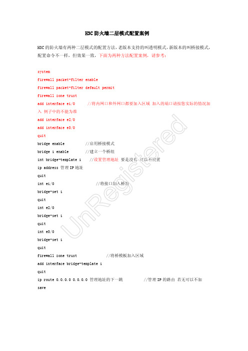
H3C 防火墙二层模式配置案例H3C 的防火墙有两种二层模式的配置方法,老版本支持的叫透明模式,新版本的叫桥接模式,配置命令不一样,但效果一致,下面为两种方法配置案例,请参考:systemfirewall packet-filter enablefirewall packet-filter default permitfirewall zone trustadd interface e1/0 //将内网口和外网口都要加入区域,加入的端口请按您实际的情况加入,例子中的不能为准add interface e2/0add interface e3/0quit bridge enable //启用桥接模式bridge 1 enable //建立一个桥组int bridge-template 1 //设置管理地址,要是没有,可以不设置ip address 管理IP 地址 quitint e1/0 //将接口加入桥组 bridge-set 1quitint e2/0bridge-set 1quitint e3/0bridge-set 1quitfirewall zone trust //将桥模板加入区域add interface bridge-template 1quitip route 0.0.0.0 0.0.0.0 管理地址的下一跳 //管理IP 的路由,若无可以不加 saveU n R e g i s t e r e d透明模式:system-view (进入系统模式)firewall packet-filter enable (开起防火墙功能)firewall packet-filter default permit(配置防火墙默认规则)firewall mode transparent (配置为透明模式)firewall system-ip 192.168.1.254 255.255.255.0 (这是防火墙的管理IP 地址) interface Ethernet2/0(进入WAN 口)promiscuous (配置为透明传输) interface Ethernet1/0 (进入LAN 口)promiscuous (配置为透明传输) firewall zone trust(进入区域) add interface e2/0(把WAN 口加入该区域)add interface e1/0(把LAN 口加入该区域)如果防火墙上行有DHCP 服务器的话,需要配置,系统视图:firewall unknown-mac flood (未知MAC 泛洪) bridge 1 firewall unknown-mac floodU n R e g i s t e r e d。
防火墙典型配置举例

1.1 防火墙典型配置举例1. 组网需求该公司通过一台Quidway路由器的接口Serial 0访问Internet,公司内部对外提供WWW、FTP和Telnet服务,公司内部子网为129.38.1.0,其中,内部FTP服务器地址为129.38.1.1,内部Telnet服务器地址为129.38.1.2,内部WWW服务器地址为129.38.1.3,公司对外地址为202.38.160.1。
在路由器上配置了地址转换,这样内部PC机可以访问Internet,外部PC可以访问内部服务器。
通过配置防火墙,希望实现以下要求:●外部网络只有特定用户可以访问内部服务器●内部网络只有特定主机可以访问外部网络在本例中,假定外部特定用户的IP地址为202.39.2.3。
2. 组网图图1-1防火墙配置的组网图3. 配置步骤# 打开防火墙功能。
[Quidway] firewall enable# 设置防火墙缺省过滤方式为允许包通过。
[Quidway] firewall default permit# 配置访问规则禁止所有包通过。
[Quidway] acl 101[Quidway-acl-101] rule deny ip source any destination any# 配置规则允许特定主机访问外部网,允许内部服务器访问外部网。
[Quidway-acl-101] rule permit ip source 129.38.1.4 0 destination any[Quidway-acl-101] rule permit ip source 129.38.1.1 0 destination any[Quidway-acl-101] rule permit ip source 129.38.1.2 0 destination any[Quidway-acl-101] rule permit ip source 129.38.1.3 0 destination any# 配置规则允许特定用户从外部网访问内部服务器。
CentOS 配置防火墙操作实例

CentOS 配置防火墙操作实例(启、停、开、闭端口):注:防火墙的基本操作命令:查询防火墙状态:[root@localhost ~]# service iptables status<回车>停止防火墙:[root@localhost ~]# service iptables stop <回车>启动防火墙:[root@localhost ~]# service iptables start <回车>重启防火墙:[root@localhost ~]# service iptables restart <回车>永久关闭防火墙:[root@localhost ~]# chkconfig iptables off<回车>永久关闭后启用:[root@localhost ~]# chkconfig iptables on<回车>1、查看防火墙状态[root@localhost ~]# service iptables status<回车>2、编辑/etc/sysconfig/iptables文件。
我们实例中要打开8080端口和9990端口用编辑器打开/etc/sysconfig/iptables3、依葫芦画瓢,我们添加8080端口和9990端口4、保存/etc/sysconfig/iptables文件,并在终端执行[root@localhost ~]# service iptables restart <回车>5、从新查看防火墙状态[root@localhost ~]# service iptables status<回车>6、这时候,服务器的8080和9990端口就可以对外提供服务了。
7、其他端口的开放模式就是类似如此开放模式。
- 1、下载文档前请自行甄别文档内容的完整性,平台不提供额外的编辑、内容补充、找答案等附加服务。
- 2、"仅部分预览"的文档,不可在线预览部分如存在完整性等问题,可反馈申请退款(可完整预览的文档不适用该条件!)。
- 3、如文档侵犯您的权益,请联系客服反馈,我们会尽快为您处理(人工客服工作时间:9:00-18:30)。
C I S C O5520防火墙配置实例本人在项目中已经两次接触到思科5500系列防火墙的配置应用了,根据项目的需求不同,详细的配置也不一样,因此汇总了一个通用版本的思科5500系列防火墙的配置,不详之处,请各位大虾给予指点,谢谢!CD-ASA5520# show run: Saved:ASA Version (2)!hostname CD-ASA5520&nb sp; //给防火墙命名enable password 9jNfZuG3TC5tCVH0 encrypted // 进入特权模式的密码namesdns-guard!interface GigabitEthernet0/0 //内网接口:duplex full //接口作工模式:全双工,半双,自适应nameif inside //为端口命名:内部接口insidesecurity-level 100 //设置安全级别 0~100 值越大越安全!interface GigabitEthernet0/1 //外网接口nameif outside //为外部端口命名:外部接口outsidesecurity-level 0!interface GigabitEthernet0/2nameif dmzsecurity-level 50!interface GigabitEthernet0/3shutdownno nameifno security-levelno ip address!interface Management0/0 //防火墙管理地址shutdownno nameifno security-levelno ip address!passwd encryptedftp mode passiveclock timezone CST 8dns server-group DefaultDNSaccess-list outside_permit extended permit tcp any interface outside eq 3389//访问控制列表access-list outside_permit extended permit tcp any interface outside range 30000 30010//允许外部任何用户可以访问outside 接口的30000-30010的端口。
pager lines 24logging enable //启动日志功能logging asdm informationalmtu inside 1500 内部最大传输单元为1500字节mtu outside 1500mtu dmz 1500//定义一个命名为vpnclient的IP地址池,为remote用户分配IP地址no failovericmp unreachable rate-limit 1 burst-size 1asdm image disk0:/no asdm history enablearp timeout 14400 //arp空闲时间为14400秒global (outside) 1 interface //由于没有配置NAT 故这里是不允许内部用户上INTERNET//端口映射可以解决内部要公布的服务太多,而申请公网IP少问题。
access-group outside_permit in interface outside//把outside_permit控制列表运用在外部接口的入口方向。
timeout conn 1:00:00 half-closed 0:10:00 udp 0:02:00 icmp 0:00:02timeout sunrpc 0:10:00 h323 0:05:00 h225 1:00:00 mgcp 0:05:00 mgcp-pat 0:05:00 timeout sip 0:30:00 sip_media 0:02:00 sip-invite 0:03:00 sip-disconnect 0:02:00 timeout uauth 0:05:00 absolute------------定义一个命名为vpnclient的组策略-------------------------group-policy vpnclient internal //创建一个内部的组策略。
group-policy vpnclient attributes //设置vpnclient组策略的参数vpn-idle-timeout none //终止连接时间设为默认值vpn-session-timeout none //会话超时采用默认值vpn-tunnel-protocol IPSec //定义通道使用协议为IPSEC。
split-tunnel-policy tunnelspecified //定义。
default-domain value //定义默认域名为------------定义一个命名为l2lvpn的组策略------------------------- group-policy l2lvpn internalgroup-policy l2lvpn attributesvpn-simultaneous-logins 3vpn-idle-timeout nonevpn-session-timeout nonevpn-tunnel-protocol IPSecusername test password P4ttSyrm33SV8TYp encrypted privilege 0//创建一个远程访问用户来访问安全应用username cisco password 3USUcOPFUiMCO4Jk encryptedhttp server enable //启动HTTP服务no snmp-server locationno snmp-server contactsnmp-server enable traps snmp authentication linkup linkdown coldstart //snmp的默认配置crypto ipsec transform-set ESP-DES-MD5 esp-des esp-md5-hmac//配置转集(定义了IPSC隧道使用的加密和信息完整性算法集合)crypto dynamic-map vpn_dyn_map 10 set transform-set ESP-DES-MD5//为动态加密图条目定义传换集crypto map outside_map 10 ipsec-isakmp dynamic vpn_dyn_map//创建一个使用动态加密条目的加密图crypto map outside_map interface outside//将 outside_map加密图应用到outside端口------------配置IKE--------------crypto isakmp enable outside //在ostside 接口启动ISAKMPcrypto isakmp policy 20 //isakmmp权值,值越小权值越高authentication pre-share //指定同位体认证方法是共享密钥encryption des //指定加密算法hash md5 //指定使用MD5散列算法group 2 //指定diffie-hellman组2lifetime 86400 //指定SA(协商安全关联)的生存时间crypto isakmp policy 65535authentication pre-shareencryption deshash md5group 2lifetime 86400-------------调用组策略-----------------crypto isakmp nat-traversal 20tunnel-group DefaultL2LGroup general-attributes //配置这个通道组的认证方法default-group-policy l2lvpn //指定默认组策略名称。
tunnel-group DefaultL2LGroup ipsec-attributes //配置认证方法为IPSECpre-shared-key * //提供IKE连接的预共享密钥tunnel-group vpnclient type ipsec-ra //设置连接类型为远程访问。
tunnel-group vpnclient general-attributes //配置这个通道组的认证方法address-pool vpnclient //定义所用的地址池default-group-policy vpnclient //定义默认组策略-----设置认证方式和共享密钥-------------tunnel-group vpnclient ipsec-attributes //配置认证方法为IPSECpre-shared-key * //提供IKE连接的预共享密钥telnet timeout 5 //telnet 超时设置ssh timeout 60 //SSH连接超时设置console timeout 0 //控制台超时设置dhcp-client update dns server both!的地址池dhcpd enable inside //启动DHCP服务。
!!class-map inspection_defaultmatch default-inspection-traffic!!policy-map type inspect dns migrated_dns_map_1 parametersmessage-length maximum 512policy-map global_policyclass inspection_defaultinspect dns migrated_dns_map_1inspect ftpinspect h323 h225inspect h323 rasinspect netbiosinspect rshinspect rtspinspect skinnyinspect esmtpinspect sqlnetinspect sunrpcinspect tftpinspect sipinspect xdmcp!service-policy global_policy globalprompt hostname context: end。
