HL-310R智能绝缘电阻表检定装置
特高压绝缘子检测机器人零值检测方案

特高压绝缘子检测机器人零值检测方案绝缘子运行中因雷击、机械负载和高电压的长期共同作用,会引起劣化。
导致其击穿电压不断下降。
当它下降到小于爬行干闪电压时,就称为低值绝缘子。
内部击穿电压为零时,称为零值绝缘子。
当绝缘子串中有低值或零值绝缘子时,在肮脏的环境中,在过电压甚至工作电压的作用下,容易发生闪络事故。
绝缘电阻合格的标准:(1)500Kv及以上电压等级绝缘子的绝缘电阻应大于或等于500M Ω。
(2)500Kv以下电压等级输电线路绝缘子的绝缘电阻应大于或等于300MΩ。
造成绝缘子劣化的原因有很多,主要有以下几个方面:(1)温度的影响,温度对绝缘电阻影响很大,绝缘电阻随温度上升而减小。
原因是温度升高,绝缘介质的极化加剧,电导增加使绝缘电阻下降,变化的原因与温度变化程度和绝缘材料的性质、结构等有关。
(2)湿度的影响,湿度对表面泄漏电流的影响较大,原因是绝缘表面吸附潮气,形成水膜,会使绝缘电阻明显下降。
(3)绝缘子机械过载造成的劣化。
(4)瓷件吸湿性劣化。
(5)瓷件内外应力重叠性劣化。
(6)瓷绝缘子热膨胀造成的劣化。
(7)钢帽浇装水泥饱和膨胀性劣化。
(8)钢帽浇装水泥冻结膨胀性劣化。
(9)钢帽、钢脚电腐蚀性劣化。
(10)绝缘子过电压造成的劣化。
(11)绝缘子内部缺陷造成的劣化。
绝缘子的检测分为在线检测:观察法、紫外成像法、超声波检测法、以非电量检测为代表的红外测温,以及以绝缘电阻、电场测量、脉冲电流法和漏电流法为代表的典型的电量检测两种。
(1)直接观测法常见的表面缺陷,如护套、伞裙、金具等部位有无开裂,有无电蚀损、粉化、漏电痕迹等,如有以上现象应立即更换绝缘子。
但地面观察不够可靠,还需登塔检测而且难以发现绝缘子内故障,如树枝状通道等。
(2)绝缘子电阻测定法良好绝缘子的绝缘电阻,一般在数千兆欧以上,劣质绝缘子,其表现为绝缘电阻降低、甚至为零。
该方法可停电、也可带电测量,属接触式。
该方法是目前最为直接可靠的检测方法。
绝缘电阻测试仪
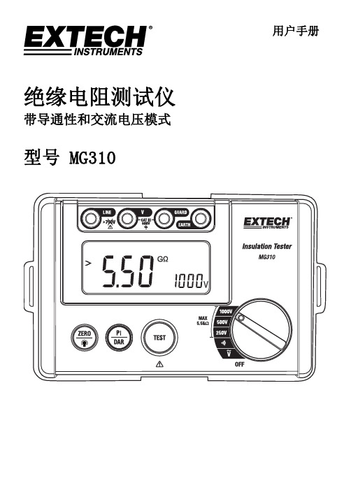
3. SET(设置)按钮:开启/关闭 IR 测试、导通性和交流电压测试。 4. 旋转功能拔盘:选择 IR 输出测试电压(250V/500V/1000V)、测量低电阻(导通性)
或测量交流电压(ACV)。
4
MG310-zh-CN_V1.0 12/15
显示屏说明
1. 电池状态图标
1
2 34 5 6 7
绝缘电阻测试仪
带导通性和交流电压模式
型号 MG310
用户手册
简介
感谢您选购 MG310 型绝缘电阻测试仪。该仪表用来测量绝缘电阻、导通性和交流电压。 MG310 符合 CAT III 600V AC 标准,是测量绝缘材料和变压器、电缆、开关和家用电器等 电气设备的理想之选。可用于包括维护、试验和检查等应用。正确并小心使用此仪表,您 便可常年享受其可靠服务。
5. 背光 LCD 显示屏
6. ZERO(归零)按钮(短按)和 LCD 背光开启/关闭按钮(长按)
7. PI/DAR 测试选择按钮
8. TEST 按钮
9. 旋转功能拨盘
注意:固定位于仪表后部的电池仓。
控制按钮
1. PI/DAR 按钮:按下选择 PI 极化指数和 DAR(电介质吸收比)测试模式。 2. ZERO(归零)/背光按钮:长按开启/关闭 LCD 背光或短按使显示屏归零以测量低电
显示屏背光
按下并按住电源按钮 2 秒钟可以开启或关闭背光。为节约电池电量,请仅在需要时使用背 光。
保持
为了便于使用,自动保持功能 会在短时间内冻结显示屏上的绝缘电阻读数。
低电量指示
当
图标显示在显示屏上时,表示电池电量不足,应予以更换。请参考本用户手册的
电池更换章节。
5
DL T845. 1-2004电阻测量装置通用技术条件 说明书

尊敬的顾客感谢您购买本公司产品。
在您初次使用该仪器前,请您详细地阅读本使用说明书,将可帮助您熟练地使用本仪器。
我们的宗旨是不断地改进和完善公司的产品,因此您所使用的仪器可能与使用说明书有少许的差别。
若有改动,我们不一定能通知到您,敬请谅解!如有疑问,请与公司售后服务部联络,我们定会满足您的要求。
由于输入输出端子、测试柱等均有可能带电压,您在插拔测试线、电源插座时,会产生电火花,小心电击,避免触电危险,注意人身安全!◆慎重保证本公司生产的产品,在发货之日起三个月内,如产品出现缺陷,实行包换。
一年(包括一年)内如产品出现缺陷,实行免费维修。
一年以上如产品出现缺陷,实行有偿终身维修。
◆安全要求请阅读下列安全注意事项,以免人身伤害,并防止本产品或与其相连接的任何其它产品受到损坏。
为了避免可能发生的危险,本产品只可在规定的范围内使用。
只有合格的技术人员才可执行维修。
—防止火灾或人身伤害使用适当的电源线。
只可使用本产品专用、并且符合本产品规格的电源线。
正确地连接和断开。
当测试导线与带电端子连接时,请勿随意连接或断开测试导线。
产品接地。
本产品除通过电源线接地导线接地外,产品外壳的接地柱必须接地。
为了防止电击,接地导体必须与地面相连。
在与本产品输入或输出终端连接前,应确保本产品已正确接地。
注意所有终端的额定值。
为了防止火灾或电击危险,请注意本产品的所有额定值和标记。
在对本产品进行连接之前,请阅读本产品使用说明书,以便进一步了解有关额定值的信息。
请勿在无仪器盖板时操作。
如盖板或面板已卸下,请勿操作本产品。
使用适当的保险丝。
只可使用符合本产品规定类型和额定值的保险丝。
避免接触裸露电路和带电金属。
产品有电时,请勿触摸裸露的接点和部位。
在有可疑的故障时,请勿操作。
如怀疑本产品有损坏,请本公司维修人员进行检查,切勿继续操作。
请勿在潮湿环境下操作。
请勿在易爆环境中操作。
保持产品表面清洁和干燥。
-安全术语警告:警告字句指出可能造成人身伤亡的状况或做法。
共立3125绝缘电阻仪使用说明注意事项

共立3125绝缘电阻仪使用说明一、数字绝缘电阻测试仪使用前注意事项1、电池后盖在没有盖好之前严禁使用,否则有电击危险;2、在使用之前应检查表笔的绝缘层是否完好,有无破损;3、为避免电击,在测试时请勿接触测试线上裸露金属及被测电路;4、测试前请先确认量程选择,功能开关应设定在适当的范围;5、确定测试线的连接插头已紧密的插入端子内;6、请勿在仪表于潮湿状态下使用;7、请勿在测量时转动功能选择开关;8、切勿测量交/直流电压在600V以上的电路。
9、请勿在易燃性场所进行测试,火花可能引起爆炸;10、机壳或表笔接线发生断裂而造成金属外露时,请停止使用;11、打开电池后盖换电池时,请务必确定测试表笔已从测试端子移除,功量程选择开关置于"OFF"位置;12、仪表于潮湿状态下请勿更换电池;13、使用过后请务必将功能量程选择开关置于"OFF"位置;14、长时间不使用时,请将电池取出保管;15、仪表显示“”,无电时,应及时更换电池,以确保测量准确度。
二、数字绝缘电阻测试仪工作参数产品类型:高压绝缘测试仪接口:接线端子液晶显示:液晶显示状态指示灯:有电源:DC12V: 碱性电池(LR14)x 8节尺寸:152*205*94mm重量:2000g工作温度:0℃-40℃工作湿度:相对湿度85% 或更少些三、功能介绍及使用方法1、TRAC-LOK模式1)TRAC模式:按下测试开关后可进行测量,需要连续测量时,使用本模式,如图1所示。
图12)LOK模式:按下测试开关后可测量一次,停止输出后自动放电,此功能可延长电池寿命。
如图2、图3所示。
图2 图3(2)背光功能 背光功能便于在昏暗处使用,易于读取数据。
如图4将功能开关调节至“OFF ”以外的位臵后按下BACK LIGHT 键,背光灯将持续40秒后自动熄灭。
图42、测试前准备工作(1)电池电压测试1)将功能转化开关调至除“OFF ”外的任意位臵均可以进行电压检测,但必须确保被测回路断路。
TH9320交直流耐压绝缘电阻测试仪器说明书
OPERATION MANUAL
MODEL TH9310/20 系列
交直流耐压绝缘电阻测试仪器
Withstanding Voltage/Insulation Resistanctronic Co.,Ltd
地 址 :江 江苏 苏常 常州 州新 新北 北区 区天 天山 山路 路3 3号 号
TH9310/20 系列用户手册 Ver1.1.6
------------------------------
2014.6
TH9310/20 系列仪器使用说明书
Ver1.1.6
目录
第 1 章 开箱安装 ______________________________________________________________ 1 1.1 开箱检查 _____________________________________________________________ 1 1.2 使用注意事项 _________________________________________________________ 2 1.3 移动时的注意要点 _____________________________________________________ 3 1.4 检查电源和保险丝 _____________________________________________________ 3 1.5 连接交流电源线 _______________________________________________________ 4 1.6 接地 _________________________________________________________________ 4 1.7 操作检查 _____________________________________________________________ 5 1.8 仪器的其它特性 _______________________________________________________ 5 第 2 章 操作规范和措施 ________________________________________________________ 6 2.1 禁止的操作行为 _______________________________________________________ 6 2.2 紧急情况的处理 _______________________________________________________ 6 2.3 测试中的预防措施 _____________________________________________________ 6 2.4 高压测试警告 _________________________________________________________ 7 2.5 有故障仪器的危险状态处理 _____________________________________________ 8 2.6 保证长时间无故障使用的条件 ___________________________________________ 8 2.7 日常检查 _____________________________________________________________ 8 第 3 章 仪器面板概述 __________________________________________________________ 9 3.1 前面板说明 ___________________________________________________________ 9 3.2 后面板说明 __________________________________________________________ 11 3.3 多通道模块说明 ______________________________________________________ 12 3.4 仪器性能概述 ________________________________________________________ 13 第 4 章 基本操作 _____________________________________________________________ 17 4.1 仪器界面结构概述 ____________________________________________________ 17 4.2 面板功能界面和参数说明 ______________________________________________ 18 4.2.1 SETUP 测量设置 _______________________________________________ 20 4.2.2 TEST 测试界面 ________________________________________________ 21 4.2.3 SYSTEM 系统界面 ______________________________________________ 22 4.2.4 FILE 文件存储界面。___________________________________________ 24 4.3 测试项目界面和参数说明 ______________________________________________ 26 4.3.1 AC 交流耐压测试参数设定 ______________________________________ 26 4.3.2 DC 直流耐压测试参数设定 ______________________________________ 27 4.3.3 IR 绝缘电阻测试参数设定 _______________________________________ 28 4.3.4 OS 开短路检测测试参数设定 ____________________________________ 29 4.3.5 MF 多路辅助控制设定 __________________________________________ 30 4.4 测试功能原理与使用说明 ______________________________________________ 31 4.4.1 启动测试 _____________________________________________________ 31 4.4.2 测试时延 _____________________________________________________ 31 4.4.3 电压上升 _____________________________________________________ 32
Model 310 数字毫厘拾法电阻计说明书

Instruction Manual Model 310 Digital Milli-Ohm MeterDESCRIPTION PAGE SAFETY RULES (01)GENERAL DESCRIPTION.................................... 02-03 FRONT PANEL LAYOUT (04)PREPARATION FOR USE (05)PRELIMINARY CHECKS (05)PRECAUTIONS (06)MEASURING (07)SIMPLIFIED MEASUREMENT (08)APPLICATIONS (09)TEST LEADS (10)THERMAL EFFECTS (11)FUSES REPLACEMENT (11)INPUT LIMITS & PROTECTIONS (12)SPECIFICATIONS (13)SPARES & ACCESSORIES (14)LIMITED ONE-YEAR WARRANTY........................ 14-15 CLEANING & STORAGE.. (16)BATTERY & FUSE REPLACEMENT (16)SERVICE INFORMATION (17)SAFETY RULESThe meter has been designed with safety in mind. However, no design can completely protect against incorrect use. Electrical circuits are dangerous and lethal through lack of caution or poor safety practice. The following rules should reduce the danger:• Read the User's manual carefully and completely before using the instrument. Fully understand the instructions before using this product. Follow the instructions for every test. Take all the necessary precautions. Do not exceed the limits of this instrument.• The circuit to be tested must be de-energized and isolated before connections are made to it.• Do not use test leads, probes or crocodiles/alligatorsclips that are dirty, damaged or have broken or cracked insulation. Such accessories should be removed and repaired Immediately.• Always disconnect the test leads before replacing any fuse Always replace the fuse with the type specified and ensure that they are correctly fitted.• Double check the switch settings and leads connections before measuring. Make a sketch to ensure proper operation and principle of measurement is correct and well understood.• Do not touch any exposed wiring, connections or other "live" parts of an electrical circuit. If in doubt, check the circuit first for voltage before touching it.• This instrument should only be used by a competent, suitably trained person which understand fully this test & measurement procedure.Warning, risk of electric shock.GENERAL DESCRIPTIONThe meter digital milli-ohmmeter is a battery operated instrument which supply a low current to the circuit under test, with which, stable, accurate measurement of low resistance can be made, still, over a wide range of values.Resolution on the lowest range is 100µΩ and on the highest range, 1Ω.The meter has 5 measuring ranges, from 200.0mΩ to 2000Ω. Measurements are displayed on a 3½ digit custom liquid crystal display with large digits.This instrument is powered from batteries only.It has a regulated DC constant current source with current of1mA 10mA and 100mA.The instrument supply that current to the resistance being measured through the C1 and C2 terminals (C1 being +, C2 being -). The voltage drop across the resistance under test is measured by the potential terminals P1 and P2 (P1 being +, P2 being -). Should the current regulation drop out, the R C LED will lit, indicating that the resistance in the current circuit is too high. (Lowering the current by selecting a higher resistance range can solve the regulation.)Should the R P LED lit, that mean that the voltage measured on the resistance is too high, and therefore over-range.The resistance is measured precisely when the R P and R C LEDs do not lit. If anyone of these LEDs lit, then the measurement can be inaccurate.can be viewed in most lightning conditions. This display indicates the differences conditions (Hold, m, buzzer, polarity condition of load, + or -, automatic decimal point change).The ranges are selected by a 5 position rotary switch, and a test is initiated by pressing the ON push-button.The instrument takes measurements for 10 seconds if the "ON" "TEST r e" presentative" button is depressed for less than 2 seconds. If the same push button is pressed for more than 3 seconds, the test will carry on for 60 seconds.The tester switch "OFF" completely when the rotary switch is in the "OFF" position.The tester "Hold" the last reading before stopping the test.The tester is fuse protected and has a crowbar between C1 and C2.This crowbar is activated by voltage. If the voltage is too high, that crowbar will blow the fuse automatically to interrupt the circuit.The voltage between P1 and P2 is also protected for over voltage but does not have a fuse.The tester has a temperature shut down. The temperature sensing is done on the current regulation transistor.Should this over-temperature let lit, allow the instrument to cool down for a while before proceeding further.FRONT PANEL LAYOUTIf NO TEST LED lit, the current source is stopped.Over Temperature indicator. Lit = Over-temperature or Array test stopped.Resistance between the current leads too high (fuse!).Resistance between the potential leads too high.Meet LVD & EMCRotary Selector Switch requirementsPREPARATION FOR USEWhen unpacked, the tester should be inspected for any visible signs of damage, and the preliminary checks described in the user's manual should be performed to ensure that it is operating correctly. If there is any sign of damage, or if the instrument does not operate correctly, return it to your nearest supplier. PRELIMINARY CHECKSCheck the battery• If the battery symbol is shown on the LCD, then replace with new batteries before proceeding.Check the current regulation:• Connect the current leads to C1 and C2.• Select a range, and short the current test leads. The R C LED should go off, indicating that the current regulation is ok. Check the voltage measurement:• Connect the potential leads to P1 and P2.• Short the P1 and P2. The display should indicate 0000.• Remove the short from P1 and P2 and C1 and C2. Touching the potential test leads P1 to C1 and P2 to C2, the R P LED should lit, indicating an over-voltage or over-range.This proving test can be repeated on all the ranges if need be. You can also check the polarity indication of the milli-voltmeter by touching the potential test leads P1 to C2 and P2 to C1, the R P LED should lit, indicating an over-voltage or over-range. The - indicator should be indicating - on the LCD, showing the polarity change.Total check can be done by shorting all the test leads together C1, C2, P1, P2. The display should indicate close to 0000 (depending of the crocodiles clips used and how they are shorted). Both R C and R P LED should be OFF, indicating thatPRECAUTIONS• Always ensure that the circuit to be measured is switched "OFF", isolated and completely de-energized before connecting the test Leads.• If it is probable that the instrument's protection has been impaired due to electrical, mechanical or environmental damage, it must not be used. It should be returned to your nearest distributor or agent for checking and repair.• To prevent damage to the liquid crystal display, the minimum storage temperature of -20°C must be observed. It should also be noted that below 0°C the operation of the LCD will be sluggish.• If the exterior of the instrument requires cleaning, it should be done with a sponge and a mild solution of detergent and water.• Other mechanical cleaning agents must not be used.MEASURING• Perform the preliminary checks before proceeding with measurement and ensure that the precautions listed are observed.• Connect the test leads (color coded) to the instrument as shown.• The current test leads must always be outside of the potential test leads.• Please note that the shorter the potential test leads, the better long potential test leads will pick up noise.• Screened test leads are recommended for better environmental noise rejection.SIMPLIFIED MEASUREMENTThe 4 wires measurement has many advantages. The errors due to the resistance of the test leads and the contacts aswell as R A and R B are eliminated. However, in some cases, for example when using the high resistance range (2000Ω) the four wires method is not necessary to still have a good percentage of accuracy (compared to the full scale). The simplified method of two wires can be used without too much problems. C1 and P1 can be shorted as well as C2 and P2.APPLICATIONSThe meter Digital milli-ohmmeter, with its measuring range of 100µΩ to 2000Ω, is suitable for a wide range of applications such as:• Measuring the winding resistance of electric motors, generators and transformers.• Bond testing in mines, aircraft, railways, ships, domestic and industrial wiring installations.• Measuring the ring main continuity testing in industrial and domestic wiring installations.• Measuring resistance in electronic equipment such as shunts, pcb tracks, switch and relay resistance.• Checking compression joints on overheads lines.• Testing and maintenance of switchboard /sub-station equipment on such items as fuses, joints, contacts and bonds.TEST LEADSThe test leads supplied with the instrument are suitable forconnecting to conductors up to 17mm in diameter or bus bars17mm tick. There will be, instances where the item beingmeasured require larger jaws, and the user is advised to makeup his own leads. There will be occasions when longer leadsare required due to the geometry of the item being tested. Someguidance notes should assist in the assembly of such leads: Length of the potential leads should be as short as possible. Insulated 16/0.2mm, tinned copper wire is recommended. The two potential leads should have the samelength to minimize inaccuracies due to unbalance. SUPPLIED POTENTIAL TEST LEADSP1+ test lead is of Red color, shrouded, 4mm safety plug whichat one end have a crocodile (alligator) clip for connection to theresistance to be measured. The other end plugs into the meter(4mm shrouded) color coded sockets.P2- test lead is of Blue color, shrouded, 4mm safety plug whichat one end have a crocodile (alligator) clip for connection to theresistance to be measured. The other end plugs into the meter(4mm shrouded) color coded sockets.SUPPLIED CURRENT TEST LEADSC1+ test lead is of Green color, shrouded, 4mm safety plugwhich at one end have a crocodile (alligator) clip for connectionto the resistance to be measured. The other end plugs into themeter (4mm shrouded) color coded sockets.C2- test lead is of Black color, shrouded, 4mm safety plug whichat one end have a crocodile (alligator) clip for connection to theresistance to be measured. The other end plugs into the meterTHERMAL EFFECTSTemperature can have a significant effect on the performance of a digital milli-ohmmeter due to the temperature coefficient of the resistance under test and thermal EMF's across the dissimilar conductors.Most conductors have a large temperature coefficient of resistance.For example: 0.4%/°C for copper. A copper conductor that has a resistance of 10.00mΩ at 20°C will increase to 10.40mΩ at 30°C. This change should be taken into account when making measurements.A current going through a resistance will also elevate its temperature. So duration of the test can change the resistance. When measuring the resistance of item, such as current shunts, which have joints of dissimilar conductors, thermal EMF can affect the accuracy of the measurement. This condition canbe detected if the reading alters when the leads are reversed. To compensate for this effect, the average of the two readings should be taken as the true measurement.FUSES REPLACEMENTThere are three fuses:• Power Supply FuseThe power supply fuse is situated under the tester. Open the battery compartment and replace the fuse with the same type (0.5A / 250Vac, 5 x 20mm)• Current Circuit FuseFuse protection is provided on the current terminals.This fuse is situated under the Printed Circuit Board. To access it, you need to unscrew the four mounting screwslocated under the foots, and the two others are located inside the battery compartment.The fuse is automatically blow by the crowbar, should voltage be present on the resistance under test. This is to prevent damage to the instrument.It is indicative of this fuse being blown is the R C LED stays "on". (0.5A / 250Vac, 5 x 20mm)• Potential Circuit FuseFuse protection is provided on the potential terminals.This fuse is situated under the Printed Circuit Board. To access it, you need to unscrew the four mounting screws which are holding the font panel. Two of these screws are located under the foots, and the two others are located inside the battery compartment.The fuse is automatically blow by the crowbar, should voltage be present on the resistance under test. This is to prevent damage to the instrument.If the preliminary tests does not lit R P this is indicative of this fuse being blown. (0.5A / 250Vac, 5 x 20mm)INPUT LIMITS & PROTECTIONSThe maximum continuous voltage which can be applied across the potential and current leads is around 10.7V. Applying more than that voltage will automatically blow their respective fuses. However, the crowbar trigger can be factory adjusted for your application.We have specially selected that method to stop damaging the instrument, should it be misused.SPECIFICATIONSMeasuring Ranges0-200.0mΩ in steps of 100µΩ0-2000mΩ in steps of 1mΩ0-20.00Ω in steps of 10mΩ0-200.0Ω in steps of 100mΩ0-2000Ω in steps of 1ΩAccuracy±0.5% of reading ±2 digits over theOperating temperature range, -15°Cto +55°C, with the supplied test leads. Test Current1mA : 2000Ω range10mA : 200Ω / 20Ω ranges100mA : 2000mΩ / 200mΩ ranges Test Current Accuracy ±0.1%Protection Fuses Supply = 0.5A, 5 x 20mmCurrent = 0.5A, 5 x 20mmVoltage = 0.5A, 5 x 20mmSafety LVD EN 61010-1EMC EN 61326-1 MECHANICALCase Height: 110mmCase Width: 250mmCase Depth: 190mmDrop Test: EN 61010, Clause 8.3Weight: 1.563kgRated environmental conditions(1) Indoor Use(2) Pollution Degree 2(3) Altitude up to 2000 meter(4) Relative humidity 80% max.(5) Ambient temperature 0°C~40°CSPARES & ACCESSORIESAt the date of printing this user's manual, accessories were not yet available. Please contact the factory for further information. Spares are available from your nearest distributor.LIMITED ONE-YEAR WARRANTYB&K Precision warrants to the original purchaser that its products and the component parts thereof, will be free from defects in workmanship and materials for a period of oneyear from date of purchase from an authorized B&K Precision distributor.B&K Precision will, without charge, repair or replace, at its option, defective product or component parts. Returned product must be accompanied by proof of the purchase date in the form of a sales receipt.To obtain warranty coverage in the U.S.A., this product must be registered by completing the warranty registration form on www. within fifteen (15) days of purchase. Exclusions: This warranty does not apply in the event ofmisuse or abuse of the product or as a resultof unauthorized alterations or repairs. Thewarranty is void if the serial number is altered,defaced or removed.B&K Precision shall not be liable for any consequential damages, including without limitation damages resulting from loss of use. Some states do not allow limitations of incidental or consequential damages. So the above limitation or exclusion may not apply to you.This warranty gives you specific rights and you may have other rights, which vary from state-to-state.B&K Precision22820 Savi Ranch ParkwayYorba Linda, CA 92887714-921-9095CLEANING & STORAGEPeriodically wipe the case with a damp cloth and detergent: do not use abrasives or solvents.If the meter is not to be used for periods of longer than 60 days, remove the batteries and store them separately. BATTERY & FUSE REPLACEMENTBattery Replacement• The tester continuously monitors the battery voltage and indicates when the batteries need to be replaced.• The tester's battery is situated under the tester.• Disconnect the test leads from the instrument and remove the battery cover and the batteries.• Replace with eight 1.5V AA batteries, taking care to observe correct polarity.• Replace battery holder and the battery cover.Fuse Replacement• The fuse is located under the battery holder.• To replace fuse, open the battery cover. Then remove and replace the fuse located under the battery holder.• Only replace with same fuse specification. (500mA)CAT IV - Is for measurements performed at the source of the low voltage installation.CAT III - Is for measurements performed in the buildingInstallationCAT II - Is for measurements performed on circuits directly connected to the low-voltage installation.Due to our policy of constant improvement and development, we reserve the right to change specifications without notice.SERVICE INFORMATIONWarranty Service:Please return the product in the original packaging with proofof purchase to the address below. Clearly state in writing the performance problem and return any leads, probes, connectors and accessories that you are using with the device.Non-Warranty Service:Return the product in the original packaging to the address below. Clearly state in writing the performance problem and return any leads, probes, connectors and accessories that you are using with the device. Customers not on open account must include payment in the form of a money order or credit card. For the most current repair charges please visit www.bkprecision. com and click on "service/repair".Return all merchandise to B&K Precision with pre-paid shipping. The flat-rate repair charge for Non-Warranty Service does not include return shipping. Return shipping to locations in North American is included for Warranty Service only. For overnight shipments and non-North American shipping fees please contact B&K Precision.B&K Precision22820 Savi Ranch ParkwayYorba Linda, CA 92887714-921-9095Include with the returned instrument your complete return shipping address, contact name, phone number and description of problem.B&K Precision22820 Savi Ranch ParkwayYorba Linda, CA 92887U.S.A.Printed in Taiwan / Ver. 1.1/0920© 2020 B&K Precision Corporation。
绝缘电阻测试仪检定标准(JJG62-97)
绝缘电阻表(兆欧表)检定规程VerificationRegulationofMegohmmeterJJG622—97本检定规程经国家技术监督局于1997年10月24日批准,并自1998年5月1日起施行。
归口单位:国家高电压计量站起草单位:国家高电压计量站本规程技术条文由起草单位负责解释。
本规程主要起草人:黄盛洁(国家高电压计量站)黄卫民(国家高电压计量站)参加起草人:谭德荣(国家高电压计量站)绝缘电阻表(兆欧表)检定规程本规程仅适用于测量绝缘电阻的直接作用模拟指示的绝缘电阻表(包括新制造的、使用中的及修理后的绝缘电阻表)的检定,不适用于数字式及特殊用途,而其技术要求与本规程规定不同的测量绝缘电阻用的仪表。
一概述1规格1.1绝缘电阻表按额定电压分为9种:50,100,250,500,1000,2000,2500,5000,10000V 。
1.2绝缘电阻表按准确度等级分为5级:1.0,2.0,5.0,10.0,20.0。
1.3绝缘电阻表检定环境的参考温度为23℃。
1.4绝缘电阻表的原理图见附录1。
它的主要组成部分是直流电源装置的指示仪表。
1.4.1直流电源装置可分为:a.内附手摇发电机;b.化学电源(如干电池);c.交流电网和整流电路配合的装置。
1.4.2指示仪表分为:磁电系电流表及磁电系比率表。
二技术要求2基本误差2.1绝缘电阻表的基本误差按公式(1)进行计算。
在标度尺测量范围(有效范围)内,每条选定分度线的基本误差极限值应不超过表1的规定。
(1)式中B p ——绝缘电阻表指示器标称值;B R ——标准高压高阻箱示值;A F ——基准值。
2.2对非线性标尺的绝缘电阻表的基准值规定为测量指示值。
PR F100%B B E A ⎛⎫-=⨯ ⎪⎝⎭2.3对非线性标尺的绝缘电阻表的量程划分为三个区段(Ⅰ,Ⅱ,Ⅲ),如图1所示。
图1绝缘电阻表量程区段2.4Ⅱ区段长度由厂家提出,但不得小于标尺全长的50%。
共立电气计器株式会社 3125 数字式高压绝缘电阻测试仪 使用说明书

使用说明书日本共立电气计器株式会社目录1.安全警告---------------------------------------------1 2.特点-------------------------------------------------4 3.技术规格---------------------------------------------5 4.仪器布局图4-1仪器布局图----------------------------------------8 4-2液晶屏显示----------------------------------------9 5.测试前的准备5-1检查电池电压--------------------------------------10 5-2连接测试导线--------------------------------------10 6.测试6-1电压测量(600V或更少些)---------------------------11 6-2绝缘电阻的测量------------------------------------12 6-3连续测量------------------------------------------15 6-4定时器测量功能------------------------------------15 6-5极化指数测量--------------------------------------15 6-6测量接线端的电压特性------------------------------15 6-7保护接线的使用----------------------------------15 7.电池更换---------------------------------------------191.安全警告本仪器的设计、制造和检测均达到IEC61010安全标准(电子类测量产品安全要求),本手册包括确保仪器的安全使用及保证仪器的安全状态,使用者所必须遵守的警告和安全条例。
三相智能电能表检定装置招标文件

三相智能电能表检定装置招标文件一、招标项目概况1、项目名称:三相智能电能表检定装置采购项目2、项目编号:_____3、招标单位:_____4、招标内容:三相智能电能表检定装置若干套二、投标人资格要求1、投标人须为在中华人民共和国境内注册的独立法人,具有有效的营业执照。
2、投标人应具有良好的商业信誉和健全的财务会计制度,提供近三年(_____年_____年)的财务审计报告或财务报表。
3、投标人须具有履行合同所必需的设备和专业技术能力,提供相关证明材料或书面声明。
4、投标人在近三年内(_____年_____年),在经营活动中没有重大违法记录,提供书面声明。
5、本项目不接受联合体投标。
三、招标文件的获取1、凡有意参加投标者,请于_____年_____月_____日至_____年_____月_____日(法定公休日、法定节假日除外),每日上午_____时至_____时,下午_____时至_____时(北京时间,下同),在_____(详细地址)持单位介绍信购买招标文件。
2、招标文件每套售价_____元,售后不退。
四、投标文件的递交1、投标文件递交的截止时间(投标截止时间,下同)为_____年_____月_____日_____时_____分,地点为_____(详细地址)。
2、逾期送达的或者未送达指定地点的投标文件,招标人不予受理。
五、开标时间及地点1、开标时间:_____年_____月_____日_____时_____分2、开标地点:_____(详细地址)六、设备技术要求1、装置应能满足国家相关标准和规程对三相智能电能表的检定要求,包括但不限于准确度、功能、通信等方面的检测。
2、测量范围:电压应能覆盖 3×(577 380)V,电流应能覆盖 3×(01 100)A。
3、准确度等级:装置的整体准确度等级应不低于 005 级。
4、具备对电能表的基本误差、启动试验、潜动试验、时钟误差、费率和时段功能、需量功能、通信功能等项目的检定能力。
计量检定收费标准

±0。2μm
(0~2000)mm
台
2100
C-003—003
标准玻璃线纹尺
二等
(0~100)mm
支
540
二等
(0~200)mm
支
700
标准金属线纹尺(含光栅尺)
二等
(0~1000)mm
支
1050
三等
(0~1000)mm
支
450
C-004—004
基线尺(只检长度)
±20μm
台
200
C—072—072
磁阻法测厚仪
A级,B级,C级
(0~10)mm
台
200
C-073-073
光滑量规
(0~200)mm
只
35
C—074-074
半径样板
片
10
C-075-075
螺纹环规
只
100
C-076-076
螺纹塞规
支
100
C—077—077
塞尺
片
10
C-078-078
电感式比较仪
台
350
C-079-079
(150×150)mm
台
300
小型工具显微镜
±3μm
(75×50)mm
台
300
C—016-016
光切显微镜
台
220
干涉显微镜
台
300
测量显微镜
±(5μm+L/15)
(0~25)mm
台
150
C—017-017
水平仪检定器
5%
2mm/m
台
200
水平仪
绝缘电阻测试仪内校证书模板
1、计量合格证书号:M—0 2 3 6
2、校准所依据的技术文件:L H / C·1 2·1 1
3、本中心出具的数据均可溯源至国家计量基准
4、校准所使用的计量标准:
仪器名称
型号
编号
准确度
制造厂商
兆欧表检定装置
ZCA-301
0228
0.2级
北京远东仪东有限公司
5、校准的环境条件:
温度:23℃,相对温度:60 %
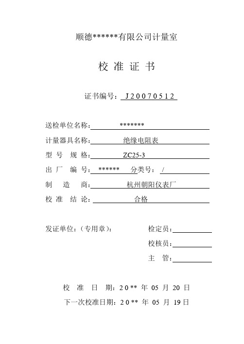
顺德******有限公司计量室
校准证书
证书编号:J 2 0 0 7051 2
送检单位名称:*******
计量器具名称:绝缘电阻表
型号规格:ZC25-3
出厂编号:******分类号:/
制造商:杭州朝阳仪表厂
校准结论:合格
发证单位:(专用章):检定员:
校核员:
主管:
校准日期:2 0**年05月20日
下一次校准日期:2 0**年05月19日
校准记录
序号
检测项目
显示值
实际值
1
外观Βιβλιοθήκη 符合要求2绝缘电阻
(MΩ)
1.0
5.0
10.0
50.0
100.0
200.0
500.0
1.002
5.008
10.022
50.062
100.136
200.245
500.532
校准结论:合格
智能双显绝缘电阻测试仪技术参数

智能双显绝缘电阻测试仪技术参数智能双显绝缘电阻测试仪采用嵌入式工业单片机实时操作系统,超薄形张丝表头与图形点阵液晶显示器完美结合,系列表具有多种电压输出等级(500V、1000V、2500V、5000V)、容量大、抗干扰强、指针与数字同步显示、交直流两用、操作简单、自动计算各种绝缘指标吸收比、极化指数、各种测量结果具有防掉电功能等特点。
是测量大容量变压器、互感器、发电机、高压电动机、电力电容、电力电缆、避雷器等绝缘电阻的理想测试仪。
产品别名:双显绝缘电阻测试仪、高压绝缘电阻测试仪、绝缘电阻测试仪、数字式兆欧表、电子兆欧表、绝缘表、兆欧表智能双显绝缘电阻测试仪技术参数:特性:(1)有多种电压输出选择BC2000(2500V/5000V)、BC2010(500V、1000V、2500V、5000V),测量电阻量程范围可达0~200GΩ,电阻量程范围可自动转换,并有相应的指示。
(2)两种方式同步显示绝缘阻值。
机械指针采用超薄型张丝结构抗震能力强。
机械指针的采用可容易观察绝缘电阻的变化范围,点阵液晶屏的采用可指导用户操作仪表并可精确得出测量结果。
(3)机械表头与液晶屏合二为一。
双刻度显示,量程自动转换。
彩色刻度易于读识,并有LED显示相应色彩。
(4)采用嵌入式工业单片机和实时操作软件系统。
自动化程度高、抗干扰能力强,仪器可自动计算吸收比和极化指数,无须人工干预。
(5)操作界面友好,各种测量结果具有防掉电功能,可连续存储20次的测量结果。
(6)仪表产生高压时,有提示音输出。
(7)内置残留高压放电电路,测试完毕可自动放掉被测设备上的残留高压。
(8)交直流两用,配置可充电池和交流适配器。
(9)仪表采用便携式设计,便于野外操作。
(10)高压短路电流≥3mA,是测量大型变压器、互感器、发电机、高压电动机、电力电容、电力电缆、避雷器等绝缘电阻的理想测试仪器。
尊敬的客户:感谢您关注我们的产品,本公司除了有此产品介绍以外,还有变频串联谐振,串联谐振试验装置,变频串联谐振耐压试验装置,变压器油耐压测试仪,高压绝缘垫、短路接地线、继电保护测试仪、高压核相仪等等的介绍,您如果对我们的产品有兴趣,咨询。
- 1、下载文档前请自行甄别文档内容的完整性,平台不提供额外的编辑、内容补充、找答案等附加服务。
- 2、"仅部分预览"的文档,不可在线预览部分如存在完整性等问题,可反馈申请退款(可完整预览的文档不适用该条件!)。
- 3、如文档侵犯您的权益,请联系客服反馈,我们会尽快为您处理(人工客服工作时间:9:00-18:30)。
南京鸿陆电气有限公司
www .njhldq .com
智能绝缘电阻表检定装置型号:HL -310R
●概述
●主要特点
● HL-310R 依据JJG622-1997《绝缘电阻表检定规程》、JJG1005-2005《电子式绝缘电阻表检定规程》等相关国家标准、 电力行业标准研制而成。
● HL-310R 是一款精密、灵活的仪器,用户可以高效率地校准各种类型的绝缘电阻测试仪。
HL-310R 以单台仪器的形式取 代了分立的电阻器、电阻箱和其它自制的校准解决方法。
● HL-310R 代替传统的多台仪器可以让您在校准绝缘电阻测试仪时节省宝贵的工作台空间,并简化校准过程,更加安全, 更加方便。
● HL-310R 非常容易使用。
宽大、明亮的全彩色7寸显示屏显示清晰,并能够以易于理解的图形化方式显示正在测试时需要 连接的端钮。
仪器内置的帮助附带插图,还可为您提供所需的其他帮助。
■ 程控电阻源输出;
■ 可输出大电阻、高压电阻,并测量兆欧表或其他便携式和台式绝缘测试仪的高压输出;■ 7寸彩色液晶屏显示,电阻值、端钮电压、稳定度、峰值、中值电压等参数一目了然。
■ 具备各种保护功能,量限程控切换,使用安全可靠;
■ 步进可根据需要通过旋转编码器调节,高压高值电阻最小步进值为100Ω;
● 应用
数字式绝缘电阻表(兆欧表、摇表)
指针式绝缘电阻表(兆欧表、摇表)大电阻测试仪......
Nanjing Honglu Technologys Co.,Ltd
●技术指标
01/02高压高值电阻源
直流表
范围: 100Ω-100GΩ
步进值: 100Ω
(程控连续可调)
最大电压范围: 10K V
最优技术指标:
100Ω-10MΩ 设置值的 ±0.2%
10MΩ-100MΩ 设置值的 ±0.5%
100MΩ-1GΩ 设置值的 ±1%
1GΩ-10GΩ 设置值的 ±2%
10GΩ-100GΩ 设置值的 ±5%
电压范围: 0-10K V
电压分辨率: 0.01V
最优一年技术指标: 读数的±0.5%。