旋启式止回阀安装、操作维护手册
止回阀使用说明书
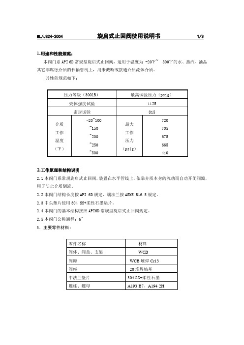
ML/JS24-2004 旋启式止回阀使用说明书 1/31.用途和性能规范:本阀门系API 6D常规型旋启式止回阀,适用于温度为 -20℉~ 800℉的水、蒸汽、油品其它非腐蚀介质的长输管线上,用来截断或接通介质流体介质。
其性能规范如下:2.工作原理和结构说明2.1本阀门系常规旋启式止回阀,装置在水平管线上,依靠介质本身的流动而自动开闭阀瓣,用于防止介质倒流。
2.2本阀门结构长度按API 6D规定,端法兰按ASME B16.5规定。
2.3中头垫片使用304 SS+柔性石墨垫片。
2.4本阀门的基本结构按照API6D常规型旋启式止回阀规定。
2.5本阀门公称通径:6"3.主要零件材料:ML/JS24-2004 旋启式止回阀使用说明书 2/3 4 阀门的流量系数验算:4保管、保养、按装调试、使用及维修4.1保管保养4.1.1本阀门应存放在干燥、通风的室内,阀门两端应封堵。
4.1.2存放的阀门应定期检查,清除污垢,并在加工面上涂防锈油。
4.1.3按装后,应定期进行检修。
4.1.4检修装配后,应进封试验,并作详细记录,以备查考。
4.2按装调试4.2.1按装前,仔细检查本阀门标志是否与使用要求相符。
4.2.2按装前,应检查阀门内腔和密封面,不允许有污垢附着。
4.2.3阀门按装或拆卸其所需空间应予考虑。
4.2.4在阀门按装于配管时,为防止阀瓣受配管的铁锈或其它物质的损坏,阀门应处于全开为位置。
4.2.5阀门在长期存放后,在使用前应进行操作试验。
4.2.6阀门按装后,应检查联接螺栓是否均匀拧紧。
4.3使用4.3.1在使用中,要求阀瓣将全开或全闭,不允许将闸板部分开启作调节流量用,否则在介质较高流速时,易损坏密封面。
4.3.2开启或关闭阀门时,应用手轮,不得借助杠杆或其它工具。
4.4维修ML/JS24-2004 旋启式止回阀使用说明书 3/3。
旋启式止回阀AWWA C508-2009

10.特殊涂层和衬里(见 4.4.12)。
11.特殊标记(见6.1.2)。
12.合规宣誓书(见6.3)。
前言重点内容
3.2.修改标准。在本标准中任何条款、定义或术语的修改,必须
由买方提供。
4.重大修改。该版本(2009版)标准的重大修改包括以下内容:
1.压力等级的修订。 见1.1.4。
2.阀门长度尺寸从附录中添加到该标准内容中。 见4.4.2和表2。
4.当地以及其他联邦,州或省的详细需求(见4.3)。
5.制造商需要的数据(见4.2秒)。
前言重点内容
6.止回阀的管道系统是具有电化学腐蚀的水质,因此禁止使用 含有超过16%锌的青铜材料(Sec 4.3.2.2.3)。 7.除ASTM A307 (4.3.2.3)中指定以外的其他螺栓材料的机 械和化学性能 8.阀门端面的连接类型-----法兰连接或机械接合以及阀体长度 (见10/24/11)。 9.阀门的详细描述。如果尺寸或其他特定的加工(见 4.4.7)。
旋启式止回阀
旋启式止回阀的关闭件是一个与管道通径相当的阀瓣或圆盘,悬挂 于阀门腔体内,流体正向流动时在流体压力的作用下阀瓣打开,压力下 降时阀瓣在自重和逆流流体的压力作用下关闭。 旋启式止回阀由阀体、阀盖、阀瓣和摇杆组成。阀瓣呈圆盘状,绕阀 座通道外的销轴做旋转运动。阀内通道呈流线型,流动阻力比直通式升 降止回阀要小,适合用于大口径的管道。但低压时,其密封性能不如升 降式止回阀。为提高密封性能可采用辅助弹簧或采用重锤结构辅助密封 。
标准的主要内容
9买方:要执行的个人,公司或组织购买的任何资料或工作。 10.结构性缺陷:导致阀门组件不符合标准的结构设计和测试要求 的缺陷。这包括,导致在通过铸造时壁泄漏缺陷,未能满足最小壁 厚的要,或无法满足生产测试。
阀门的安装、维护与操作手册
阀门的安装、维护与操作手册阀门的安装、维护与操作正确地选择了阀门之后,还要正确安装、维护与操作,这样才能充分发挥其效能。
第一节安装阀门安装的质量、直接影响着使用,所以必须认真注意。
(一)方向和位置许多阀门具有方向性,例如截止阀,节流阀,减压阀、止回阀等,如果装倒装反,就会影响使用效果与寿命(如节流阀),或者根本不起作用(如减压阀),甚至造成危险(如止回阀)。
一般阀门,在阀体上有方向标志;万一没有,应根据阀门的工作原理,正确识别。
截止阀的阀腔左右不对称,流体要让其由下而上通过阀口,这样流体阻力小(由形状所决定),开启省力(因介质压力向上),关闭后介质不压填料,便于检修。
这就是截止阀为什么不可安反的道理。
其它阀门也有各自的特性。
阀门安装的位置,必须方便于操作;即使安装暂时困难些,也要为操作人员的长期工作着想。
最好阀门手轮与胸口取齐(一般离操作地坪1.2米),这样,开闭阀门比较省劲。
落地阀门手轮要朝上,不要倾斜,以免操作别扭。
靠墙机靠设备的阀门,也要留出操作人员站立余地。
要避免仰天操作,尤其是酸碱、有毒介质等,否则很不安全。
闸阀不要倒装(即手轮向下),否则会使介质长期留存在阀盖空间,容易腐蚀阀杆,而且为某些工艺要求所禁忌。
同时更换填料极不方便。
明杆闸阀,不要安装在地下,否则由于潮湿而腐蚀外露的阀杆。
升降式止回阀,安装时要保证其阀瓣垂直,以便升降灵活。
旋启式止回阀,安装时要保证其销轴水平,以便旋启灵活。
减压阀要直立安装在水平管道上,各个方向都不要倾斜。
(二)施工作业安装施工必须小心,切忌撞击脆性材料制作的阀门。
安装前,应将阀门作一检查,核对规格型号,鉴定有无损坏,尤其对于阀杆。
还要转动几下,看是否歪斜,因为运输过程中,最易撞歪阀杆。
还要清除阀内的杂物。
阀门起吊时,绳子不要系在手轮或阀杆上,以免损坏这些部件,应该系在法兰上。
对于阀门所连接的管路,一定要清扫干净。
可用压缩空气吹去氧化铁屑、泥砂、焊渣和其他杂物。
铸钢旋启式止回阀使用说明书

铸钢旋启式止回阀使用说明书一、用途及结构特点1.用途:VCT止回阀用于工业管道中作为阻止介质逆流装置。
通过选取不同的材质,可用于水、蒸气、油品、硝酸等多种介质。
2.结构特点:VCT铸钢旋启式止回阀采用螺栓连接阀瓣,单瓣旋启式结构,是国际通用的结构。
3.阀座:对于不同压力和规格阀座有以下几种形式:a:采用阀座圈与阀体用螺纹连接或焊接,其中螺纹连接便于维护和更换阀座。
b:在阀体上直接堆焊密封面材料。
c:对不锈钢阀门,其阀座密封面一般在阀体上直接加工成型。
4.中法兰垫片:采用金属缠绕式石墨填充带内环的平面,凹凸或垫片或八角环垫,确保了中道的密封。
二、设计制造标准与规范表2-1 设计制造标准1.以上所标注材料均按ASTM标准,国标材料按照等效国家标准牌号。
2.密封面材料编号为VCT公司编号,内容如下:H:13Cr/13Cr T: 13Cr/HF K: HF/ 13CrY: HF/ HF A:304/304 B :316/316D: 304/ HF E:316/ HF M: HF/304N: HF/316[阀座密封面、阀瓣密封面]三、保管1.该阀门应存放于干燥通风的室内。
2.存放期间启闭件应处于开启位置,通道应用封盖盖紧,并做好防锈措施。
3.长期放置应定期对密封面等部位进行检查,去除污垢灰尘,并涂抹新的防锈油。
四、安装1.止回阀在运往安装现场的过程中,应将阀瓣开启并完全固定,方可进行运送。
2.安装时应注意,必须保证介质的流向与阀体上箭头方向一致。
3.本阀应水平安装在管道上,阀体不能承受管道重量,对大口径的阀门,应加必要的支撑。
4.在安装前必须仔细核对铭牌上的参数,必须能符合管路的工况要求。
五、使用1.使用过程中严禁敲击阀门。
2.使用过程中要随时注意介质的清洁度,同时注意管路介质的粘度不宜过大。
3.使用过程中有轻微的“水锤”现象属正常。
六、检查1.使用过程中应定期对阀门进行检查,发现故障及时排除。
2.常见故障及消除方法见表6-1.表6-1 常见故障及消除方法七、注意事项1.阀门材料的选择及其在使用中变质的可能性和必要的定期检查由用户考虑。
中鼎旋启式法兰连接止回阀安全操作及保养规程
中鼎旋启式法兰连接止回阀安全操作及保养规程中鼎旋启式法兰连接止回阀是一种广泛用于管道系统中的阀门。
为了确保阀门的正常运行和使用寿命的延长,本文将介绍该阀门的安全操作和保养规程。
安全操作操作前准备在操作旋启式法兰连接止回阀之前,需要做好以下准备工作:1.确定操作人员已经了解阀门的使用方法以及相关安全注意事项。
2.确认阀门的位置,并切断与该阀门相邻管道的电源或介质。
3.确保操作人员佩戴个人防护装备,如手套、保护眼镜、头盔等。
操作步骤1.拉开法兰连接的螺丝并卸下法兰,将法兰和密封圈等零件放置在干燥清洁的地方。
2.拆下止回阀正体,检查阀门是否有损坏或泄漏。
3.将止回阀正体重新安装在法兰上。
4.插入法兰螺丝,并逐个紧固,交替顺序紧固至规定扭矩值。
5.启动管道系统并检查阀门的正常运行情况及密封性能。
注意事项操作旋启式法兰连接止回阀时需要注意以下事项:1.在安装阀门时,必须按照生产厂家的安装说明进行操作。
2.在操作该阀门之前,必须确保阀门的管道系统上没有压力。
3.在拆卸法兰连接过程中,需要注意松开螺丝的顺序以及法兰连接处的密封圈情况。
4.在拆卸止回阀正体时,需要立即封堵管道,以免管道内的介质泄漏。
保养规程定期检查对旋启式法兰连接止回阀进行定期检查可以有效延长阀门的使用寿命。
建议进行的检查工作包括:1.检查阀门的密封性能,确保其符合规范要求。
2.检查阀门的防腐蚀情况,防止腐蚀引起的管道故障。
3.检查阀门的操作是否灵活顺畅,不出现卡阻和卡咬等问题。
4.定期更换密封圈等易损件,确保其性能不受损坏降低。
清洁保养对旋启式法兰连接止回阀进行清洁保养可以保证其正常运行和组成部分的完好。
建议进行的保养工作包括:1.定期清洗阀门外表面,避免环境污染的影响。
2.定期检查和清除阀门内外的异物或杂质,防止影响阀门的正常运作。
3.定期对阀门内部进行润滑,确保操作灵活并减少磨损。
结论以上为中鼎旋启式法兰连接止回阀的安全操作及保养规程。
正确操作和定期保养旋启式法兰连接止回阀可以有效地延长阀门的使用寿命和避免由于管道故障引起的不必要损失。
止回阀安装操作手册

止回阀安装操作手册前言止回阀的设计和制造是按照使用寿命长、无故障应用的要求进行并提供给客户的。
本手册给客户提供所有相关阀门安装、操作和长期使用维护的信息,所提供的图纸均为标准结构的图纸。
一、安装前的注意事项1.阀门到达现场后,应仔细检查是否在运输途中受损。
2.在没有完成安装前,应保留阀门的包装和保护的设施。
3.如果阀门的通道以及法兰端面等与管路安装有关的地方被裸露,应采取措施加以保护,以防止杂质进入阀门体腔。
4.阀门安装前,应检查和清洗管道,防止杂质如砂子、电焊渣等损坏阀瓣和阀体密封面。
5.如果阀门在安装使用前需要存放较长时间,应在阀门裸露表面涂上防锈油,并建议将阀门处于全关位置时存放在干燥和通风的地方,通道两端应上好闷盖保护。
长时间存放后安装使用该阀门,应先进行清洗,并重新试压,合格后投入安装使用。
二、安装过程中的操作规程1.阀门不应负载管道的重量。
对管道的支撑将因管道系统的震动造成阀门的变形,阀门可以通过在阀体上安装管道夹和支撑物进行支撑,不应在法兰上固定支撑物(如图9)。
2.不要通过法兰螺栓的调整来纠正管道的不平行。
3.不允许用阀门承载管道的重量来避免管线的扭曲和阻塞。
4.合格的管道焊工必须按照ASME锅炉和压力容器标准第Ⅸ卷的规定进行焊接操作和评定。
5.止回阀安装时,首先要确定管道介质的流向与阀门允许的流向一致;安装螺纹端、对焊端、承插焊端、对夹式及法兰端连接阀门时,必须按照下列不同的程序和方法进行安装,以使阀门达到最佳的性能。
5.1螺纹端阀门的安装5.1.1安装前,应清洗阀门两端螺纹及其附件;5.1.2如必要,密封剂只能使用于管道或外螺纹上;5.1.3应使用带有正确尺寸的平板钳夹的扳手来安装六角或八角端;5.1.4不能选择较小尺寸的螺纹来安装管线阀门。
5.2对焊端阀门的安装5.2.1连接部位应保持同轴,连接端保留2~3mm间隙;5.2.2焊接处应使用内焊接垫环;5.2.3完成焊接后,应冲洗或清刮管道和阀门,以清除焊渣;5.2.4不允许快焊导致焊接材料过剩;5.2.5焊接时应采取适当的措施以避免阀座区域温度过高,使阀座及其密封面损坏;5.2.6如对焊端阀门购买时没有带延长的焊接接头,在焊接前,应拆除中间已经装配好阀瓣和阀座的阀体,并在原位置上安装上相同尺寸的隔离物后进行焊接;5.2.7当管道系统冷却至环境温度时将隔离物拆下,并重新安装阀体。
H44H旋启式止回阀说明书
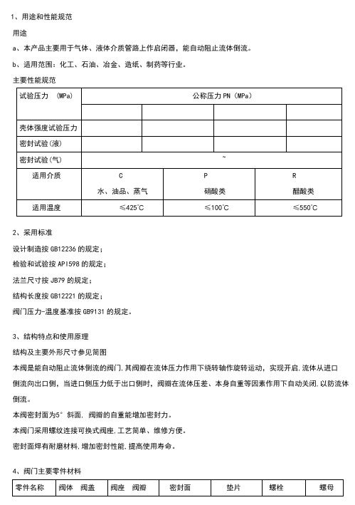
1、用途和性能规范用途a、本产品主要用于气体、液体介质管路上作启闭器,能自动阻止流体倒流。
b、适用范围:化工、石油、冶金、造纸、制药等行业。
主要性能规范2、采用标准设计制造按GB12236的规定;检验和试验按API598的规定;法兰尺寸按JB79的规定;结构长度按GB12221的规定;阀门压力-温度基准按GB9131的规定。
3、结构特点和使用原理结构及主要外形尺寸参见简图本阀是能自动阻止流体倒流的阀门,其阀瓣在流体压力作用下绕转轴作旋转运动,实现开启,流体从进口侧流向出口侧,当进口侧压力低于出口侧时,阀瓣在流体压差、本身自重等因素作用下自动关闭,以防流体倒流。
本阀密封面为5°斜面, 阀瓣的自重能增加密封力。
本阀门采用螺纹连接可换式阀座,工艺简单、维修方便。
密封面焊有耐磨材料,增加密封性能,提高使用寿命。
4、阀门主要零件材料5、保管、安装、使用、检查保管a.本阀须保管存放在干燥、通风的室内。
b.本阀保管存放期闸,阀瓣应处于关闭位置并固定,两端法兰应封闭。
c.本阀存放期间,机加工表面应用容易清除的防锈剂涂覆。
d.长期存放的阀门应定期检查,及时防护。
安装a.本阀安装位置不受限制,通常安装于水平管路,也可以安装于垂直管路或倾斜管路,但要便于检修。
b.安装前,必须仔细核对阀门标志和铭牌是否与工况要求相符。
c.安装时应检查内腔,除去阀瓣固定装置,试转阀瓣检查密封面,并清洗。
d.起吊本阀前,应检查吊环螺钉是否己拧紧。
e.安装本阀时,要特别注意介质流向,应使介质正常流动方向与阀体上箭头指示方向一致,否则会截断介质的正常流向。
f.安装时,应均匀对称拧紧连接螺栓。
使用a.本阀的使用工况必须与铭牌和使用说明书的规定相符。
b.本阀关闭时,会在管路中产生水锤压力,严重时会导致阀门损坏,因此使用者必须定期检查,发现问题及时修理。
检查1.阀门在使用期间应定期检查如下项目发现问题及时修理。
a.紧固件是否出现松动。
b.密封面是否被损坏或严重磨损(停车检修)。
HH44R-10缓冲型旋启式止回阀说明书
HC44R-10型旋启式缓闭防振耐蚀止回阀 使用说明书铁岭市求精阀门厂2013年2月1用途、特点及主要性能规范1.1 主要用途本系列止回阀用于在介质为水、油等液体的管道上,安装在泵出口位置,用来防止介质的逆流和破坏性的水锤。
1.2 特点:1.阀瓣轻、开启角度大、减少流阻,降低能耗。
2.配有调节阻尼油缸为水锤消除机构、设计新颖、结构合理、性能可靠。
3.运动平稳、无震动、无噪音、安全可靠。
4.耐磨损、使用寿命长。
5.适用介质有清水、污水、海水及油品等。
1.2性能规范:型 号 HC44R-10公称压力 1.0MPa适用介质 水、循环水试 验 压 力壳 体 1.5MPa密 封 1.1MPa工作压力P8 1.0MPa介质温度 (℃) ≤80℃其密封渗漏量符合GB/T 13927-2008标准A级(无渗漏)的规定。
2. 主要结构、外形及连接尺寸2.1.结构说明:本止回阀系法兰连接。
2.2本止回阀具体结构及外形尺寸详见图1、表1。
图1.HC44R-10型缓闭防振耐蚀止回阀主要结构、外形及连接尺寸图1.阀体2.阀盖3.阀体密封圈4. 阀杆5. 摇杆6.阀瓣7.阀瓣密封圈8.缓冲装置9.重锤杆 10.重锤表1 DN PN D D1 D2 b f L H B n-d 备 注 700 10 895 840 794 40 5 1448820158024-∅313工作原理:3.1阀门工作原理:当管路内介质正向流动时,借助进口压力作用,使阀瓣旋转开启,介质通过。
同时油缸内油经单向阀导通,阀瓣通过阀杆和摇杆带动平衡锤旋转,到达开启位置。
油缸内液压油产生的阻尼作用可以避免阀瓣开启过快与阀体产生撞击。
当水泵停泵,介质停止流动或逆流时,阀瓣依靠自重、重锤的辅助及逆流的作用,使阀瓣向关阀方向回落,但由于缓冲油缸内单向阀截止,腔内液压油只能通过节流口回油,因此阀瓣的回落速度取决于节流口的流速,调节节流口的过流面积,即可控制止回阀关闭的时间。
旋启式止回阀安装使用与维护

旋启式止回阀安装使用与维护
旋启式止回阀安装使用与维护保养要注意以下方面:
一、安装与使用:
1 -止回阀垂直安装在水平管道上,使用是一般处于全开状态。
2 -安装前应先进行以下工作:
A、卸掉阀门通道两端的闷盖和泡沫板,清洁内腔,去除油垢;
B、剥去阀瓣表面上的油纸,去除阀瓣面上的油垢;
3- 安装时介质的流向必须限制。
4- 通过管路的介质不应带有硬质颗粒,以免损伤密封面
5- 该阀门出厂前应逐台进行检验和试验合格,安装单位可直接压力试验或安装使用。
二、维护与保养:
1-该阀门应存放在干燥通风的室内,做到防潮、防雨、防锈。
2- 存放和运输时启闭件应处于关闭装置,同时应做好以下工作:
(1)阀瓣应固定于开启位置
(2)通径两端内口用泡沫板堵塞,端口须用闷盖塞紧,予以防尘、防锈,保持通道清洁和端面的平整;
(3)密封部位进行适当的包装防护、防震和防碰;
3- 长久放置时应定期检查。
每三个月对两通道、密封面上的污垢和锈迹,焊接口的防护状况进行检查,擦拭污垢和锈迹后,重新涂刷防锈油予以防护。
4、整体结构、简单紧凑、造型美观
5、使用寿命长、可靠性高
6、阀瓣通配,当管道中的止回阀阀瓣受损时,直接将阀盖打开,然后取下销轴,更换一个厂家提供的阀瓣,挂上去即开,方便易行。
【免费下载】 旋启式止回阀产品使用说明书

≤425℃ 水、蒸汽、油品等
材料 304 420
ASTM A193 B7 30CrMo
材料 304+柔性石墨
420 ASTM A193 B7
30CrMo
单位 MPa
6 保管、使用和安装
使用说明书
6.1 本阀门通道两端须堵密封盖,存放有干燥通风的室内。长期存放,应经常检查,防止锈蚀 6.2 安装前,应将阀门清洗干净,并消除在运输过程中可能造成的缺陷。 6.3 安装前,必须仔细核对阀门上的标志和铭牌是否符合使用要求。 6.4 本阀门应安装在水平或垂直管道上的直立或侧卧位置,并便于检修和操作。 6.5 本阀门在运行时应全开或全闭,不能作节流用,以免密封面受冲刷而加速磨损。
≤425℃ 水、蒸汽、油品等
单位 MPa
表2
密封试验
型
压 力等级
壳体试验压力
适用温度
适用介质
液压
号
4 主要外形尺寸和连接尺寸见图一和图二。
5 主要零件的材料
8”H44H-900Lb 的主要零件材料见表 3 表3
零件名称
阀体、阀盖
阀座
阀瓣
摇杆、摇杆支架
10”H44H-600Lb 的主要零件材料见表 4 表4
因
消除方法
1 均匀地拧紧螺母 2 修理密封面,清除污物 3 更换垫片
1 打开阀体,清洗干净
2 重新研磨或重新加工
使用说明书
图一 8”H44H-900Lb 样图
对全部高中资料试卷电气设备,在安装过程中以及安装结束后进行高中资料试卷调整试验;通电检查所有设备高中资料电试力卷保相护互装作置用调与试相技互术关,系电,力根通保据过护生管高产线中工敷资艺设料高技试中术卷资,配料不置试仅技卷可术要以是求解指,决机对吊组电顶在气层进设配行备置继进不电行规保空范护载高与中带资负料荷试下卷高问总中题体资,配料而置试且时卷可,调保需控障要试各在验类最;管大对路限设习度备题内进到来行位确调。保整在机使管组其路高在敷中正设资常过料工程试况中卷下,安与要全过加,度强并工看且作护尽下关可都于能可管地以路缩正高小常中故工资障作料高;试中对卷资于连料继接试电管卷保口破护处坏进理范行高围整中,核资或对料者定试对值卷某,弯些审扁异核度常与固高校定中对盒资图位料纸置试,.卷保编工护写况层复进防杂行腐设自跨备动接与处地装理线置,弯高尤曲中其半资要径料避标试免高卷错等调误,试高要方中求案资技,料术编试交写5、卷底重电保。要气护管设设装线备备置敷4高、调动设中电试作技资气高,术料课中并3中试、件资且包卷管中料拒含试路调试绝线验敷试卷动槽方设技作、案技术,管以术来架及避等系免多统不项启必方动要式方高,案中为;资解对料决整试高套卷中启突语动然文过停电程机气中。课高因件中此中资,管料电壁试力薄卷高、电中接气资口设料不备试严进卷等行保问调护题试装,工置合作调理并试利且技用进术管行,线过要敷关求设运电技行力术高保。中护线资装缆料置敷试做设卷到原技准则术确:指灵在导活分。。线对对盒于于处调差,试动当过保不程护同中装电高置压中高回资中路料资交试料叉卷试时技卷,术调应问试采题技用,术金作是属为指隔调发板试电进人机行员一隔,变开需压处要器理在组;事在同前发一掌生线握内槽图部内 纸故,资障强料时电、,回设需路备要须制进同造行时厂外切家部断出电习具源题高高电中中源资资,料料线试试缆卷卷敷试切设验除完报从毕告而,与采要相用进关高行技中检术资查资料和料试检,卷测并主处且要理了保。解护现装场置设。备高中资料试卷布置情况与有关高中资料试卷电气系统接线等情况,然后根据规范与规程规定,制定设备调试高中资料试卷方案。
阀门操作、维护和使用手册说明(阀门投标专用)
阀门储存、操作、维护和使用说明概述阀门是用来关闭和开启管道中介质。
切断阀没有节流的功能。
该类阀门顺时针旋转手轮,直到完全将通道切断,阀门关闭。
逆时针旋转手轮,直到碰到阻挡,阀门打开。
对于电动装置阀门,在断电等紧急情况下,可以使用备用手轮打开和关闭阀门。
注意!截止阀在不超过10%开启状态连续节流会对阀瓣和阀座引起剧烈振动、噪音、磨损和损坏。
止回阀作为控制管道介质单向流动的元件,当介质顺流时由管线自身压力的作用开启阀门,当介质倒流时依靠阀瓣自身重量、弹簧力和介质回流的压力作用在阀瓣背部,使阀瓣与阀座形成密封,达到止回截流的目的。
警告!禁止用夹泵的方式对阀门进行泵验。
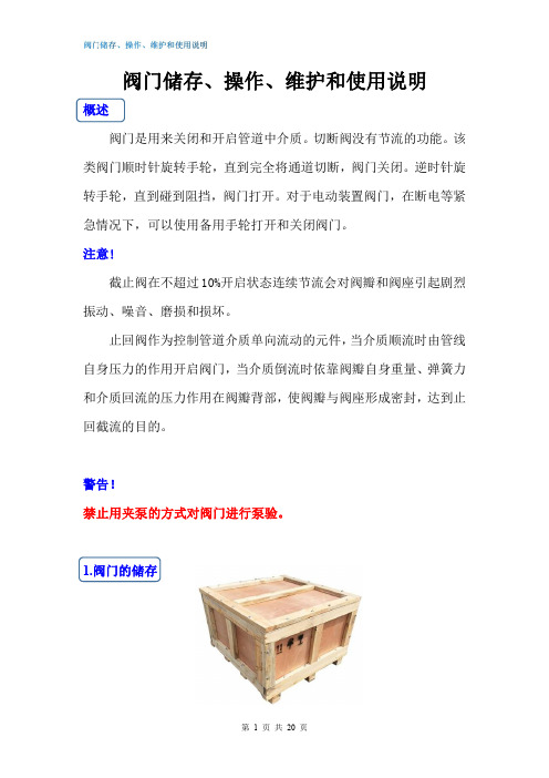
1.阀门的储存1.1发运准备阀门的包装应能防止阀门在运输过程和储存时不发生任何损坏。
并应注意以下几点:①闸阀:包装时,闸板应处于关闭状态。
②截止阀:包装时,阀瓣应处于关闭状态。
②止回阀:包装时,升降式止回阀、蝶形止回阀和对夹立式止回阀应将阀瓣有利于关闭状态摆放;旋启式止回阀和斜瓣式止回阀的阀瓣用丁字形木条顶住,丁字形木条一端撑紧在出口端孔内,以使阀瓣在运输过程中不会碰撞。
对于外接附件如阻尼缸、气缸等,应将附件可靠小心地完全固定。
1.11阀门法兰密封面/焊接坡口/螺纹端应涂合适的防护油脂(不锈钢材质除外),阀门两端应可靠地固接木质、木纤维或塑料端以防护连接端面和阀门内部。
对于闸阀和截止阀:齿轮箱或电动装置阀门包装时须小心地安全固定,以确保齿轮箱或电动装置不会损坏并不至于穿破木箱/板条箱。
1.12包装型式应在订单中明确规定,以便安全地运输至目的地和确保安装前的保存。
1.2吊运要求1.21包装完好的阀门板条箱:用叉车进行装卸。
木箱:在木箱的重心位置处设置装吊点进行装卸。
1.22已开箱的阀门①这些阀门的吊运要采取合适的手段和措施如应用货盘进行装卸,注意应避免加工面受到损坏。
②对大尺寸阀门,在吊运阀门时可用皮带或链条绕过阀体的颈部吊起,并应保持平衡以防止意外坠落或在吊运过程中松动。
对夹单瓣旋启式止回阀选型 - 介绍 - 工作原理 - 安装方式 - 说明
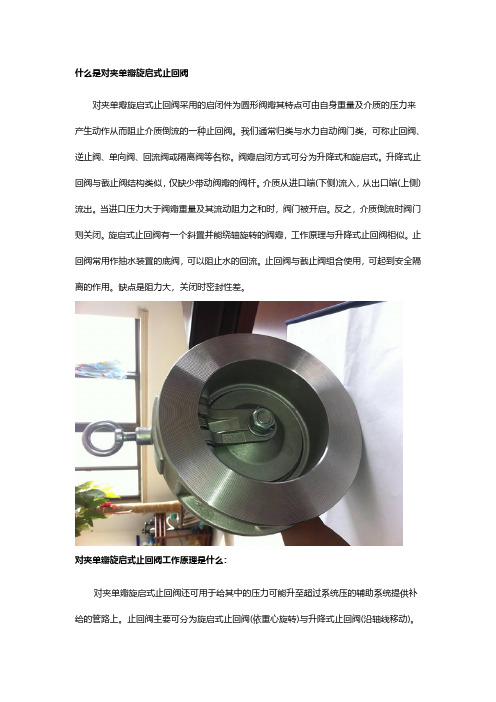
什么是对夹单瓣旋启式止回阀对夹单瓣旋启式止回阀采用的启闭件为圆形阀瓣其特点可由自身重量及介质的压力来产生动作从而阻止介质倒流的一种止回阀。
我们通常归类与水力自动阀门类,可称止回阀、逆止阀、单向阀、回流阀或隔离阀等名称。
阀瓣启闭方式可分为升降式和旋启式。
升降式止回阀与截止阀结构类似,仅缺少带动阀瓣的阀杆。
介质从进口端(下侧)流入,从出口端(上侧)流出。
当进口压力大于阀瓣重量及其流动阻力之和时,阀门被开启。
反之,介质倒流时阀门则关闭。
旋启式止回阀有一个斜置并能绕轴旋转的阀瓣,工作原理与升降式止回阀相似。
止回阀常用作抽水装置的底阀,可以阻止水的回流。
止回阀与截止阀组合使用,可起到安全隔离的作用。
缺点是阻力大,关闭时密封性差。
对夹单瓣旋启式止回阀工作原理是什么:对夹单瓣旋启式止回阀还可用于给其中的压力可能升至超过系统压的辅助系统提供补给的管路上。
止回阀主要可分为旋启式止回阀(依重心旋转)与升降式止回阀(沿轴线移动)。
止回阀这种类型的阀门的作用是只允许介质向一个方向流动,而且阻止反方向流动。
通常这种阀门是自动工作的,在一个方向流动的流体压力作用下,阀瓣打开;流体反方向流动时,由流体压力和阀瓣的自重合阀瓣作用于阀座,从而切断流动。
其中止回阀就属于这种类型的阀门,它包括旋启式止回阀和升降式止回阀。
旋启式止回阀有一介铰链机构,还有一个像门一样的阀瓣自由地靠在倾斜的阀座表面上。
为了确保阀瓣每次都能到达阀座面的合适位置,阀瓣设计在铰链机构,以便阀瓣具有足够有旋启空间,并使阀瓣真正的、全面的与阀座接触。
阀瓣可以全部用金属制成,也可以在金属上镶嵌皮革、橡胶、或者采用合成覆盖面,这取决于使用性能的要求。
旋启式止回阀在完全打开的状况下,流体压力几乎不受阻碍,因此通过阀门的压力降相对较小。
升降式止回阀的阀瓣坐落位于阀体上阀座密封面上。
此阀门除了阀瓣可以自由地升降之外,其余部分如同截止阀一样,流体压力使阀瓣从阀座密封面上抬起,介质回流导致阀瓣回落到阀座上,并切断流动。
阀板旋转型止回阀操作与维护说明-510型 带有层状密封说明书

阀板旋转型止回阀操作与维护说明510型带有层状密封Tiltin g Disc Type Check Valves目录1. 介绍 (2)2. 使用目的 (2)3.安全说明 (2)3.1.安全说明概述 (2)3.2.操作者的安全说明 (2)3.3.特殊危险 (3)4.阀板旋转型止回阀的铭牌 (4)5.运输和存储 (4)6.管道中的安装 (5)6.1.概述 (5)6.2.安装准备 (5)6.3. 安装位置和流向 (6)6.4.安装步骤 (6)7. 压力测试和试车 (7)8. 正规操作和维护 (7)9. 故障诊断指南 (8)10.图纸 (9)10.1.零件明细表 (9)10.2.细部图>阀板旋转型止回阀<带法兰 (10)10.3. 细部图>阀板旋转型止回阀<带焊接头 (11)11.维修说明 (12)11.1.概述 (12)11.2. 更换轴承盖垫圈 (12)11.3.更换轴密封 (12)11.4 更换层密封 (13)Tiltin g Disc Type Check Valves1. 介绍这个手册的目的是帮助用户安装、操作和维修阀板旋转型止回阀。
危险!如果不遵从下面的注意事项和警告,会导致危险。
制造商对此不负有责任。
出现任何问题请联系克隆巴赫。
2. 使用目的在阀板旋转型止回阀被安装到管道系统(通过法兰或焊接连接)和电机(如果是定购的)被连接到控制系统后,止回阀让介质沿流向方向通过,防止回流。
阀板旋转型止回阀原则上是自动阀。
油压闸阻尼关闭或者关闭和打开(根据用户的需求)。
附加的执行机构被安装为了专用功能(与定购有关),例如自动关闭,自动打开等。
⇒ 允许通过的介质包含的固体物质不能多于说允许的的一个非常小的比例。
⇒ 不推荐在带有腐蚀作用的介质中使用阀板旋转型止回阀。
⇒ 最大可允许压力和最大可允许温度表示在阀门的型牌上。
⇒ 如果介质有堆积内部沉淀物的趋势,阀板旋转型止回阀不应该被使用。
旋启式止回阀的正确安装方法

旋启式止回阀的正确安装方法介绍旋启式止回阀是一种常用于管道系统中的阀门,用于防止流体在管道中逆流。
它具有结构简单、操作方便以及密封性好的特点,广泛应用于工业、建筑、给排水等领域。
本文将详细讨论旋启式止回阀的正确安装方法,从选择合适的位置到具体的安装步骤,帮助读者正确安装旋启式止回阀。
选择合适的位置选择合适的位置是安装旋启式止回阀的首要考虑因素,以下是几个需要注意的点:1.管道:旋启式止回阀应安装在主管道上,确保阀门处于管道的正中心位置。
这样可以减少水流的阻力,并且便于操作和维护。
2.高度:阀门的安装高度应具体根据实际情况而定。
一般情况下,阀门的安装位置应比管道的底部高出一定的高度,以防止管道中的杂质堵塞阀门。
3.接口:旋启式止回阀应与管道的接口保持良好的密封性。
选择合适的接口材料和连接方式,确保阀门能够与管道紧密连接。
安装步骤正确安装旋启式止回阀需要按照以下步骤进行:步骤一:准备工作在安装旋启式止回阀之前,需要进行一些准备工作:1.检查阀门:检查旋启式止回阀的外观是否完好,是否存在损坏或者缺陷。
同时,检查阀门内部是否有杂质或者异物,确保阀门无阻塞。
2.清洁管道:在安装旋启式止回阀之前,应将管道内部进行清洁,去除杂质和污垢,确保管道通畅。
3.检查工具:检查所需的工具是否齐全,例如扳手、扩口器等。
步骤二:安装阀门按照以下步骤安装旋启式止回阀:1.打开阀门:将旋启式止回阀的闸板打开,确保阀门处于开启状态。
2.定位阀门:将阀门准确地安装在选择好的位置上,确保阀门与管道对齐并保持垂直。
3.紧固螺栓:使用扳手等工具紧固阀门与管道的连接螺栓,确保螺栓紧固并且不松动。
4.调整位置:根据需要,调整阀门的位置,确保阀门处于水平状态,防止管道出现异物堆积等问题。
步骤三:测试阀门安装完旋启式止回阀后,需要进行以下测试:1.关闭阀门:将旋启式止回阀的闸板关闭,检查阀门的密封性能。
确保阀门能够完全密封,防止流体逆流。
2.检查压力:通过加压的方式,检查阀门的承压能力。
旋启式止回阀的安装使用
旋启式止回阀的安装使用
背景
在液体或气体流动过程中,经常需要使用到止回阀来避免回流,防止损坏设备
或管道。
旋启式止回阀是一种比较常用的止回阀,安装简单方便,使用寿命较长。
本文将介绍旋启式止回阀的安装和使用方法。
安装
旋启式止回阀的安装非常简单,只需按照以下步骤进行即可:
1.在管道中选择合适的位置进行切割,保证管道口径和止回阀口径一致,
并且保证切口平整。
2.将止回阀的法兰与管道的法兰对接紧固,注意不要过紧,以免损坏阀
门。
3.安装完毕后,使用手动旋钮进行测试,确认阀门能够正常开启和关闭。
使用
旋启式止回阀的使用非常简单,只需将阀门旋紧即可实现止回功能。
以下是一
些需要注意的细节:
1.在阀门关闭状态下,要特别注意不要把管道内压力释放,这样会导致
管道内的液体或气体逆流进入管道,导致设备或管道损坏。
2.如果需要经常检修或更换阀门,可以在管道的调节处增加一个闸阀,
这样方便未来的操作。
3.长时间不使用该阀门,要注意定期进行检查和维护,以免阀门故障导
致设备或管道的损坏。
结论
旋启式止回阀是一种性能稳定、使用寿命长的止回阀,安装和使用非常简单方便。
在选择该种阀门时,要保证选购正规生产厂家的产品,同时请遵循以上安装使用要点,确保该阀门在使用中正常工作,减少设备或管道的损坏。
旋启式止回阀产品使用说明书
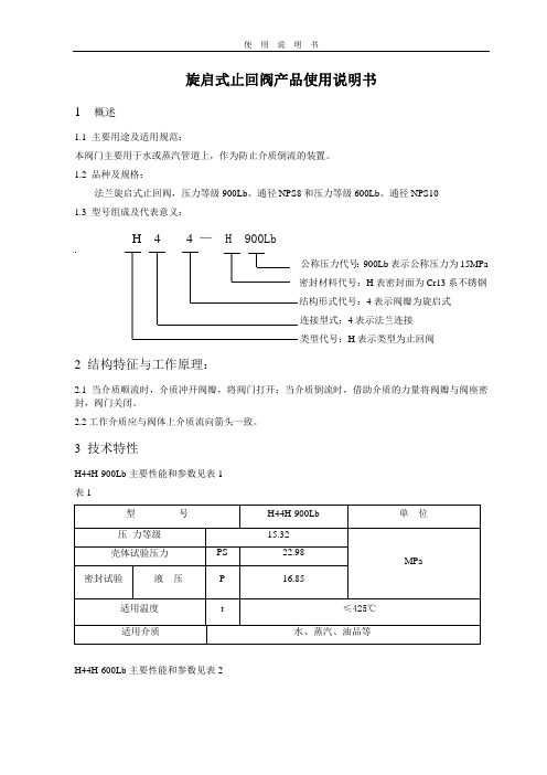
旋启式止回阀产品使用说明书1 概述1.1 主要用途及适用规范:本阀门主要用于水或蒸汽管道上,作为防止介质倒流的装置。
1.2 品种及规格:法兰旋启式止回阀,压力等级900Lb、通径NPS8和压力等级600Lb、通径NPS101.3 型号组成及代表意义:H 4 4 — H 900Lb公称压力代号:900Lb表示公称压力为15MPa密封材料代号:H表密封面为Cr13系不锈钢结构形式代号:4表示阀瓣为旋启式连接型式:4表示法兰连接类型代号:H表示类型为止回阀2 结构特征与工作原理:2.1当介质顺流时,介质冲开阀瓣,将阀门打开;当介质倒流时,借助介质的力量将阀瓣与阀座密封,阀门关闭。
2.2工作介质应与阀体上介质流向箭头一致。
3 技术特性H44H-900Lb主要性能和参数见表1表1H44H-600Lb主要性能和参数见表2表24 主要外形尺寸和连接尺寸见图一和图二。
5 主要零件的材料8”H44H-900Lb的主要零件材料见表3表3表46 保管、使用和安装6.1本阀门通道两端须堵密封盖,存放有干燥通风的室内。
长期存放,应经常检查,防止锈蚀6.2安装前,应将阀门清洗干净,并消除在运输过程中可能造成的缺陷。
6.3安装前,必须仔细核对阀门上的标志和铭牌是否符合使用要求。
6.4本阀门应安装在水平或垂直管道上的直立或侧卧位置,并便于检修和操作。
6.5本阀门在运行时应全开或全闭,不能作节流用,以免密封面受冲刷而加速磨损。
7 故障分析与排除方法见表3表3图一8”H44H-900Lb样图图二10”H44H-600Lb样图。
旋启式止回阀AWWA C508-2009讲解

前言重点内容
各种认证组织可以参与NSF / ANSI 61的产品认证。 各州或地方机构在其管辖范围内有权接受或授权认证机 构。认证组织可能因管辖权不同而不同。 附件一:“毒理学审查和评估程序”,NSF / ANSI 61没有规定关于污染物质最大允许水平(MAL)。MAL的未 指明的“不受监管的污染物”的列表是基于毒性测试指 南和风险表征方法(致癌物质)。使用附件的过程并不总 是相同的 ,这取决于证明方。 ! ANSI / AWWA C508没有解决添加剂的要求。因此,本 标准的用户应该咨询相应的拥有管辖权的国家或地方机, 这样是为了: !! 1.确定添加剂的要求,包括适用的标准。 2.确定各方提供认证产品的认证状态。 3.确定当前产品认证信息。
前言重点内容
1.3 验收 爬行和抓取 1985年5月,美国环境保护署 (构成)签订了一份合作协议由 NSF国际(NSF)发起的关于第三方自愿共识标准和直接及间接饮 水添加剂认证程序。原始财团的其他成员包括美国自来水厂协 会研究基金会(AwwaRF)和国家健康与环境协会。美国自来水 厂协会(AWWA)和国家饮用水的协会管理是在后来加入的。在 美国,当涉及到规范产品或与饮用水有关的标准,由各州的当地 机构可以选择比国家更加严格的标准。关于评估产品对健康的 影响和饮用水这类产品添加剂,州和地方机构可能使用不同的标 搜索词处理 准,包括: 1.由原来USEPA管理的咨询方案-Office of DrinkingWater,在 1990年4月7号停止了。 2.国家或地方机构的特殊政策 3.两个标准,饮用水处理化学品 - 健康电子FF学分,以及NSF/ ANSI61,饮用水系统组件 - 健康电子FF学分。 4.其他参考资料,包括AWWA标准,食品化学法典,水化学品 法典等,以及被国家或当地机构适当使用的标准。
旋启式止回阀的正确安装方法

旋启式止回阀的正确安装方法
旋启式止回阀是一种常用的管道阀门,它能够有效地防止介质倒流,
保护管道系统的正常运行。
正确安装旋启式止回阀可以确保其正常使用,以下是详细的安装方法:
一、准备工作
1. 根据管道系统的要求选择合适的旋启式止回阀型号和规格。
2. 检查旋启式止回阀的外观是否完好无损,是否符合相关标准和要求。
3. 清洗管道系统和旋启式止回阀内部,确保无杂质和污物。
4. 确定旋启式止回阀的安装位置和方向,并做好标记。
二、安装步骤
1. 将旋启式止回阀放置在安装位置上,并用螺栓或法兰将其固定在管
道系统上。
2. 检查旋启式止回阀与管道系统之间的连接是否紧密,无泄漏现象。
3. 调整旋启式止回阀的开关方向,使其符合管道系统的介质流动方向。
4. 打开管道系统中与旋启式止回阀相连的所有其他阀门,并排除空气
和气体等介质。
5. 缓慢打开旋启式止回阀,观察其运行情况,确保其能够正常开启和
关闭。
6. 检查旋启式止回阀的密封性能,确保其能够有效地防止介质倒流。
三、注意事项
1. 在安装旋启式止回阀时,应根据管道系统的要求选择合适的密封材
料和密封方式。
2. 在安装过程中,应注意旋启式止回阀与管道系统之间的连接是否紧密,并对连接部位进行必要的加固和支撑。
3. 在使用旋启式止回阀时,应定期检查其运行情况,并及时清洗和维护。
如有故障或损坏应及时更换。
4. 在安装前应仔细阅读相关操作说明书,确保按照正确的方法进行操作。
阀门安装操作维护手册
阀门安装操作维护手册阀门的保管与安装质量直接影响着阀门的使用,为了进一步加强阀门在运输、装卸、保管、安装、操作和养护各个环节的控制,保证阀门的质量,项目部在结合各生产厂家安装、操作和维修手册的基础上,编制了本项目使用的阀门操作维护手册,施工安装单位认真学习,并对照手册的要求安装、操作和维护阀门。
保证项目正常运行。
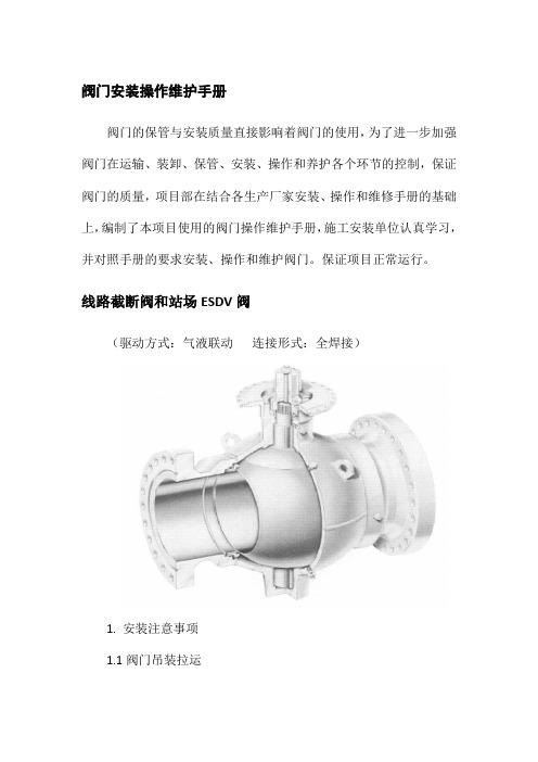
线路截断阀和站场ESDV阀(驱动方式:气液联动连接形式:全焊接)1. 安装注意事项1.1阀门吊装拉运1.1.1 应采用正确的方式吊装阀门,使阀体支撑负荷。
警告:其它凸出部件上。
支耳和阀门端颈为系吊链的正确位置,请切勿将吊链系于手轮、齿轮箱或执行器1.1.2如果阀门上装配有吊耳, 则应用吊耳吊装阀门。
1.1.3在吊装阀门期间应使阀门端部保护盖保持在原位。
只有当阀门安装完毕后,才可移去保护盖。
1.1.4 吊装时应逐个阀门吊装,不得多个阀门同时吊装。
阀门在摆放时禁止叠加。
警告:在吊装时,请注意保护阀门端面及阀门配件不受损坏,否则将导致阀门受损。
1.1.5 阀门拉运前要对阀门进行逐个检查,对存在外观缺陷、手轮变形、部件损坏的情况,施工单位可以拒绝拉运。
1.1.6阀门拉运时要对每台阀逐个固定,防止阀门在运输过程中倾倒、相互摩擦和碰撞。
1.1.7 阀门在拉运时要采取防雨措施。
1.1.8 阀门运抵现场后要设专人负责保管。
存放的场地要求平整,下铺上盖,排列整齐,小阀门可以放在货架上。
存放时注意保护好阀门封盖和法兰密封面。
禁止在存放期间闲杂人员对阀门进行开关。
阀门位置:球阀可安装在任何位置,阀门的任何一端均可作为上游端。
图1-正确的利用端颈吊装方式图 2 –正确的利用吊耳的吊装方式1.2焊接说明:阀门焊接连管前,前后管道应同轴,断面应平行。
带有支架的阀门必须放置在加固的基础之上,使得球阀不承受来自管线的附加应力。
阀门安装前管线必须吹扫干净,清除掉管道内的油污、焊渣和杂物。
1.2.1在预热、焊接或热应力释放时,距焊缝3″(75mm)以外阀体上的任何点处温度均不能超过400°F(200°C)。
阀门的安装维护和操作

安 装
• 闸阀不要倒装(即手轮向下),否则会使介质长 期留存在阀盖空间,容易腐蚀阀杆,而且为某些 工艺要求所禁忌。同时更换填料极不方便。 • 明杆闸阀,不要安装在地下,否则由于潮湿而腐 蚀外露的阀杆。 • 升降式止回阀,安装时要保证其阀瓣垂直,以便 升降灵活。 • 旋启式止回阀,安装时要保证其销轴水平,以便 旋启灵活。 • 减压阀要直立安装在水平管道上,各个方向都不 要倾斜。
维 护
• 对短期内暂不使用的阀门,应取出石棉填料,以 免产生电化学腐蚀,损坏阀杆。 • 对刚进库的阀门,要进行检查,如在运输过程中 进了雨水或污物,要擦试干净,再予存放。 • 阀门进出口要用蜡纸或塑料片封住,以防进去脏 东西。 • 对能在大气中生锈的阀门加工面要涂防锈油,加 以保护。 • 放置室外的阀门,必须盖上油毡或苫布之类防雨、 防尘物品。存放阀门的仓库要保持清洁干燥。
操 作
• 启闭阀门,用力应该平稳,不可冲击。某 些冲击启闭的高压阀门各部件已经考虑了 这种冲击力与一般阀门不能等同。 • 对于蒸气阀门,开启前,应预先加热,并 排除凝结水,开启时,应尽量徐缓,以免 发生水击现象。
操 作
• 当阀门全开后,应将手轮倒转少许,使螺 纹之间严紧,以免松动损伤。 • 对于明杆阀门,要记住全开和全闭时的阀 杆位置,避免全开时撞击上死点。并便于 检查全闭时是否正常。假如阀办脱落,或 阀芯密封之间嵌入较大杂物,全闭时的阀 杆位置就要变化。
• 填料与工作介质的腐蚀性、温度、压力不 相适应; • 装填方法不对,尤其是整根填料盘旋放入, 最易产生泄漏; • 阀杆弯曲 ; • 填料使用太久,已经老化 ;
2、关闭件泄漏 引起泄漏的原因有: 密封面研磨得不好;密封圈与阀座、阀瓣 配合不严紧;阀瓣与阀杆连接不牢靠;阀 杆弯扭,使上下关闭件不对中;某些介质, 在阀门关闭后逐渐冷却,使密封面出现细 缝,也会产生冲蚀现象;因焊渣、铁锈、 尘土等杂质嵌入,或生产系统中有机械零 件脱落堵住阀芯方向和位置
- 1、下载文档前请自行甄别文档内容的完整性,平台不提供额外的编辑、内容补充、找答案等附加服务。
- 2、"仅部分预览"的文档,不可在线预览部分如存在完整性等问题,可反馈申请退款(可完整预览的文档不适用该条件!)。
- 3、如文档侵犯您的权益,请联系客服反馈,我们会尽快为您处理(人工客服工作时间:9:00-18:30)。
2. Handling
2.1 Small valves may be lifted with slings, straps, or by hooking into end flanges. Large valves are furnished with lifting holes in the cover plate.
Fax: 281-894-1332 E-Mail: mandjvalve@
Web Site:
SPX Process Equipment reserves the right to incorporate our latest design and material changes without notice or obligation. Design features, materials of construction and dimensional data, as described in this bulletin, are provided for your information only and should not be relied upon unless confirmed in writing. Certified drawings are available upon request.
Installation, Operation, and Maintenance Manual for M&J Check Valves
I General information
1. The M&J swing check valve provides back flow control for piping systems. It is designed, manufactured, and tested in accordance with API-6D Q1 unless otherwise specified. The cast body design conforms to ANSI B16.34. Flanged end valve flanges are in accordance with ANSI B16.5 (24”and smaller) and MSS SP-44 (larger than 24”).
II Installation
Figure 1
1. Unpacking
3. Installation
1.1 All valves should be inspected on receipt for lost or damaged components.
1.2 Remove end connection protectors and thoroughly inspect valve interior for damage and/or foreign material. Remove all shipping supports.
Standard M&J check valves are designed for horizontal service. When vertical flow is intended, valves must be specifically ordered for that service.
3.1 For horizontal service, valves should be installed with the inlet and outlet at the same level. The cover plate should be facing upward to allow proper clapper action. The arrow on the body must be pointing in the direction of intended flow. For vertical flow up service, install the check valve with the clapper seat end down. The flow arrow should be pointing up.
Caution:
Always use handling equipment that is suitable for the valve weight. Follow good lifting practices. Take care not to damage valve or component assemblies.
4.1 Remove the valve cover plate. Remove and inspect cover seal replacing if damaged or showing excessive set. NOTE: M&J Valve recommends that the cover seal be replaced each time the cover is removed.
3.2 Clean the end connections and mating pipe prior to valve installation. It is recommended that the valve be supported properly to prevent strain and fatigue of the end connections.
2. Carbon steel weld end valves have end connections that are ready to be welded in the field. End preparations match specified mating pipe bores. Transition pieces are provided when specified.
When ordering spare parts, specify the valve serial number, valve size, ANSI pressure class, and type of service.
Inspection and Repair
Caution:
Body pressure MUST be relieved before any attempt is made to service internal parts of the swing check valve. Follow all safety procedures and appropriate regulations for handling the pipeline media.
3
III Maintenance
4. Maintenance
M&J swing check valves require minimal maintenance. Under normal operating conditions, no periodic maintenance is necessary. Recommended spare parts available through M&J Valve Company consist of clapper and cover seals, clapper, shaft, retainer pin, and arm. For valves having removable seats, seat rings and seat seals are also recommended.
4.2 Clapper removal.
4” and smaller
4.2.1 Lift clapper assembly out of valve hanger section.
ቤተ መጻሕፍቲ ባይዱ
4.2.2 Inspect clapper seal for damage. Replace if required. Inspect clapper for any imbedded foreign material. Remove as required. NOTE: Severely damaged clappers may require replacement.
4.2.3 Remove shaft. A 3/8”-16UNC tapped hole is provided in the shaft end to aid in shaft removal. To remove the shaft, screw a cap
screw or eyebolt into the tapped hole and pull on the screw. Clean and inspect shaft for damage before re-installing into valve. Replace shaft if required.
4.2.3 Clean and inspect clapper bushings.
6” and larger
4.2.1 Remove shaft-retaining plug. Larger valve sizes may have a bolted on cap.
4.2.2 Support clapper assembly and inspect arm hanger section of body noting bushing orientation between arm and body.
4.2.4.1 To replace clapper, remove retainer pin and nut then pull clapper from arm. Install new clapper onto arm shaft and replace retainer nut and pin.