5055使用说明
意大利(caleffi)卡莱菲自动排气阀 样本说明
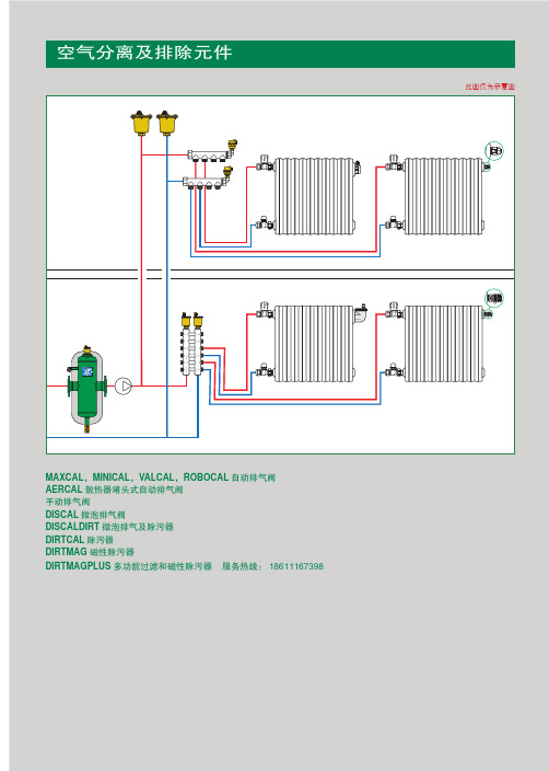
口径 3/8" M 1/2" M 无PTFE密封
编号 502730
2
5024
样本 01033
ROBOCAL
卡莱菲自动排气阀
阀体:黄铜 耐压:10 bar 最大排气压力:4 bar 耐温:115℃
口径 1/4" M 3/8" M
5025
样本 01033
ROBOCAL
卡莱菲自动排气阀
阀体:黄铜 耐压:10 bar 最大排气压力:4 bar 耐温:110℃ 带自闭阀
口径 3/4" 1" 1 1/4" 1 1/2" 2"
551 DISCAL
样本 01060
卡莱菲垂直管道安装式微泡排气阀
阀体:黄铜 内螺连接 耐压:10 bar 最大排气压力:10 bar 耐温:0 ~ 110℃
编号 551905 551906
口径 3/4" 1"
口径 3/8" M
包装 50
5026
样本 01033
ROBOCAL
卡莱菲自动排气阀
阀体:黄铜 耐压:10 bar 最大排气压力:6 bar 耐温:115℃
口径 3/8" M 1/2" M
5027
样本 01033
ROBOCAL
卡莱菲自动排气阀忧
阀体:黄铜 耐压:10 bar 最大排气压力:6 bar 耐温:110℃ 带自闭阀
一个系统中可分离及排除的气体量与系统的流速和压力相 关,当流速和压力降低时排气量也随之上升。
在系统按可允许最高流速循环25次后,几乎所有的空气均 从微泡排气阀中排除,排气比例因系统压力不一而略有区别。
剩余的少量气体将在系统接下来正常循环中排除。在流速 更低或温度更高的情况下,排气量还将更高。
最新505中文操作说明

最新505中文操作说明转速控制系统1、概述本机组采用WOODWARD公司生产的505调速器作为转速控制系统。
WOODWARD 505是以微处理器为基础的汽轮机用数字式调节器,控制精度NEMA D级,响应时间:40ms。
WOODWARD 505是一种现场可组态且与操作人员控制屏为一体式的汽轮机调速器。
综合性的操作人员控制屏包8.4英寸液晶显示屏和键盘。
在操作时每个程序步都会在显示屏中显现,机组运行时,显示屏上可同时看到设定参数的实际值和给定值。
505采用选项屏(菜单)驱动程序软件,使用户能便捷地按机组特性自主在现场进行组态。
505调节器的操作主要有三种模式:配置模式、校准模式和运行方式.✧配置模式是指在汽轮机停机状态下,针对具体应用对505进行配置,通常一旦调节器完成组态就不再使用配置模式。
✧校准模式用于强制信号输出,以校准信号和现场设备,此模式下执行机构、模拟输出和继电器输出可以手动控制,为进入此模式调速器必须停机且汽轮机转速为零。
✧运行模式是指调节器组态后从机组起动到停机整个过程的操作。
此外,还有一种模式是服务方式,它可在505接通电源后的任何时间内联机对程序或设置参数进行调谐,进入服务模式需要相应的用户级别,只有服务用户级别和配置用户级别才能进入服务模式,服务模式内调整的参数可以影响系统的性能,建议在专业人员指导下修改参数,如因私自更改服务模式下参数导致汽轮机性能不稳定,汽轮机厂家概不负责。
505设置不同的用户级别来使用户获得对应的操作权限,这些密码旨在防止未经授权或未经培训的人员访问并作出对汽轮机或相关过程造成损坏的更改,具体如下:✧监视用户级别仅有查看的访问权限,不要求密码。
✧操作员用户级别允许对汽轮机进行控制,前面板指令可用,更改设定值及停机操作,用户密码为wg1111✧服务用户级别,除操作员用户级别权限外,可以调整菜单参数,用户密码为wg1112;✧配置用户级别,除服务用户级别权限外,还可以更改程序参数,用户密码为wg1113;必要时用户可自行更改原有口令,口令修改方法见WOODWARD505说明书第2册“Change Password”一节说明。
2085_VAS6150A文档说明和恢复指南

VAS 6150 诊断用笔记本电脑文档提示和恢复指南VAS 6150 基础 CD 16 以上V2.00VAS 6150 诊断用笔记本电脑___________________________________________2 - 16 文档提示和恢复指南VAS 6150 基础 CD 16 V2.00 以上保留所有权利VAS 6150 诊断用笔记本电脑_______________________________________________文档提示和恢复指南 3 - 16 保留所有权利 VAS 6150 基础 CD 16 V2.00 以上目录1. 简介 (4)1.1缩写与概念 (4)2. 文档提示 (5)2.1 Panasonic CF-52 型操作说明........................................................................5 2.2 调试和拆封说明.............................................................................................5 2.3 服务信息........................................................................................................5 2.4 自诊断手册....................................................................................................5 2.5 诊断软件安装指南 – 基础 CD 或 VAS-PC .....................................................5 2.6 VAS 5054A/VAS 5055 设备手册...................................................................5 2.7 Utility CD.......................................................................................................5 2.8 简要安装指南.................................................................................................6 2.9软件手册 – VAS-PC (6)3. 系统还原(恢复) (7)3.1 概述...............................................................................................................7 3.2 第 1 步:启动 BIOS 系统(设置)................................................................8 3.3 第 2 步:输入 BIOS 密码...............................................................................9 3.4 第 3 步:选择 BIOS 菜单“Exit ”(退出)...................................................9 3.5 第 4 步:确认系统还原................................................................................10 3.6 第 5 步:系统还原进程................................................................................10 3.7 第 6 步:语言设置.......................................................................................10 3.8 第 7 步:Windows 下的语言和键盘设置......................................................12 3.9 第 8 步:VAS-PC 软件安装.........................................................................15 3.10 第 9 步:安装软件补丁“VAS_5055_prep ”............................................15 3.11 第 10 步:启动并安装基础 CD 软件.........................................................15 3.12第 11 步:连接和配置诊断仪 VAS 5054A 或诊断接口 VAS 5055 (16)VAS 6150 诊断用笔记本电脑___________________________________________4 - 16文档提示和恢复指南VAS 6150 基础 CD 16 V2.00 以上 保留所有权利1. 简介提示本手册内容用于提示适用的文档并说明诊断笔记本电脑 VAS 6150 的安装,特别是恢复功能。
思科 AnyConnect 安全移动客户端 4.0.x 版本说明说明书

Apple iOS 版 Cisco AnyConnect 安全移动客户端 4.0.x 版本说明Apple iOS版AnyConnect版本说明2Apple iOS移动设备版AnyConnect2可用于Apple iOS的AnyConnect版本2支持的Apple iOS设备3在Apple iOS上升级AnyConnect4Apple iOS版AnyConnect4.0.07x的新功能5Apple iOS版旧版AnyConnect4.0.05x的新功能6Apple iOS版AnyConnect功能表11自适应安全设备要求14其他思科头端支持14已知问题和限制15AnyConnect Mobile相关文档21Revised: October 26, 2017,Apple iOS版 AnyConnect 版本说明Apple iOS 移动设备版 AnyConnectAnyConnect安全移动客户端为远程用户提供与思科ASA5500系列的安全VPN连接。
通过该客户端,用户能够无缝、安全地远程访问企业网络,使安装的应用可如同直接连接到企业网络一般进行通信。
AnyConnect支持通过IPv4或IPv6隧道连接到IPv4和IPv6资源。
本文档适用于AnyConnect安全移动客户端和自适应安全设备(ASA)5500的管理员,为思科AnyConnect安全移动客户端管理员指南,版本4.0提供补充,并为Apple iOS设备上运行的AnyConnect提供版本特定的信息。
该AnyConnect应用仅在Apple iTunes App Store中提供。
思科不分发AnyConnect移动版应用,您也不能从ASA部署该移动应用,但是,您可以从ASA为桌面设备部署其他版本的AnyConnect,并同时支持此移动版本。
AnyConnect 移动版支持策略思科支持应用商店当前提供的AnyConnect版本;但是,修复和增强功能仅在最新发行的版本中提供。
Hunter 50952 50980吊扇安装手册说明书
Installation ManualModel: 50952 Matte White 50980 Matte BlackFan weight ±2 lbs: 24.0 lbs (10.9 kg)H o m e K i t S t i c k e rc.1 - All wiring must be in accordance with national and local electrical codes ANSI/NFPA 70. If you are unfamiliar with wiring, use a qualified electrician.c.2 - Use only Hunter replacement parts.This equipment has been tested and found to comply with the limits for a Class B digital device, pursuant to part 15 of the FCC Rules. These limits are designed to provide reasonable protection against harmful interference in a residential installation. This equipment generates, uses and can radiate radio frequency energy and if not installed and used in accordance with the instructions may cause harmful interference to radio communications.However, there is no guarantee that interference will not occur in a particular installation. If this equipment does cause harmful interference to radio or television reception, which can be determined by turning the equipment off and on, the user is encouraged to try to correct the interference by one or more of the following measures:• Reorient or relocate the receiving antenna.• Increase the separation between the equipment and receiver.• Connect the equipment into an outlet on a circuit different from that to which the receiver is connected.• Consult the dealer or an experienced radio/TV technician for help.Caution: modifications not approved by the party responsible for compliance could void user’s authority to operate the equipment.This device complies with Part 15 of the FCC Rules. Operation is subject to the following two conditions: (1) This device may not cause harmful interference, and (2) this device must accept any interference received, including interference that may cause undesired operation.This product conforms to UL Standard 507.We recommend that you pull everything out of the box and lay it out. We have grouped the drawn components below with the hardware you’ll need for those parts. The screws below are drawn to scale to make it easier to identify what piece of hardware is needed to install each component.Note:If you have an angled or vaulted ceiling:1. You will need a longer downrod. (sold separately at )2. If your ceiling angle is greater than 34°, you will also need anAngled Mounting Kit. (Sold separately at )If you have a flat ceiling:Hang your fan by a standard downrod. Some fans comewith a shorter downrod for a Low Profile installation.Standard Mountingbracket with hardware found in the hardware bag.Hunter Pro Tip:You have two options for installation. Pick which one works best for your location. Remove any existingPass all wires to one side of horizontal bar in downrod assembly. Hand tightenHanging the FanS l i d e c a n o p y o v e r d ow nr o d a n d w ir e s .Place the downrod ball into the slot in the ceiling bracket.NOTICETo prevent damage to fan, ALWAYS lift holding either the fan housing or the downrod.Note:DRSKY-01 r091420We know wiring is hard. Let’s make it easier.bag)Follow these steps to get your fan wired quickly and safely. Follow the route below that best matches your wall switch setup. If you are unfamiliar with wiring or uncomfortable doing it yourself, please contact a qualifi ed electrician.Insert the two canopy screwsfound in the hardware bag. Put the blade washers, found in the1886Installing the Glass NOTE: Check to ensure proper engagement.Attach the globe by lifting and turning clockwise one third of a full turn of the glass until it stops.WARNINGGLASS FALL HAZARDTo prevent SERIOUS INJURY or DEATH , make sure that glass is properly secured.Install the included bulbs into the sockets. When necessary, replace with bulbs of same wattage.Lift the globe and align the notches in the globe with the tabs in the light kit.NotchTabFan style may vary.Note:Assembling the Light KitInsert the third screw, found in the hardware bag, into place and then tighten all three screws.Partially install two light kitassembly screws, found in the hardware bag, halfway into the motor housing as shown. It does not matter which two screw holes you choose.Feed the wire plugs through the center hole of the upper switch housing, then wrap keyhole slots around the screws and twist counterclockwise.WARNINGFAN FALL HAZARDMake sure all screws are tight to secure the light fixture.2 of 31 of 3Assembly ScrewAssembly Screwbagbag2 of 31 of 3Light Kit ScrewLight Kit ScrewbagbagPartially install two of the light kit screws found in the bag. It does not matter which two screw holes you choose. Connect the single-pin connectors from the LED assembly to the connectors from the fan. Connect the white wires together. Connect the blue and black wires together.Align the keyhole slots in the light kit housing with the two screws. Make sure all the wires from the fan and the light kit are snug inside the center of the light kit, not pinched in between the upper switch housing and the light kit or hanging out of the sides.Turn the light kit counterclockwise until the light kit screws are firmly situated in the narrow end of the keyhole slots. Install the third screw and tighten all three screws securely.Fan style may vary.Note:SIMPLEconnect connects to available 2.4 GHZ WiFi networks.Launch the app.Follow the onscreen prompts to set up your fan.Download the app:Visit your app store and search “Simpleconnect ™ 2.0” to find the app.Need to install the app later?When ready, turn the wall switch off and then on. Wait three minutes before downloading the app.Hunter Pro Tip:Use of the HomeKit logo means that an electronic accessory has been designed to connect specifically to iPod, iPhone, or iPad, respectively, and has been certified by the developer to meet Apple performance standards. Apple is not responsible for the operation of this device or its compliance with safety and regulatory standards. Please note that the use of this accessory with iPod, iPhone, or iPad may affect wireless patible with iOS 7.1 or higher / Android 4.3 or higher Android and Google Play are trademarks of Google Inc.Apple logo is a trademark of Apple, Inc.App store is a service mark of Apple, Inc.If you need a different downrod length follow these steps:Follow steps 1-5 to remove standard downrod pipeFollow steps 6-10 to reassemble with new downrodthe downrod assembly unassembled.Assembled downrod should look like this11Hunter Pro Tip:Hunter Fan Company grants this limited warranty to the original purchaser of this Hunter ceiling fan. This document can be found at . Thank you for choosing Hunter!How Can Warranty Service Be Obtained?Proof of purchase is required when requesting warranty service. The original purchaser must present a sales receipt or other document that establishes proof of purchase. Hunter, at its sole discretion, may accept a gift receipt. To obtain service, contact Hunter Fan Company online or by phone./Support/Contact-Us/1-888-830-1326Please do not ship your fan or any fan parts to Hunter. Delivery will be refused.What Does This Warranty Cover?Motor — Limited Lifetime WarrantyIf any part of your ceiling fan motor fails during your ownership of the fan due to a defect in material or workmanship, as determined solely by Hunter, Hunter will provide you with a replacement fan free of charge.* The foregoing limited warranty applies only to the motor itself and does not apply to electronic controls – such as remote control transmitters, remote control receivers, or capacitors – used in conjunction with the motor. Such electronic control items are included in the one-year limited warranty below.Other — One-Year Limited WarrantyExcept as otherwise indicated throughout this warranty, if any part of your Hunter ceiling fan fails at any time within one year of the date of purchase due to a defect in material or workmanship, as determined solely by Hunter, Hunter will provide a replacement part free of charge.*Light Kits — Warranty May VaryLight kits are included in the one-year limited warranty. However, you may qualify for additional warranty coverage if your fan includes one of the following:• LED Light Kits — Three-Year Limited WarrantyIf your LED light kit module (not including glass components) or LED bulb fails at any time within three years of the date of purchase due to a defect in material or workmanship, as determined solely by Hunter, Hunter will provide a replacement part free of charge.** If no replacement product/part can be provided for your fan, we will provide a comparable or superior replacement product/part at the sole discretion of Hunter.What Does This Warranty NOT Cover?Labor Excluded. This warranty does not cover any costs or fees associated with the labor (including electrician’s fees) required to install, remove, or replace a fan or any fan parts. There is no warranty for light bulbs (except where otherwise noted); remote control batteries; fans purchased or installed outside the United States; fans owned bysomeone other than the original purchaser; fans for which proof of purchase has not been established; fans purchased from an unauthorized dealer; ordinary wear and tear; minor cosmetic blemishes; refurbished fans; and fans that are damaged due to any of the following: improper installation, misuse, abuse, improper care, failure to follow Hunter instructions, accidental damage caused by the fan owner or related parties, modifications to the fan, improper or incorrectly performed maintenance or repair,improper voltage supply or power surge, use of improper parts or accessories, failure to provide maintenance to the fan, or acts of God (e.g. flood).ORIGINAL PURCHASER’S SOLE AND EXCLUSIVE REMEDY FOR A CLAIM OF ANY KIND WITH RESPECT TO THIS PRODUCT SHALL BE THE REMEDIES SET FORTH HEREIN. HUNTER FAN COMPANY IS NOT RESPONSIBLE FOR CONSEQUENTIAL OR INCIDENTAL DAMAGES, DUE TO PRODUCT FAILURE, WHETHER ARISING OUT OF BREACH OF WARRANTY , BREACH OF CONTRACT, OR OTHERWISE. Some States do not allow the exclusion or limitation of incidental or consequential damages, so the above limitation or exclusion may not apply to you.ANY IMPLIED WARRANTIES OF MERCHANTABILITY OR FITNESS FOR A PARTICULAR PURPOSE APPLICABLE TO THIS PRODUCT ARE LIMITED IN DURATION TO THE PERIOD OF COVERAGE OF THE APPLICABLE LIMITED WARRANTIES SET FORTH ABOVE. Some States do not allow limitations on how long an implied warranty lasts, so the above limitation may not apply to you.How Does State Law Affect Warranty Coverage?This warranty gives you specific legal rights. You may also have other rights which vary from state to state.Limited Lifetime WarrantyFan Doesn’t Work • Make sure power switch is on.• Check the circuit breaker to ensure the power is turned on.• Make sure the blades spin freely.• Check the plug connection in the switch housing.Excessive Wobbling • Make sure the blades are properly installed on the blade iron posts.• Turn the power off, support the fan carefully, and check that the hanger ball is properly seated.• Use the provided balancing kit and instructions to balance the fan.Remote Control of Fan is Erratic • Make sure the battery is installed correctly.• Install a fresh battery.Noisy Operation• Make sure the blades are properly installed.• Check to see if any of the blades are cracked. If so, replace all of theblades.Multiple Remote Issues • If you have multiple remotes or multiple remote-controlled fans installed on the same circuit breaker and you are experiencing interference or faulty operation of your remote controls, please go to/FAQs and click “How do I properly install multiple remote-controlled fans?” for information on how to correct this issue.。
ZOOM505ii中文说明书

ZOOM 505ii中文说明书介绍感谢您选择了ZOOM505 II(以下简称” 505 II”).请务必花点时间仔细阅读本手册,以便充分开发本设备的性能,确保获得最佳使用效果.保存好手册\保修卡以及所有的文件,以备将来查询.目录安全警告 (2)功能 (3)本手册中用到的条目 (4)用电池给本设备供电 (5)控制和功能 (6)选择演奏音色 (8)使用调音器功能 (10)编辑音色 (12)储存/复制音色 (14)改变音色调出模式 (16)使用选项踏板 (18)恢复原厂缺省设置 (19)连接效果模块 (20)效果类型和参数 (21)规格 (31)使用警告 (31)音色表排除故障.P.2.安全警告在本手册中,使用明显的警告和注意符号作出提示,防止发生事故.这些符号的含义如下所示: !警告--这个符号表示有特别危险的事项.如果用户忽略了这个符号,在操作设备时发生失误,则会发生严重的伤害甚至死亡.!!注意--这个符号表示有危险的事项.如果用户忽略了这个符号,在操作设备时发生失误,则可能导致身体受到伤害或损坏设备.!警告--关于电源*因为本设备的功率损耗相当高,所以,我们建议您最好随时使用AC电源转换器.用电池作为设备的电源时,只能使用碱性电池.AC转换器的操作*一定要使用9V DC,300MA的AC转换器供电,并且应装备有"中心负极"插头(ZOOM AD-0006).如果不使用指定类型的转换器,则可能会损坏设备或发生安全事故.*连接AC转换器时,只能使用适合转换器额定电压的AC插板.*从AC线板上取下AC转换器时,要抓住AC转换器,而不能拉连接线.*如果长时间不使用设备,应将AC转换器从插线板上取下.安装电池*请使用IEC R6 (尺寸为AA),1.5V的电池(碱性/锰).*不能用505 II来给电池充电.特别要注意电池上的标签,一定要选择合适的类型.*如果准备长期不使用505 II,请取出设备内的电池.*如果电池发生泄漏,请仔细擦净电池舱和电池两端,清除掉所有电池液体的残留物.*使用设备时,应关好电池舱的盖子.!!注意环境使用505II时,不能将它暴露于下列环境中:*温度过高或过低的地方*湿度较高或潮湿的地方*灰尘或沙粒太多的地方*特别震动和摇晃的地方!!注意操作*505 II属于精密的乐器,除了踏板之外,不要用脚或物体去碰设备的其他部分,操作时不要太使劲.*小心,不要让外部物体(纽扣或针等物品)或液体进入设备中*连接之前,一定要先关闭所有设备的电源.*移动设备之前,记得关闭电源,断开所有线缆和AC转换器.!!注意变更请不要打开505 II的外壳,或者试图用任何方式修改本产品,因为这样会损坏设备.P.3.功能505 II是一个精密复杂的吉他多重效果处理器,它具有下列功能和选项:*高级演奏性能505 II仅用了接近于单块效果器的价位,却拥有33个经过各种组合和调色的效果.每个音色中总共可组合9种效果(包括ZNR和音箱模拟器).设备的内存中有36个可以重新写入的音色,还可以不受锁定限制演奏.*直观的用户界面用户界面彻底重新设计.有大型的开关和按钮,以及一个旋转选择器,用它们来操作设备就非常简单.可以即刻调出自己想要的效果,不会发生混乱.*内置半音阶自动调音器这项综合调音功能可以让你在台上迅速而准确地给乐器调音.*两种供电方式,可以随处使用两种供电方式,既可以用AC转换器供电,也可以用四节IEC R6 (尺寸为AA),1.5V的电池供电.使用电池的连续工作时间是:锰电池为8小时 *** 59;碱性电池为28小时.*兼容脚踏开关和踏板在CONTR OL IN插口中可以连接一个脚踏开关选项(FS01)或者表情踏板(FP01/FP02).踏板开关用于快速切换音色,表情踏板则可实时调节音量或效果的音质.*改进后的505的升级换代产品这块效果器继承了ZOO M机型505的非常成功的音色特征,体形小巧,价位较低.而且,它合并了九种新的效果,包括使用了很久的技术失真效果,舞台常用效果和特殊效果.P.4.本手册中用到的条目这一部分解释某些重要的条目,它们在505II的文本中经常使用.*效果模块如下面的图表所示,你可以将505 II看作是几个单块效果器的组合.里面的每个效果就是一个效果单块.除了组成压缩器效果(COMP)或失真效果(DIST)的模块之外,505 II上还有一个ZNR(ZOOM降噪)和一个吉他音箱模拟器.象效果深度这样的参数都可以在各个模块上分别调节,而且各个模块都可以随意打开或关闭.输入-压缩-失真-均衡-降噪-音箱模拟器-调制器-延迟/混响-输出*效果类型在每个效果模块中,都有几个各不相同的效果,这就是效果类型.例如:调制效果模块(MOD)由合唱\边缘声\音高位移器和其他效果类型组成.一次只能选择其中的一个.效果类型通常也用来指代一种效果.*效果参数所有效果模块都有各种可以调节的参数.把效果模块看作一个单块效果设时,参数就可以看作是设备上面的控制旋钮.改变参数设置,将会改变效果深度等条目,从而改变音质特征.*音色(音图)在505 II中,把可以储存到设备中和从设备中调出的效果模块组合称为音色.音色的信息包括每个效果模块的开/关状态,每个模块中的效果类型,以及效果的参数设置.505 II的内存可储存36个音色.*音库把六个音色分为一组,这样的音色组称为音库.505 II中共有六个音库,命名为A到F.每个音库中的音色按1到6来编号.在505 II中,用下列格式来指定一个音色:"A1"-它表示的是音库A中编号为1的音色.以此类推,"B6"则是音库B中编号为6的音色.P.5.音库A音色1音色2音色3音色4音色5音色6音库B音色1音色2音色3音色4音色5音色6音库C音色1音色2音色3音色4音色5音色6音库D音色1音色2音色3音色4音色5音色6音库E音色1音色2音色3音色4音色5音色6音库F音色1音色2音色3音色4音色5音色6*播放模式/编辑模式505 II的内置状态指的就是操作模式.两个主要模式就是播放模式-在这种模式下选择音色,并用这种音色来演奏乐器 *** 59;编辑模式-在这种模式下修改效果.用[PLAY/EDIT]选择键来切换播放模式和编辑模式.使用电池给设备供电1.将505 II翻转过来,打开设备底部的电池舱盖.按住插销,让它松动,然后打开舱盖.2.把四节新的I EC R6(尺寸为AA)电池放进电池舱.按相同的方向插入所有电池.四节IECR6(尺寸为AA)电池所有电池极性应一致。
网屏5055维修手册(一)

⽹屏5055维修⼿册(⼀)⽹屏5055维修⼿册(⼀)剑神FT-R5055激光照排机报错对应表1 SET FILM MAG 供⽚盒没装,装供⽚盒2 SET COLLECT BOX 收⽚盒没装,装收⽚盒3 CHANGE COL BOX 收⽚盒胶⽚没取完,将胶⽚取出4 MATERIAL EXIST 胶⽚位置错误,调整胶⽚位置5 PLEASE CUT FILM 被排出的胶⽚留在机器内,执⾏CUT命令6 PLEASE SET FILM 没装胶⽚,执⾏SET命令7 PLEASE LOAD FILM 没装胶⽚,执⾏LOAD命令8 FILM EMPTY1 胶⽚⽤完,取出剩余胶⽚,装⼊新的胶⽚9 FILM EMPTY2 胶⽚⽤完,取出剩余胶⽚,装⼊新的胶⽚10 SHUT THE DOOR 胶⽚⽤完,取出剩余胶⽚,装⼊新的胶⽚11 RESTART DL-MIDE 重新启动DOWNLOAD模式12 FILM EMPTY3 胶⽚⽤完,取出剩余胶⽚,装⼊新的胶⽚13 WIDTH NOT ENORGH 计算机设定的曝光宽度⼤于胶⽚宽度⼤于胶⽚宽度,请输⼊正确的数值14 FAN1 TROUBLE 进风扇1坏15 FAN2 TROUBLE 进风扇2坏16 FAN3 TROUBLE 进风扇3坏17 FAN4 TROUBLE 进风扇4坏18 AFP POWER OFF1 AFP 电源关上,请打开19 AFP NOT READY AFP 正在启动,请稍等20 AFP POWER OFF2 AFP 停⽌,打开电源(备⽤)21 AFP BUSY AFP正忙,请稍等22 DOWNLOAD ERROR 下载任务失败23 MODE MIXMATCH 启动模式错误,检查MCON板上的DIP开关24 CHANGE FILM MAG 更换胶⽚盒25 PUNCH DUST FULL 打孔碎⽚满了,清理掉26 IMPUT DATA ERROR 输⼊数据不符合曝光条件,检查输⼊数据27 LOADING ERROR 胶⽚在起始感应器位置错误,调整其位置28 FILM FAM1 胶⽚在中间感应器位置错误,调整其位置29 FILM FAM2 胶⽚在组合感应器位置错误,调整其位置30 FILM FAM3 胶⽚在排放感应器位置错误,调整其位置31 FILM FAM4 胶⽚停在排放感应器位置错误,调整其位置32 FILM FAM5 胶⽚在末端感应器位置错误,调整其位置33 FILM FAM6 胶⽚停在末端感应器位置错误,调整其位置34 FILM FAM7 胶⽚传送时收⽚盒没⼯作,调整其位置35 FILM FAM11 胶⽚停在排放感应器位置错误,调整其位置36 FILM FAM12 胶⽚在末尾感应器位置错误,调整其位置37 FILM FAM13 胶⽚停在末尾感应器位置错误,调整其位置38 FILM FAM14 胶⽚掉进AT单元,调整其位置39 MACHINE ERROR1 裁切部分错误(感应器都开或关)40 MACHINE ERROR2 裁切部分错误(前切感应器没打开)41 MACHINE ERROR3 裁切部分错误(后切感应器没打开)42 MACHINE ERROR4 后缓冲导引错误(后缓冲导引感应器没关上,后缓冲导引没开)43 MACHINE ERROR5 后缓冲导引错误(后缓冲导引感应器没打开,后缓冲导引没关)44 MACHINE ERROR6 前缓冲导引错误(两个或多个前缓冲导引感应器都是打开的)45 MACHINE ERROR7 前缓冲导引错误(当前缓冲导引打开时,感应器没开)46 MACHINE ERROR8 前缓冲导引错误(当前缓冲导引关上时,感应器没开)47 MACHINE ERROR9 前缓冲导引错误(当前缓冲导引在REWIND位置时,感应器没开)48 MACHINE ERROR10 AT导引感应器没关上,AT导引感应器没关上,AT导引没开)49 MACHINE ERROR11 AT导引感应器没关上,AT导引感应器没打开,AT导引没关)50 MACHINE ERROR12 曝光过程错误(EXP-END信号没探测到)51 MACHINE ERROR13 ND转换单元错误(ND转换感应器没有打开或关上)52 MACHINE ERROR14 起始曝光错误(页⾯信号没打开)53 MACHINE ERROR15 起始曝光错误(连线启动脉冲信号没探测到)54 MACHINE ERROR16 棱镜错误(没有探测到棱镜加速信号)55 MACHINE ERROR17 前缓冲棍探测传感器错误(感应器全开)56 MACHINE ERROR18 前缓冲棍探测传感器错误(当前缓冲棍抬起时,感应器没开)57 MACHINE ERROR19 前缓冲棍探测传感器错误(当前缓冲棍下降时,感应器没关)58 MACHINE ERROR20 前打孔单元错误(前打孔感应器没开,打孔单元不下降)59 MACHINE ERROR21 前打孔单元错误(前打孔感应器没关,打孔单元不上升)60 MACHINE ERROR22 尾打孔单元错误(前打孔感应器没开,打孔单元不下降)61 MACHINE ERROR23 尾打孔单元错误(前打孔感应器没关,打孔单元不上升)62 MACHINE ERROR24 收⽚盒位置错误63 MACHINE ERROR30 电源接通时,机器初始化错误64 STOP 按了停⽌键,操作停⽌65 AFP ERROR1 胶⽚在传接到冲机的过程中卡住66 AFP ERROR2 胶⽚在冲机⾥卡住67 AFP ERROR3 冲机马达停⽌68 AFP ERROR4 冲机门打开了,请关上69 AFP ERROR9 冲机显影温度错误70 AFP ERROR10 冲机定影温度错误71 AFP ERROR11 冲机烘⼲温度错误72 AFP ERROR12 冲机显影槽液⾯下降73 AFP ERROR13 冲机定影槽液⾯下降74 AFP ERROR14 冲机清洗液槽液⾯下降75 AFP ERROR17 冲机显影液补充槽液⾯下降76 AFP ERROR18 冲机定影液补充槽液⾯下降77 AFP ERROR19 冲机清洗液补充槽液⾯下降78 AFP ERROR20 冲机⽔补充槽液⾯下降79 AFP ERROR22 冲机废显影槽液⾯达到上限80 AFP ERROR23 冲机废定影槽液⾯达到上限81 AFP ERROR24 冲机废清洗槽液⾯达到上限82 AFP WARNING9 更换显影过滤器83 AFP WARNING10 更换定影过滤器84 AFP WARNING11 更换清洗过滤器185 AFP WARNING12 更换清洗过滤器286 AFP WARNING13 更换空⽓排空过滤器87 SERIAL ERROR11 AFP传输错误(AFP SIDE)88 SERIAL ERROR10 AFP传输错误(FT-R SIDE)89 I/F ERROR 1 AFP信息传输错误(SCSI BUS),重启系统90 SERIAL ERROR01 界⾯单元RS信息传输错误,重启系统91 SERIAL ERROR00 MCON板的RS信息传输错误,重启系统92 IMAGE ERROR SCSI信息传输错误(曝光图⽂先于硬盘读出数据),重启系统93 I/F COM ERROR1 SCSI信息传输错误(CDB参数错误),重启系统94 I/F COM ERROR2 SCSI信息传输错误(没出息接收到操作命令),重启系统95 I/F COM ERROR3 CDB错误(SCSI)重启系统96 I/F ERROR2 SCSI错误(逻辑单元除0都选择)任务97 I/F ERROR3 SCSI传输命令错误,重启系统98 I/F ERROR4 SCSI传输命令错误,重启系统99 DISK**ERROR HDD错误100 DISD**UNMORNTED HDD没执⾏。
5055说明书
SCSI-ID
6
BUZZER
SCSI-ID设定:一般设定6, 不用更改
<SCSI-ID BUZZER>
MENU
ENT
BUZZER
ON
BUZZER: 此设定是控制在按键时是否发出“Beeps”的声音以做提醒。
MENU
ENT
COND SPC WIDTH
CUT-L SPC 1mm LINE WIDTH 0.1mm
当选用裁线后,需设定以下两个参数 CUT-L WIDTH : 裁剪 线开 度 ,设 定 范围 为0.1到3.0毫 米 CUT-L SPC :影 像未 段 至裁 剪 的距 离, 可调范 围从1至99毫 米 。 每 一图像 曝光长 度为 : 页与 页 设定 之 间空 间+图 像 长度+裁剪 线空 间+裁 切 线宽 度 。
一条线代表:1000dpi 两条线代表:1200dpi 三条线代表:1500dpi 四条线代表:1800dpi 五条线代表:2400dpi 六条线代表:3000dpi
线条数目是代表 分辨率的设定
曝光值过大
设 定 值+10
50% 100%
设 定 值+5 设定值 设 定 值-5
设 定 值-10
查询控制版的版本
<CUT CUT-COND FF
L OA D:上 片 功能 , 将软 片 送进 开 始曝 光 的位 置。 SET:这装片功能是将大约20cm的软片裁掉,送往冲片机或者收片盒,
以去掉已走光的部分。 R EM O VE: 收 片功 能 ,将 软 片收 回可 取 出的 位 置。 CUT-COND:设定在裁片前先送出指定尺寸的软片。 CUT:裁片功能,将已曝光的软片裁切送往冲片机或者收片盒。 F f: 裁 片前 先 送出 指 定尺 寸 的软 片 。
诊断接口vas 5055 说明书
诊断接口 VAS 5055VAS 5055 操作手册 V1.03目录1通用说明3 1.1操作手册的使用3 1.2特性和使用范围3 1.3供货范围4 1.4说明4 2VAS 5055 的使用范围及应用5 2.1特性5 2.2系统要求5 2.3系统结构6 3安装和投入运行7 3.1安装诊断应用程序7 3.2将 VAS 5055 连接到车辆上 12 3.3VAS 5055 的连接和安装 13 4带诊断应用程序的 VAS 5055 的应用 15 5诊断接口配置工具 16 6常见问题 (FAQs) 18 7附录19 7.1VAS 5055 技术数据 19 7.2状态指示灯19 7.3车辆插头的布置 20 7.4自检21 7.5EC 合格声明22 7.6许可23 7.7安全提示24 7.8支持241 通用说明1.1 操作手册的使用此操作手册包含无线诊断头 VAS 5055 的安装、配置和运行方面的信息VAS 5055 的技术规定(见附录)VAS 5055的操作手册在大众公司诊断工具安装 CD 中的帮助目录下。
安装后可在诊断应用程序的开始菜单程序组中通过选项VAS5055 文献找到本手册的不同语言版本。
说明由于我们对软件的进一步开发,屏幕上显示出的用户对话框可能与本文件中的图示有细微差别。
除德语版本外,本手册中的图示均以英语标注。
由于诊断应用程序设有多种语言,所以很多情况下,在安装过程中用户对话框均以各操作系统所采用的语言显示。
如果不支持操作系统中的语言,则显示英语。
1.2 特性和使用范围使用诊断接口 VAS 5055,大众公司的诊断应用程序可以通过 USB 接口便捷地访问所安装的车辆系统。
VAS 5055 结构紧凑且带内置诊断插头,非常适合用于售后服务、生产和试车领域。
特殊性能:适用于安装了诊断应用程序 VAS 5163 的 PC 的 USB 接口外壳带有内置诊断插头VAS 5055 内的诊断记录可靠、有效由车辆进行供电,有利于在移动使用过程中保护笔记本电池电源管理可使设备在待机状态下减少汽车蓄电池的损耗状态指示灯1.3 供货范围供货时诊断接口装在一个存放箱内,包含下列部件:1 个带 5 米 USB 导线的诊断接口 VAS 50551 张可选订的带有诊断应用程序的 CD,包括 PDF 格式的 VAS 5055 操作手册1.4 说明为保证安装过程的安全,请按照第3 章中的说明逐步进行操作。
5055使用说明
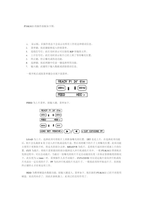
FT-R5055的操作面板如下图。
1.显示版:在操作状态下会显示出所有工作状态和错误信息。
2.菜单键:按此键能够进入控制菜单。
3.连线信号灯:此灯亮时表示可以接收RIP传输的文件。
4.上片信号灯:此灯亮时表示软片已经上到了等待曝光位置。
5.终止键:停止曝光或传送功能。
6.选择键:按此两键中任意一键选择所用功能。
7.输入键:此键用于输入数据或消除错误信息。
一般开机后或按菜单键会出现下面菜单。
FEED为上片菜单,按输入键,菜单如下。
LOAD为上片,选择此项可将软片上到准备曝光的位置。
SET也是上片,在选择此项功能后,软片会先裁掉8英寸送入冲片机或是收片盒,然后再将剩下的片子上到曝光位置。
此项功能主要用于更换软片时,将走光的部分去掉。
REMOVE为收片,是将软片退回到可重新上片的位置。
CUT为裁片,将软片需要裁切的部分裁掉送入冲片机或收片夹中。
一般FT-R5055照排机在发排过程中,可以自动裁片,当最后一张曝光的软片不足自动裁切长度(在保证套准精度的情况下,此长度为1.2mm)时,需要操作人员手动裁片。
CUT-COND可以设定裁片前向冲片机或收片夹送出一定长度的片子。
FF为向冲片机或收片夹送片子,一般按此项即开始送片子,直到按终止键停止才结束这项工作。
HDD为整理硬盘内数据功能,按输入键进入,菜单如下。
现在新的FT-R5055已经不再使用硬盘,而改用内存了,因此在新机器上,此项已经没有作用了。
OUT是将硬盘中接收到的还没有曝光的数据曝光。
CLR为清除硬盘中所有的数据。
使用选择键移至下边的菜单,见下图。
FILM为软片设定,按输入键进入后,见下面的菜单。
MF.1表示供片夹的编号,这个编号由贴于供片夹侧面的标识决定,不能够在菜单中修改。
在供片夹侧面粘贴标识时需要注意,要选择MF1-3,此为软片模式,软片会经过前后两个缓冲区,保证套准精度;选择MP1-3(相纸模式)、MD1-3(银盐版模式)时,材料不经过两个缓冲区,不能够保证套准精度。
水工混凝土掺用粉煤灰技术规范 条文说明

明水工混凝土掺用粉煤灰技术规范DL/T 5055-1996条文说明目次1.总则2.粉煤灰的技术要求3.粉煤灰在工程中的应用4.粉煤灰混凝土的质量检验1 总则1.0.1 多年来,水工混凝土掺用粉煤灰得到了比较广泛的应用,积累了大量科研成果和工程实际应用经验。
为了更正确、合理、广泛地应用粉煤灰,在总结水工混凝土掺用粉煤灰成熟经验的基础上,制订比较全面细致的水工混凝土粉煤炭应用技术规范是非常必要的,对进一步推动我国水工混凝土掺用粉煤灰、节约水泥、提高水工混凝土的质量,都有重要意义。
1.0.2 本规范是为水利水电主体工程及大型临建工程和其他重要附属建筑混凝土中掺用粉煤灰专门制订的。
由于水工混凝土量大面广,与其它建筑工程混凝土相比又有某些不同的特点,因此,本规范仅适用于水利水电工程现浇混凝土掺用粉煤炭。
1.0.3 本规范的编制,尽量与现行的国家和行业的有关规范相协调一致,但本规范是水工混凝土掺用粉煤灰针对性很强的技术规范,有自身的特点,与国家和行业有关规范的内容和要求不完全相同。
2 粉煤灰的技术要求2. 1 品质指标2.1.1 用于混凝土中的掺用粉煤灰按细度、烧失量、需水量比和三氧化硫四项指标数值,将掺用粉煤灰质量分为三个等级。
细度以45μm方孔筛筛余量表示,采用的理由是:①国内外试验资料表明,粉煤灰混凝土的强度与45μm筛余量控制粉煤灰细度的相关性,优于以8Oμm筛余量控制粉煤灰细度的相关性;②国外大多数国家都采用45μm筛余量表征粉煤灰的细度;③与新制订的粉煤灰质量国家标准和应用规范相一致。
烧失量大主要表现为含碳量多,对混凝土各种性能都有不利影响,因此,规定烧失量作为评定粉煤灰质量主要指标之一。
需水量比是评定粉煤灰质量的一项重要指标,需水量比反映了粉煤灰需水量的大小,粉煤灰需水量又与细度、含碳量有关,最终影响到混凝土的强度、施工和易性及耐久性。
国内外粉煤灰标准中都规定了对需水量比的要求。
粉煤灰中三氧化硫对粉煤灰混凝土早期强度有利。
WTN5系列语音芯片说明书
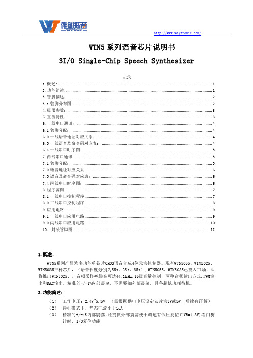
VDD=3V,Load=8 ohms
VDD=4.5V, Load=8 ohms
% VDD=4.5V, Load=8 ohms
△F/F Fosc
频偏 (VDD=3V) 振荡频率
-5 1.80
/
5
%
错误!
VDD=2.0~5.5V
(4) PWM纯音频输出,可直接驱动8Ω/0.5W喇叭和蜂鸣器,DAC音频输出,可外接功 放
(5) 内置看门狗; (6) 具备串口控制模式:一线串口,两线串口(最多可以加载255段语音, 后续有详
解) (7) 支持BUSY状态输出功能 选型注意: 1. 芯片的供电电压、控制方式和输出方式在烧写程序时已经设定好,不可以再次更改,订 做芯片时需要和业务员说明应用要求。 2. 使用串口控制方式时,最多可以加载 254 段语音,如要使用音量调节指令 EO~EFH 则相 应的减少 16 段语音。 芯片电压的设定决定了内部 LDO 的打开和关闭。注意芯片电压设定需和供电电压及电路 接线必须匹配,否则会导致芯片损坏或不工作。供电电压如下图:
Description 描述 电源负极 两线串口数据信号输入端 两线串口时钟信号输入端/一线串口数据信号输入端 Busy Low 信号 PWM 输出脚、DAC 输出脚 PWM 输出脚 电源正极,靠近芯片处建议连接 104 或 224 电容 烧写电源
/
2.功能简述:
(1) (2) (3)
工作电压:2.4V~5.5V;(需根据供电电压设定芯片为3V或5V,后续有详解) 待机模式下,静态电流小于1uA 精准的+/-1%内部震荡,还提供外部震荡便于调速有低压复位(LVR=1.8V)看门狗 计时、I/O复位功能
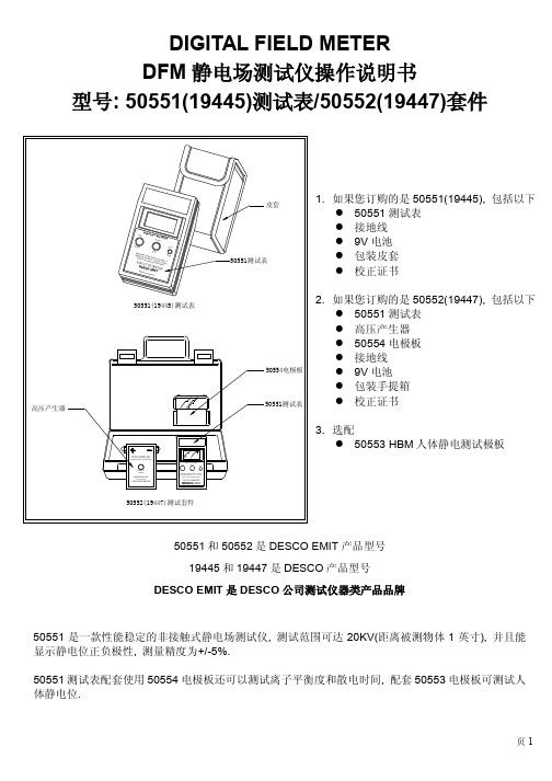
静电场测试仪操作说明书
DIGITAL FIELD METER DFM 静电场测试仪操作说明书型号: 50551(19445)测试表/50552(19447)套件50551和50552是DESCO EMIT 产品型号 19445和19447是DESCO 产品型号DESCO EMIT 是DESCO 公司测试仪器类产品品牌50551是一款性能稳定的非接触式静电场测试仪, 测试范围可达20KV(距离被测物体1英寸), 并且能显示静电位正负极性, 测量精度为+/-5%.50551测试表配套使用50554电极板还可以测试离子平衡度和散电时间, 配套50553电极板可测试人 体静电位.页11. 如果您订购的是50551(19445), 包括以下l 50551测试表 l 接地线 l 9V 电池 l 包装皮套 l 校正证书2. 如果您订购的是50552(19447), 包括以下l 50551测试表 l 高压产生器 l 50554电极板 l 接地线 l 9V 电池 l 包装手提箱 l 校正证书3. 选配l 50553 HBM 人体静电测试极板一. 产品使用1. 开机l 按一下”ON/ZERO ”键开机2. 调零l 50551测试表在第一次使用时需调零, 以后再次使用时不需调零直到更换电池.l 操作人员通过手腕带或防静电鞋接地, 也可采用配套接地线把仪器直接接地. 将50551测试表对准一个接地的导体(通常可选择一面墙), 按住”ON/ZERO ”键, 当屏幕显示”0.00”后松开按键, 调零完成. l 仪器调零时和接地导体之间的距离没有关系, 可在任意距离调零.3. 测试物体表面静电位l 将50551测试表对准被测物体, 距离1英寸(2.54cm). 50551前部有2个LED 灯产生红色光线形成2个光环, 变化测试表和物体间的距离, 当2个光环重叠为1个光环时表示距离为1英寸.l 当物体表面静电为负值时, 屏幕显示的数值前有”-“符号; 当物体表面静电为正值时, 屏幕显示的数值前没有符号l 按一下”HOLD/OFF ”键, 可保持屏幕当前读数, 再按一下”HOLD/OFF ”键解除该功能 l 50551表的测量单位为KV4. 关机按住”HOLD/OFF ”键3秒后仪器关机接地线插孔开机/调零按键保持读数/关注意!当屏幕显示”STOP!”时, 说明物体表面静电位超过20KV, 需增加测试距离, 具体如下: A. 距离被测物体4英寸(10.16cm), 测量范围可到40KV, 屏幕读数需乘2 ( x 2) B. 距离被测物体6.5英寸(16.51cm), 测量范围可到60KV, 屏幕读数需乘3 ( x 3) C. 距离被测物体8.5英寸(21.59cm), 测量范围可到80KV, 屏幕读数需乘4 ( x 4) 相关操作注意事项1. 仪器外壳为导电塑料, 因此在人员配戴手腕带或静电消散工作鞋时, 可不使用配套接地线将仪器直接接地2. 在测试中, 不要按”ON/ZERO ”键, 否则仪器进入调零状态, 屏幕显示的数值不是被测物体实际静电位3. 测试精确度和仪器是否正确接地, 测试距离是否1英寸, 被测物体面积等因素有关. 被测物体表面应该是测试距离的3倍以上. 例如1英寸测试距离, 则被测物体表面至少在3平方英寸以上 页2二. 配套使用50554电极板测试离子平衡度和散电时间50551测试表可配套50554电极板以评估静电消除器的性能--测试离子平衡度和消除静电时间将配套50554电极板从50551的前部顺着两边的滑槽插入开机后按住调零键, 同时用手指连接50554极板和50551测试表导电外壳以调零1. 测试离子平衡度将测试表对准静电消除器, 距离12英寸(30.48cm), 屏幕显示的读数是静电消除器产生的正负离子差额(离子平衡度), 该值越小越好, 离子平衡度为静电消除器可将物体静电位降到最低的数值.2. 测试散电时间配套高压产生器可产生+/-1100V 电压,通过左右2个电极输出A. 测试正散电时间测试人员正确接地, 按住高压产生器中间的按键, 同时手指接触右边的负高压输出点, 将左边的正高压输出点接触50554极板, 这时50551测试表屏幕会显示”+1.10kV ”, 然后把50551测试表对准静电消除器, 距离12英寸, 用秒表记录从+1.10kV 降到+0.01kV 所需时间.B. 测试负散电时间测试人员正确接地, 按住高压产生器中间的按键, 同时手指接触左边的正高压输出点, 将右边的负高压输出点接触50554极板, 这时50551测试表屏幕会显示”-1.10kV ”, 然后把50551测试表对准静电消除器, 距离12英寸, 用秒表记录从-1.10kV 降到-0.01kV 所需时间.页3电极板正高压输出点高压产生器测试负散电时间示意图配套使用50553HBM 极板测试人体静电位l 首先把50554电极板固定在50551测试表上, 然后再插在50553极板上, 用50553极板上的螺钉固定 l 把配套接地线插入50551测试表的接地孔, 另一端接地l 测试人员手握50553极板, 这时测试表屏幕读数为人体静电位. 走动或挥动手臂检测是否摩擦起电 l 测试人员手握50553极板坐在防静电椅子上, 前后移动, 检测是否摩擦起电三. 产品保修产品保修期1年, 由于人为损害不在保修范围.测试表页4中文说明仅供参考, 请以英文说明书为准Copyright © APCEE Corporation。
CCAA考试指南-QMS简答题汇编
CCAA考试指南QMS简答题汇编说明:习题来自网上收集,包括2007年6月份QMS考试的简答题。
欢迎大家到CCAA考试论坛参与讨论。
有关于CCAA考试的最新信息、资料,古笼都会在第一时间发布到认证之友()、CCAA考试论坛(/),请大家关注这两个网站。
欢迎大家转载「古笼」提供的习题集及参考答案,请注明来自「认证之友」。
大家有任何问题请直接与「古笼」联系,QQ:503255124;Email:sc126tbs@5001仓库前,审核员看见几个搬运工在仓库保管员的指挥下正在挑选一批DH21型密封件,审核员问仓库保管员他们在干什么?仓库保管员说:“这是一批星河公司退回的不合格的密封件,只是表面上有些毛刺,外观有点小问题,我们将其中外观较好的挑出入库,外面实在不好的再退回车间进行打磨处理,这样可以减少损失”。
作为审核员,应该如何进一步追踪审核(至少写出三个步骤)5002简述质量管理原则中的“过程方法”原则和“管理的系统方法”原则。
5003简述文件的作用和具体用途。
5004请列举五条认证人员从事认证活动禁止有的行为。
5005某企业没有产品的设计和开发能力,产品的设计委托给另一专业机构,但该企业参与设计评审和设计确认,该组织是否可以删减9001-2000标准中“7.3设计和开发”过程?为什么?5006简要说明9001标准中“5.2以顾客为关注焦点”、“7.2.1与产品有关的要求的确定”和“8.2.1顾客满意”之间的关系。
5007GB/T19001-2000标准中那些条款要求保持记录,至少举出五个条款。
50089001标准中5.3、5.5.1、5.6分别体现了哪些质量管理原则?为什么?5009常规控制图要求总体特性值服从的分布,试举出三个例子加以说明。
5010如何理解9001标准中4.2.1中“组织为确保其过程的有效策划、运行和控制所需的文件”的要求?5011请阐明审核组进入现场后,首次会议以前所召开的准备会的主要目的。
VAS5054A_VAS5055_mit_VAS5052A_VAS6150_CHN_V1_11

安装和调试
保留所有权利。
页码7
将 VAS 5054A、VAS 5055 安装到 VAS 5052A(自基础 CD 16 起)/VAS 6150(基础 CD 15)上 V1.11
VAS 5054A / VAS 5055 操作手册
1.5
更改蓝牙密码
在 VAS 5054A 的出厂状态下,蓝牙密码预编程为设备的 9 位数系列号。 更改预设的蓝牙密码 将您的 VAS 5054A 通过 USB 连接至 VAS 5052A/VAS 6150。通过双击 Windows 桌面上的相应 图标,启动配置程序 Diagnostic Interface Configuration Utility(诊断接口配置工具)。如要 了解如何通过蓝牙使用该程序,请阅读章节1.10。 在蓝牙参数区域中,按照大众的规定向密码栏位中输入一个新的密码:它必须至少为 6 位,且由 字母和数字构成。也可以使用特殊字符。 确保安全模式被设定为 4(参见图 1-5)。 按 OK(确定)接受更改。在通过蓝牙安装 VAS 5054A 时,Windows 蓝牙软件稍后将要求您输 入新的密码 - 该处被称为主密钥。
提示
安装按以下顺序进行: 1. 2. 3. 4. 5. 6. 7. 8. 9. 安装 VAS 软件 将 VAS 5054A 连接至车辆 调整蓝牙安全设置 通过 USB 连接并安装 VAS 5054A 更改 VAS 5054A 的蓝牙密码 建立与 VAS 5054A 的连接 安装 VAS 5054A 用于蓝牙应用 检查 EDIC 软件配置中的设置 可选项:将修理厂测试仪或诊断笔记本电脑由 VAS 5055 转为 VAS 5054A 运行模式
图1-1 Windows XP Service Pack 2 及以上版本的蓝
金立 无线电按键盘 PN 050550说明书
M a d e i n Italy
Part # 050550
Thank you for choosing this product. Please read this manual carefully before using the product.
1 - Introduction
The Wireless Keypad ( PN 050550 ) is an encoded radio keypad operating at 433,92 MHz.The best use of the product is on applications where an encrypted radio signal has to be used to control: gates, garage doors, rolling shutters, sun-blinds, anti-burglar appliances, lightings, etc. The code has a very high security coding system (19683 code combinations). The radio transmission is enabled only after the dialing of a security user code. There are up to 4+2 different channels that can activate up to 6 different receivers or relays. The internal memory can store up to 24 different access codes and 1 Master code. The product fully complies with the European directives 89/336/CEE, 99/05/CE and Part. 15 of FCC Rules..
05履带起重机安全规程
《履带起重机安全规程》(JG/T 5055-1994)资料介绍中华人民共和国建筑工业行业标准JG5055一94履带起重机安全规程Safety rules for crawler crane中华人民共和国建设部1994-12-02批准1995-07-01实施1 主题内容与适用范围本标准规定了最大额定总起重量为150t以下(含150t,下同)的履带起重机(以下简称起重机)轰造、使用、维修以及设计方面的安全要求。
本标准适用于最大额定总起重量150t以下的机械式、液压式、电动式析架臂起重机,对最大额定总起重量大于150t的起重机和伸缩臂起重机可参照使用。
2 引用标准GB 3811 起重机设计规范GB 5972 起重机械用钢丝绳检验和报废实用规范GB 6067 起重机械安全规程GB 6946 钢丝绳铝合金压制接头GB/T 14560 150t以下履带起重机技术条件GB/T 13306 标牌JJ 12.1 建筑机械焊接质量规定JB 2299 矿山、工程起重运输机械产品涂漆颜色和安全标志3 起重特性和抗倾翻稳定性3.1 起重机应有额定起重性能表,性能参数及起升高度曲线标牌。
它必须固定在能使操作者便于看到的操纵室内。
标牌尺寸应符合GB/T13306的规定。
3.2 起重机整机静稳定性验算,应符合GB/T14560的规定。
3.3 起重机后翻稳定性要求:起重机停放在坚实而水平的支承面上,装有基本臂、最长主臂或主臂加副臂组合,处于最小幅度的位置,吊钩放置地面,工作风压从臂架吹向平衡重,在最不稳定的方向上,起重机的重心至回转轴线之间的距离不得超过从回转轴线至后倾翻线之间距离的70%。
起重机倾翻线见图la表示的支重轮下部倾翻支点连线A--A和图1b表示的左、右履带的导向轮或驱动轮倾翻点的连线B-B。
4 金属结构4.1 材料起重机所用的主要材料应符合GB 3811和GB/T1456。
的规定,对所用原材料应进行检验,不符合规定的不得使用。
Philips 49BDL5055P 强壮的专业全高清显示器说明书
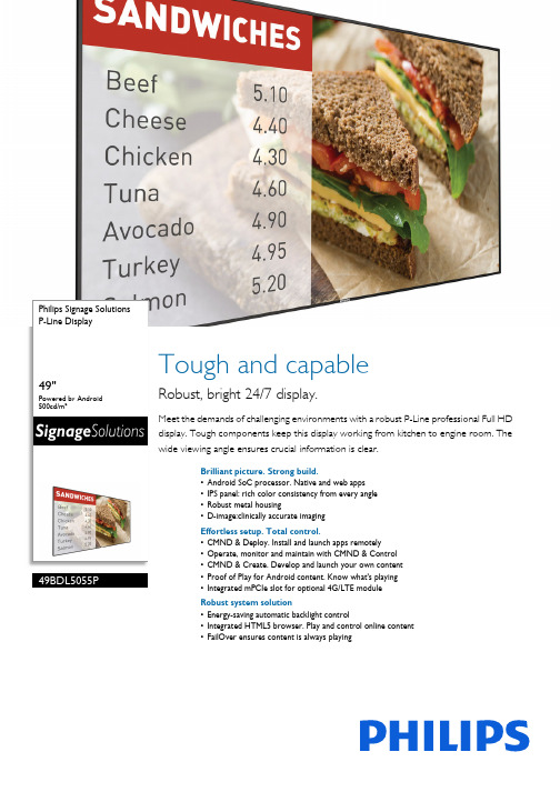
Philips Signage Solutions P-Line Display49"Powered by Android 500cd/m²49BDL5055PTough and capableRobust, bright 24/7 display.Meet the demands of challenging environments with a robust P-Line professional Full HD display. Tough components keep this display working from kitchen to engine room. The wide viewing angle ensures crucial information is clear.Brilliant picture. Strong build.•Android SoC processor. Native and web apps •IPS panel: rich color consistency from every angle •Robust metal housing•D-image:clinically accurate imagingEffortless setup. Total control.•CMND & Deploy. Install and launch apps remotely •Operate, monitor and maintain with CMND & Control •CMND & Create. Develop and launch your own content •Proof of Play for Android content. Know what's playing •Integrated mPCIe slot for optional 4G/LTE module Robust system solution•Energy-saving automatic backlight control•Integrated HTML5 browser. Play and control online content •FailOver ensures content is always playingHighlightsPowered by AndroidControl your display via an Internet connection. Android-powered PhilipsProfessional Displays are optimized for native Android apps, and you can install web apps directly to the display too. A new Android OS ensures the software is kept secure and remain to the latest specification for longer.D-imageThis Philips Professional Display is factory-calibrated to meet clinical compliance standards for greyscale performance. The optimal image achieved by the display can be used to review medical images in consultation rooms or lecture theatres.CMND & ControlRun your display network over a local (LAN) connection. CMND & Control allows you to perform vital functions like controlling inputsand monitoring display status. Whether you're in charge of one screen or 100.CMND & Create Take control of your content with CMND & Create. A drag-and-drop interface makes it simple to publish your own content-whether it's a daily specials board or branded corporate information. Preloaded templates andintegrated widgets ensure your stills, text, and video will be up and running in no time.CMND & DeployQuickly install and launch any app-even when you're off-site and working remotely. CMND & Deploy lets you add and update your own apps, as well as apps from the PhilipsProfessional Display App Store. Simply scan the QR code, log in to the store, and click on the app you want to install. The app is automatically downloaded and launched.Integrated mPCIe slotEasily connect 4G/LTE modules to your Philips professional display. The integrated mPCIe slot enables your display to communicate with other devices that share the same wirelessconnectivity. Invaluable if you're installing displays in locations such as banks orgovernment buildings, where you cannot get onto the local network.FailOverFrom waiting room to meeting room, never show a blank screen. FailOver lets your Philips Professional Display switch automatically between primary and secondary inputs ensuring content keeps playing even if the primary source goes down. Simply set a list of alternate inputs to be sure your business is always on.OPS slotIntegrate a full-power PC or Android-powered CRD50 module directly into your Philips Professional Display. The OPS slot contains all the connections you need to run your slot-in solution, including a power supply.Issue date 2022-07-14Version: 11.1.112 NC: 8670 001 41453EAN: 87 12581 74218 8© 2022 Koninklijke Philips N.V.All Rights reserved.Specifications are subject to change without notice. Trademarks are the property of Koninklijke Philips N.V. or their respective owners.SpecificationsPicture/Display•Diagonal screen size: 48.5 inch / 123.2 cm •Panel resolution: 1920x1080p•Optimum resolution: 1920 x 1080 @ 60Hz •Brightness: 500 cd/m²•Contrast ratio (typical): 1300:1•Dynamic contrast ratio: 500,000:1•Aspect ratio: 16:9•Response time (typical): 8 ms•Pixel pitch: 0.55926 x 0.55926 mm •Display colors: 1.07 billion•Viewing angle (H / V): 178 / 178 degree •Operating system: Android 5.1.1Connectivity•Video input: Display Port1.2 (x1), DVI-I (x 1), HDMI 1.4 (x2), USB 2.0 (x2), USB 2.0 (x1)•Video output: DisplayPort (x1), DVI-I (x1)•Audio input: 3.5 mm jack •Audio output: 3.5mm jack•Other connections: OPS, Micro SD (x1), Micro USB(type B)x1•Optional WiFi functionality: requires WiFi module and external antennas•External control: RJ45, RS232C (in/out) 2.5 mm jack, IR (in/out) 3.5 mm jackSupported Display Resolution•Computer formats Resolution Refresh rate 1024 x 768 60, 75Hz 1280 x 1024 60Hz 1280 x 768 60Hz 1280 x 800 60Hz 1360 x 768 60Hz 1600 x 1200 60Hz 1920 x 1080 60Hz 640 x 480 60, 72, 75Hz 720 x 400 70Hz 800 x 600 60, 75Hz •Video formats Resolution Refresh rate 1080i 25, 30Hz 1080p 50, 60Hz 480I 30Hz 480p 60Hz 576i 25Hz 576p 50Hz 720p 50, 60HzDimensions•Set dimensions (W x H x D):1092.8 x 623.0 x 56.8 mm•Set dimensions in inch (W x H x D): 43.0 x 24.5 x 2.3 inch •Bezel width: 6.5 mm•Product weight (lb): 41.9 lb •Product weight: 19.0 kg•Wall Mount: 400 x 400 mm, M6Convenience•Placement: Landscape, Portrait •Tiled Matrix: Up to 15 x 15•Keyboard control: Hidden, Lockable•Signal loop through: IR Loopthrough, DisplayPort, DVI, RS232, VGA•Network controllable: RJ45, HDMI (One Wire), RS232•Energy saving functions: Smart Power•Screen saving functions: Pixel Shift, Low Bright •Ease of installation: AC Out, Smart Insert, Carrying Handles•Other convenience: G sensorPower•Standby power consumption: <0.5 W •Mains power: 100 ~ 240 VAC, 50 ~ 60 Hz •Consumption (Typical): 95 W •Consumption (EPA 7.0): 82.08 W •Energy Label Class: GOperating conditions•Temperature range (operation): 0 ~ 40 °C•Temperature range (storage): -20 ~ 60 °C •Relative humidity: 20 ~ 80(operation),5 - 95(storage) %•Altitude: 0 ~ 3000 m •MTBF: 60,000 hour(s)Sound•Built-in speakers: 2 x 10W RMSAccessories•Included accessories: Batteries for remote control, Quick start guide, Remote Control, AC Power Cord, RS232 cable•Included Accessories: Edge Alignment Kit (2)-1pcs, Philips logo (x1), Thumbscrew (8pcs), EdgeAlignment Kit (1 )-2pcs, RS232 daisy-chain cable, Wifi Antennas (2 pcs)•Stand: BM04642/00(Optional)Multimedia Applications•USB Playback Audio: AAC, M4A, MP1, MP2, MP3,WMA•USB Playback Picture: BMP, GIF, JPEG, JPG, PNG •USB Playback Video: 3GP, AVI, DAT, FLV, MKV, MOV, MP4, MPG, TS, VOB, WEBMMiscellaneous•On-Screen Display Languages: English, French, German, Spanish, Polish, Turkish, Russian, Italian, Simplified Chinese, Traditional Chinese, Arabic, Japanese, Danish, Dutch, Finnish, Norwegian, Portuguese, Swedish•Regulatory approvals: EnergyStar 7.0, CE, FCC, Class B, CCC, BSMI, CB, VCCI, CECP, EAC, PSB, EMF, UL/cUL•Warranty: 3 year warrantyInternal Player•CPU: Octacore Cortex A53 1.5GHz •GPU: PowerVR SGX6110•Memory: 2GB DDR3•Storage: 16GB EMMC。
戴尔 OptiPlex 5055 小型机快速入门指南说明书

1Connect the keyboard and mouseConecte el teclado y el mouse2Connect the network cable — optionalConecte el cable de red (opcional)3Connect the displayConecte la pantallaIf you ordered your computer with a discrete graphics card, connect the display to thediscrete graphics card.si usted solicitó el equipo con una tarjeta de gráficos discretos, conecte la pantalla a la tarjeta de gráficos discretos.4Connect the power cable and press the power buttonConecte el cable de alimentación y presione el botón de encendido5Finish operating system setupFinalice la configuración del sistema operativoWindows 10Connect to your networkConectarla a la redIf you are connecting to a secured wireless network, enter the password for the wireless network access when prompted.Si va a conectar a una red inalámbrica segura, introduzca la contraseña para acceder a la red inalámbrica cuando se le solicite.Sign in to your Microsoft account or create a local accountInicie sesión en su cuenta de Microsoft o cree una cuenta local.UbuntuFollow the instructions on the screen to finish setup.Siga las instrucciones en pantalla para finalizar la configuración.Locate Dell appsBusque aplicaciones DellSupportAssistCheck and update your computer Compruebe y actualice la computadoraFeaturesFunciones1. Optical drive (optional)2. USB 2.0 port with PowerShare3. Power button and power light4. Line-out port5. Hard drive activity light6. Memory card reader (optional)7. Headset port8. Serial port9. USB 2.0 port 10. PS/2 keyboard port 11. USB 3.1 Gen1 ports12. USB 2.0 ports (supportsSmart Power On)13. Expansion card slots 14. Power connector port 15. Power supply diagnostic light 16. Cable cover lock slot 17. Release latch 18. PS/2 mouse port 19. Network port20. Kensington security cable slot 21. Padlock ring1. Unidad óptica (opcional)2. Puerto USB 2.0 con PowerShare3. Botón de encendido e indicadorluminoso de alimentación 4. Puerto de línea de salida5. Indicador luminoso de actividad de launidad de disco duro 6. Lector de tarjeta de memoria(opcional) 7. Puerto para auriculares 8. Puerto serie 9. Puerto USB 2.010. Puerto para teclado PS/211. Puertos USB 3.1 de primerageneración12. Puertos USB 2.0 (admiteencendido inteligente)13. Ranuras para tarjetas de expansión 14. Puerto del conector de alimentación 15. Indicador luminoso de diagnósticodel suministro de energía 16. Ranura de bloqueo de la cubierta delcable 17. Seguro de liberación 18. Puerto para mouse PS/219. Puerto de red20. Ranura para cable de seguridadKensington 21. Anillo del candadoProduct support and manuals Manuales y soporte del producto/support/support/manuals /support/windowsContact DellComuníquese con Dell/contactdellRegulatory and safetyInformación reglamentaria y de seguridad /regulatory_compliance Regulatory model Modelo reglamentario D11S Regulatory type Tipo reglamentario D11S003Computer modelModelo de computadoraOptiPlex 5055 SFFInformación para NOM, o Norma Oficial MexicanaLa información que se proporciona a continuación se mostrará en los dispositivos que se describen en este documento, en conformidad con los requisitos de la Norma Oficial Mexicana (NOM):Importador:Dell México S.A. de C.V.Paseo de la Reforma 2620 - Piso 11.° Col. Lomas Altas11950 Ciudad de México.Número de modelo reglamentario:D11S Voltaje de entrada:100 V AC–240 V AC Corriente de entrada (máxima):4,0 A Frecuencia de entrada:50 Hz–60 Hz2017-08© 2017 Dell Inc. or its subsidiaries.© 2017 Microsoft Corporation.© 2017 Canonical Ltd.。
Philips 49BDL5055P P-Line Display 说明书
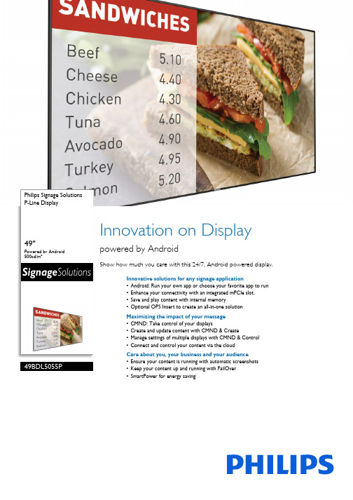
Philips Signage Solutions P-Line Display49"Powered by Android 500cd/m²49BDL5055PInnovation on Displaypowered by AndroidShow how much you care with this 24/7, Android powered display.Innovative solutions for any signage application•Android: Run your own app or choose your favorite app to run •Enhance your connectivity with an integrated mPCIe slot.•Save and play content with internal memory•Optional OPS Insert to create an all-in-one solution Maximizing the impact of your message •CMND: Take control of your displays•Create and update content with CMND & Create•Manage settings of multiple displays with CMND & Control •Connect and control your content via the cloudCare about you, your business and your audience •Ensure your content is running with automatic screenshots •Keep your content up and running with FailOver •SmartPower for energy savingHighlightsPowered by AndroidWIth Android OS integrated into the display, you can work with the most developed OS on the planet and save your own app directly into the display. Or, choose from the large library of Android apps and play content from there. With the built-in scheduler, you can daypart your apps and content based on yourcustomer and time of day and with the auto orientation feature, showing content inportrait or landscape is as simple as turning the display.PCI SlotWith an integrated PCI slot, you can connect a WiFI/bluetooth or 4G LTE module, allowing for even greater communication with the display. Machine to machine communication is also enhanced, with numerous configurations available for customers to use, such as the ability to expand product features or signal-handling capability.Proof of PlayContent is king, and with the automaticscreenshot feauture, you can make sure that your content is up and running at all times. Screenshots are taken throughout the day, which are then stored in the FTP server. From there, the screenshots can be viewed no matter when, or where you are.Internal MemorySave and play content with internal memory. Upload your media into the display and playback content immediately. Working in conjunction with the internal browser, it also serves as a memory cache when streaming online content. If the network ever fails, the internal memory keeps content running by playing a cached version of the content,ensuring that your media stays up even if the network goes down.FailOver Keeping your content up and running is critical for demanding commercial applications. While it is unlikely you will face a content disaster, FailOver provides content protection with a revolutionary technology that plays back-up content on screen in the event of a media player failure. FailOver automatically kicks in when the primary input fails. Simply select a primary input connection and a FailOver connection and your ready for instant protection.CMNDA robust display management platform,CMND puts the power back into your hands. Update and manage content with CMND & Create or control your settings with CMND & Control. It's all possible with CMND.CMND & ControlWith CMND & Control, easily managemultiple displays in a central location. With real time display monitoring, setting and software updates from a remote location, and the ability to customize and configure multiple displays at once, such as video wall or menu boarddisplays, controlling your suite of displays has never been easier.CMND & CreateDesign and create compelling content with CMND & Create, a powerful authoring tool. With a drag and drop interface, preloaded templates, and integrated widgets, you'll be able to amaze your customers with compelling content. Available in portrait and landscape mode.OPS InsertTurn your display into an all-in-one digital signage solution and create a display network which is connected, intelligent and secure. Open Pluggable Specification (OPS) is anindustry standard slot into which you can add an OPS-standardized media player. This cable free solution gives you the ability to install, use or maintain your hardware whenever you need.SmartBrowserConnect and control your content via the cloud with the integrated HTML5 browser. Using the Chromium based browser, design your content online and connect a single display, or your complete network. Show content in both landscape and portrait mode, with fullHD resolution. Streaming content can also be shown in a PIP (picture-in-picture) window. Simply connect the display to the internet using WiFi or with an RJ45 cable, and enjoy your own created playlistsIssue date 2022-07-14 Version: 5.0.112 NC: 8670 001 48616 EAN: 69 51613 91321 5© 2022 Koninklijke Philips N.V.All Rights reserved.Specifications are subject to change without notice. Trademarks are the property of Koninklijke Philips N.V. or their respective owners.SpecificationsPicture/Display•Diagonal screen size: 48.5 inch / 123.2 cm •Panel resolution: 1920x1080p•Optimum resolution: 1920 x 1080 @ 60Hz •Brightness: 500 cd/m²•Dynamic contrast ratio: 500,000:1•Aspect ratio: 16:9•Pixel pitch: 0.55926 x 0.55926 mm•Display colors: 1.07 billion•Viewing angle (H / V): 178 / 178 degree •Operating system: Android 5.1.1 Connectivity•Video input: Display Port1.2 (x1), DVI-I (x 1), HDMI 1.4 (x2), USB 2.0 (x2), USB 2.0 (x1)•Video output: DisplayPort (x1), DVI-I (x1)•Audio input: 3.5 mm jack•Audio output: 3.5mm jack•Other connections: OPS, Micro SD (x1), Micro USB(type B)x1•Optional WiFi functionality: requires WiFi module and external antennas•External control: RJ45, RS232C (in/out) 2.5 mm jack, IR (in/out) 3.5 mm jackSupported Display Resolution •Computer formatsResolution Refresh rate1920 x 1080 60Hz1360 x 768 60Hz1280 x 800 60Hz1280 x 768 60Hz1024 x 768 60, 75Hz1280 x 1024 60Hz1600 x 1200 60Hz640 x 480 60, 72, 75Hz720 x 400 70Hz800 x 600 60, 75Hz•Video formatsResolution Refresh rate1080p 50, 60Hz720p 50, 60Hz576p 50Hz480p 60Hz1080i 25, 30Hz480I 30Hz576i 25HzDimensions•Set dimensions (W x H x D):1092.78 x 623.0 x 56.8 mm•Bezel width: 6.5 mm•Product weight: 19.0 kg•Wall Mount: 400 x 400 mm, M6 Convenience•Placement: Landscape, Portrait•Tiled Matrix: Up to 15 x 15•Keyboard control: Hidden, Lockable •Signal loop through: DVI, VGA, RS232, IR Loopthrough, DisplayPort•Network controllable: RJ45, RS232, HDMI (One Wire)•Energy saving functions: Smart Power •Screen saving functions: Pixel Shift, Low Bright •Ease of installation: AC Out, Smart Insert, Carrying Handles•Other convenience: G sensorPower•Standby power consumption: <0.5 W•Mains power: 100 ~ 240 VAC, 50 ~ 60 Hz •Consumption (Typical): 95 W •Consumption (EPA 7.0): 82.08 WOperating conditions•Temperature range (operation): 0 ~ 40 °C •Temperature range (storage): -20 ~ 60 °C •Relative humidity: 20 ~ 80 %•Altitude: 0 ~ 3000 m•MTBF: 60,000 hour(s)Sound•Built-in speakers: 2 x 10W RMS Accessories•Included accessories: Remote Control, Batteries for remote control, Quick start guide, AC Power Cord, RS232 cable•Included Accessories: Edge Alignment Kit (1 )-2pcs, Edge Alignment Kit (2)-1pcs, Philips logo (x1), Thumbscrew (8pcs), RS232 daisy-chain cable, Wifi Antennas (2 pcs)•Stand: BM04642/00(Optional)Multimedia Applications•USB Playback Audio: AAC, M4A, MP3, WMA, MP1, MP2•USB Playback Picture: BMP, GIF, JPEG, JPG, PNG •USB Playback Video: MKV, MP4, MPG, TS, VOB, 3GP, AVI, DAT, FLV, MOV, WEBM Miscellaneous•On-Screen Display Languages: English, French, German, Spanish, Polish, Turkish, Russian, Italian, Simplified Chinese, Traditional Chinese, Arabic, Japanese, Danish, Dutch, Finnish, Norwegian, Portuguese, Swedish•Regulatory approvals: EnergyStar 7.0, CE, FCC, Class B, CCC, BSMI, CB, VCCI, CECP, EAC, PSB, EMF•Warranty: 3 year warrantyInternal Player•CPU: Octacore Cortex A53 1.5GHz•GPU: PowerVR SGX6110•Memory: 2GB DDR3•Storage: 16GB EMMC。
- 1、下载文档前请自行甄别文档内容的完整性,平台不提供额外的编辑、内容补充、找答案等附加服务。
- 2、"仅部分预览"的文档,不可在线预览部分如存在完整性等问题,可反馈申请退款(可完整预览的文档不适用该条件!)。
- 3、如文档侵犯您的权益,请联系客服反馈,我们会尽快为您处理(人工客服工作时间:9:00-18:30)。
FT-R5055的操作面板如下图。
1.显示版:在操作状态下会显示出所有工作状态和错误信息。
2.菜单键:按此键能够进入控制菜单。
3.连线信号灯:此灯亮时表示可以接收RIP传输的文件。
4.上片信号灯:此灯亮时表示软片已经上到了等待曝光位置。
5.终止键:停止曝光或传送功能。
6.选择键:按此两键中任意一键选择所用功能。
7.输入键:此键用于输入数据或消除错误信息。
一般开机后或按菜单键会出现下面菜单。
FEED为上片菜单,按输入键,菜单如下。
LOAD为上片,选择此项可将软片上到准备曝光的位置。
SET也是上片,在选择此项功能后,软片会先裁掉8英寸送入冲片机或是收片盒,然后再将剩下的片子上到曝光位置。
此项功能主要用于更换软片时,将走光的部分去掉。
REMOVE为收片,是将软片退回到可重新上片的位置。
CUT为裁片,将软片需要裁切的部分裁掉送入冲片机或收片夹中。
一般FT-R5055照排机在发排过程中,可以自动裁片,当最后一张曝光的软片不足自动裁切长度(在保证套准精度的情况下,此长度为1.2mm)时,需要操作人员手动裁片。
CUT-COND可以设定裁片前向冲片机或收片夹送出一定长度的片子。
FF为向冲片机或收片夹送片子,一般按此项即开始送片子,直到按终止键停止才结束这项工作。
HDD为整理硬盘内数据功能,按输入键进入,菜单如下。
现在新的FT-R5055已经不再使用硬盘,而改用内存了,因此在新机器上,此项已经没有作用了。
OUT是将硬盘中接收到的还没有曝光的数据曝光。
CLR为清除硬盘中所有的数据。
使用选择键移至下边的菜单,见下图。
FILM为软片设定,按输入键进入后,见下面的菜单。
MF.1表示供片夹的编号,这个编号由贴于供片夹侧面的标识决定,不能够在菜单中修改。
在供片夹侧面粘贴标识时需要注意,要选择MF1-3,此为软片模式,软片会经过前后两个缓冲区,保证套准精度;选择MP1-3(相纸模式)、MD1-3(银盐版模式)时,材料不经过两个缓冲区,不能够保证套准精度。
F1为软片的参数种类,可以将不同软片的光值存在不同的参数种类中,更换软片时,只要改变参数种类即可调出其中的光值使用,不需重新调整光值。
每个供片夹编号中只能存储三组参数。
在参数种类后面的数值表示所用软片的宽度,这一数值需要用户根据实际所上软片的宽度进行修改,机器不能自动检测。
60M表示现在所剩软片的长度,在每次更换软片后,这一长度也需要用户自己修改。
SPC表示所出文件间的间隙,按输入键出现下面的菜单。
AUTOSPACE是指两个文件之间的空隙有多少,用户可以自行修改,但数值范围为10-99mm,不可以设为0,即为省片子,两文件间没有空隙是不行的。
CUT-L为裁切线,按输入键可出现下面的菜单。
裁切线一项打开后,在输出的两个文件间会出现一条黑线,这是为了便于用户裁切片子,但一般这项不用打开。
将OFF改为ON打开此项后出现的菜单中,SPC表示裁切线到文件边缘的距离,数值调整范围为1-99mm,WIDTH表示裁切线的宽度,可以设为0.1-3.0mm。
这样,每个文件的曝光长度为:页面尺寸(包括页面信息)+页面间设定空间+裁切线空间+裁切线宽度。
使用选择键移至下边的菜单,见下图。
LASER表示激光值。
在FT-R5055照排机的使用中,激光值的测定和调整是十分重要的。
按输入键可出现下面的菜单。
以1200dpi精度为例,LASER(12,100)表示精度为1200dpi时的光值为100,需要修改精度,只需将光标移至12处,使用选择键更改即可,光值的修改也是如此。
选择好合适的光值后,将光标移至EXP处,曝光出软片测试条,然后使用密度计测量。
曝光出的软片测试条见下图。
曝光后一共会出七组曝光测试条(图中只显示出五组),中间一组即从上边数第四组(图中从上数第三组)为当前光值下的曝光测试条,从这组依次往上为当前的光值-5、-10、-15的曝光测试条,从这组依次往下为当前的光值+5、+10、+15的曝光测试条。
每组曝光测试条包括实地(100%)的情况、50%的情况等。
在软片最下方的线条表示软片所出的精度,一条线代表1000dpi,两条线代表1200dpi,三条线代表1500dpi,四条线代表1800dpi,五条线代表2400dpi,六条线代表3000dpi。
测试条的用法是,先测量实地密度,一般胶印要求实地密度4.0以上,报纸印刷要求实地密度3.4以上。
如果几组测试条中的实地密度都达不到要求,就需要修改光值重新曝光出测试条。
如果有一组能够达到要求,则选择这组光值输入即可。
如果有几组均达到要求,需要测量50%地方的网点百分比,选择最接近50%的那组光值输入即可。
如:1200dpi时,光值设定为100出测试条,测量出从上往下数第六条满足条件,则1200dpi时应该使用光值为110,将1200dpi的光值调整为110即可。
在调整光值时应该注意几点:一是做光值调整前,应该将冲片机的状态稳定,如调整好显影时间、温度等;二是不同精度的光值不一定一样,每种精度的光值要分别调整;三是不同品牌的软片光值不同,在更换软片时要进行调整;四是光值的范围为
40-300,当大于300时,照排机可能镜头需要擦拭,也可能激光头有故障需要更换,建议联系专业的维修人员。
VERSION为查询控制版的版本,按输入键可出现下面的菜单。
I/F指SCSI控制版的版本号,MCON指主控制版的版本号,DA T指本机的操作参数。
版本号只能查看不能修改。
使用选择键移至下边的菜单,见下图。
SCSI-ID是指本机的SCSI号,按输入键可出现下面的菜单。
网屏照排机出厂时的SCSI ID号均为6,如果与其它外设没有冲突,建议不要更改。
需要修改时,只需将数值改为想要的数值即可。
最后一项BUZZER为控制声音,当它处于ON的状态时,按动控制面板上的按钮,机器会发出“Beeps”的声音。
