H2氢气浓度传感器
氢气H2检测仪报警器探测器探头
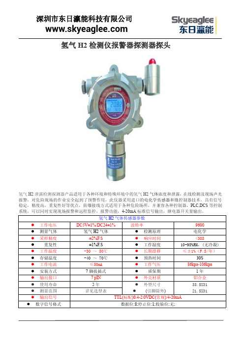
氢气H2检测仪报警器探测器探头氢气H2泄露检测探测器产品适用于各种环境和特殊环境中的氢气H2气体浓度和泄露,在线检测及现场声光报警,对危险现场的作业安全起到了预警作用,此仪器采用进口的电化学传感器和微控制器技术,具有信号稳定,精度高,重复性好等优点,防爆接线方式适用于各种危险场所,并兼容各种控制器,PLC,DCS等控制系统,可以同时实现现场报警和远程监控,报警功能,4-20mA标准信号输出,继电器开关量输出。
氢气H2气体传感器参数●工作电压DC5V±1%/DC24±1%波特率9600●测量气体氢气H2气体●检测原理电化学●采样精度±2%F.S●响应时间<30S●重复性±1%F.S●工作湿度10-95%RH,(无冷凝)●工作温度-30~50℃●长期漂移≤±1%(F.S/年)●存储温度-40~70℃●预热时间30S●工作电流≤50mA●工作气压86kpa-106kpa●安装方式7脚拔插式●质保期1年●输出接口7pIN●外壳材质铝合金●使用寿命2年●外型尺寸●(引脚除外)33.5X31 21.5X31●测量范围详见选型表●输出信号TTL(标配)0.4-2.0VDC(常规)/4-20mA ●数字信号格式数据位:8;停止位:1;校验位:无;氢气H2检测仪报警器探测器探头产品特性:①进口电化学传感器具有良好的抗干扰性能,适用寿命8年。
②采用先进微处理技术,响应速度快,测量精度高,稳定性和重复性好。
③检测现场具有具有现场声光报警功能,气体浓度超标即时报警,是危险场所作业的安全保障。
4现场带背光大屏幕LCD显示,直观显示气体浓度,类型,单位,工作状态等。
5独立气室,更换传感器无须现场标定,传感器关键参数自动识别。
6全量程范围温度数字自动跟踪补偿,保证测量准确性。
氢气H2检测仪报警器探测器探头技术参数:检测气体:空气中的氢气H2气体检测范围:0~50ppm,0~500ppm,0~1000ppm可选。
氢气检漏法

氢气检漏法 Prepared on 24 November 2020氢气检漏法1、氢气检漏法的基本原理氢气检漏法是一种用5%的氢气和95%的氮气的混合气作为示踪气体进行检漏,称作氢氮混合气检漏法,或氢气检漏法。
5%氢气与95%氮气的混合气体是不可燃的(ISO10156国际标准),无毒性和腐蚀性,也不会对设备和环境产生不利影响。
氢气作为检漏使用的示踪元素,有着很多独一无二的优点。
氢的分子量与氦气相近,是所有化学元素中,分子量最小、最轻的元素,有很好的扩散性,逃逸性很强,吸附及粘滞性很低。
由于氢分子移动速度要高于其他分子,因此使用安全的低浓度氢气作为示踪气体,可以有着更快的响应速度和更好的检漏精度。
基本工作原理是使用新开发的氢气传感器,其采用的是催化反应和热电转换功能相结合的工作原理,将元件本身产生的电压转换成信号,不仅提高了可检测浓度范围,还不易受到外界温度的影响。
新开发的热电式氢气传感器由热电转换膜及其表面上部分形成的铂触媒膜组成,氢与触媒的发热反应引起的局部温差,利用热电转换膜转换为电压信号。
只要使用高性能的热电材料就可得到足以完成检测任务的信号。
氢气检漏法只对其示漏气体氢气有响应信号,而对其他气体没有响应,属于唯一性检漏性检漏方法。
一旦出现信号响应,说明有氢气通过漏孔进入被检件中,从而指示漏孔的位置与大小。
2、氢气检漏法主要设备(1)、检漏仪:日本扶桑的FER-H2DV和FER- H2DC检漏仪器内部结构坚实、可靠,无需进行保养、维护,因此特别适用在制冷行业及其他工业制造环境中。
此产品已经在中国三花集团、LG、三星、泰国东芝冰箱等客户中适用,相信它将在制冷行业中有很大的作为。
图1:日本扶桑氢气检漏仪的气体流路图图1显示:被取样的气体通过探头时,经过灰尘过滤器和活性炭过滤器过滤,经由主机内部被设置了的电磁阀门,与气体传感器接触。
流量经过传感器后部的流通量传感器进行数字处理后,在液晶显示器上表示出来。
德尔格 X-am 5600 使用说明书

使用说明书21)技术手册,传感器技术数据/使用说明书,以及德尔格 X-am5600的电脑软件 CC vision 都包含在 CD 内。
请查阅使用说明书附件中的传感器的技术数据。
为了您的安全请严格遵守使用说明使用本仪器要求完全理解并严格遵守使用说明。
本仪器只能用于说明书中严格规定的用途。
维修保养必须严格遵守本技术手册 1),使用说明,以及德尔格传感器技术数据中所说明的维修保养时间和措施。
仪器只能由经过训练的维修人员进行维修。
配件只能使用技术手册的订货列表中规定的配件。
与电气设备的安全连接使用说明书中未提及的设备需在咨询制造商或专家后与电气设备连接。
在爆炸危险区域的应用根据本国、欧洲或国际防爆规定进行过测试和批准的用于爆炸区域的仪器或配件仅能按照标准中明确规定的条件使用,并应遵守相关的法律规定。
不得对设备或配件进行任何修改。
禁止使用故障或不完整的配件。
在对仪器或配件进行维修时,需始终遵守相应规定。
仪器只能由经过训练的维修人员根据德尔格的维修说明进行维修。
使用说明书中的安全标识使用说明书中使用了一系列可能产生危险的警告标识。
这些警告标识包含一些提醒您可能遇到危险的信号词汇。
这些信号词汇和相应危险如下:设计用途便携式气体检测仪器可用于对工作区域和爆炸性危险区域的环境空气中所含有的几种气体浓度进行连续检测。
根据安装的德尔格传感器不同,仪器可独立检测最多6种气体。
表示如何使用仪器的附加说明。
注意检测和认证见相关的“认证信息”,“标志”。
可以在提供的 CD中找到认证证书。
设计的操作区域及操作条件按区域划分的爆炸性危险区域该仪器设计用于爆炸性危险的区域或矿井,在这些被划分为0区,1区或2区的区域中,可能存在甲烷,操作温度范围为-20°C-+40°C或+50°C。
仪器也用于有IIA,IIB或 IIC类爆炸气体和温度等级为 T3或 T4(取决于应用的电池组和可充电电池)的区域。
如果应用于矿井,仪器只能用于机械碰撞风险较低的区域。
NA1000DW
CH4 标定系数
1.35 1.55 1.1 0.5
7.5
2.3 1.25 1.55 1.75 1.55 2.5 2.1 1.1 1.15 1.0 5.0 1.05 2.05 3.0 1.8 0.6 1.6 1.6 7.5 1.0 3.5 2.1 2.0 1.6 1.3 1.2 2.5 2.05 5.0 2.5 0.7 1.8 5.0 2.0 2.0
C7H8 Mixture
二甲苯 甲醇 醋酸丁酯 四氢呋喃 氯乙烷 二氯甲烷
C8H10
CH4O
C6H12O2 C4H8O C2H5CL CH2CL2
LEL (%v/v)
2.1% 2.15% 1.5% 15.0%
1.2% 1.4% 1.5% 1.8% 3.0% 1.1% 1.3% 3.0% 3.3% 2.7% 0.6% 5.0% 1.65% 1.1% 1.2% 4.0% 1.5% 2.15% 0.7% 5.0% 1.0% 2.6% 2.3% 1.4% 2.0% 2.0% 1.1% 1.2% 1.1% 1.0% 6.7% 1.7% 1.6% 3.8% 8.1%
显示屏
按键
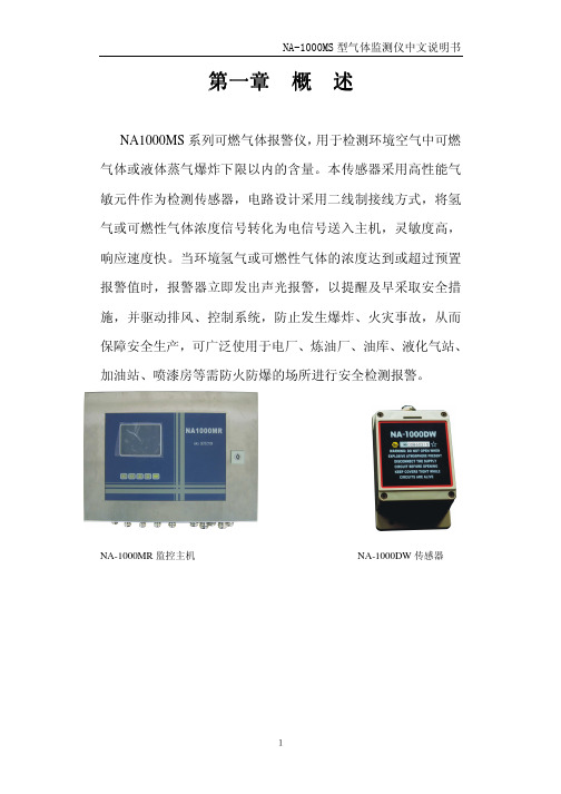
按键介绍如下图:
键盘的各个按键在实时显示画面和组态画面具有不同的功能。
8
NA-1000MS 型气体监测仪中文说明书
:左方向键;向左移动光标,选择参数; :右方向键;向右移动光标,选择参数;
数值.
:上方向键;向上移动光标,选择参数;变更设定时,用于减少
:下方向键;向下移动光标,选择参数;变更设定时,用于增加 数值
当前选择 的单位
当前时间
当前选择 的通道
当前显示 通道的报 警设置
所有通道 报警显示
当前日期
11
氢气纯度仪说明书

目录1.前言 (2)1.1 概述 (2)1.2 传感单元 (2)1.3 7866数字控制器 (3)1.4 操作原理 (6)2.技术参数和选型 (7)2.1技术参数 (7)2.2选型 (9)3.安装 (10)3.1 传感单元要求条件和定位 (10)3.2 安装传感单元 (10)3.3 管路连接 (10)3.4 传感单元与数字控制器接线 (11)4.设置模式 (13)4.1 概述 (13)4.2 结构概述 (13)4.3 单元设置组群 (13)4.4 报警设置组群 (14)4.5 ModBUS通讯设置组群 (15)4.6 校准组群 (15)4.7 状态组群 (15)5.校准 (17)5.1 概述 (17)5.2 传感单元校准 (17)5.3 7866分析仪输入校准 (17)5.4 (详见英文说明书)…………………………………………………………5.5 恢复工厂校准 (20)5.6 模拟输出校准 (20)5.7 安全锁定 (21)5.8 设置报警极限 (22)6.操作 (23)6.1 启动 (23)7.排除故障 (24)7.1 概述 (24)7.2 7866数字控制器检测 (25)附录 (26)1.前言1.1 概述美国HONEYWELL公司三范围H2和CO2分析仪/指示仪提供了发电机运转测量的三个过程:●范围1:CO2在Air(空气)中●范围2:H2在CO2中●范围3:H2在Air中7866氢气纯度分析仪由三个基本部件组成:传感单元(变送器),控制单元(接收器)(图1-1)和电源。
传感单元被安装到采样现场,数字控制器,装在无危险区域。
传感单元接受两或三种气体组成的混合气流,测出采样气体浓度,将一个电信号传给传感单元。
传感单元牢固的结构,可适应大多数恶劣环境,传感单元和控制单元间距最大可达1000英尺,用一条多芯非屏蔽电缆连接,既提高了系统的灵活性,又降低了安装成本。
图1-1 7866 数字分析仪连接的交联电缆将现场传感单元的输出信号传给控制单元,控制单元作为简易面板可安装在控制室内,如果条件允许,也可安装在采样现场。
氢气检漏法
氢气检漏法1、氢气检漏法的基本原理氢气检漏法是一种用5%的氢气和95%的氮气的混合气作为示踪气体进行检漏,称作氢氮混合气检漏法,或氢气检漏法。
5%氢气与95%氮气的混合气体是不可燃的(ISO10156国际标准),无毒性和腐蚀性,也不会对设备和环境产生不利影响。
氢气作为检漏使用的示踪元素,有着很多独一无二的优点。
氢的分子量与氦气相近,是所有化学元素中,分子量最小、最轻的元素,有很好的扩散性,逃逸性很强,吸附及粘滞性很低。
由于氢分子移动速度要高于其他分子,因此使用安全的低浓度氢气作为示踪气体,可以有着更快的响应速度和更好的检漏精度。
基本工作原理是使用新开发的氢气传感器,其采用的是催化反应和热电转换功能相结合的工作原理,将元件本身产生的电压转换成信号,不仅提高了可检测浓度范围,还不易受到外界温度的影响。
新开发的热电式氢气传感器由热电转换膜及其表面上部分形成的铂触媒膜组成,氢与触媒的发热反应引起的局部温差,利用热电转换膜转换为电压信号。
只要使用高性能的热电材料就可得到足以完成检测任务的信号。
氢气检漏法只对其示漏气体氢气有响应信号,而对其他气体没有响应,属于唯一性检漏性检漏方法。
一旦出现信号响应,说明有氢气通过漏孔进入被检件中,从而指示漏孔的位置与大小。
2、氢气检漏法主要设备(1)、检漏仪:日本扶桑的FER-H2DV和FER- H2DC检漏仪器内部结构坚实、可靠,无需进行保养、维护,因此特别适用在制冷行业及其他工业制造环境中。
此产品已经在中国三花集团、LG、三星、泰国东芝冰箱等客户中适用,相信它将在制冷行业中有很大的作为。
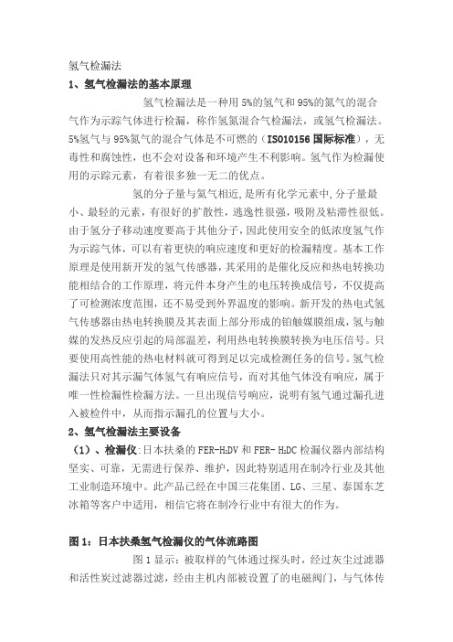
图1:日本扶桑氢气检漏仪的气体流路图图1显示:被取样的气体通过探头时,经过灰尘过滤器和活性炭过滤器过滤,经由主机内部被设置了的电磁阀门,与气体传感器接触。
流量经过传感器后部的流通量传感器进行数字处理后,在液晶显示器上表示出来。
同时,流量的控制用主机后面的针形电子管进行控制。
同时,氢气传感器的流路根据电磁阀门将取样气体分为气体取样调查用和室内空气取样调查用两种,没被使用的气体传感器经从空气取样调查口发送空气,而使用中的气体传感器则保持同一状态。
CuO—Sn02纳米传感器的H2检测特性研究
3 . S t a t e G r i d C h o n g q i n g E l e c t r i c P o w e r C o mp a n y Ma i n t e n a c e Fi l i a l e , C h o n g q i n g 4 0 0 0 4 4, C h i n a) Abs t r a c t : H2 i s o n e o f t h e ma i n f a u l t c h a r a c t e r i s t i c g a s e s d i s s o l v e d i n t r a n s f o r me r o i l , whi c h( ; a l l i n d i e a t e t h e e l e c t r i c f a u l t s , s u c h a s h i g h e n e r g y d i s c h a r g e, s p a r k d i s c h a r g e a n d p a r t i a l d i s c h a r g e, a n d p a r t i a l o i l o v e r h e a t i n g ph e n o me n o n.
第3 4卷
第1 0期
仪 器 仪 表 学 报
Ch i n e s e J o u r n a l o f S c i e n t i f i c I n s t r u me n t
Vo 1 . 34 No. 1 0 0c t .2 01 3
2 0 1 3年 米 传 感 器 的 H2检 测 特 性 研 究
陈伟根 ,李倩 竹 ‘ , 徐 苓娜 ,彭 尚怡 ,刘 军
( 1 . 重庆大学输配 电装 备及 系统安全与新技术 国家重点实验 室
氢气查漏仪操作手册
前言电缆泄漏的氢气(H2)法检测技术是以瑞典TELECOMUNICATIONS公司,德国BUNDESPOST公司和其他一些公司多年电缆维修经验为基础的,结合了瑞典SENSISTOR AB公司研制和开发的现代化微电子传感器技术。
所以这些经验被用来开发一个比过去任何泄漏探测系统更有效、更可靠的综合泄漏定位系统。
SENSISTOR公司的氢气泄漏探测仪把气压法推向了一个新的高度,氢气(H2)法使气压法技术得以实现它所预期的目的。
本手册即是给潜在的用户介绍这中方法,也是给新用户一些有用的信息。
能否很好地使用SENSISTOR公司的氢气泄漏探测仪并不取决于对本手册的阅读,对于这一点,许多已用过该仪器的人员都知道,不过在你处理一些从未面临过的、十分困难的泄漏探测工作时,本手册可帮助你节约一些时间。
花半个小时读一读本手册中使你立即感兴趣的一些章节,在你外出处理一些特殊的泄漏探测的困难时,肯定会增强你的信心,我们希望你会发现实际工作起来比本手册所说的情况更简单。
我们SENSISTRO AB 公司将深深感激阁下对本手册提出意见和建议。
瑞典SENSISTRO 公司1.引言氢气法适用于无充填物的电话通讯电缆,如架空电缆、直埋电缆和管道电缆的泄漏的定位,本方法的三个步骤是:A.确定电缆泄漏故障的范围B.给电缆充灌示踪气体C.用氢气泄漏探测仪8012 对泄漏故障定位电缆故障范围的确定有一整套预定位常规,如绘制压力曲线图,气流量读数或阻抗测量。
给电缆充灌示踪气体的方法是以620毫巴的压强给最靠近可能有泄漏部位的给气阀灌气,若该处电缆上无气阀,则需要另行安装一个气阀。
电缆泄漏故障的定位方法是搜寻从泄漏处溢出的氢气,选择合适的氢气探头可使定位工作更方便,对此本手册有详细介绍,实际上泄漏故障的定位操作很容易,故而预定位检测的工作量可减到最小,有时候甚至不需要作预定位检测。
管道探头。
顾名思义它是用于管道电缆的泄漏的定位,方法很简单只需将它推入管道直至获得清晰的指示,此时探头顶部便已抵达泄漏部位,一点也不复杂,就像用一根长长的软吸管来吸允气体一样。
HFY—3氢分仪

一、概述HFY-3型氢分析仪是一种分体盘装式常量氢气的检测仪器,特别适用于氧气和其它惰性气体中氢含量的在线检测分析。
HFY-3型氢分析仪由一次仪表(变送器)和二次仪表(分析仪)组成,体积小、重量轻、结构合理、便于安装,采用的进口传感器,反应灵敏、精确度高。
该仪器采用单片机处理与控制,LED数码管数字显示被测样气中氢气的含量;当被测样气中的氢含量高于设定值时,仪器会自动报警;同时,继电器控制的常开触点接通,常闭触点断开;当被测样气中氢含量低于设定的值时,一切恢复常态。
HFY-3型氢分析仪变送器符合GB3836.1-2000和GB3836.4-2000标准有关规定,并经国家防爆电气产品质量监督检验中心检验合格;防爆标志为:ExiaⅡCT4。
二、主要技术参数⒈测量范围:0.00~2.00%H2;⒉不确定度:≤±1%F.S;⒊重复性:≤0.5%;⒋分辨率:0.01%H2;⒌响应时间:T90≤2分钟;⒍稳定性:零点漂移≤±1%F.S/7d;量程漂移≤±1%F.S/7d;⒎样气流量:400±10毫升/分;⒏触点容量:220VAC,1A/24VDC,2A;⒐报警响应:≤10秒;⒑输出电流:4~20mA或0~10mA可选;⒒传感器:进口电化学传感器,寿命约二年;⒓工作电源:~220V±10%,50HZ;⒔工作环境:温度:-5℃~+40℃;湿度:≤95%RH;⒕外形尺寸:变送器:142(宽)×142(高)×200(深);分析仪:160(宽)×80(高)×170(深);⒖开孔尺寸:变送器:135(宽)×135(高);分析仪:150(宽)×75(高);⒗防爆标志:ExiaⅡCT4;⒘重量:分析仪1.2kg,变送器0.8kg;⒙外配安全栅参数:Vo≤28VDC,Io≤93mA,Cp≤0.02uF,Lp≤1mH;三、工作原理和仪器的面板结构㈠仪器的工作原理HFY-3型氢分析仪的工作原理框图如下图所示。
氢气传感器
结果和分析 如图所示,FBG固定在玻璃基 板上细微的凹槽中,使得Pt 掺杂的WO3涂层可以固定在靠 近FBG的表面。这个涂层在氢 响应过程中从灰色变为黑色。
左图反应了涂层在氢响应过后 的形态,可以看出,该涂层是 由不同面积的纳米薄片组成。 纳米薄片的厚度大约为50nm, 具有很大的比表面,为氢响应 提供了一个很大的表面。而且, 纳米包层之间还有大量间隙, 可以确保氢气可以在涂层中的 扩散。
上图是固定在玻璃基板前后在不同温度下的波长偏移,实验 结果便是,固定前后的温度敏感性增加了一倍。
测试不同氢气浓度下FBG氢传感器的响应,发现随着氢气浓 度的下降,响应时间变长,和文献中的数据相比,其响应 速度有了很大提高,而且能够在较低的氢气浓度下响应。 而且随着氢气浓度的增加,FBG的中心波长偏移越大。
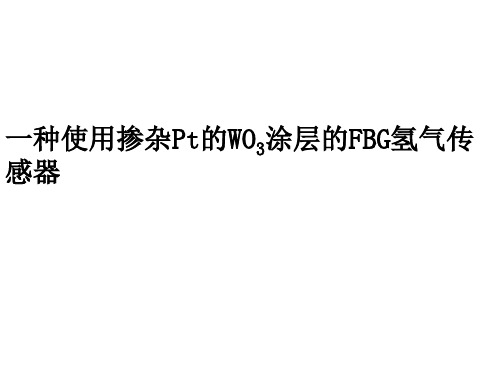
一种使用掺杂Pt的WO3涂层的FBG氢气传 感器
氢气传感器有很大的应用前景,这篇文章介绍了一种FBG氢 气传感器的制备和结果分析。 这种氢气传感器使用掺杂Pt的WO3涂层在FBG上制备而成, 其具有很快的响应速度和高的灵敏度,而且通过对结构进行优 化,能够在很低的(200ppm)的氢气浓度下响应。
因为环境湿度对FBG的影响可以忽略,而环境温度可 以通过辅助的FBG来测量。所以我们可以从这个模型中推 算出波长偏移和氢气浓度的关系。
总结: 的来说,这篇文章中报道的FBG氢气传感器通过结 合涂层和温度铭感的FBG而使得其性能有了很大提升。在 室温下,对于8000ppm的浓度的氢气具有448pm的波长偏移。 而且这种传感器可以检测最低到200ppm的氢气浓度,而且 在较低的温度下也能工作。
实验测量了在室温下不同环境湿度对响应时间和FBG波长偏移的 影响,发现在不同的环境湿度下,响应时间和波长偏移并没有 比较明显的改变。这说明,环境湿度的变化对这种FBG氢传感器 灵敏度影响不大。这是由于FBG氢传感器的结构疏松多孔,所以 具有比较好的抗湿度干扰能力。
美国H2SCAN公司-产品手册
产品应用
工厂或车间 过程泄漏 分析车间和控制室 储存罐和氢气运输
工业和大学实验室 氢气存储区域和传输管路 工作区域(通风柜和中试设备) 过程气泄漏
技术指标
量程
15ppm~100%(体积);无需外围设备
性能
工业防护等级 校准周期
IP64 1年
产品寿命 输入输出
输入 /接口
工作温度
10年 锂电池:工作时间10小时;
Capacitance
0.0015%
0.5%
H2 by Volume
产品优势
便携式氢气检漏仪量程:15ppm~100% 固定式氢气监测仪量程:4000ppm~5%(10%~125%LEL) 在线式氢气检测仪量程:0.5%~100% 抗其它气体干扰:CO、CO2、H2S、Cl2、N2、CH化合物、He、NH3;有氧或无氧 快速响应时间:2秒~10秒 介质气体温度:-20℃~100℃;相对湿度:0%~95%RH 对CH4等其它易燃气体无交叉敏感性,可消除误报警 多种输出方式:0~5VDC或4~20mA输出;RS422或RS232接口
产品应用
工厂或车间 过程泄漏 分析车间和控制室 储存罐和氢气运输
工业和大学实验室 氢气存储区域和传输管路 工作区域(通风柜和中试设备) 过程气泄漏
技术指标
量程
体积:0.4%~5.0%(10%~125%LEL)
精度
±(0.03×读数+0.2)百分比
性能
典型响应时间 工业防护等级
<60s IP66
校准周期
季冉实业公司
◆ 便携式氢气检漏仪 ◆ 固定式氢气监测仪 ◆ 在线式氢气分析仪 ◆ S F6红外气体传感器 ◆ CO2红外气体传感器
产品选型手册
气体传感器型号

电化学传感器ME2-C0一氧化碳CO0-1000ppmME3-CO一氧化碳CO0-500ppm,0-1000ppm,0-2000ppm ME4-CO一氧化碳CO0-500ppm,0-1000ppm,0-2000ppm ME3-H2S硫化氢H2S0-200ppmME4-H2S硫化氢H2S0-200ppmME3-H2氢气H20-200ppmME4-H2氢气H20-1000ppmME3-NH3氨气NH30-1000ppmME4-NH3氨气NH30-50ppmME3-CL2氯气CL20-50ppmME4-CL2氯气CL20-20ppmME3-PH3磷化氢PH30-20ppmME4-PH3磷化氢PH30-20ppmME3-O2氧气O20-25%max:30%ME2-O2氧气O20-25%max;30%ME3-C2H5OH酒精C2H5OH0-1000ppmME4-C2H5OH酒精C2H5OH0-1000ppm催化燃烧式可燃气体MC101甲烷、液化气、丙烷等可燃性气体0-100%LEL MC102甲烷、液化气、丙烷等可燃性气体0-100%LEL MC105甲烷、液化气、丙烷等可燃性气体0-100%LEL MC106甲烷、液化气、丙烷等可燃性气体0-100%LEL MC108氢气、可燃气体0-100%LELMC112甲烷、液化气、丙烷等可燃性气体0-100%LEL MC112D甲烷、液化气、丙烷等可燃性气体0-100%LEL MC113甲烷、液化气、丙烷等可燃性气体0-100%LEL MC114甲烷、液化气、丙烷等可燃性气体0-100%LEL MJC4/3.OL甲烷、瓦斯0-4%VOLMJC4/3.OJ甲烷、瓦斯0-4%VOLMJC4/2.8J甲烷、瓦斯0-4%VOLMJC4/2.5L甲烷、瓦斯0-4%VOLMC201甲烷、液化气、丙烷等可燃性气体0-100%LEL MC115甲烷、液化气、丙烷等可燃性气体0-100%LEL MC116甲烷、液化气、丙烷等可燃性气体0-100%LEL MC117甲烷、液化气、丙烷等可燃性气体0-100%LEL MC118甲烷、液化气、丙烷等可燃性气体0-100%LEL MC202甲烷、液化气、丙烷等可燃性气体0-100%LEL半导体式传感器MQ-2可燃气体、烟雾300to10000ppmMQ-4天然气、甲烷300to10000ppmMQ-5液化气、甲烷、煤制气300to5000ppmMQ-6液化气、异丁烷、丙烷100to10000ppmMQ-8氢气、煤制气50to10000ppmMQ306A液化气、甲烷、煤制气300to5000ppmMQ214甲烷300to5000ppmMQ216液化气、甲烷、煤制气100to10000ppmMQ-7一氧化碳CO10to1000ppmMQ307A一氧化碳CO10to500ppmMQ217一氧化碳CO10-1000ppmMQ-9一氧化碳、可燃气体10to1000ppm CO、100to10000ppm可燃气体MQ309A一氧化碳、可燃气体10to500ppm CO、300to5000ppm可燃气体臭氧O30.01-2ppmO3/10-500ppmO3氨气、苯、酒精、烟雾10-300ppmNH3、10-1000ppm苯、10-600ppm酒精、1%/-10%/m3烟雾MQ136硫化氢1-200ppmMQ137氨气10-300ppmMQ138醇类、苯类、醛类、酮类、酯类等有机挥发物5-5000ppm酒精(乙醇)10to1000ppmMQ303A酒精(乙醇)20to1000ppmMQ213酒精10-1000ppmMP-4天然气300to10000ppmMP-6液化气300to5000ppmMP-7一氧化碳10to1000ppmMP-8氢气50to10000ppmMP135氢气、酒精、CO一氧化碳10-100ppmH2、10-500ppm CO、10-1000ppm酒精离子烟雾传感器HIS-07二氧化碳气体敏感元件MG8110to10000ppm热传导气体敏感元件MD61天然气、液化气、煤气、烷类等可燃气体及汽油、醇、酮、苯、四氟化碳、氟里昂0-100%VOL热传导气体敏感元件MD62二氧化碳CO20-100%VOL热线型酒精气体敏感元件MR513酒精(乙醇)0to1000ppm热线型可燃气体敏感元件MR511甲烷、丁烷0to10000ppm。
MQ-2,MQ-4,MQ-5,MQ-6.MQ-8半导体式烟雾传感器
MQ-2,MQ-4,MQ-5,MQ-6.MQ-8半导体式烟雾传感器烟雾传感器的一般检测目标及检测范围MQ-2可燃气体、烟雾300 to 10000ppmMQ-4天然气、甲烷300 to 10000ppmMQ-5液化气、甲烷、煤制气300 to 5000ppmMQ-6液化气、异丁烷、丙烷100 to 10000ppmMQ-8氢气、煤制气50 to 10000ppm其它电化学传感器ME2-C0 一氧化碳CO 0-1000ppmME3-CO 一氧化碳CO 0-500ppm,0-1000ppm,0-2000ppmME4-CO 一氧化碳CO 0-500ppm,0-1000ppm,0-2000ppmME3-H2S 硫化氢H2S 0-200ppmME4-H2S 硫化氢H2S 0-200ppmME3-H2 氢气H2 0-200ppmME4-H2 氢气H2 0-1000ppmME3-NH3 氨气NH3 0-1000ppmME4-NH3 氨气NH3 0-50ppmME3-CL2 氯气CL2 0-50ppmME4-CL2 氯气CL2 0-20ppmME3-PH3 磷化氢PH3 0-20ppmME4-PH3 磷化氢PH3 0-20ppmME3-O2 氧气O2 0-25% max:30%ME2-O2 氧气O2 0-25% max;30%ME3-C2H5OH 酒精C2H5OH 0-1000ppmME4-C2H5OH 酒精C2H5OH 0-1000ppm催化燃烧式可燃气体MC101 甲烷、液化气、丙烷等可燃性气体 0-100%LELMC102 甲烷、液化气、丙烷等可燃性气体 0-100%LEL MC105 甲烷、液化气、丙烷等可燃性气体 0-100%LEL MC106 甲烷、液化气、丙烷等可燃性气体 0-100%LEL MC108 氢气、可燃气体 0-100%LELMC112 甲烷、液化气、丙烷等可燃性气体 0-100%LEL MC112D 甲烷、液化气、丙烷等可燃性气体 0-100%LEL MC113 甲烷、液化气、丙烷等可燃性气体 0-100%LEL MC114 甲烷、液化气、丙烷等可燃性气体 0-100%LEL MJC4/3.OL 甲烷、瓦斯 0-4%VOLMJC4/3.OJ 甲烷、瓦斯 0-4%VOLMJC4/2.8J 甲烷、瓦斯 0-4%VOLMJC4/2.5L 甲烷、瓦斯 0-4%VOLMC201 甲烷、液化气、丙烷等可燃性气体 0-100%LEL MC115 甲烷、液化气、丙烷等可燃性气体 0-100%LEL MC116 甲烷、液化气、丙烷等可燃性气体 0-100%LEL MC117 甲烷、液化气、丙烷等可燃性气体 0-100%LEL MC118 甲烷、液化气、丙烷等可燃性气体 0-100%LEL MC202 甲烷、液化气、丙烷等可燃性气体 0-100%LEL 半导体式传感器MQ-2 可燃气体、烟雾 300 to 10000ppmMQ-4 天然气、甲烷 300 to 10000ppmMQ-5 液化气、甲烷、煤制气 300 to 5000ppmMQ-6 液化气、异丁烷、丙烷 100 to 10000ppmMQ-8 氢气、煤制气 50 to 10000ppmMQ306A 液化气、甲烷、煤制气 300 to 5000ppmMQ214 甲烷 300 to 5000ppmMQ216 液化气、甲烷、煤制气 100 to 10000ppmMQ-7 一氧化碳CO 10 to 1000ppmMQ307A 一氧化碳CO 10 to 500ppmMQ217 一氧化碳CO 10-1000ppmMQ-9 一氧化碳、可燃气体 10 to 1000ppm CO、100 to 10000ppm可燃气体MQ309A 一氧化碳、可燃气体 10 to 500ppm CO、300 to 5000ppm可燃气体臭氧O3 0.01-2ppmO3/10-500ppmO3氨气、苯、酒精、烟雾 10-300ppmNH3、10-1000ppm苯、10-600ppm酒精、1%/-10%/m3烟雾MQ136 硫化氢 1-200ppmMQ137 氨气 10-300ppmMQ138 醇类、苯类、醛类、酮类、酯类等有机挥发物 5-5000ppm酒精(乙醇) 10 to 1000ppmMQ303A 酒精(乙醇) 20 to 1000ppmMQ213 酒精 10-1000ppmMP-4 天然气 300 to 10000ppmMP-6 液化气 300 to 5000ppmMP-7 一氧化碳 10 to 1000ppmMP-8 氢气 50 to 10000ppmMP135 氢气、酒精、CO一氧化碳 10-100ppmH2、10-500ppm CO、10-1000ppm酒精离子烟雾传感器 HIS-07二氧化碳气体敏感元件 MG811 0 to 10000ppm热传导气体敏感元件 MD61 天然气、液化气、煤气、烷类等可燃气体及汽油、醇、酮、苯、四氟化碳、氟里昂 0-100%VOL热传导气体敏感元件 MD62 二氧化碳CO2 0-100%VOL热线型酒精气体敏感元件 MR513 酒精(乙醇) 0 to 1000ppm热线型可燃气体敏感元件 MR511 甲烷、丁烷 0 to 10000ppm。
氢气检测仪选型说明及注意事项

一、概述:目前,各种气体燃料如天然气、液化石油气、城市煤气广泛地应用在家庭、工业场所,在的人们日常生活和工业生产带来方便的同时,也伴随着各种各样的安全隐患。
通常,可燃气体报警器报警点设置为被检测可燃气体爆炸下限的1%--25%范围内。
例如对于氢气,它的爆炸下限为4%,即4%=100%LEL=40000ppm, 相应氢气报警器的报警点范围应在1%LEL – 25%LEL之间,即0.04%(400ppm)—0.1%(10000ppm);若想增大安全系数,也可设定为1000ppm(0.01%).但是,一味地追求高灵敏度而降低报警设定点将会导致报警器的抗干扰能力变差,无危险的微量泄漏及环境温湿度或气氛的变化均会导致报警器的误报警,从而降低了报警系统的准确性、可靠性,这也是设定报警点时必须注意的。
一般氢气低限125PPM-750PPM 与上述不同的是,由于人工煤气含有高毒性的一氧化碳,毫无爆炸危险的少量泄漏即可引起致命的中毒事故,预防中毒往往成为人工煤气报警器监测泄漏的首要作用,报警点的设置应该充分考虑人工煤气的一氧化碳含量,将报警点设置于相当一氧化碳50PPM-300PPM的浓度范围。
二、检测原理:毒气/氧气检测仪器工作原理:传感器通常由三个电极构成,其中最主要的是工作电极。
它通常是用一种具有催化活性的金属,将其喷镀在一种透气但是憎水的膜上做成。
被测量的气体扩散透过多孔的膜在其上进行氧化或还原反应。
其反应的性质以工作电极的热力学电位和分析气体的氧化还原性质而定。
氧化还原反应中参加反应的电子,流向(还原)或流出(氧化)工作电极,通过外电路成为传感器的输出信号。
可燃气体检测仪工作原理:仪器所采用传感器是由两种传感器元件组成,一种为检测元件,另一种为补偿元件,两种元件都具有电热效应,分别构成电桥的两个桥臂。
当气体接触到传感器时,检测元件开始催化燃烧,补偿元件保持不变,因而电桥的桥臂阻值发生变化,产生一个失衡电压。
FAGIRO TGS 传感器 TGS822 有机溶剂蒸气检测用 说明书

TGS822 有机溶剂蒸气检测用特点: 应用:・对乙醇等有机溶剂有高灵敏度 ・酒精检测器・长期稳定性优良 ・工厂、干洗店、半导体产业的 ・长寿命、低成本 有机溶剂检知 ・以简单电路即可使用费加罗气体传感器的气敏素子,使用在清洁空气中电导率低的二氧化锡(SnO2)。
当存在检知对象气体时,传感器的电导率随空气中气体浓度增加而增大。
使用简单的电路即可将电导率的变化,转换为与该气体浓度相对应的输出信号。
TGS822传感器对酒精、有机溶剂的灵敏度高,在酒精检测器等方面得到广泛应用。
相同特性的TGS823,采用了陶瓷底座,可以在200℃的高温气氛中使用。
下图是典型的灵敏度特性,全部是在标准试验条件下得出的结果。
(请看背面)纵坐标以传感器电阻比(Rs/Ro )表示,Rs ,Ro 的定义如下:Rs =不同浓度气体中的电阻值 Ro =300ppm 乙醇中的电阻值灵敏度特性: 下图为受温度、湿度影响的典型曲线。
图中纵坐标也以传感器电阻比(Rs/Ro )表示,这里的Rs ,Ro 定义如下:Rs=含300ppm 乙醇、各种温/湿度下的电阻值 Ro=含300ppm 乙醇、20℃65%R.H.下的电阻值温/湿度的影响:SUNSTAR传感与控制 0755-********SUNSTAR传感与控制/TEL:0755-********FAX:0755-********E-MAIL:**************规格: 结构及尺寸:型 号 TGS822 素子类型 8系列标准封装塑料、SUS 双重金属网对象气体 酒精、有机溶剂 检测范围50~5,000 ppm 加热器电压VH 5.0±0.2V DC/AC 回路电压 VC MAX 24VPs ≦15mW标准回路 条件负载电阻 RL 可变 Ps ≦15mW 加热器电阻RH 38±3.0 Ω(室温) 加热器功耗PH 660±55mWVH =5.0V传感器电阻Rs300ppm 乙醇中 1~10K Ω 标准试验 条件下的 电学特性灵敏度(Rs 的变化率)0.4±0.1Rs(EtOH:300ppm)Rs(EtOH:50ppm)试验气体条件20±2℃, 65±5%RH 回路条件 VC =10.0±0.1V DC/AC VH =5.0±0.05V DC/AC RL=10.0 K Ω±1%标准试验 条件预热时间7天以上功耗(Ps)值可用下式计算: 传感器电阻(Rs ),可用下式计算:管脚连接 1或3:传感器4或6:传感器2 :加热器5 :加热器SUNSTAR传感与控制 0755-********SUNSTAR传感与控制/TEL:0755-********FAX:0755-********E-MAIL:**************FIGAROApplications:Features:TGS 822 - for the detection of Organic Solvent VaporsThe figure below represents typical sensitivity char-acteristics, all data having been gathered at standard test conditions (see reverse side of this sheet). The Y-axis is indicated as sensor resistance ratio (Rs/Ro) which is defined as follows:The figure below represents typical temperature and humidity dependency characteristics. Again, the Y-axis is indicated as sensor resistance ratio (Rs/Ro), defined as follows:Rs = Sensor resistance at 300ppm of ethanol* High sensitivity to organic solvent vaporssuch as ethanol* High stability and reliability over a longperiod* Long life and low cost* Uses simple electrical circuit* Breath alcohol detectors* Gas leak detectors/alarms* Solvent detectors for factories, dry clean-ers, and semiconductor industriesThe sensing element of Figaro gas sensors is a tin dioxide (SnO 2) semiconductor which has low conductivity in clean air. In the presence of a detectable gas,the sensor's conductivity increases depending on the gas concentration in the air. A simple electrical circuit can convert the change in conductivity to an output signal which corresponds to the gas concentration.The TGS 822 has high sensitivity to the vapors of organic solvents as well as other volatile vapors. It also has sensitivity to a variety of combustible gases such as carbon monoxide, making it a good general purpose sensor. Also available with a ceramic base which is highly resistant to severe environments as high as 200°C (model# TGS 823).IMPORTANT NOTE: RECOMMENDS CONSULTING OUR TECHNICAL STAFF BEFORE DEPLOYING FIGARO SENSORS IN YOUR APPLICATION AND, IN PARTICULAR, WHEN CUSTOMER’S TARGET GASES ARE NOT LISTED HEREIN. FIGARO CANNOT ASSUME ANY RESPONSIBILITY FOR ANY USE OF ITS SENSORS IN A PRODUCT OR APPLICATION FOR WHICH SENSOR HAS NOT BEEN SPECIFICALLY TESTED BY FIGARO.SUNSTAR自动化/TEL:0755-********FAX:0755-********E-MAIL:**************Structure and Dimensions:1 Sensing Element:SnO 2 is sintered to form a thick film on the surface of an alumina ceramic tube which contains an internal heater.2 Cap:Nylon 663 Sensor Base:Nylon 664 Flame Arrestor:100 mesh SUS 316 double gauzePin Connection and Basic Measuring Circuit:The numbers shown around the sensor symbol in the circuit diagram at the right correspond with the pin numbers shown in the sensor's structure drawing (above). When the sensor is connected as shown in the basic circuit, output across the Load Resistor (V RL ) increases as the sensor's resistance (Rs) de-creases, depending on gas concentration.Sensor Resistance (Rs) is calculated by the following formula:Rs = (-1) x R LV CV RL Power dissipation across sensor electrodes (Ps) is calculated by the following formula:Ps = 2V C x Rs 2(Rs + R L )Basic Measuring Circuit:REV: 9/99when the sensor is tested in standard conditions as speci-fied below:Test Gas Conditions:20°±2°C, 65±5%R.H.Circuit Conditions:V C = 10.0±0.1V (AC or DC),V H = 5.0±0.05V (AC or DC),R L = 10.0k Ω±1%Preheating period before testing: More than 7 daysFor information on warranty, please refer to Standard Terms and Conditions of Sale of Figaro USA Inc.17 ± 0.59.516.5±0.56.5±0.51.0±0.563425145˚45˚um : mmSUNSTAR自动化/TEL:0755-********FAX:0755-********E-MAIL:**************TGS822TF 人工煤制气检测用特点: 应用:・对煤制气中的氢气和一氧化碳有高灵敏度 ・家庭用、业务用煤制气报警器 ・乙醇等有机溶剂的干扰小 ・便携式煤制气检知 ・长寿命、低成本 ・以简单电路即可使用费加罗气体传感器的气敏素子,使用在清洁空气中电导率低的二氧化锡(SnO2)。
Unisense氢气传感器用户手册说明书

HYDROGEN SENSOR USER MANUALH ydrogen sensor user manual Copyright © 2021· Unisense A/S Version May 2021HYDROGEN SENSOR USER MANUALUNISENSE A/STABLE OF CONTENTS1: WARRANTY AND LIABILITY . . . . . . . . . . . . . . . . . . . . . . . . . . . . . . . . . . . . . . . . . . . . . . . .52: CONGRATULATIONS WITH YOUR NEW PRODUCT! . . . . . . . . . . . . . . . . . . . . . . . . . .6 2:1 S upport, ordering, and contact information63: OVERVIEW . . . . . . . . . . . . . . . . . . . . . . . . . . . . . . . . . . . . . . . . . . . . . . . . . . . . . . . . . . . . . . . . .84: GETTING STARTED . . . . . . . . . . . . . . . . . . . . . . . . . . . . . . . . . . . . . . . . . . . . . . . . . . . . . . . .9 4:1 u npacking a new SenSor9 4:2 p olarization9 4:3 c onnecting the microSenSor9 4:4 p re-polarization10 4:5 c alibration10 Zero hydrogen reading 10 Hydrogen reading 105: MEASUREMENTS . . . . . . . . . . . . . . . . . . . . . . . . . . . . . . . . . . . . . . . . . . . . . . . . . . . . . . . . .13 5:1 m ounting of the SenSorS13 5:2 e lectrical noiSe13 5:3 i nterference14 6: ADVANCED USE . . . . . . . . . . . . . . . . . . . . . . . . . . . . . . . . . . . . . . . . . . . . . . . . . . . . . . . . . .15 7: STORAGE AND MAINTENANCE . . . . . . . . . . . . . . . . . . . . . . . . . . . . . . . . . . . . . . . . . . . .16 7:1 c leaning the SenSor168: REFERENCES . . . . . . . . . . . . . . . . . . . . . . . . . . . . . . . . . . . . . . . . . . . . . . . . . . . . . . . . . . . . . .179: TROUBLESHOOTING . . . . . . . . . . . . . . . . . . . . . . . . . . . . . . . . . . . . . . . . . . . . . . . . . . . . . . . . . . . . . . . . . . . . . . . . . . . . . . . . . . . . . . . . . . . . . . . . . . . . . . . . . . . . . .18 41: WARRANTY AND LIABILITY1:1 n otice to p urchaSerThis product is for research use only . Not for use in human diagnostic ortherapeutic procedures .1:2 w arningMicrosensors have very pointed tips and must be handled with care toavoid personal injury and only by trained personnel .Unisense A/S recommends users to attend instruction courses to ensureproper use of the products .1:3 w arranty and l iabilityThe Hydrogen sensor is covered by a 90 days limited warranty .Microsensors are a consumables . Unisense will only replacedysfunctional sensors if they have been tested according with theinstructions in the manual within 14 days of receipt of the sensor(s) .The warranty does not include repair or replacement necessitated byaccident, neglect, misuse, unauthorized repair, or modification of theproduct . In no event will Unisense A/S be liable for any direct, indirect,consequential or incidental damages, including lost profits, or for anyclaim by any third party, arising out of the use, the results of use, or theinability to use this product .Unisense mechanical and electronic laboratory instruments mustonly be used under normal laboratory conditions in a dry and cleanenvironment . Unisense assumes no liability for damages on laboratoryinstruments due to unintended field use or exposure to dust, humidityor corrosive environments .1:4 r epair or a djuStmentSensors and electrodes cannot be repaired . Equipment that is notcovered by the warranty will, if possible, be repaired by Unisense A/Swith appropriate charges paid by the customer . In case of return ofequipment please contact us for return authorization .For further information please see the document General Terms of Saleand Delivery of Unisense A/S as well as the manuals for the respectiveproducts .52: CONGRATULATIONS WITH YOUR NEW PRODUCT!2:1 s upport, ordering, and contact informationThe Hydrogen microsensor is a miniturized sensor for measuringpartial pressure of H2in the micromolar range .If you wish to order additional products or if you encounter anyproblems and need scientific/technical assistance, please do nothesitate to contact our sales and support team . We will respond toyour inquiry within one working day .E-mail:******************Unisense A/STueager 1DK-8200 Aarhus N, DenmarkTel: +45 8944 9500Fax: +45 8944 9549Further documentation and support is available at our websitewww .unisense .com .REPLACEMENT OF SENSORSUnisense will replace sensors that have been damaged during shipment provided that:• The sensors were tested immediately upon receipt in accordance with the delivery note and the manual• The seal is still intact.• The sensors are returned to Unisense for inspection within two weeks.• The sensors are correctly packed for return to Unisense, in accordance with the note included in the sensor box.6673: OVERVIEWThis manual covers all the Unisense H2 and H2-X sensors . For a complete list of sensors sizes and types please go towww .unisense .com .The standard hydrogen sensor type, the H2-type, is for use in environments where H2S is not expected to occur . The H2S insensitive type, the H2-X-type, has an H2S trap in front of the H2 sensing part, allowing the sensor to be used in H2S containing environments (see “5:3 Interference”) .The Unisense hydrogen microsensor is designed for research applications within physiology, biotechnology, environmental sciences, and related areas .With the minute tip size, excellent response time, and good sensitivity the Unisense hydrogen sensor facilitates reliable and fast measurements with a high spatial resolution .The H2-X sensor has a slightly longer response time than the corresponding H2 sensor .The Unisense hydrogen microsensor is a miniaturizedClark-type hydrogen sensor with an internal reference electrode and a sensing anode . The sensor must be connected to a high-sensitivity picoammeter where the anode is polarized against the internal reference . Driven by the external partial pressure, hydrogen from the environment will pass through the sensor tip membrane and will be oxidized at the platinum anode surface . The picoammeter converts the resulting oxidation current to a signal .Schematic view of a hydrogen sensorwith a LEMO plug.IMPORTANT Unisense sensorsare neitherintended nor approved for use inhumans84: GETTING STARTEDThe H2-type and H2-X-type sensors are used in the same way . Only the sensitivity to H2S and the response time differ between the two types of hydrogen sensors .4:1 u npacking a new sensorWhen receiving a new microsensor remove the shock-absorbing grey plastic net .4:2 p olarizationThe signal from the hydrogen sensor is generated in picoampere . Therefore the hydrogen sensor must be connected to a polarizing picoammeter (e .g . a UniAmp series amplifier) .The anode of the hydrogen sensors should be polarized at +100 mV relative to the cathode . This happens automatically on the Unisense UniAmp series instruments . On the Unisense Multimeter, Monometer and PA-2000 instruments this must be set manually . Please consult the relevant the instrument manual for how to adjust polarization . If you are using a PA2000, please check the polarization voltage before connecting the sensor, since incorrect polarization may destroy the sensor .4:3 c onnecting tHe microsensorInsert the connector into a pA input terminal on the amplifier . The connector contains connections for both internal reference electrode and sensing anode .WARNING Do not remove the seal and protectiveplastic tube before these stepsand calibrationare succesfullycompleted.WARNINGIncorrect polarization may destroy the sensorNOTE The conversionof sensor signal in pA to amplifiersignal in mV is controlled by thePre-Amp Range (mV/pA) setting on the amplifer (notPA-2000)94:4 p re-polarizationJust after connecting the sensor, the signal will be very high and unstable then drop rapidly over the first few minutes . After that the signal will drop slowly for up to 1 hour . Therefore, a periodof polarization is necessary before you can use the sensor . This is called the pre-polarization period .The signal should stabilize at 0-10 picoampere (on the PA2000, the sign will be negative since sensor is positively polarized) forzero hydrogen concentration, depending on the specific sensor .If the sensor is new or has not been operated for several days, it must be polarized for at least 1 hour before it can be calibrated and used . After shorter periods without polarization, the sensor should be polarized until it has exhibited a stable signal for 10 minutes .The signal depends on the specific sensor type (see the value in the specifications that came with the sensor) .If the signal does not stabilize or is too high or too low, refer to the ‘Trouble-shooting’ section of this manual .4:5 c alibrationThe calibration procedure is the same for the H2 and H2-X sensors . Calibration must be performed after the sensor signal has stabilized during pre-polarization .z ero hydrogen readingPlace/keep the sensor tip in water and read the signal . This signal is your calibration value for zero hydrogen conditions .h ydrogen readingThe hydrogen sensor responds linearly and consequently atwo-point calibration is sufficient . Prepare water with a defined hydrogen concentration, which is slightly above the maximum expected concentration to be measured . A defined hydrogen concentration can be obtained by 2 different procedures:IMPORTANT Hydrogen sensorsare sensitive to temperature andsalinity,IMPORTANT Calibration must be performed after pre-polarization when the sensorsignal hasstabilized.Always usea calibration solution with the same temperature and salinity as the sample solution.101 . Use a gas mixture controller to obtain a defined mixture ofhydrogen and hydrogen free inert gas from a gas tank (e .g .N2) as bulk carrier gas . For instance, to obtain a hydrogenconcentration of 40,25 µM in the calibration chamber at 20°C, bubble the water in the calibration chamber vigorously witha gas mixture containing a 95 % N2 and 5 % H2 . The hydrogenpartial pressure is in this case 0 .05 atm, and the Solubility is 805 μmol/L/atm . Multiplying the solubility with the partialpressure results in the concentration: 805 µmol/L/atm * 0,05 atm = 40,25 µM .See Table 1 for more values of the solubility, or use the H2calculator in the Unisense SensorTrace Suite software .Start the software, click “Tools” and select “H2 calculator” . .For a Unisense CAL300 calibration chamber,5 minutes of bubbling at a rate of 5 l perminute is sufficient time to achieve 99 % of theconcentration . If the equipment (gas mixturecontroller) is available, this method can beconvenient, as you can switch between differentconstant hydrogen conditions without changingthe water . Use the solubility table (Table 1),or the H2calculator in the SensorTrace software to find the correct mixture at temperatures other than 20°C .To obtain correct concentrations, the headspace above thewater in the calibration chamber must be closed except fora hole only slightly larger than the microsensor shaft . Thiseffectively prevents ambient air from entering the vessel . We recommend the CAL300 Calibration Chamber for calibrations .2 . Add a defined volume of hydrogen-saturated water to adefined volume of water in a calibration chamber . For instance,1 ml of H2saturated water contains 0,805 µmol at 20°C (see Table 1), or the H2 calculator in the SensorTrace software,and to obtain water with a hydrogen concentration of 10 µM,3 .08 ml hydrogen-saturated water should be added to a totalvolume of 246,9 ml hydrogen free water in the calibrationWARNING Vigorous bubbling water with anygas may cause the water to coolconsiderably.Monitor the temperature tofind a suitablebubbling rate,which does notcool the watersignificantly.Calibration chamber CAL300chamber . After the addition of hydrogen-saturated water tothe calibration chamber mix it thoroughly by moving thesensor in its protection tube up and down for a few seconds and read the signal when it is stable . Do not stir bubbles into the water or mix by bubbling, as this will remove hydrogenfrom the water . A magnetic stirrer is not recommended asa mixing tool as a magnetic stirring can introduce electricalnoise to the signal . The hydrogen in the water will slowlyescape to the atmosphere and the concentration can only be considered constant for a few minutes .Hydrogen sensors respond linearly in the range of 0 to 100 %) and signals can be hydrogen (Low Range sensor from 0 - 10% H2linearly converted to partial pressure .Check and repeat calibration at appropriate intervals to ensure that all measurements can be converted to correct concentrations . When the sensor is new, the appropriate interval may be every2 hours; later it may be 24 hours . To minimize the need for calibrations, keep the sensor polarized between measurements, unless the time between measurements exceeds several days or unless the picoammeter batteries are running out . The membrane permeability of hydrogen microsensors changes with time, so a change in signal of up to 50 % may occur over months .If the sensor functions according to the criteria given in the delivery note, the seal and protective plastic tube can be carefully removed before making measurements.5: MEASUREMENTSThe H2-type sensor should be used in H2S free environments . If H2Sis expected to be present, the H2-X-type sensor should be used .Hydrogen sensors can be used for a wide variety of measurements(see our website for further information www .unisense .com) . Themost common use of hydrogen sensors is for making profiles ine .g . sediment or animal tissue where a high spatial resolution iswanted, or for hydrogen measurements in water samples .5:1 m ounting of tHe sensorsAlthough the Unisense microsensors are made of glass, the tipis flexible and can bend slightly around physical obstacles . Thesensor is thus rather sturdy in the longitudinal direction . However,large obstacles like stones or lateral movements of the sensorwhen the tip is in contact with a solid substrate may cause the tip Array to break .Furthermore, due to the small size of the microsensor tip andto the steepness of gradients in many environments, even adisplacement of the sensor tip of few microns may change itsenvironment .Therefore, we recommend that measurements should beperformed only in a stabilized set-up free of moving or vibratingdevices . We recommend the Unisense lab stand LS and theUnisense micromanipulator MM33 (MM33-2 or MMS) forMicromanipulator laboratory use . For in-situ use, we recommend our in situ stand(IS19) and a micromanipulator .5:2 e lectrical noiseThe signal of the microsensor is very small (10-13 to 10-10 ampere) .Although both the Unisense amplifiers and the UnisenseHydrogen microsensors are very resistant to electrical noise fromthe environment, electrical fields may interfere with the sensorsignal . Therefore, we recommend that unnecessary electrical/mechanical equipment is switched off and the sensor or wires arenot touched during measurements and signal recording .5:3 i nterferenceSulphide in the H2S form may interfere with the H2 measurements . The standard hydrogen sensor, the H2-type, is very sensitive to H2S and other reduced sulphur gases . It should, therefore, not be used in environments where H2S and other reduced sulphur gases are present . The H2-X sensor type is not sensitive to H2S up to 100 µM in solution or 1000 ppm H2S in gas . The H2S trap on the H2-X sensor works by removing protons from the H2S and the ionized formsof sulfide cannot pass through the silicone membrane into the H2 sensing part . Other sulphur gases where protons are less easily removed may still penetrate the silicone membrane . The H2-X sensor may, therefore, still be sensitive to other reduced sulphur gases than H2S . It is recommended to only expose the H2S-X sensor to H2S when needed, to maximize the lifetime of the H2S trap . The H2-X sensor may be made even more resistant to H2S . If you needacustombuiltsensor,*************************6: ADVANCED USEUnisense can construct hydrogen sensors for customer requested applications at additional costs . The most frequently requested construction options are described on our website www .unisense . com .The options include for instance customer specified dimensions, response time, stirring sensitivity, pressure tolerance, range and detection limit . If your specifications for a special hydrogen sensor is not described at our web page please contact sales@unisense . com for further options and prices .6:1 Examples of advanced applications• Consumption/production rates of hydrogen . E .g . during enzyme assays in small samples in Unisense microrespiration chambers MRCh• Measurements of hydrogen under high external pressuree .g . in closed pressurized systems, underwater and deep sea applications• Long-term hydrogen monitoringIfyouhavequestions,*******************************7: STORAGE AND MAINTENANCEStore the sensor in the protective plastic tube used for shipping . The hydrogen microsensor can be stored with the tip exposed to water or air . The room in which the hydrogen microsensor is stored should be dry and not too hot (10-30°C) . If the sensor is used regularly it can be stored polarized .7:1 c leaning tHe sensorDepending on which substance is present on the sensor tip or membrane, the sensor can be cleaned with different solutes .The standard method is to rinse with 96 % ethanol (NOT in the protection tube), then rinse with 0 .01 M HCl and rinse with water . This will remove most substances .Alternatively it is possible to rinse with 0 .1M NaOH, isopropanol or different detergents8: REFERENCES• Revsbech, N . P ., and B . B . Jørgensen . 1986 . Microelectrodes: Their Use in Microbial Ecology, p . 293-352 . In K . C . Marshall (ed .), Advances in Microbial Ecology, vol . 9 . Plenum, New York .• Itoh, T ., et al . 2009 . Molecular Hydrogen Suppresses FcepsilonRI-Mediated Signal Transduction and Prevents Degranulation of Mast Cells . Biochem . Biophys . Res . Commun . 389:651-656 .• Kajiya, M . et al . 2009 . Hydrogen From Intestinal Bacteria Is Protective for Concanavalin A-Induced Hepatitis . Biochemical and Biophysical Research Communications 386:316-321 .• Kajiya, M . et al . 2009 . Hydrogen Mediates Suppression of Colon Inflammation Induced by Dextran Sodium Sulfate . Biochemical and Biophysical Research Communications 386:11-15 .• Vopel, K ., et al . 2008 . Modification of Sediment-Water Solute Exchange by Sediment-Capping Materials: Effects on O2 and PH . Marine and Freshwater Research 59, 1101-1110 .Problem High and drifting signal .Possible cause The sensor tip is broken .Solution Replace the hydrogen microsensor .Problem The signal is very low .Possible cause Damage to internal working electrode .Solution Replace the hydrogen microsensor .Problem Very low sensitivity to H2 and low signal Possible cause 1Bubble in the narrow parts of the sensor,often not visible to naked eyeSolution 1Shake the sensor gently like shaking an oldmercury fever thermometerPossible cause 2Bubble in the sensor tip, not visible to thenaked eyeSolution2Soak the sensor in degassed water for atleast 2 hours . Degas water by boiling it andsubsequently cool it to room temperaturewithout getting air into it .Problem Slow response .Possible cause Insoluble compounds deposited at thesensor tip .Solution Rinse with 96 % ethanol, rinse with 0 .01 MHCl and rinse with water .Problem Unstable signal or the signal fluctuatesif the set-up is touched or equipment isbeing introduced in the medium you aremeasuring in .Possible cause Electrical disturbance of the sensorthrough the tip membrane .Solution Ground the set-up using the bluegrounding cable supplied with theamplifier . Connect the reference plug onthe amplifier (blue plug) with the mediumyou are measuring in .If you encounter other problems and need scientific/technical assistance, please contact **********************************(wewillansweryouwithinoneworkday)Table 1: Equilibrium hydrogen concentrations (µmol/litre) at ambient hydrogen partial pressure of 1 atm. in water as a function of temperature.Ref. Wiesenburg and Guinasso 1979. J.Chem Eng. Data 24(4):356-36021·*****************。
热失控h2传感器原理

热失控h2传感器原理
热失控H2传感器是一种广泛应用于氢气泄漏检测和火灾预警
系统的气体传感器。
它基于热传导原理工作。
传感器的基本结构通常由两个热敏电阻组成,一个作为探头(活性电阻)暴露在气体环境中,另一个用作参考(参考电阻)固定在恒温器中。
当氢气泄漏到探头电阻上时,氢气与空气周围形成了可燃混合物,导致热敏电阻上的温度升高。
热敏电阻的电阻值与温度呈负相关关系,因此当温度升高时,电阻值下降。
通过测量热敏电阻的电阻值变化,可以得知氢气的存在和浓度。
为了排除环境温度的影响,系统还需要一个参考电阻。
它被恒温器保持在恒定的温度下,它的电阻值不会随气体浓度变化而变化。
通过比较探头和参考电阻的电阻值,来确定氢气的存在和浓度。
通过将传感器输出与预设的氢气浓度阈值进行比较,可以触发警报或采取相应的控制措施,以便进行泄漏检测和火灾预警。
- 1、下载文档前请自行甄别文档内容的完整性,平台不提供额外的编辑、内容补充、找答案等附加服务。
- 2、"仅部分预览"的文档,不可在线预览部分如存在完整性等问题,可反馈申请退款(可完整预览的文档不适用该条件!)。
- 3、如文档侵犯您的权益,请联系客服反馈,我们会尽快为您处理(人工客服工作时间:9:00-18:30)。
H2氢气浓度传感器
H2氢气浓度传感器特点:
★整机体积小,重量轻
★高精度,高分辨率,响应迅速快.
★上、下限报警值可任意设定,自带零点和目标点校准功能,内置温度补偿,维护方便.
★数据恢复功能,免去误操作引起的后顾之忧.
★外壳采用特殊材质及工艺,不易磨损,易清洁,长时间使用光亮如新.
H2氢气浓度传感器技术参数:
★进口电化学传感器具有良好的抗干扰性能,使用寿命长达3年;
★采用先进微处理器技术,响应速度快,测量精度高,稳定性和重复性好;
★全量程范围温度数字自动跟踪补偿,保证测量准确性;
★半导体纳米工艺超低功耗32位微处量器;
★全软件自动校准,传感器多达6级目标点校准功能,保证测量的准确性和线性,并且具有数据恢复功能;★防高浓度气体冲击的自动保护功能
H2
氢气浓度传感器结构图:
H2氢气浓度传感器接线示意图
:H2氢气气体传感器参数
工作电压DC5V±1%/DC24±1%波特率9600
测量气体H2氢气气体检测原理电化学
采样精度±2%F.S响应时间<30S
重复性±1%F.S工作湿度10-95%RH,(无冷凝)工作温度-30~50℃长期漂移≤±1%(F.S/年)存储温度-40~70℃预热时间30S
工作电流≤50mA工作气压86kpa-106kpa
安装方式7脚拔插式质保期1年
输出接口7pIN外壳材质铝合金
使用寿命2年外型尺寸
(引脚除外)33.5X31 21.5X31
测量范围详见选型表
输出信号TTL(标配)0.4-2.0VDC(常规)/4-20mA 数字信号格式数据位:8;停止位:1;校验位:无;
传感器PIN脚定义图:
传感器应用场所:
医药科研、学校科研、制药生产车间、烟草公司、环境检测、楼宇建设、消防报警、污水处理、石油石化、化工厂、冶炼厂、钢铁厂、煤炭厂、热电厂、锅炉房、加气站、垃圾处理厂、隧道施工、输油管道、工业气体过程控制、室内空气质量检测、地下燃气管道检修、危险场所安全防护、设备检测等。
