三星硬盘跳线介绍IDE接口硬盘跳线的跳线设置方法
硬盘跳线设置图解
硬盘跳线设置图解设置跳线在电脑配件中,主板、硬盘、光驱、声卡都存在跳线,以主板跳线最为复杂,硬盘次之。
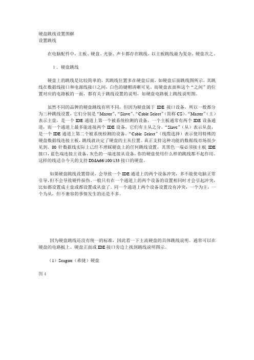
1.硬盘跳线硬盘上的跳线是比较简单的,其跳线位置多在硬盘后面,如硬盘后面跳线图所示。
其跳线在数据线接口和电源线接口之间,白色的键帽清晰可见。
而硬盘表面和这个“之间”的位置对应的电路板的一面,都有关于跳线设置的说明,如硬盘电路板上跳线说明图。
虽然不同的品牌的硬盘跳线有所不同,但因为硬盘属于IDE接口设备,所以一般都分为三种跳线设置,它们分别是“Master”、“Slave”、“Cable Select”(简称CS)。
“Master”(主)表示主盘,是一个IDE通道上第一个被系统检测的设备,一个主板通常有两个IDE设备通道,而一个通道上最多能连接两个IDE设备,它们有主从之分。
“Slave”(从)表示从盘,是一个IDE通道上第二个被系统检测的设备。
“Cable Select”(线缆选择)表示使用特殊的硬盘数据线连接主板,跳线就决定了硬盘的主从位置。
真正支持这种功能的数据线市场很少见到。
80针数据线实际上已经不理睬硬盘上的任何跳线设置,其黑色一端必须接主板IDE 接口,蓝色端连接主设备,灰色的一端连接从设备,你的硬盘使用什么样的跳线都不起作用。
这样的线适合今天的支持DMA66/100/133接口的硬盘。
如果硬盘跳线设置错误,会导致一个IDE通道上的两个设备冲突,多不能使电脑正常引导,但不会导致硬件损伤。
一般只有在一个通道上的两个设备的设置相同时才会引起冲突,比如都设置成主盘或都设置成从盘了。
同一个通道上两个设备设置没有冲突,一个为主,一个为从,但不兼容的事情发生的还是不多。
因为硬盘跳线还没有统一的标准,因此看一下主流硬盘的具体跳线说明。
通常可以在硬盘的电路板上、硬盘正面或IDE接口旁边上找到跳线说明图示。
(1)Seagate(希捷)硬盘图4Seagate硬盘的跳线设置图示一般可以在盘体的反面找到,短接的跳线被框上长方框,主要有四种设置方式:“Master or Single drive”(表示设置硬盘为主盘或该通道上只单独连接一个硬盘,即该硬盘独占一个IDE通道,这个通道上不能有从盘)、“Drive is slave”(表示当前硬盘为从盘)、“Master with a non-ATA compatible slave”(表示存在一个主盘,而从盘是不与ATA接口硬盘兼容的硬盘,这包括老式的不支持DMA33的硬盘或SCSI接口硬盘)、“Cable Select”(使用数据线选择硬盘主从)、无跳线(表示当前硬盘为从盘)。
双硬盘安装跳线设置方法图解
双硬盘安装跳线设置方法图解大家都知道,IDE设备(例如硬盘、光驱等)上都会使用一组跳线来确定安装后的主盘(Master,MA)、从盘(Slave,SL)状态。
如果在一根IDE数据线上接两个IDE设备的话,还必须分别将这两个IDE设备设置为一个为主盘,另一个为从盘状态。
这样,安装后才能正常使用。
小提示:如果一根IDE数据线上只接惟一的IDE设备,不管这个IDE设备原先是设置为主盘还是从盘状态,都不需要对这个惟一的IDE设备重新设置跳线。
通常都是将性能较好的新硬盘接在第一条IDE数据线上,设为主盘,作为开机引导硬盘。
至于旧硬盘,有几种接法:1.两个硬盘接在同一根硬盘数据线上,则第二硬盘应设为从盘。
笔者就以此方案为例。
2.第二硬盘接在第二个IDE接口上,如果该接口的数据线上只有一个硬盘,也没接光驱,那么第二硬盘就不用跳线;如果这根数据线上还挂有光驱,一般将第二硬盘和光驱的其中一个设为主盘,另一个设为从盘,这由你自己决定。
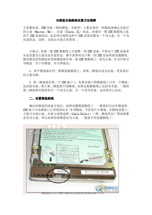
二、设置硬盘跳线确定好硬盘的连接方案后,就要设置硬盘跳线了。
一般我们可以在硬盘的IDE接口与电源接口之间找到由3~5列跳线。
不管是什么硬盘,在跳线设置上,大致可分成主盘、从盘与电缆选择(Cable Select)三种。
硬盘的出厂预设值都是设为主盘,所以如果你将硬盘设为主盘,一般就不用设置跳线了。
硬盘跳线大多设置在硬盘的电源插座和数据线接口之间笔者曾经看到一块三星硬盘的跳线是设置在硬盘背面的电路板上。
然后根据硬盘正面或数据线接口上方标示的跳线设置方法,如本例的希捷4.3GB硬盘正面就有跳线设置图三、安装硬盘与数据线打开机箱,将硬盘装入机箱的3.5英寸安装架,并用螺钉固定。
将第一根IDE数据线未端插入老硬盘的IDE接口,IDE数据线中端插入新硬盘的IDE接口,如图4所示。
而且,IDE数据线的Pin1(也就是红边)必须与硬盘和IDE接口的Pin1相连接。
最后再将梯形的四针电源插头接到硬盘的电源插座上。
硬盘跳线设置过程图解

双硬盘安装指南为了能容纳如今“体积”越来越大的软件,相信很多朋友都已购置了更高容量的新硬盘,但在你准备将老硬盘打入冷宫之际,是否想到过将两个硬盘一并使用呢,这不但可以免去让老硬盘提前退休,而且还可以让你拥有更大的硬盘空间,既然好处多多,那你还等什么?赶快加入我们的双硬盘安装之旅吧!一、安装前的注意事项安装双硬盘之前首先要查看电脑内部的基本情况,如是否还有安装第二个硬盘的空间,数据线有没有空余的接口,电脑电源功率是否能够支持两块硬盘的稳定运行等。
这些条件对于安装双硬盘来说都是很重要的。
二、跳线设置接下来是设置两个硬盘的跳线,一个设为主盘(Master Device),另一个设置为从盘(Slave Device)。
这里有一个问题大家要弄清楚,就是究竟哪个硬盘设置为主盘更合理,许多朋友认为要将容量更高的硬盘设为主盘,这种观点是错误的,正确的方法应该是将性能更好的硬盘设为主盘。
举个简单的例子,你本来有一块希捷酷鱼Ⅱ20GB硬盘(7200转),后来又添置了一块60GB的希捷U6硬盘(5400转),那么你就应该把酷鱼Ⅱ 20GB设为主盘,因为它的速度更快一些。
图1 酷鱼Ⅳ硬盘跳线说明不同的硬盘间的跳线方法可能会有所区别,但基本上大同小异。
下面我们就以一块希捷酷鱼Ⅳ(7200转)和一块迈拓星钻一代(5400转)为例,讲解一下跳线的设置方法。
图2 星钻一代硬盘跳线说明首先我们要分别看一下两个硬盘的跳线说明,这个说明一般位于硬盘的正面或反面(如图1、图2)。
然后按说明将希捷酷鱼Ⅳ设为主盘(如图3),将星钻一代设为从盘(如图4)(注:如果两个硬盘各使用一条数据线,则可以不进行跳线设置)。
完成跳线设置后,将两个硬盘分别安装到机箱内相应的位置,并连接好数据线和电源线。
在连接数据线时要注意将蓝色一端与主板的IDE接口相连,但如果你使用的是早期的DMA/33数据线,则无此要求。
完成这一步后,硬件上的安装工作就全部完成了。
接下来我们可以打开计算机的电源,并进入主板的BIOS,可以看到BIOS已自动检测出了两个硬盘的容量及主从关系,这说明双硬盘已安装成功。
图解跳线设置
图解跳线设置你知道DOS的命令参数吗?比如DOS的DIR命令的参数,使用DIR/P会显示一屏目录信息后暂停下来。
这些参数也被称作开关。
参数或开关给使用者以很大的灵活性,可以适应多种不同的需要!与软件一样,硬件也是有参数有开关可以设置的,硬件的设置开关就称为“ 跳线” (Jumper)。
熟练的掌握跳线是装机必备的技术之一。
一、了解跳线的类型迄今为止,跳线已经发展到了三代,分别是键帽式跳线、DIP式跳线、软跳线。
1.键帽式跳线键帽式跳线是由两部分组成:底座部分和键帽部分(如图1所示)。
前者是向上直立的两根或三根不连通的针,相邻的两根针决定一种开关功能。
对跳线的操作只有短接和断开两种。
当使用某个跳线时,即短接某个跳线时,就将一个能让两根针连通的键帽给它俩带上,这样两根针就连通了,对应该跳线的功能就有了。
否则,可以将键帽只带在一根针上,键帽的另一根管空着。
这样,因为两根针没有连通,对应的功能就被禁止了,而且键帽就不会丢失。
因为带键帽只表示接通,所以没有插反的问题。
键帽式的跳线分两针的和三针的,两针的使用比较方便,应用更广泛,短接就表示具有某个功能,断开就表示禁止某个功能;三针的比较复杂些,比如有针1、2、3,那么短接针1、2表示一种功能,而短接2、3表示另外一种功能。
2.DIP式跳线DIP式跳线也被称作DIP组合开关,DIP开关不仅可以单独使用一个按钮开关表示一种功能,更可以组合几个DIP开关来表示更多的状态,更多的功能。
如图2所示,DIP开关的一个可以两边扳动的钮就决定了两种开关状态,一面表示开(ON),另外一面表示关(OFF)。
而对于组合状态的使用,有多少DIP开关就能表示2的多少次幂的状态,就有多少个数值可以选择,因此,进入DIP开关时必须对照说明书中的表格设置数值,否则你根本搞不清楚这么多的状态。
3.软跳线软跳线并没有实质的跳线,也就是对CPU相关的设置不再使用硬件跳线,而是通过CMOS Setup程序中进行设置(如图3所示),根本不需要再打开机箱,非常方便。
IDE硬盘的主从盘跳线设置教程
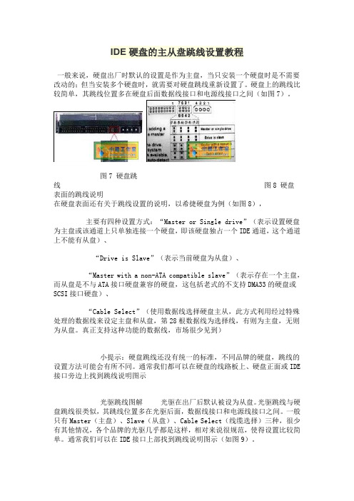
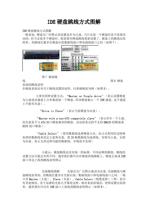
IDE硬盘的主从盘跳线设置教程一般来说,硬盘出厂时默认的设置是作为主盘,当只安装一个硬盘时是不需要改动的;但当安装多个硬盘时,就需要对硬盘跳线重新设置了。
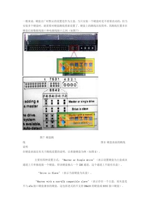
硬盘上的跳线比较简单,其跳线位置多在硬盘后面数据线接口和电源线接口之间(如图7)。
图7 硬盘跳线图8 硬盘表面的跳线说明在硬盘表面还有关于跳线设置的说明,以希捷硬盘为例(如图8),主要有四种设置方式:“Master or Single drive”(表示设置硬盘为主盘或该通道上只单独连接一个硬盘,即该硬盘独占一个IDE通道,这个通道上不能有从盘)、“Drive is Slave”(表示当前硬盘为从盘)、“Master with a non-ATA compatible slave”(表示存在一个主盘,而从盘是不与ATA接口硬盘兼容的硬盘,这包括老式的不支持DMA33的硬盘或SCSI接口硬盘)、“Cable Select”(使用数据线选择硬盘主从,此方式利用经过特殊处理的数据线来设定主盘和从盘,第28根数据线为选择线,有则为主盘,无则为从盘。
真正支持这种功能的数据线,市场很少见到)小提示:硬盘跳线还没有统一的标准,不同品牌的硬盘,跳线的设置方法可能会有所不同。
通常我们都可以在硬盘的线路板上、硬盘正面或IDE 接口旁边上找到跳线说明图示光驱跳线图解光驱在出厂后默认被设为从盘。
光驱跳线与硬盘跳线很类似,其跳线位置多在光驱后面,数据线接口和电源线接口之间。
一般只有Master(主盘)、Slave(从盘)、Cable Select(线缆选择)三种,很少有其他情况,各个品牌的光驱几乎都是这样,相对来说很规范,使得设置比较简单。
通常我们可以在IDE接口上部找到跳线说明图示(如图9)。
图9 光驱跳线说明小提示:如果光驱和硬盘共用一根IDE数据线,光驱跳线通常选择为Slave,硬盘则设为Master。
如果光驱是独立连接的IDE线,则可以大大方方地跳成Master。
IDE硬盘跳线设置
IDE硬盘跳线方式图解IDE硬盘跳线方式图解一般来说,硬盘出厂时默认的设置是作为主盘,当只安装一个硬盘时是不需要改动的;但当安装多个硬盘时,就需要对硬盘跳线重新设置了。
硬盘上的跳线比较简单,其跳线位置多在硬盘后面数据线接口和电源线接口之间(如图7)。
图7 硬盘跳线图8 硬盘表面的跳线说明在硬盘表面还有关于跳线设置的说明,以希捷硬盘为例(如图8),主要有四种设置方式:“Master or Single drive”(表示设置硬盘为主盘或该通道上只单独连接一个硬盘,即该硬盘独占一个IDE通道,这个通道上不能有从盘)、“Drive is Slave”(表示当前硬盘为从盘)、“Master with a non-ATA compatible slave”(表示存在一个主盘,而从盘是不与ATA接口硬盘兼容的硬盘,这包括老式的不支持DMA33的硬盘或SCSI 接口硬盘)、“Cable Select”(使用数据线选择硬盘主从,此方式利用经过特殊处理的数据线来设定主盘和从盘,第28根数据线为选择线,有则为主盘,无则为从盘。
真正支持这种功能的数据线,市场很少见到)小提示:硬盘跳线还没有统一的标准,不同品牌的硬盘,跳线的设置方法可能会有所不同。
通常我们都可以在硬盘的线路板上、硬盘正面或IDE接口旁边上找到跳线说明图示光驱跳线图解光驱在出厂后默认被设为从盘。
光驱跳线与硬盘跳线很类似,其跳线位置多在光驱后面,数据线接口和电源线接口之间。
一般只有Master(主盘)、Slave(从盘)、Cable Select(线缆选择)三种,很少有其他情况,各个品牌的光驱几乎都是这样,相对来说很规范,使得设置比较简单。
通常我们可以在IDE接口上部找到跳线说明图示(如图9)。
图9 光驱跳线说明小提示:如果光驱和硬盘共用一根IDE数据线,光驱跳线通常选择为Slave,硬盘则设为Master。
如果光驱是独立连接的IDE线,则可以大大方方地跳成Master。
硬盘跳线完全篇

硬盘跳线完全篇一、认识跳线不管是主板还是硬盘、光驱等驱动器,都能看到跳线身影。
那什么是“跳线”呢?所谓跳线,也就是镶嵌在主板、硬盘、光驱等设备上的金属接针(跳线柱),以及套在这些金属棍上的跳线帽。
跳线柱是一根根小金属柱,而跳线帽从外表来看是一个有两个“小孔”的塑料帽,不过跳线帽表层的这层塑料是用来起绝缘及保护作用的,它的里面有两块金属弹片所以当跳线帽插在跳线柱上时,这两根跳线柱之间就形成了一个“通路”。
跳线的作用是调整设备上不同电信号的通断关系,并以此调节设备的工作状态。
如确定CPU的工作电压、外频,驱动器的主从关系等等。
需要注意的是,一个跳线至少有两根跳线柱,但也可以有多根跳线柱。
从排列组合的角度来看,具备多根跳线柱的跳线(应该说是跳线组)能够调节的状态远比只有两根跳线柱的跳线要多,所以这种“跳线组”往往用在主板上,以此来调节CPU的外频、倍频等(用于超频)。
另外,很多主板上还有DIP开关设置,用以替代跳线帽,使用起来更为方便简单。
DIP开关右上角通常有“ON”标识,表明开关拨向上部时为接通“ON”状态(相当于跳线帽插入状态),向下则为断开“OFF”状态。
跳线非常重要,如果设置错误,轻则死机,重则损坏元器件,所以在调整跳线时一定要仔细阅读说明书,核对跳线名称、跳线柱编号和通断关系。
虽然不同设备的跳线设置方法不同,但也具备通用性,所以下面就让我们去认识并设置一些常见的跳线。
主板上需要设置“通断”关系的地方很多,所以这里也是跳线最多的地方,对于一个初学硬件的新手而言,正确设置主板上的跳线是必须掌握的技能。
二、设置CPU的标准外频目前CPU的标准外频只有66MHz、100MHz、133MHz这三挡,虽说目前的新型主板都支持“软跳线”,也就是通过“BIOS”来设置CPU的外频,但这种软跳线一般只能设置某个区段的非标准外频(用来超频),比如说将标准外频为100MHz的新赛扬超频到110MHz。
而如果要将100MHz外频的新赛扬超频到133MHz这样的标准外频,那往往得靠跳线才能完成。
两块硬盘 主从盘跳线详解

两块硬盘主从盘跳线详解随着硬盘价格的下降和需要安装软件的增多,许多人都采取了增加一个硬盘的方法来提高存储量。
不过安装双硬盘虽然在*作上比较简单,但是也有不少需要考虑的地方。
笔者根据自己的实践,提出以下几点注意事项。
1.主板上有两个IDE接口,最多可以安装四个IDE设备。
在安装双硬盘之前,必须先确定机箱中是否还有安装第二个硬盘的位置及电源功率是否够用。
2.如果将两个硬盘分别安装在两条数据线上,最好都设置成主盘方式。
如果受到条件限制而将两个硬盘安装在同一条数据线上时,应将两个硬盘分别设置成主盘和从盘。
在进行主、从盘设置时,可以参照以下两种方法进行:(1)由硬盘跳线设置:硬盘通常使用一组跳线来确定主、从盘的设置。
这组跳线通常由3组(6或者7)针或者4组(8或者9)针再加1~2个跳线帽组成,其位置也大多设置在电源连接座和数据线连接插座之间的地方。
另外,在每个硬盘的正面(或者反面)都印有关于主盘(Master)、从盘(Slave)以及由电缆选择(Cableselect)的跳线方法和标记说明。
(2)由硬盘跳线和40芯特制数据线配合设置:在设置这种主、从盘方式时,除了在硬盘跳线设置“电缆选择”方式之外,硬盘主、从状态的设置还取决于硬盘与硬盘数据线的连接插头,而能决定硬盘主、从状态的40芯硬盘数据线是特制的。
通常连接硬盘数据线中部插头的盘是主盘,连接在硬盘数据线端部插头上的盘就是从盘。
采用这种方法设置主、从盘时,首先必须将连接在同一条硬盘数据线的所有IDE接口设备(包括光驱等)跳线器设置在“电缆选择”位置,然后再根据实际情况而将主、从盘分别连接在相应的硬盘数据线插头上。
3.当不同品牌的硬盘在同一条硬盘数据线上使用时,有时会出现兼容性问题。
因此在添加硬盘时,应当尽量优先选择品牌相同的硬盘。
如果计算机启动时检测不到或者只检测到其中一个硬盘时,在确认两个硬盘地跳线设置都没有错误的前提下,可以先断开原来使用的硬盘,然后再重新开机。
常见IDE硬盘跳线

于Maxtor硬盘跳线>>> 星钻、金钻跳线图注:星钻三代D540X—4K 、金钻PLUS 8和金钻七代D740X—6L不属于此范围。
跳线图如下:左边是数据线接口,右边是电源线接口。
横着插的跳线帽不起作用,拔掉也可以。
除了主盘限制容量的跳线需两个跳线帽,其他情况一个帽就够了。
一般情况下:主盘跳线:跳J50从盘跳线:主板无法识别大硬盘时:先设置如下跳线,然后运行MaxBlast软件对硬盘分区格式化。
主盘跳线(限制容量):这种情况必须要两个跳线帽,跳J50和J46。
从盘跳线(限制容量):使用MaxBlast 3软件时,请不要用此跳线。
>>>美钻和金钻PLUS 8跳线图跳线图如下:左边是数据线接口,右边是电源线接口。
横着插的跳线帽不起作用,拔掉也可以。
除了主盘限制容量的跳线需两个跳线帽,其他情况一个帽就够了。
一般情况下:主盘跳线:跳J48从盘跳线:主板无法识别大硬盘时:先设置如下跳线,然后运行MaxBlast软件对硬盘分区格式化。
主盘跳线(限制容量):这种情况必须要两个跳线帽,跳J48和J44。
从盘跳线(限制容量):不推荐使用>>>昆腾盘体跳线图包括:金钻七代D740X—6L、星钻三代D540X—4K和其它昆腾盘体的硬盘。
跳线图如下:左边是数据线接口,右边是电源线接口。
横着插的跳线帽不起作用,拔掉也可以。
除了主盘限制容量的跳线需两个跳线帽,其他情况一个帽就够了。
一般情况下:主盘跳线:跳DS。
从盘跳线:PK可以拔去不用主板无法识别大硬盘时:先设置如下跳线,然后运行MaxBlast软件对硬盘分区格式化。
主盘跳线(限制容量):这种情况必须要两个跳线帽,跳DS和AC。
从盘跳线(限制容量):不推荐使用。
限制容量的跳线老主板不能识别大硬盘时,可以设置“主盘限制容量”的跳线,然后运行MaxBlast 3软件分区格式化硬盘,如果该软件能正确识别全部容量,您的问题就解决了。
介绍IDE接口硬盘跳线的跳线设置方法

介绍IDE接口硬盘跳线的跳线设置方法对大家推荐很好使用的硬盘跳线,像让大家对硬盘跳线有所了解,然后对硬盘跳线全面讲解介绍,希望对大家有用。
跳线虽然类型种类繁多,但它主要存在于主板、硬盘跳线、光驱这三大硬件中,在显卡、声卡等配件中比较少见。
下面大家就跟着学习跳线吧。
主板跳线跳线最多,最复杂的就是主板跳线了。
一般情况下,主板跳线主要包括CPU设置跳线、BIOS清除跳线、BIOS禁止跳线。
在这些跳线当中,CPU设置跳线最为复杂,它主要有CPU的倍频、外频、电压这三种跳线。
在主板上对应CPU倍频跳线的是一组跳线,每一种跳线都对应着一个倍频,根据自己的需要找到合适的倍频值(或跳线组合),然后拔下键帽短接它(或拔到ON处),这样倍频就设置好了。
同样的道理,在设置CPU的外频跳线与电压跳线时也一样,不过需要说明的是,有关CPU外频、倍频与电压设置是最为复杂的,而且每一块主板的设置也不大相同,所以建议大家在设置之前一定要认真阅读主板说明书,按照说明书中的具体说明进行实际操作,这样比较安全一些。
主板厂商为了减少用户的工作量,同时也为了吸引用户的眼球,早已将上面的有关CPU 的外频、倍频与电压跳线都移到主板BIOS设置中了,所以现在主板上已经比较难看到以上跳线了,有时看到也是三者中的一两个罢了。
在主板跳线中一直都存在着BIOS清除跳线。
当我们忘记BIOS密码时,最直接的办法就是打开机箱,找到BIOS清除跳线(它一般在主板电池旁边)进行清除。
通常情况下,清除BOIS信息时,只要将键帽从1、2针上拔下来,然后插在2、3针(表示清除BIOS 内容)进行清除,然后再将键帽重新插回到1、2针即可。
刚才我们向大家介绍了主板上的主要跳线,其实在主板上面还有一些小的跳线。
像键盘开机跳线等,具体情况就靠大家自己看主板说明书了。
为了方便大家,有些厂商还在主板上设置了在硬跳线与软跳线之间进行选择的跳线功能。
像华硕P4T的主板,如果我们将10个DIP开关全设置为“OFF”,这时我们就可以使用BIOS进行软跳线,否则,只有进行硬跳线了。
硬盘及光驱跳线设置图解指导说明
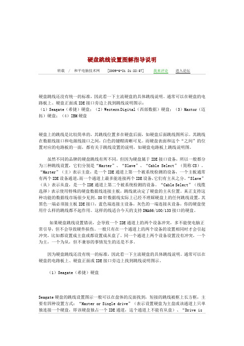
硬盘跳线设置图解指导说明转载/ 和平电脑技术网[2009-6-21 21:22:57] 我来评论进入论坛硬盘跳线还没有统一的标准,因此看一下主流硬盘的具体跳线说明。
通常可以在硬盘的电路板上、硬盘正面或IDE接口旁边上找到跳线说明图示:(1)Seagate(希捷)硬盘;(2)Western Digital(西部数据)硬盘;(3)Maxtor(迈拓)硬盘;(4)IBM硬盘硬盘上的跳线是比较简单的,其跳线位置多在硬盘后面,如硬盘后面跳线图所示。
其跳线在数据线接口和电源线接口之间,白色的键帽清晰可见。
而硬盘表面和这个“之间”的位置对应的电路板的一面,都有关于跳线设置的说明,如硬盘电路板上跳线说明图。
虽然不同的品牌的硬盘跳线有所不同,但因为硬盘属于IDE接口设备,所以一般都分为三种跳线设置,它们分别是“Master”、“Slave”、“Cable Select”(简称CS)。
“Master”(主)表示主盘,是一个IDE通道上第一个被系统检测的设备,一个主板通常有两个IDE设备通道,而一个通道上最多能连接两个IDE设备,它们有主从之分。
“Slave”(从)表示从盘,是一个IDE通道上第二个被系统检测的设备。
“Cable Select”(线缆选择)表示使用特殊的硬盘数据线连接主板,跳线就决定了硬盘的主从位置。
真正支持这种功能的数据线市场很少见到。
80针数据线实际上已经不理睬硬盘上的任何跳线设置,其黑色一端必须接主板IDE接口,蓝色端连接主设备,灰色的一端连接从设备,你的硬盘使用什么样的跳线都不起作用。
这样的线适合今天的支持DMA66/100/133接口的硬盘。
如果硬盘跳线设置错误,会导致一个IDE通道上的两个设备冲突,多不能使电脑正常引导,但不会导致硬件损伤。
一般只有在一个通道上的两个设备的设置相同时才会引起冲突,比如都设置成主盘或都设置成从盘了。
同一个通道上两个设备设置没有冲突,一个为主,一个为从,但不兼容的事情发生的还是不多。
硬盘跳线设置(Harddiskjumpersettings)
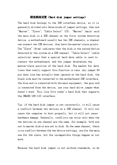
硬盘跳线设置(Hard disk jumper settings)The hard disk belongs to the IDE interface device, so it is generally divided into three kinds of jumper settings, they are "Master", "Slave", "Cable Select" (CS). "Master" (main) said the main dish is a IDE channel on the first system detection device, a motherboard usually has two IDE channels, a channel can connect two IDE devices, they have the master-slave points. The "Slave" (from) indicates that the disk is the second device detected by the system on a IDE channel. "Cable Select" (cable selection) means that a special hard data cable is used to connect the motherboard, and the jumper determines the master-slave position of the hard disk. The market for data lines that really support this function is rare. Any jumper 80 pin data line has actually been ignored on the hard disk, the black side must be connected to the motherboard IDE interface, the blue end is connected with the main equipment, the grey end is connected from the device, use your hard drive jumper what doesn't work. This line fits today's hard disk that supports the DMA66/100/133 interface.Tip: if the hard disk jumper is set incorrectly, it will cause a conflict between two devices on a IDE channel. It will not cause the computer to boot properly, but it will not cause hardware damage. Generally, conflicts can occur only when the two devices on one channel are the same, for example, both are set to master disk or are set to disk. On the same channel, there is no conflict between the two device settings, one for the main, one for the slave, but the incompatible things happen or not much.Because the hard disk jumper is not uniform standards, so welook at the mainstream hard disk specific jumper notes. Usually, we can find the jumper diagram on the hard disk circuit board, the front of the hard disk or the IDE interface.(1) Seagate (Seagate) hard disk (as shown in Figure 7)Screen.width-500) this.width=screen.width-500 border=0>Seagate hard drive jumper settings icon can be found on the opposite side of the tray body, short frame long jumper is Fang Kuang, there are four main ways: "Master or Single set drive" (hard disk or set mainly on that channel alone is connected with a hard disk, the hard disk is an exclusive IDE channel. This channel cannot from disk), "Drive is slave" (said the current hard disk from disk), "Master with a non-ATA compatible slave" (indicating the presence of a main dish, and from the disc is not compatible with the ATA interface hard disk drives, which include the old type does not support the DMA33 disk or SCSI hard disk interface), "Cable Select" (using the data line, select the hard disk master) no jumper (representing the current hard disk from the disk).(2) Western Digital (Western data) hard disk (shown in Figure 8)Screen.width-500) this.width=screen.width-500 border=0>Figure Western Digital hard drive jumper settings can be found in front of the tray body, short jumper is a rectangular block of black box, there are three main ways: set the "Slave" (said the current hard disk from disk), "Master w/Slave present"(representing the current disk disk from the disk, exist at the same time) "Single or Master" (set the channel on the disk or hard disk based solely connected to a hard disk, the hard disk is an exclusive IDE channel, this channel is not from disk).(3) Maxtor hard disk (as shown in Figure 9)Screen.width-500) this.width=screen.width-500 border=0>Maxtor hard drive jumper settings icon can be found on the front of the tray body, short jumper is painted black, there are three main ways: "set Master (Factory default)" (Master), Slave (Jumper Parking Position) "(from disk)," Cable select for Master/Slave "(cable select).(4) IBM hard disk (as shown in Figure 10)Screen.width-500) this.width=screen.width-500 border=0>The traditional hard disk only Master, Slave, Cable, Select three kinds of jumpers, individual hard disk combination more, and it is still inseparable from these concepts. But it is out of the ordinary IBM hard disk, the jumper is very complicated, the jumper settings can be found in the general graphic interface above, there are four main ways: "set Device 0 (Master)" (Master), Device 1 (Slave) "(from disk)," Cable Select "(cableselecting)," Forcing DEV 1 Present "(i.e. equipment 0 mandatory equipment 1, if your disk from old system can't tell the bus itself,You should set the main disk to this jumper.But these four kinds of setting mode can be set respectively in four different states: "15 Heads" (15 Heads for individual systems setting, hard drive capacity remains unchanged), "16 Heads" (the default disk is 16 Heads), "2/32GB CLIP" (the DJNA model of hard disk if the LBA pattern and the cylinder number of your BIOS more than 4096 of the hard disk is not compatible with the jumper excess cylinder ignored, let LBA use only 4096 cylinders, 2GB management space, there will be large when the 2GB hard disk usage. The capacity is less than 34GB DTLA or DPTA mode LBA mode and the hard disk, if the cylinder number of your BIOS more than 4096 of the hard disk is not compatible with the jumper excess cylinder ignored, let LBA use only 4096 cylinders, 2GB space management. That is, the big hard disk will be used by 2GB's hard disk. However, the column value displayed by the hard disk in the LBA mode does not change. The capacity is greater than or equal to 34GB DTLA or DPTA mode LBA mode and the hard disk, if the number of your BIOS sector more than 66055248 of the hard disk is not compatible with the jumper excess cylinder ignored, let LBA use only 66055248 sectors, 32GB space management. That is to use the big hard disk as 32GB's hard disk.) "Auto Spin Disable" (allows the hard disk to be awakened in the wait state).When your computer doesn't recognize the new hard disk, it is recommended that you change the default 16 Heads settings to "15 Heads" settings, and then change them to "2/32GB CLIP" settings.Tip: the hard disk jumper although clear, but points out which side is the beginning is not easy, there is a solution that candrive from the circuit board, the other one is to determine whether the correct settings on the hard drive in the boot information detection.3. drive jumperCD-ROM jumper and hard disk jumper is very similar, its jumper position in the CD-ROM behind, data line interface and power line interface, such as CD-ROM behind the jumper diagram. Generally only Master, Slave, Cable, Select three, rarely have other circumstances, the brand of CD-ROM is almost like this, relatively speaking is very standardized, so that the settings are relatively simple. Usually, we can find the jumper illustration diagram at the top of the IDE interface, as shown in figure 11.Screen.width-500) this.width=screen.width-500 border=0>After setting the drive, you can also check the information by booting self information. The general rule is to set the drive in the main disk position of the second channels. Although the CD-ROM settings in the master-slave disk location is not a problem, but if you want to install a burner or DVD drive, you can not set the normal boot error, so it is still better to master the correct method of setting.4. sound card jumperPCI sound card is generally only connected to the CD-ROM CD analog output interface of several audio line interface and SPDIF audio digital interface (with CD-ROM digital interface),there is no jumper required to set. The old ISA sound card jumper is relatively simple, usually only one or two jumpers, such as whether to use the sound card power amplifier to solve Mike incompatible jumper, as shown in Figure 12 of the JP1 jumper. When your Mike doesn't work properly on the sound card, you can try changing the jumper. The power amplifier (AMP) jumper, it said the power amplifier on the card, it is generally used in no power amplifier to the speaker, the speaker is now rarely used, so the jumper is not the meaning of existence.Screen.width-500) this.width=screen.width-500 border=0>How do I restore the registry?Q: how should the registry be restored if the registry is damaged? What are the main reasons for the damage to the registry?A: in addition to the human error to modify the registry, resulting in damage to the registry, the main performance of the following three aspects:1., software: mainly for applications, drivers are not compatible or contain errors, as well as damage to computer viruses.2., hardware: mainly for the quality of computer hardware or excessive overclocking, resulting in data reading and writing errors.3., misoperation: abnormal shutdown, is likely to cause damageto the registry or data loss. In order to prevent the registry error or damage, and affect the normal operation of the machine, usually should do the backup work of the registry. In fact, every time Windows starts up normally, the registry files are backed up. Backup the System.dat file to System.da0 and backup the User.dat file to User.da0. They are stored in the folder in which Windows is located, and attributes are "system" and "hidden". But this way of backup,It's not very safe. Because Windows 98 simply covers the last boot when each startup is started, the Windows 98 is backed up even if there is an error in the registry already. So you can use the backup tool of the registry editor to make a safe backup. In the registry editor, click the "my computer" and then click "file" menu, select "export registry file" menu item (Figure 1), select the path to save the export file, and then enter the new file name, the file extension for REG.Screen.width-500) this.width=screen.width-500 border=0>Tip: you can use any text editor to edit or view the.Reg file created by export.You can restore the registry if the computer does not start properly because the registry is corrupted. When the registry is broken, and if it can start to Windows, the system will automatically restore System.dat and User.dat with the automatically backed System.da0 and User.da0 files. If you can not recover automatically, then the operation of the registry editor, click the file menu, select "into the registry file menu item, browse the.Reg backup files to be added, and then click"open "button.If the registry is broken and the computer cannot start. At this point, you can restore the registry to the state of the last successful boot computer. Click "start" button, select "shut down the system menu, click restart computer and switch to the MS-DOS mode, and then click the" yes "button, enter the Scanreg /Restore at the MS-DOS prompt (Figure 2).Screen.width-500) this.width=screen.width-500 border=0>When you enter the interface, you will discharge the latest saved five registration data. After you select the registration data from the last computer that can successfully start the computer, press the "Restore" button to restart the computer automatically.Special attention: restore registry data must remember that in the extracted registry data saved after the date of various applications, hardware drivers and so on must also be re installed.Actual double hard disk installationFirst, determine the connection schemeAs you all know, IDE devices (such as hard disk, CD-ROM drive, etc.) will use a set of jumpers to determine the installed main disk (Master, MA), from the disk (Slave, SL) state. If two IDE devices are attached to one IDE data line, each of the two IDE devices must be set to one main disk and the other from the diskstate. In this way, you can use it properly after installation.Tip: if only one IDE device is attached to an IDE data line, no need to reset the jumper for the unique IDE device, regardless of whether the IDE device was originally a main disk or a disk state.The new hard disk is usually connected to the first IDE data line, and the main disk is set as the boot hard disk. As for the old hard disk, how many kinds do you have?:1. two hard disks are connected to the same hard disk data line, then the second hard disk should be set from the disk. The author takes this scheme as an example.2. second second hard disk connected to the IDE interface, the interface only if the data on a hard disk, also did not take CD-ROM, then second hard disk without jumper; if the data line is also linked to a CD-ROM, generally second hard disk and CD-ROM one mainly disc, another set from disk, it's up to you.Two, set the hard disk jumperDetermine the connection scheme of the hard disk, you have to set the hard disk jumper. In general, we can find 3~5 rows of jumpers between the IDE interface of the hard disk and the power interface. Whatever the hard disk, on the jumper settings, roughly divided into the main disk, from the disk and cable selection (Cable, Select) three. The factory defaults of the hard disk are based on the main disk, so if you set the hard disk as the main disk, you don't have to set up jumpers.The hard disk jumpers are mostly located between the hard drive socket and the data line interface, as shown in figure 1.Screen.width-500) this.width=screen.width-500 border=0>I once saw a Samsung hard disk jumper is set on the back of the hard disk circuit board. Then, according to the front of the hard disk or data line interface marked above jumper setting method, such as this example of Seagate 4.3GB hard disk front, there are jumper settings diagram, as shown in figure 2.Screen.width-500) this.width=screen.width-500 border=0>According to the settings shown in the diagram, remove all jumper caps from the disk, as shown in figure 3.[Three 、 install hard disk and data lineOpen the case and fit the hard disk into the 3.5 inch mounting frame of the case and fix it with screws. Insert the first IDE data line end into the IDE interface of the old hard disk, and insert the IDE interface of the new hard disk at the end of the IDE data line, as shown in figure 4. Also, the Pin1 of the IDE data line (that is, the red edge) must be connected to the Pin1 of the hard disk and the IDE interface. Finally, the trapezoidal four pin power plug is connected to the hard disk power socket.Screen.width-500) this.width=screen.width-500 border=0>Connect the IDE data line to the IDE slot of the motherboard, and also align the red edge of the IDE data line to the Pin1 of the IDE slot, as shown in figure 5. In general, there are two IDE slots on the motherboard, and the other end of the 80 pin or 40 pin IDE data line is inserted into the first IDE slot on the motherboard.Screen.width-500) this.width=screen.width-500 border=0>Tip: if your motherboard and hard disk support ATA 66/100/133, then you need to use the 80 pin IDE data line. Otherwise, if you use the 40 pin IDE data line (that is, the same as the CD-ROM data line), it will affect the hard disk transmission rate.Four, set the CMOS parameterFor new motherboards, the hard disk parameters are typically detected automatically. That is, as long as the hard disk is properly installed, there is no need to set up the CMOS. For some older motherboards, manual setup may be necessary.When you start your computer, press the "Del" button to enter the main menu of the CMOS Setup program. Select "IDE HDD Auto Detection (IDE hard drive automatic detection) and press enter, you can see all the parameters of the first and second hard disk, including capacity, the number of cylinders, heads, the number of sectors, working mode and so on. Test results show that the installation and setup of the dual hard disk have been successful. Press the "Esc" key to return to the main menu. Finally, press the shortcut key "F10" or select "Save And ExitSetup" (save out)". When you exit the CMOS Setup program, you restart the computer. If you can detect the hard disk parameters when you start the self test, the installation has been successful.As for how to use Fdisk to re partition the hard disk and use Format for the format of the hard disk partition, many articles have been introduced, no need to repeat it. But we must pay attention to the "letter goes" in format hard disk. For example, you will have a new hard disk is divided into three zones, the disk D, do not enter the "format D", but to enter the "format E", otherwise you can format the hard disk drive C old. It is recommended that you do not hook up the old hard disk before formatting your new hard drive to avoid this problem.In fact, the installation of double hard disk is relatively simple, as long as you can be careful, you can generally complete successfully. If your motherboard is older, after the installation of double hard disk, if you appear in the power on the self-test, you may crash, lock, or hard disk capacity display errors and so on. Well, it's probably the case with the legendary hard disk capacity limit.。
硬盘跳线设置
通常都是将性能较好的新硬盘接在第一条IDE数据线上,设为主盘,作为开机引导硬盘。至于旧硬盘,有几种接法:
1.两个硬盘接在同一根硬盘数据线上,则第二硬盘应设为从盘。笔者就以此方案为例。
screen.width-500)this.width=screen.width-500 border=0>
如何恢复注册表
问:如果注册表被损坏,应如何恢复注册表?注册表遭到破坏的原因主要有哪些?
答:除了人为错误地修改注册表外,造成注册表遭到破坏的原因主要表现以下三个方面:
(1)Seagate(希捷)硬盘(如图7所示)
screen.width-500)this.width=screen.width-500 border=0>
Seagate硬盘的跳线设置图示一般可以在盘体的反面找到,短接的跳线被框上长方框,主要有四种设置方式:“ Master or Single drive” (表示设置硬盘为主盘或该通道上只单独连接一个硬盘,即该硬盘独占一个IDE通道,这个通道上不能有从盘)、“ Drive is slave” (表示当前硬盘为从盘)、“ Master with a non-ATA compatible slave” (表示存在一个主盘,而从盘是不与ATA接口硬盘兼容的硬盘,这包括老式的不支持DMA33的硬盘或SCSI接口硬盘)、“ Cable Select” (使用数据线选择硬盘主从)、无跳线(表示当前硬盘为从盘)。
硬盘跳线大多设置在硬盘的电源插座和数据线接口之间,如图1所示。
硬盘属于IDE接口设备,所以一般都分为三种跳线设置,它们分别是“ Master” 、“ Slave” 、“ Cable Select” (简称CS)。“ Master” (主)表示主盘,是一个IDE通道上第一个被系统检测的设备,一个主板通常有两个IDE设备通道,而一个通道上最多能连接两个IDE设备,它们有主从之分。“ Slave” (从)表示从盘,是一个IDE通道上第二个被系统检测的设备。“ Cable Select” (线缆选择)表示使用特殊的硬盘数据线连接主板,跳线就决定了硬盘的主从位置。真正支持这种功能的数据线市场很少见到。80针数据线实际上已经不理睬硬盘上的任何跳线设置,其黑色一端必须接主板IDE接口,蓝色端连接主设备,灰色的一端连接从设备,你的硬盘使用什么样的跳线都不起作用。这样的线适合今天的支持DMA66/100/133接口的硬盘。
硬盘跳线介绍

硬盘跳一般来但当安线位置图在硬盘主要单独连 “Dr “Ma 接口硬 “Cab定主盘能的数小提有所不说明图光驱线位置跳线图解 来说,硬盘出装多个硬盘置多在硬盘后7 硬盘跳线盘表面还有关要有四种设置连接一个硬盘rive is Slave aster with a 硬盘兼容的硬ble Select”盘和从盘,第数据线,市场提示:硬盘同。
通常我示驱跳线图解置多在光驱后出厂时默认盘时,就需后面数据线线 关于跳线设置方式:“M 盘,即该硬e”(表示当non-ATA c 硬盘,这包(使用数据第28根数据场很少见到盘跳线还没有我们都可以解 光驱在出后面,数据硬盘认的设置是作需要对硬盘跳线接口和电源图8设置的说明,Master or Si 硬盘独占一个当前硬盘为从compatible s 包括老式的不据线选择硬盘据线为选择)有统一的标在硬盘的线出厂后默认据线接口和电盘跳线作为主盘,跳线重新设源线接口之8 硬盘表面以希捷硬ingle drive”个IDE 通道从盘)、slave”(表示不支持DM 盘主从,此择线,有则为标准,不同线路板上、认被设为从盘电源线接口介绍当只安装设置了。
硬盘之间(如图面的跳线说明硬盘为例(如”(表示设置道,这个通道示存在一个A33的硬盘此方式利用经为主盘,无品牌的硬盘硬盘正面或盘。
光驱跳之间。
一般一个硬盘时盘上的跳线7)。
明 如图8), 置硬盘为主道上不能有个主盘,而从盘或SCSI 接经过特殊处无则为从盘。
盘,跳线的设或IDE 接口跳线与硬盘跳般只有Mas 时是不需要线比较简单,主盘或该通道有从盘)、 从盘是不与接口硬盘)处理的数据线真正支持设置方法可口旁边上找到跳线很类似ster (主盘)要改动的;其跳道上只与ATA 、 线来设持这种功可能会到跳线似,其跳)、Slave (乎都是到跳线 图 小提则设为设(Slave 理,许该是将盘(72把酷鱼(从盘)、C 这样,相对 说明图示9 光驱跳线提示:如果Master 。
【推荐下载】硬盘跳线接法 超级简单易学不看后悔!!!
[键入文字]
硬盘跳线接法超级简单易学不看后悔!!!
真正的跳线是两根/三根插针,上面有一个小小的“跳线冒”那种才应该叫做“跳线”,它能起到硬件改变设置、频率等的作用;而与机箱连线的那些插针根本起不到这个作用,所以真正意义上它们应该叫做面板连接插针,不过由于和“跳线”从外观上区
别不大,所以我们也就经常管它们叫做“跳线”。
首先我们来更正一个概念性的问题,实际上主板上那一排排需要连线的插针并不叫
做跳线,因为它们根本达不到跳线的功能。
下面小编为大家介绍硬盘跳线接法的相关
知识。
1、电源开关连接线
连接电源开关连接线时,先从机箱面板连线上找到标有power sw 的两针插头,分别是白棕两种颜色,然后插在主板上标有pwr sw 或是RWR 字样的插针上就可以了。
2、复位开关连接线
用来热启动计算机用的。
连接时,先找到标有RESET SW 的两针插头,分别是白蓝两种颜色,然后插在主板上标有Reset sw 或是RSR 字样的插针上就可以了。
3、电源指示灯连接线
1。
CMOS路线和硬盘光驱跳线的设置图解教程
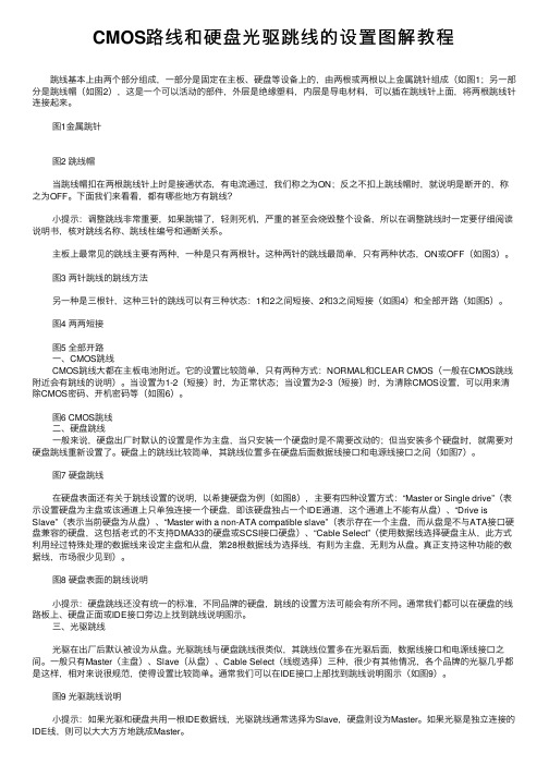
CMOS路线和硬盘光驱跳线的设置图解教程 跳线基本上由两个部分组成,⼀部分是固定在主板、硬盘等设备上的,由两根或两根以上⾦属跳针组成(如图1;另⼀部分是跳线帽(如图2),这是⼀个可以活动的部件,外层是绝缘塑料,内层是导电材料,可以插在跳线针上⾯,将两根跳线针连接起来。
图1⾦属跳针 图2 跳线帽 当跳线帽扣在两根跳线针上时是接通状态,有电流通过,我们称之为ON;反之不扣上跳线帽时,就说明是断开的,称之为OFF。
下⾯我们来看看,都有哪些地⽅有跳线? ⼩提⽰:调整跳线⾮常重要,如果跳错了,轻则死机,严重的甚⾄会烧毁整个设备,所以在调整跳线时⼀定要仔细阅读说明书,核对跳线名称、跳线柱编号和通断关系。
主板上最常见的跳线主要有两种,⼀种是只有两根针。
这种两针的跳线最简单,只有两种状态,ON或OFF(如图3)。
图3 两针跳线的跳线⽅法 另⼀种是三根针,这种三针的跳线可以有三种状态:1和2之间短接、2和3之间短接(如图4)和全部开路(如图5)。
图4 两两短接 图5 全部开路 ⼀、CMOS跳线 CMOS跳线⼤都在主板电池附近。
它的设置⽐较简单,只有两种⽅式:NORMAL和CLEAR CMOS(⼀般在CMOS跳线附近会有跳线的说明)。
当设置为1-2(短接)时,为正常状态;当设置为2-3(短接)时,为清除CMOS设置,可以⽤来清除CMOS密码、开机密码等(如图6)。
图6 CMOS跳线 ⼆、硬盘跳线 ⼀般来说,硬盘出⼚时默认的设置是作为主盘,当只安装⼀个硬盘时是不需要改动的;但当安装多个硬盘时,就需要对硬盘跳线重新设置了。
硬盘上的跳线⽐较简单,其跳线位置多在硬盘后⾯数据线接⼝和电源线接⼝之间(如图7)。
图7 硬盘跳线 在硬盘表⾯还有关于跳线设置的说明,以希捷硬盘为例(如图8),主要有四种设置⽅式:“Master or Single drive”(表⽰设置硬盘为主盘或该通道上只单独连接⼀个硬盘,即该硬盘独占⼀个IDE通道,这个通道上不能有从盘)、“Drive is Slave”(表⽰当前硬盘为从盘)、“Master with a non-ATA compatible slave”(表⽰存在⼀个主盘,⽽从盘是不与ATA接⼝硬盘兼容的硬盘,这包括⽼式的不⽀持DMA33的硬盘或SCSI接⼝硬盘)、“Cable Select”(使⽤数据线选择硬盘主从,此⽅式利⽤经过特殊处理的数据线来设定主盘和从盘,第28根数据线为选择线,有则为主盘,⽆则为从盘。
硬盘跳线图解说明
一般来说,硬盘出厂时默认的设置是作为主盘,当只安装一个硬盘时是不需要改动的;但当安装多个硬盘时,就需要对硬盘跳线重新设置了。
硬盘上的跳线比较简单,其跳线位置多在硬盘后面数据线接口和电源线接口之间(如图7)。
图7 硬盘跳线图8 硬盘表面的跳线说明在硬盘表面还有关于跳线设置的说明,以希捷硬盘为例(如图8),主要有四种设置方式:“Master or Single drive”(表示设置硬盘为主盘或该通道上只单独连接一个硬盘,即该硬盘独占一个IDE通道,这个通道上不能有从盘)、“Drive is Slave”(表示当前硬盘为从盘)、“Master with a non-ATA compatible slave”(表示存在一个主盘,而从盘是不与ATA接口硬盘兼容的硬盘,这包括老式的不支持DMA33的硬盘或SCSI接口硬盘)、“Cable Select”(使用数据线选择硬盘主从,此方式利用经过特殊处理的数据线来设定主盘和从盘,第28根数据线为选择线,有则为主盘,无则为从盘。
真正支持这种功能的数据线,市场很少见到)小提示:硬盘跳线还没有统一的标准,不同品牌的硬盘,跳线的设置方法可能会有所不同。
通常我们都可以在硬盘的线路板上、硬盘正面或IDE接口旁边上找到跳线说明图示光驱跳线图解光驱在出厂后默认被设为从盘。
光驱跳线与硬盘跳线很类似,其跳线位置多在光驱后面,数据线接口和电源线接口之间。
一般只有Master(主盘)、Slave(从盘)、Cable Select(线缆选择)三种,很少有其他情况,各个品牌的光驱几乎都是这样,相对来说很规范,使得设置比较简单。
通常我们可以在IDE接口上部找到跳线说明图示(如图9)。
图9 光驱跳线说明小提示:如果光驱和硬盘共用一根IDE数据线,光驱跳线通常选择为Slave,硬盘则设为Master。
如果光驱是独立连接的IDE线,则可以大大方方地跳成Master。
设置两个硬盘的跳线,一个设为主盘(Master Device),另一个设置为从盘(Slave Device)。
IDE双硬盘设置跳线

双硬盘一般大家的电脑里都有一块硬盘,就是电脑的外部存储器,现在的硬盘小的有60G 大的上百G。
电脑升级换代飞快,现在的大型3D游戏、电影都需要大容量的硬盘。
一些老型号的电脑的硬盘容量已经跟不上形势。
双硬盘是电脑DIY者对自己在电脑里挂两块硬盘的称呼。
有的同志为了不把自己的老硬盘浪费,就买一个新的硬盘装在电脑里;有的同志纯粹是为了学习这一技术而去挂双硬盘。
IDE硬盘挂双硬盘实现原理:一般的电脑主板上都有两个大小一样的长方形的插槽,一个插着硬盘,另一个插着光驱。
我们想再插上另一个硬盘岂不是没地儿了?我们可以用一根数据线(上面有三个插槽的用来连接硬盘和主板的那种宽线,很常见的)一头插在主硬盘上,另一头插在从盘上,还有一个就可以插在主板上。
是不是很简单呀?还要注意的是,主盘和从盘要区分开需要跳线(如果是把两块硬盘接在一根线上,就要把装有XP的硬盘设为主,另一块设为从:接在两根数据线上,两块硬盘都要设为主)正确后进BIOS看看有没有显示两块硬盘,可以根据硬盘的跳线规则(硬盘背面印着呢)用一个超级小插头(用来把硬盘上的两根针接触到一起)来完成。
可能导致失败的问题:XP系如果上面的方法挂接失败了,可以试试右键点击“我的电脑”-“管理”-在左栏选择“设备管理器”-在右侧展开“IDE控制器”-分别双击“主要IDE控制通道”和“次要IDE控制通道”-选择“高级属性”选项卡-把设备0和设备1的“设备类型”都改为自动检测,把传输模式都改为DMA若可用-确定-重新启动电脑试试看这种问题出现的原因是因为在优化开机速度的时候把Windows系统的开机检测ID设备的过程禁用了,装好IDE设备后可以将这里改为“无”以加快系统启动速度,然而如果安装了新的IDE设备(这里我们加装了一块IDE硬盘)Windows就会置之不理,这种情况下,进BIOS 是看得到两块硬盘的,但进Windows后却看不到加装的硬盘o(∩_∩)o...盘符交错的解决方法下面,我们再说一下使用双硬盘时所经常出现的“盘符交错”问题。
硬盘跳线图解

硬盘跳线图解一般来说,硬盘出厂时默认的设置是作为主盘,当只安装一个硬盘时是不需要改动的;但当安装多个硬盘时,就需要对硬盘跳线重新设置了。
硬盘上的跳线比较简单,其跳线位置多在硬盘后面数据线接口和电源线接口之间(如图7)。
图7 硬盘跳线图8 硬盘表面的跳线说明在硬盘表面还有关于跳线设置的说明,以希捷硬盘为例(如图8),主要有四种设置方式:“Master or Single drive”(表示设置硬盘为主盘或该通道上只单独连接一个硬盘,即该硬盘独占一个IDE通道,这个通道上不能有从盘)、“Drive is Slave”(表示当前硬盘为从盘)、“Master with a non-ATA compatible slave”(表示存在一个主盘,而从盘是不与ATA接口硬盘兼容的硬盘,这包括老式的不支持DMA33的硬盘或SCSI接口硬盘)、“Cable Select”(使用数据线选择硬盘主从,此方式利用经过特殊处理的数据线来设定主盘和从盘,第28根数据线为选择线,有则为主盘,无则为从盘。
真正支持这种功能的数据线,市场很少见到)小提示:硬盘跳线还没有统一的标准,不同品牌的硬盘,跳线的设置方法可能会有所不同。
通常我们都可以在硬盘的线路板上、硬盘正面或IDE接口旁边上找到跳线说明图示光驱跳线图解光驱在出厂后默认被设为从盘。
光驱跳线与硬盘跳线很类似,其跳线位置多在光驱后面,数据线接口和电源线接口之间。
一般只有Master(主盘)、Slave(从盘)、Cable Select(线缆选择)三种,很少有其他情况,各个品牌的光驱几乎都是这样,相对来说很规范,使得设置比较简单。
通常我们可以在IDE接口上部找到跳线说明图示(如图9)。
图9 光驱跳线说明小提示:如果光驱和硬盘共用一根IDE数据线,光驱跳线通常选择为Slave,硬盘则设为Master。
如果光驱是独立连接的IDE线,则可以大大方方地跳成Master。
设置两个硬盘的跳线,一个设为主盘(Master Device),另一个设置为从盘(Slave Device)。
- 1、下载文档前请自行甄别文档内容的完整性,平台不提供额外的编辑、内容补充、找答案等附加服务。
- 2、"仅部分预览"的文档,不可在线预览部分如存在完整性等问题,可反馈申请退款(可完整预览的文档不适用该条件!)。
- 3、如文档侵犯您的权益,请联系客服反馈,我们会尽快为您处理(人工客服工作时间:9:00-18:30)。
不过在格式化硬盘时一定要注意“盘符交错”问题。例如你已将新硬盘分为三个区,格式化D盘时,千万不能输入“format D:”,而是要输入“format E:”,否则你只会格式化老硬盘的C盘。建议在格式化新硬盘之前不要挂接老硬盘,就可以避免这个问题了。
其实安装双硬盘的过程比较简单,只要你能细心一般就可以顺利完成。如果你的主板比较老,安装双硬盘之后,如果出现在通电自检时就可能死机、锁住,或者硬盘容量显示错误等现象。那么很可能是遇到了硬盘容量限制问题,可以通过一些软件来实现容量利用。
三星硬盘跳线介绍IDE接口硬盘跳线的跳线设置方法
大家都知道,IDE设备(例如硬盘、光驱等)上都会使用一组跳线来确定安装后的主盘(Master,MA)、从盘(Slave,SL)状态。如果在一根IDE数据线上接两个IDE设备的话,还必须分别将这两个IDE设备设置为一个为主盘,另一个为从盘状态。这样,安装后才能正常使用 。
四、设置CMOS参数
对于新的主板来说,一般都会自动检测硬盘参数。也就是说只要硬盘安装正确,就无须设置CMOS。对于一些老主板来说,可能就需要手动进行设置了。
启动计算机后,按“Del”键进入CMOS Setup程序的主菜单。选择“IDE HDD Auto Detection(IDE硬盘驱动器自动检测)”并回车,可以看到第一、第二硬盘的所有参数,包括容量、柱面数、磁头数、扇区数、工作模式等等。检测结果表明,双硬盘的安装和设置已经成功。按“Esc”键,退回到主菜单。最后按快捷键“F10”或选择“Save And Exit Setup(存盘退出)”。退出CMOS Setup程序后,将重新启动计算机,如果在开机自检时,能检测出硬盘参数就说明已安装成功。
打开机箱,将硬盘装入机箱的3.5英寸安装架,并用螺钉固定。将第一根IDE数据线未端插入老硬盘的IDE接口,IDE数据线中端插入新硬盘的IDE接口,如图4所示。而且,IDE数据线的Pin1(也就是红边)必须与硬盘和IDE接口的Pin1相连接。最后再将梯形的四针电源插头接到硬盘的电源插座上。
硬盘跳线大多设置在硬盘的电源插座和数据线接口之间
笔者曾经看到一块三星硬盘的跳线是设置在硬盘背面的电路板上。然后根据硬盘正面或数据线接口上方标示的跳线设置方法,如本例的希捷4.3GB硬盘正面就有跳线设置图。
硬盘跳线设置
根据图中标示的设置方案,取出所有跳线帽就是从盘了
三、安装硬盘与数据线
连接IDE排线
将IDE数据线接到主板的IDE插槽中,同样也要将IDE数据线的红边对准IDE插槽的Pin1,如图所示。一般来说,主板上会有两个IDE插槽,将80针或40针的IDE数据线的另一端插入这个主板上第一个IDE插槽中。
IDE排线另一端插入主板接口里
小提示:如果你的主板和硬盘都支持ATA 66/100/133,那么务必要使用80针的IDE数据线。否则,如果使用40针的IDE数据线的话(即与光驱的数据线相同),将会影响硬盘传输速率。
2.第二硬盘接在第二个IDE接口上,如果该接口的数据线上只有一个硬盘,也没接光驱,那么第二硬盘就不用跳线;如果这根数据线上还挂有光驱,一般将第二硬盘和光驱的其中一个设为主盘,另一个设为从盘,这由你自己决定。
二、设置硬盘跳线
确定好硬盘的连接方案后,就要设置硬盘跳线了。一般我们可以在硬盘的IDE接口与电源接口之间找到由3~5列跳线。不管是什么硬盘,在跳线设置上,大致可分成主盘、从盘与电缆选择(Cable Select)三种。硬盘的出厂预设值都是设为主盘,所以如果你将硬盘设为主盘,一般就不用设置跳线了。
小提示:如果一根IDE数据线上只接惟一的IDE设备,不管这个IDE设备原先是设置为主盘还是从盘状态,都不需要对这个惟一的IDE设备重新设置跳线。通常都是将性能较好的新硬盘接在第一条IDE数据线上,设为主盘,作为开机引导硬盘。至于旧硬盘,有几种接法:
1.两个硬盘接在同一根硬盘数据线上,则第二硬盘应设为从盘。笔者就以此方案为例。