LN20042Q1使用手册
岛津色谱工作站操作手册

2、单次分析………………………………………………………………………………………………8
2.0 项目的新建(选择)……………………………………………………………………… 8 2.1 建立新方法………………………………………………………………………………………9 2.2 LC 装置参数的设定………………………………………………………………………………9 2.3 执行单次分析……………………………………………………………………………………12 2.4 进行波形处理(峰检测)………………………………………………………………………17 2.5 设定定量处理参数(化合物表)………………………………………………………………21 2.6 单次分析的数据上执行定量处理………………………………………………………………25 2.7 单次分析数据的汇总处理………………………………………………………………………28
5 停止 LC 的运转………………………………………………………………………………………45
5.1 立即停止…………………………………………………………………………………………45 5.2 过一会儿停止……………………………………………………………………………………45
6 结束 LCsolution……………………………………………………………………………………47
目
录
前言…………………………………………………………………………………………………………1 操作说明书的使用………………………………………………………………………………………2 1、分析准备………………………………………………………………………………………………3
LN2000软件手册

过程控制站可采用冗余配置,无论是板级还是网络的冗余均为热备份的方 式,当运行设备出现故障时,系统将无须人工介入自动切换至热备用设备,并 通过工程师站或操作员站的监视画面显示出故障设备,提醒运行维护人员进行 必要处理,而使系统在个别设备发生故障时,仍能维持原有功能稳定运行,冗 余技术的采用大大提高了系统的可靠性和无故障运行时间。 重要信号采取三取二的处理方法
1.3.2 采用技术方面
巧妙利用通用技术 在 LN2000 系统中大量的采用了当代新型的通用技术,如:通用计算机、 操作系统(WINDOWS2000)、SQL 数据库等,使它具有十分丰富的可利用的 技术资源和简单易学的特点。另外,它也能够不断跟上更新技术的发展,补充 它的性能。 广泛采用标准化技术 LN2000 系统把一大批成熟的标准技术作为整个系统的基础。这些技术包 括:IEEE802.2 以太网通信结构及协议;符合 ISA 的图形结构和界面;标准计 算机接口及总线等,使系统能够十分容易与其它系统连接和系统更新。 大力推广新型技术 LN2000 系统把计算机技术、窗口技术、控制技术、网络技术等十分有效地 融合在一起,尤为重要的是把仿真技术与上述技术密切结合,大大方便了系统 设计与调试,使它具有友好的人机界面和优秀的过程控制功能,从而能够后来 居上,成为值得信赖的分散控制系统。
LN2000 分散控制系统 软件使用说明书
山东鲁能控制工程有限公司 2001 年 9 月
第一篇 系统综述
1. 概述
1.1 引言
LN2000 系统是山东鲁能控制工程公司新近推出的一种新型的分散控制系 统(DCS)。它继承和发扬了当今 DCS 的优点:控制功能分散、系统功能分散 及显示、操作、记录、管理集中的功能,而且更注意借助世界上先进的多种技 术如:计算机技术、CRT 图形显示技术、数据通信技术、先进和现代控制技术, 通过技术创新,形成了系统结构合理、控制功能完善的开放的新型分散控制系 统,集数据采集、过程控制、生产管理于一体,能够满足大、中小不同规模的 生产过程的控制和管理需求。
IM04L21B01-63ZH-C_010

第4条(保证)
1 横河软件产品是以其制造完成时的状态或其出厂时的状态提供给用户的。除存储媒体的破损或损坏外,横河及 提供方不承担瑕疵担保责任及其他一切保证责任。如用户发现横河软件产品的存储媒体有破损或损坏时,横河 仅在其出厂后12个月内, 对其进行无偿更换(仅限于用户承担将该软件的存储媒体送至横河指定经销点的费用的 情况。)。且在任何情况下,横河对横河软件产品在质量及性能上的无瑕疵,恰当性,正确性,可靠性,最新性等 不作任何的明示或暗示的保证。横河也不保证横河软件产品与其他软件的一致性及兼容性等。 横河根据自己的判断,认为有必要时,可以对横河软件产品实施版本升级(以下称“升级”) ,进行无偿或有偿 提供。但是,横河并不承担向用户提供升级服务或升级后的产品的义务。 根据不同的产品,横河有提供有偿维修服务的可能。维修服务的范围及条件依照横河的另行规定。但是,如果 宣传手册或一般规格书中没有明确记载,横河将最多对最新版本及前一版本进行维护。前一版本为升级后5年以 内的横河软件产品。另外,关于已经停售的横河软件产品,仅对停售后5年以内的产品实施维修服务。关于标准 品以外的横河软件产品,横河不负实施维修措施的义务。对非横河更改或修正的横河软件产品,横河一概不予 应对。
本合同适用于横河的以下产品及附带提供的相关资料(以下称“横河软件产品”)。除横河另行规定的情况外,本 合同也适用于横河提供的更新版的横河软件产品及功能增加版的横河软件产品。 目标产品:DAQSTANDARD for FX1000 (Model FXA120)
第2条(使用权的许可)
1 2 有关横河软件产品,用户须以支付另行商定的使用费为代价,且只可在与以下授权数相同台数的计算机上安装 横河软件产品。横河以许可用户自己使用为目的,授予用户非垄断,不可转让的使用权。 授权数:1台 除横河书面另行许可或规定的情况外,禁止用户实施以下行为。 (a) 复制横河软件产品(允许复制一份以备用为目的软件,但必须注意妥善保管复制软件。) (b) 将横河软件产品或其使用权销售、转租、分发、转让、抵押给第三方或授予第三方再使用权,以及使横河软 件产品通过信息网络传播或发送成为可能。 (c) 通过网络在指定电脑以外的电脑上使用横河软件产品。 (d) 通过转存、逆向汇编、逆向编译、反向工程等手段将横河软件产品转换为程序源代码及其他可读取的格式或 复制此类转换;通过更改或译成他种语言将横河软件产品转换为横河所提供的形式以外的任何形式或作此类 转换尝试。 (e) 解除或试图解除横河软件产品中使用或添加的保护装置(防复制保护装置)。 (f) 删除横河软件产品中显示的著作权、商标、标志及其他标示。 横河软件产品及与其相关的一切技术、计算方式、技术诀窍和程序是属于横河或授权于横河 再使用权或转让权 的第三方的固有财产及商业机密。横河软件产品的权利归横河或相关第三方所有。横河不作将该财产权利转移 或转让给用户的任何承诺。 不得将前款中所述的固有财产及商业机密及键代码提供给使用横河软件产品时所必须的用户方高级管理人员、 职员或与之相当的人员以外的第三方。并且用户应使这些相关人员严守保密义务。 本合同被终止或被解除时,向横河退还横河软件产品及其复制软件的同时,必须彻底删除电脑或存储媒体中的 复制软件。销毁保存了横河软件产品及其复制软件的存储媒体时,必须彻底删除存储媒体中保存的内容。 横河软件产品可能会包含横河从第三方(含横河的关联公司)获得的许可再使用权或转让权的软件程序(以下称 “第三方程序”)。有关第三方程序提供方(以下称“提供方”)规定了与本合同不同的使用许可条件时,优先适 用提供方另行提出的相应条件。第三方程序中,也可能含有用户直接从提供方获得使用权的程序。 横河软件产品中可能含有已公开的源代码软件(以下称“OSS”)。有关OSS,优先适用其另行被规定的条件。
LN2000功能手册-2数学运算
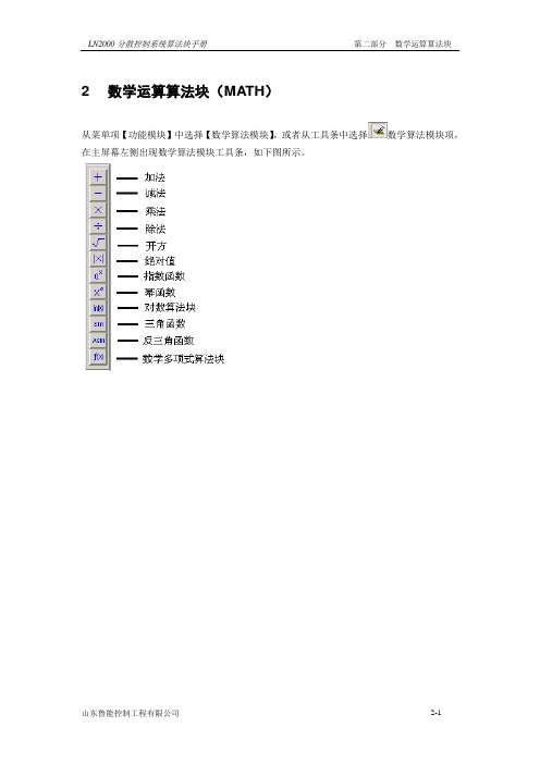
2 数学运算算法块(MATH)从菜单项【功能模块】中选择【数学算法模块】,或者从工具条中选择数学算法模块项,在主屏幕左侧出现数学算法模块工具条,如下图所示。
2.1加法算法块(ADD)Addition1、算法块图例2、算法块设置界面有外部连接的模拟量输入端无法手动修改初值,如上图中AI1和AI3两处;没有外部连接的输入端则可以修改初值,如上图中AI2和AI4两处。
3、算法块参数4、功能说明该算法完成加权加法的浮点运算,最多可以使用4个输入端。
5、算法说明悬空的输入端AI(i)初值默认为0。
AO=AI1*k1+AI2*k2+ AI3*k3+ AI4*k4。
2.2减法算法块(SUB)Subtraction1、算法块图例2、算法块设置界面有外部连接的模拟量输入端用户无法手动修改初值,如上图中AI1处;没有外部连接的输入端则可以修改初值,如上图中AI2处。
3、算法块参数4、功能说明该算法完成加权减法的浮点运算。
5、算法说明悬空的输入端AI(i)初值默认为0。
AO=AI1*k1-AI2*k22.3乘法算法块(MULT)Multiplication1、算法块图例2、算法块设置界面有外部连接的模拟量输入端用户无法手动修改初值,如上图中AI1处;没有外部连接的输入端则可以修改初值,如上图中AI2处。
3、算法块参数4、功能说明该算法完成加权乘法的浮点运算。
5、算法说明AO=(AI1*k1)*(AI2*k2)+Bias2.4除法算法块(DIV)Division1、算法块图例2、算法块设置界面3、算法块参数4、功能说明该算法完成加权除法的浮点运算。
5、算法说明AI2初值默认为1;初始化AI1,AI2,AO;若AI2=0,AO=AO(n-1)若AI2≠0,AO=(AI1*k1)/(AI2*k2)+Bias 注:AO(n-1)为前一采样时刻输出。
2.5开方算法块(SQRT)Square Root1、算法块图例2、算法块设置界面3、算法块参数4、功能说明该算法完成加权开方的浮点运算。
F24软件使用说明书

發射訊號模式 (Transmit Mode)
限 持續/不持續:當擇“持續”時是指當發射機“開機”後至“關機”之前,
不論是否按下任何按鍵,發射機均持續發射。當選擇“不持續”時是指
停用省電 (Save Power)
發射機停用關機 (Auto-OFF)
2
儲存檔案
儲存遙控器之設定及客戶資料時, 1 按下儲存鍵 2 選擇欲儲存位置及檔名後按下“存檔”鍵即可。
(按鍵功能設定表)
司
開啟舊檔
公
如需開啟舊檔時, 1 按下開啟舊檔鍵
限
2 選擇欲開啟位置及檔名後按下“開啟”鍵即可。
有
子
电
客戶資料
鼎
禹 客戶資料頁,可記錄客戶名稱,購買日期,地址,
電話等資料以供日後參考。 1 點選“客戶資料”。
有
燒錄新設定至遙控器
子
*使用軟體讀取發射機或接收機時,請確實關閉電源或取出電池後再執行讀取動作。 1 將 F24 軟體燒錄線(RS232) 接到發射或接收機。
电 2 按下“燒錄設定” 。 鼎 3 完成後按下“確定”鍵即可。
更改按鍵功能設定
禹 1. 首先讀取發射機(接收機) 之設定。
2. 於主畫面上點選欲更改之按鍵組(如箭頭處) ,此 時按鍵功能設定表即會顯示。
當發射機“開機”後,未按任何按鍵則發射機不發射信號,以節省耗電。
有 是指操作中發射器有一段時間未操作將進入停用狀態以節省用電。本
功能需在發射器為「持續發射」模式才有效,「不持續發射」時放開按
子 鍵即不耗電,故不需設定。
有效/無效﹕當選擇有效時是指發射機有一段時間未操作而進入停用
电 省電前,會發射急停信號使接收機進入關機狀態。
调节频率驱动AP03902004E的使用说明说明书
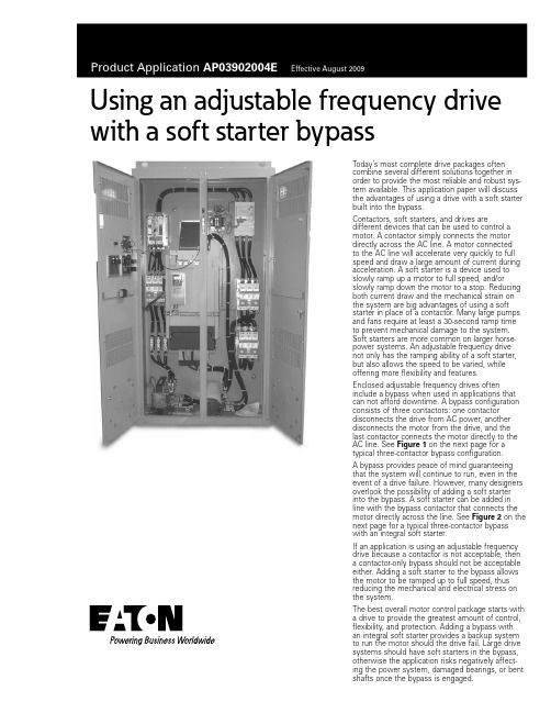
Using an adjustable frequency drive with a soft starter bypassToday’s most complete drive packages oftencombine several different solutions together inorder to provide the most reliable and robust sys-tem available. This application paper will discussthe advantages of using a drive with a soft starterbuilt into the bypass.Contactors, soft starters, and drives aredifferent devices that can be used to control amotor. A contactor simply connects the motordirectly across the AC line. A motor connectedto the AC line will accelerate very quickly to fullspeed and draw a large amount of current duringacceleration. A soft starter is a device used toslowly ramp up a motor to full speed, and/orslowly ramp down the motor to a stop. Reducingboth current draw and the mechanical strain onthe system are big advantages of using a softstarter in place of a contactor. Many large pumpsand fans require at least a 30-second ramp timeto prevent mechanical damage to the system.Soft starters are more common on larger horse-power systems. An adjustable frequency drivenot only has the ramping ability of a soft starter,but also allows the speed to be varied, whileoffering more flexibility and features.Enclosed adjustable frequency drives ofteninclude a bypass when used in applications thatcan not afford downtime. A bypass configurationconsists of three contactors: one contactordisconnects the drive from AC power, anotherdisconnects the motor from the drive, and thelast contactor connects the motor directly to theAC line. See Figure 1 on the next page for atypical three-contactor bypass configuration.A bypass provides peace of mind guaranteeingthat the system will continue to run, even in theevent of a drive failure. However, many designersoverlook the possibility of adding a soft starterinto the bypass. A soft starter can be added inline with the bypass contactor that connects themotor directly across the line. See Figure 2 on thenext page for a typical three-contactor bypasswith an integral soft starter.If an application is using an adjustable frequencydrive because a contactor is not acceptable, thena contactor-only bypass should not be acceptableeither. Adding a soft starter to the bypass allowsthe motor to be ramped up to full speed, thusreducing the mechanical and electrical stress onthe system.The best overall motor control package starts witha drive to provide the greatest amount of control,flexibility, and protection. Adding a bypass withan integral soft starter provides a backup systemto run the motor should the drive fail. Large drivesystems should have soft starters in the bypass,otherwise the application risks negatively affect-ing the power system, damaged bearings, or bentshafts once the bypass is engaged.Eaton Corporation Electrical Sector 1111 Superior Ave.Cleveland, OH 44114United States877-ETN-CARE (877-386-2273)© 2009 Eaton Corporation All Rights Reserved Printed in USAPublication No. AP03902004E / Z9003August 2009PowerChain Management is a registered trademark of Eaton Corporation. All other trademarks are property of theirrespective owners.Product Application AP03902004EEffective August 2009Using an adjustable frequency drivewith a soft starter bypassFigure 1. Typical Three-Contactor Bypass ConfigurationFigure 2. Typical Three-Contactor Bypass with Integral Soft Starter。
立林户户对讲系统2.0调试说明书
户户对讲系统使用说明书
一.简介
序号
产品型号
产品名称
1 JB-2000III
户户主机
2 JB-2000IIIG
户户刷卡主机
3 JB-2000IIIL
户户联网主机
4 JB-2000IIIGL
户户联网刷卡主机
5 JB-2000IIIM
户户可视主机
6 JB-2000IIIMG
户户可视刷卡主机
016——第五防区
002——第二防区
032——第六防区
004——第三防区
064——第七防区
008——第四防区
128——防拆防区(第八防区)
说明:① 有线防区代码由 001、002、004、008、016、032、064、128 组成;
② 输完该项后,按“*”键结束后按“99”或“099”+保安键对所有的分机进行确认。
动态≤410mA 工作电压:DC12V±10% 工作温度:-40℃~+70℃
2.1 系统示意图
二.安装说明
3P+2P(阀门控制)
水表 电表 煤气表
热能表
3P 红外探头烟感Fra bibliotek头5P V 2P 2P
18V 电源
门磁 紧急按钮
12V
123
456
78 9
*0#
保安
密码
2P 电源 电控锁
6P
RS232
V
备注:户户隔离器与视频分配放大器为选件。
2.3.4 设置用户密码(密码为门口主机密码键; 出厂用户密码为“1234”)
操作:密码 +“四位用户号”+ 密码 +“用户旧密码”+ 密码 +“用户新密码”+ 密码 说明:① 操作正确门口主机会有长“嘟”提示音,错误会有短“嘟、嘟”提示音;
共立2004中文使用说明书

⑴. 钳形传感器:通过导体获得被测电流。 ⑵. 钳口扳手:操作钳形传感器,按下扳手打开钳口。 ⑶. 直流电流零位调整钮:直流电流测量的零位调整。 ⑷. 交/直流滑动开关:选择交/直流电压和电流量程。 ⑸. 功能开关:选择电压、电流和电阻测量。
⑹. 电源/数据保持开关: 电源开关可打开或关闭电源,也是数据保持开关,便于微暗环境和难以 达到场所的数据读取。
上数据。 注意:仪器使用平均值矫正 RMS 读数的方法, 因而,正弦波电流测量中,可能发生测量错误。
20 或 200A 图3
5-3.电压测量 注意:● 注意请勿超量程输入,可允许最大输入电压值:200V DC 和 500V AC。
● 为避免迟点事故,测量电压时,请勿打开电池盒盖。
5-3-1.直流电压测量(200V DC)
拾取线圈 图 14
上海亿平仪器仪表有限公司
上海市浦东新区新金桥路 1088 号 A 座 1009 室 电话:021‐61728735 传真:021‐61294372 网址: 邮箱:sales@
⑺. 电流量程选择开关:选择电流测量范围。 ⑻. LCD 显示屏:3-1/2 位数字式液晶显示屏,最大指示值 1999,功能符号、单位和选择每项功能
和量程开关时十进制位数自动显示,低电压警告自动显示“B”标志,过量程警告显示“1”标 志(除交流电压量程) ⑼. COM 端口: 连接黑色测试线,测量电压和电阻,直流电压测量时是负电压输入端口。 ⑽. Ω电阻端口:电阻测量时,连接红色测试线,是正电压输出端口。 ⑾. VOLT 电压端口: 电压测量时,连接红色测试线,直流电压测量时,是正电压输入端口。 ⑿. 安全手套: 防止使用过程中仪器从手中滑落。
(可选件)增能器 M-8021、适配器 M-8004、8008
高纯氧化镍ittings系列LQ1、LQ2高精度插入工具使用说明书

PreparationParts case (1)Parts case (1)Parts case (3)Parts case (3)Parts case (2)Inner surfaceof the holderSET POS.Clamp so that the gap is equal on both sides.G a pSize reductionAttach the collar to the insert bushing for size reduction.Note)A collar cannot be attached afterinstallation has been completed.CollarInsert bushingTurn the lever to SET POS and fix it with the insert pin replacement screw.Fix the holder into the clamp with screws.Place the tubing on the holder and fix it.Attach the insert bushing to the insert pin.Attach the insert pin to the base.Press fit an insert bushingInsert bushingCollarInsert pin replacement screwInsert bushingInsert pinInsert pinHolderBaseInsert bushing for size reductionCollar (for size reduction)HolderScrew (attached both on top and bottom)ClampCautionTurn the handle slowly and press fit the insert bushing into the tubing.∗Dismantle the handle, slide the clamp until thetubing end touches the insert bushing, and fix it. Note)Note) J and K type clamps do not move.J type K typeToo much tubing protrusionBent tubingInsert bushing press fitted into tubingTubing finished by press-fittingon both sidesOptimum position Minimum positionInsert bushingTubingHandleNote) Too much tubing protrusion may cause breakage.Tubing length1. Do not allow the tubing to pro-trude too much from the holder when fixing the tubing position.2. Check the tubing for bending.1. Observe cautiously for tubing deflection and slippage.2. Press the insert bushing slowly into the appropriate position.CautionCaution∗ J-type clamps have a lever.Press fit an insert bushing∗ Before press-fitting, be sure to move the clamp to the appropriate position. (Refer to P2 .)Insert pin for short pipingNutTubing finished by press-fittingInsert pinInsert pinInsert pin for short pipingInsert bushingNut NutClamp Insert pin for short pipingClampHow to Order Insertion ToolsNote1)Replacement part type J is the part for LQ-GJ and LQ-GK.Replacement part type L is the part for LQ-GL and LQ-GM.Insert bushing press fitted into tubingNut tightening tool (LQ1 only) ∗ Use a commercially available tool to tighten the nut for an LQ2 fitting.Flared tubing jigInsert bushing jigNut tightening toolSeatSeatInsert bushing。
兰吉尔电度表ZQ中文用户手册(H01)

2.5.1
电表的测量系统采用模拟电流值I1、I2、I3和模拟电压值U1, U2, U3作为输入信号。
2.5.2
电压输入
高阻抗分压器把施加在电表上的电压U1、U2、U3(57.7伏至132.8伏)成比例地降低到几毫伏(UU),进行进一步处理。
电流输入
同样,补偿电流互感器也降低施加在电表上的输入电流I1、I2、I3(0 A至2 A或0 A至7.5 A)。这些电流互感器的次级电流提高负载电阻器的电压。上述电压值与输入电流成比例,也是几毫伏(UI)。
如果电表遭受到流动的水或高压装置的侵害,如冲洗等,电表可能会损坏。可以用湿布清洁电表。
更换电池
警告
换上了错误型号或额定电压的电池,可能会损坏电表。
只允许把电池更换为额定电压为6伏并与原电池(型号:CR-P2)结构相同的锂电池。
如果电表与供电网长时间断开,备用功率会耗尽。当备用功率耗尽时更换电池,可能会产生无效的时间/日期信息,但不会产生相应的错误信息。
可以更改电流互感器的负载电阻器,使电表量程与所需的电流范围(1安或5安)相匹配。
2.5.3
使用模数转换器把模拟输入信号UU和UI转换为数字值,并使用各种过滤器过滤。
接着,就可以获得所有三相的电压(U)和电流(I)的数字瞬间值,这些值用于信号处理器生成数字原始值。
2.5.4
每隔0.2秒,信号处理器计算一次有功电量、无功电量和视在功率以及各种瞬时量,如相电压和相电流等。一般说来,ZMQ的测量系统和ZCQ产生单相数据,而ZFQ提供其两个测量元件相应的数据。
这些值是经过校验的原始数据,它们存储在信号处理器的输出缓冲器中,通过一个SPI接口把它们从输出缓冲器传送到微处理器中进一步运算。
单相电量计算
WE04 2片镀膜钢球阀值规格-安装和运行说明书简章

Series WE04 2-Piece Flanged Stainless Steel Ball ValveSpecifications - Installation and Operating InstructionsBulletin V-WE04The SERIES WE04 incorporates a full port 2-piece flanged SS ball valve for great flow rates with minimal pressure drop. The valve features a blowout proof stem for added safety, reinforced PTFE seats and seals for longer life, and a 316 SS (ASTM CF8M) ball for better performance. Actuators are direct mounted creating a compact assembly for tight spaces. Limit switches are able to be mounted directly to the valves allowing for remote position indication.The Series WE04 can be configured with either a pneumatic or electric actuator. Electric actuators are available in weatherproof or explosion-proof, a variety of supply voltages, and two-position or modulating control. Two-position actuators use the supply voltage to drive the valve open or closed, while the modulating actuator accepts a 4 to 20 mA input for valve positioning. Actuators feature thermal overload protection and permanently lubricated gear train.The pneumatic double acting actuator uses an air supply to drive the valve open and closed. The actuator has two supply ports, with one driving the valve open, and the other driving the valve closed. Spring return pneumatic actuators use the air supply to open the valve, and internally loaded springs return the valve to the closed position. Also available is the SN solenoid valve to electrically switch the air supply pressure between the air supply ports for opening and closing the valve. Actuators are constructed of anodized and epoxy coated aluminum for years of corrosion freeservice.WE04-DHD00WE04-DTD01-AWE04-DDA02-NN09WE04-CTI01-ABy DwyerVALVE BILL OF MATERIALSVALVE DIMENSIONAL DRAWINGAUTOMATED VALVE DRAWINGSW/ PNEUMATIC ACTUATORW/ ELECTRIC ACTUATORW/ EXPLOSION-PROOF ELECTRIC ACTUATORPNEUMATIC ACTUATORNote: For optimal operation, pneumatic actuators should be run with a supply of clean, lubricated air.Spring Return Actuator OperationAir to PORT 2 (the left hand port) causes the actuator to turn counterclockwise (CCW). Loss of air to PORT 2 causes air to exhaust and the actuator turns clockwise (CW). This is the FAIL CLOSE operation.Double Acting Actuators OperationAir to PORT 2 (the left hand port) causes the actuator to turn counterclockwise (CCW). Air to PORT 1 (the right hand port) causes the actuator to turn clockwise (CW).Pneumatic Actuator MaintenanceRoutine maintenance of pneumatic actuator:• Keep the air supply dry and clean• Keep the actuator surface clean and free from dust• Periodic checks should be done to make sure all fittings are tight• Pneumatic actuators are supplied with lubrication to last the entire life span of the actuator under normal operating conditions.The outer surface of the pneumatic actuator should be clean to avoid friction or corrosion. All fittings and connections should be tight to prevent leaks during operation. Check the bolts mounting the valve to the actuator to make sure they have not come loose during shipping or installation. Make sure the valve and actuator are not rubbing or jamming against other components during operation. The actuator should be inspected annually to make sure all fittings and bolts are tight and nothing has come loose during operation.Disassembling Pneumatic ActuatorsBefore beginning disassembly, ensure that the air supply to the actuator has been disconnected, all accessories have beenremoved, and that the actuator has been disassembled from the valve.1. Loosen the end cap fasteners (23) with a wrench (size varies depending on actuator model). On the spring return actuator, alternate 3 to 5 turns on each fastener until the springs are completely decompressed. Use caution when removing the cap since the springs are under load until the fasteners are fully extended.2. Remove the pinion snap ring (13) with a lock ring tool. The indicator (12) may now be removed.3. Turn the pinion shaft (2) counter clockwise until the pistons are at the full end of travel. Disengage the pistons (15) from the pinion. (Note: Low pressure air--3 to 5 psi MAXIMUM--might be required to force the pistons completely from the body.) Note the position of the pistons before removing them from the actuator body.4. Remove the pinion through the bottom of the actuator. The actuator is now completely disassembled.Be sure the actuator surfaces are free of debris and scratches before reassembling.1. Apply a light film of grease to all O-rings and the pinion before replacing.2. Put the pinion (2) back through the actuator with the flats of the pinion shaft running parallel with the body.3. When reassembling the actuator, make sure that the piston racks are square to the actuator body and returned to their original orientation. (Note: The normal operation of all spring return pneumatic actuators is FAIL CLOSED. To change the orientation to FAIL OPEN, rotate the racks 180º to create a reverse operation.4. When replacing springs in a spring return actuator, ensure that the springs are replaced in their identical position in the end cap from which they were removed. (Note: In some circumstances, you might want to change the standard 80 pound spring set to fit your application and available air pressure.5. Seal the end caps with a petroleum lubricant and bolt to actuator body.6. Check the seal of the actuator by covering seal areas (pinion, end caps) with soapy water and using low pressure air to the actuator to ensure that no bubbles are produced.Pneumatic Actuators Bill of MaterialsReassembling Pneumatic ActuatorsELECTRIC ACTUATORSElectric Installation1. Operate valve manually and place in the open position.2. Remove any mechanical stops the valve might have. (DO NOT REMOVE ANY PARTS NECESSARY FOR THE PROPER OPERATION OF THE VALVE, SUCH AS THE PACKING GLAND, PACKING NUT, ETC.)3. Ensure that the actuator output shaft and valve stem are aligned properly. If they are not, operate the valve manually until they are correct.4. Remove actuator cover.5. Bring power to the actuator. CAUTION: Make sure power is OFF at the main box.6. Wire the actuator per the diagram attached to the inside of the cover. Special actuators (those with positioner boards, etc.) will have diagrams enclosed inside the cover.7. Securely tighten bolts used to mount the actuator to a mounting bracket or directly to the valve mounting pad if it is ISO5211 compliant.8. Cycle the unit several times and check the open and closed positions of the valve. Cams are pre-adjusted at the factory; due to the variety of valve designs and types however, slight adjustments might be required.9. Replace cover and tighten screws.To Set The Open Position1. Cycle the valve to the open position by applying power to terminals. The top cam and switch control this position. In the open position, the set screw in the top cam will be accessible.2. If the valve is not open completely:A. Slightly loosen the set screw on the top cam.B. Rotate the cam clockwise (CW) by hand until the switch makes contact. Contact is made when a slight click can be heard. By making incremental CW movements of the top cam, the valve can be positioned precisely in the desired position.C. When the top cam is set, tighten the set screw securely.3. If the valve opens too far:A. Apply power to terminals. This will begin to rotate valve CW. When valve is fully open and in the exact position desired, remove power from actuator.B. Loosen the set screw in the top cam.C. Rotate the top cam counterclockwise (CCW) until the switch arm drops off the round portion of the cam onto the flat section. A slight click can be heard as the switch changes state.D. Continue applying power to terminals until valve is in the desired position.To Set The Closed Position1. Apply power to terminals to move the valve toward the closed position. The bottom cam and switch control the closed position. In the closed position, the set screw in the bottom cam will be accessible.2. If the valve is not closed completely:A. Slightly loosen the set screw on the bottom cam.B. Rotate the cam counterclockwise (CCW) by hand until the switch makes contact. Contact is made when a slight click can be heard. By making incremental CCW movements of the bottom cam, the valve can be positioned precisely in the desired position.C. When the top cam is set, tighten the set screw securely.3. If the valve closes too far:A. Apply power to terminals. This will begin to rotate valve CCW. When valve is fully closed and in the exact position desired, remove power from actuator.B. Loosen the set screw in the top cam.C. Rotate the top cam clockwise (CW) until the switch arm drops off the round portion of the cam onto the flat section. A slight click can be heard as the switch is no longer making contact with the round part of the cam.D. Continue applying power to terminals until valve is in the desired position.Electric Actuators Wiring Diagram: ACT-TI & ACT-MIWiring Diagrams forTI01-A to TI05-A: 110 VAC, TI01-B to TI05-B: 220 VAC, TI01-C to TI05-C: 24 VACHOTALVE ALVEWiring Diagrams for TI01-D to TI05-D: 24 VDCOPERATION:POWER TO 1 & 2 FOR CCW ROTATION POWER TO 3 & 4 FOR CW ROTATION TERMINALS 5 & 6 FOR FIELD LIGHT INDICATION CONNECTIONSW.#1 SW.#2SWITCH #1 OPEN SWITCH SWITCH #2 CLOSE SWITCHWiring Diagrams forMI01-A to MI05-A: 110 VAC, MI01-B to MI05-B: 220 VAC, MI01-C to MI05-C: 24 VACSW. 1, CLOSESW. 2, OPEN .SW. 3, CLOSE SW. 4, OPEN Wiring Diagrams forMI01-D to MI05-D: 24 VDCSW. 1, CLOSESW. 2, OPEN .SW. 3, CLOSE SW. 4, OPENElectric Actuators Wiring Diagram: ACT-TD & ACT-MDWiring Diagrams forTD01-A to TD03-A: 110 VAC, TD01-B to TD03-B: 220 VAC,TD01-C to TD03-C: 24 VACWiring Diagrams forTD01-D to TD03-D: 24 VDCWiring Diagrams forMD01-A to MD03-A: 110 VAC, MD01-B to MD03-B: 220 VAC,MD01-C to MD03-C: 24 VACNote: To speed up installation of the control wires to the ACT-MDXX modulating actuator, it is recommended to remove the control module from the actuator. The control module can be removed by removing the two mounting screws on the left and right of the control module. Install the control wires to the correct terminal points and then reinstall the control module.Electric Actuator MaintenanceOnce the actuator has been properly installed, it requires no maintenance. The gear train has been lubricated and in most cases will never be opened. Duty Cycle Definition“Duty Cycle” means the starting frequency.Formula: Running Time ÷ (Running Time + Rest Time) x 100% = duty cycle –> Rest Time = Running Time x (1 - duty cycle) ÷ duty cycleFor example: The running time is 15 seconds30% duty cycle 15 x [(1 - 30%) / 30%] = 35 –> The rest time will be 35 seconds 75% duty cycle 15 x [(1 - 75%) / 75%] = 5 –> The rest time will be 5 seconds If the duty cycle is higher, the rest time will be shortened, which means the starting frequency will be higher.Thermal OverloadAll actuators are equipped with thermal overload protection to guard the motor against damage due to overheating.Mechanical OverloadAll actuators are designed to withstand stall conditions. It is not recommended to subject the unit to repeated stall conditions.Explosion-Proof Electric Actuators1. DO NOT under any circumstances remove the cover of the actuator while in a hazardous location. Removal of the coverwhile in a hazardous location could cause ignition of hazardous atmospheres.2. DO NOT under any circumstances use an explosion-proof electric actuator in a hazardous location that does not meet the specifications for which the actuator was designed.3. Always verify that all electrical circuits are de-energized before opening the ac -tuator.4. Always mount and cycle test the actuator on the valve in a non-hazardous loca -tion.5. When removing the cover, care must be taken not to scratch, scar of deform the flame path of the cover and base of the actuator, since this will negate the NEMA rating of the enclosure.6. When replacing the cover, take care that the gasket is in place to assure proper clearance after the cover is secured.7. All electrical connections must be in accordance with the specifications for which the unit is being used.8. Should the unit ever require maintenance, remove from the hazardous location before attempting to work on the unit.If the actuator is in a critical application, it is advisable to have a standby unit in stock.Electric Actuators Performance Rating MAINTENANCE/REPAIRUpon final installation of the Series WE, only routine maintenance is required. The Series WE is not field serviceable and should be returned if repair is needed. Field repair should not be attempted and may void warranty.WARRANTY/RETURNRefer to “Terms and Conditions of Sale” in our catalog and on our website. Contact customer service to receive a Return Goods Authorization number before shipping the product back for repair. Be sure to include a brief description of the problem plus any additional application notes.10©Copyright 2015 Dwyer Instruments, Inc.Printed in U.S.A. 10/15FR# 444175-00 Rev. 11。
LGV 型 V 型内锥流量测量节流装置 使用说明书

LGVV-CONE FLOW METERLGV型V型内锥流量测量节流装置使用说明书LGV-DT-JS-1028-2018(A)感谢您选择丹东通博电器(集团)有限公司的产品。
本使用说明书给您提供有关安装、连接和调试以及针对维护、故障排除和贮存方面的重要信息。
请在安装调试前仔细阅读并将它作为产品的组成部分保存在仪表的近旁,供随时翻阅。
并可通过下载本说明书。
如未遵照本说明书进行操作,则本仪表所提供的防护可能会被破坏。
商标、版权和限制说明通博、通博电器、通博泵业、DDTOP、均为公司的注册商标。
本仪表的性能规格自发布之日起生效,如有更改,恕不另行通知。
丹东通博电器(集团)有限公司有权在任何时候对本说明书所述的产品进行修改,恕不另行通知。
质保丹东通博电器(集团)有限公司保证所有产品自出厂之日起,一年之内无材料和制造工艺方面的缺陷。
在质保期内,如产品出现质量问题而返回,提出的索赔要求经制造厂检验后确定属于质保范围内,则丹东通博电器(集团)有限公司负责免费为买方(或业主)维修或更换。
丹东通博电器(集团)有限公司对因设备使用不当,劳动力索赔、直接或后续损伤以及安装和使用设备所引起的费用概不负责。
除了关于丹东通博电器(集团)有限公司某些产品的特殊书面保修证明,丹东通博电器(集团)有限公司不提供任何明示或暗示的质量保证。
质量丹东通博电器(集团)有限公司通过了ISO9001质量体系认证,产品生产的全过程均严格依照质量体系的规定范围执行,对产品和服务质量提供最强有力的保证。
1 安全提示 (5)1.1爆炸可能会导致死亡或严重伤害。
(5)1.2过程泄漏可能导致严重伤害或死亡。
(5)1.3不遵守安全安装准则可能导致死亡或严重受伤。
(5)2概要 (5)2.1 介绍 (5)2.2 工作原理 (5)2.3 重塑速度剖面 (6)3特点 (6)3.1 高精确度 (6)3.2 重复性 (6)3.3 量程 (6)3.4 安装要求 (6)3.5 长期性能 (7)3.6 信号稳定 (7)3.7 低永久压力损失 (7)3.8 范围 (7)3.9 无停滞的区域 (7)3.10 结构支撑 (7)4V锥流量测量系统 (7)4.1 应用数据 (7)4.2 流量计算 (8)4.3 应用尺寸 (8)4.4 校准 (8)4.5 结构材料 (8)4.6 阀组 (9)4.7 二级和三级仪表 (9)4.8 流量计铭牌 (9)5安装 (9)5.1 拆包 (9)5.2 方向 (10)5.3 管道要求 (10)5.4 安装 (10)5.5 取压管线:通用 (10)5.6 取压管线:过程工业 (10)5.7 取压管线:蒸汽应用 (11)5.8 水平管道安装:气体 (11)5.9 水平管道安装:液体 (11)5.10 水平管道安装:冷凝蒸汽 (12)5.11 垂直管道安装:通用 (12)5.12 垂直管道安装:气体 (12)5.13 垂直管道安装:液体 (13)5.14 安装后DP压力传送器调零,在蒸汽流量应用 (14)5.15 安装后DP压力传送器调零,在环境温度液体应用 (15)5.16 安装后DP压力传送器调零,在气体应用 (15)5.17 差压测量 (16)6维护 (16)6.1 定期维护 (16)7故障排除 (16)7.1 现场V锥系统故障排除 (16)8产品认证 (18)1 安全提示出于安全的原因,明确禁止擅自改装或改变产品,维修或替换只允许使用由制造商指定的配件。
兰吉尔系列电能表用户手册

12 12.1 12.1.1 12.1.2 12.2 12.3 12.3.1 12.4 13
故障措施 出错信息 出错信息的结构 出错组 运行故障 拆卸电表 互感器连接的电表的拆除 维修电表 报废处置 附录
122 122 122 123 128 128 128 129 130 131
1.
1.1
安全
安全信息
福州分公司
福州市五四路162号 华城国际南楼17层1011室 邮编:350003 电话:(0591) 8781 6510 传真:(0591) 8781 3135
用户手册
刊物编号:ZH 03 923a 印刷编号:ZH/KANGDA /1000/11/2009 版权归兰吉尔仪表系统(珠海)有限公司 资料若有修改,恕不另行通知。
成都分公司
四川省成都市下南大街6号 天府绿洲13-05 邮编:610012 电话:(028) 8525 0765 传真:(028) 8525 0765
兰吉尔ZD 400 系列电能表
粤制 00000169
沈阳分公司
沈阳市和平区和平北大街69号 总统大厦A座1508室 邮编:110003 电话:(024) 2281 2929 传真:(024) 2281 5785
103 103 104 105 105 105 108 109 109 111 111 111 111 113 114 116 116 116 116 117 117 118 118 118 118 120 121
兰吉尔ZD400系列电能表用户手册 目录
兰吉尔ZD400系列电能表用户手册 目录
06/133
北京分公司
北京市西长安街88号 首都时代广场办公楼西翼326室 邮编:100031 电话:(010) 8391 5250 传真:(010) 8391 5222
TWN4 MultiTech 2 LEGIC用户手册说明书

TWN4 MULTITECH 2 LEGIC USER MANUALTABLE OF CONTENTS1INTRODUCTION (3)1.1ABOUT THIS MANUAL (3)1.2SCOPE OF DELIVERY (3)1.3ELATEC SUPPORT (3)2INTENDED USE (4)3SAFETY INFORMATION (5)4TECHNICAL DATA (7)4.1TECHNICAL SPECIFICATIONS (7)4.2FIRMWARE (7)4.3ANTENNAS (7)5MODE OF OPERATION (8)5.1OPERATING MODE (8)5.2POWER UP (8)5.3ENUMERATION (8)5.4INITIALIZATION (8)5.5NORMAL OPERATION (8)5.6DETECTION OF A TRANSPONDER (8)5.7SUSPEND MODE (9)6COMPLIANCE STATEMENTS (10)6.1EU (10)6.2FCC (10)6.3ISED CANADA (10)6.4RF EXPOSURE COMPLIANCE (11)6.5SINGAPORE (11)6.6THAILAND / ประเทศไทย (11)6.7UNITED KINGDOM (11)APPENDIX (12)A – RELEVANT DOCUMENTATION (12)B – TERMS AND ABBREVIATIONS (12)C – REVISION HISTORY (12)1INTRODUCTION1.1ABOUT THIS MANUALThis user manual is intended for the user and enables a safe and appropriate handling of the product. It gives a general overview, as well as important technical data and safety information about the product. Before using the product, the user should read and understand the content of this user manual.For the sake of better understanding and readability, this user manual might contain exemplary pictures, drawings and other illustrations. Depending on your product configuration, these pictures might differ from the actual design of your product.The original version of this user manual has been written in English. Wherever the user manual is available in another language, it is considered as a translation of the original document for information purposes only. In case of discrepancy, the original version in English will prevail.1.2SCOPE OF DELIVERYDepending on your product configuration, the product can be delivered alone or with different components and accessories, such as cables or wall holders, as part of a kit. For more information about the delivered components and accessories, refer to your delivery note, consult the ELATEC website or contact ELATEC.1.3ELATEC SUPPORTIn case of any technical questions or product malfunction, refer to the ELATEC website () or contact ELATEC technical support at***********************In case of questions regarding your product order, contact your Sales representative or ELATEC customer service at********************2INTENDED USEThe contactless RFID readers and modules of the ELATEC TWN4 MultiTech 2 LEGIC family are a direct enhancement of the TWN4 MultiTech LEGIC readers with the same form factors (PCB modules and desktop readers with housing). During the development of the TWN4 MultiTech 2 LEGIC family, special emphasis has been placed on optimizing the HF performance (13.56 MHz). Compared to the predecessor TWN4 MultiTech LEGIC, the read range could be increased by more than 50% for LEGIC transponders and even doubled for some HF transponders.TWN4 MultiTech 2 LEGIC key features include a powerful SDK for writing apps that are executed directly on the reader, the possibility to upgrade the firmware in the field, a direct chip-commands support and an optimized BLE module. Additionally, the reader can simultaneously read more than 60 RFID technologies from low (LF) and high frequency (HF) bands, including NFC. This gives the option to select as many of the technologies required instead of being forced to select just a few ones.The product is for indoor use and may not be used outdoor.Any use other than the intended use described in this section, as well as any failure to comply with the safety information given in this document, is considered improper use. ELATEC excludes any liability in case of improper use or faulty product installation.3SAFETY INFORMATIONTransport and storage•Observe carefully the transport and storage conditions described on the product packaging or other relevant product documents(e.g. data sheet).Unpacking and installation•Before unpacking and installing the product, this user manual and all relevant installation instructions must be read and understood carefully.•The product is equipped with a cable.o Do not twist or pull the cable.o Do not replace the cable and do not use a cable extension.ELATEC excludes any liability for damages or injuries resulting from the use of the product with a cable extension or a replaced cable.Handling•Depending on your product configuration, the product might be equipped with one or more light-emitting diodes (LED).Avoid direct eye contact with the blinking or steady light of the light-emitting diodes.•The product has been designed for a use under specific conditions, e.g. in a specific temperature range (refer to the product data sheet).Any use of the product under different conditions might damage the product or alter its reading performance.•The use of other RFID readers or reader modules in direct vicinity to the product, or in combination with the product might damage the product or alter its reading performance. In case of doubts, contact ELATEC for more information.•The user is liable for the use of spare parts or accessories other than the ones sold or recommended by ELATEC.ELATEC excludes any liability for damages or injuries resulting from the use of spare parts or accessories other than the ones sold or recommended by ELATEC.•Like most electronic devices, RFID systems generate electromagnetic waves that can vary in amplitude and frequency. It is generally known and accepted that some RFID devices might potentially interfere with personal medical devices, like pacemakers or hearing aids.TWN4 MultiTech 2 LEGIC fulfills general radio and EMC requirements. However, users with a pacemaker or any other medical device should use TWN4 MultiTech 2 LEGIC carefully and refer to the information given by the manufacturer of their medical devices before using TWN4 MultiTech 2 LEGIC or any host device containing TWN4 MultiTech 2 LEGIC.Maintenance and cleaning•Any repair or maintenance work should be done by a trained and qualified personnel only.Do not try to repair or carry out any maintenance work on the product by yourself.Do not allow any repair or maintenance work on the product by an unqualified or unauthorized third party.•The product does not need any special cleaning. However, the housing may be carefully cleaned up with a soft, dry cloth and a non-aggressive or non-halogenated cleaning agent on the outer surface only.Make sure that the used cloth and cleaning agent do not damage the product or its components (e.g. label(s)).Disposal•The product must be disposed of in accordance with the EU directive on waste electrical and electronic equipment (WEEE) or any applicable local regulations.Product modifications•The product has been designed, manufactured and certified as defined by ELATEC.Any product modification without prior written approval from ELATEC is prohibited and considered improper use of the product. Unauthorized product modifications may also result in the loss of product certifications.If you are unsure about any part of the safety information above, contact ELATEC support.Any failure to comply with the safety information given in this document is considered improper use. ELATEC excludes any liability in case of improper use or faulty product installation.4TECHNICAL DATA4.1TECHNICAL SPECIFICATIONSFREQUENCY 125 KHZ (LF) / 13.56 MHZ (HF) / 2.4 GHZ (BLE) ANTENNA(S) IntegratedHOUSING Material: ABS UL94-V0 Color: black or whiteDIMENSIONS (L X W X H) Approx. 88.00 x 56.00 x 18.50 mm / 3.46 x 2.20 x 0.73 inchPOWER USB: 4.3 V - 5.5 VRS-232: requires 5 V external power supplyPS2 classified power source according to IEC 62368-1, short-circuit current < 8 ACURRENT CONSUMPTION RF field on: 140 mA typicallyTEMPERATURE RANGE Operating: -25 °C up to +70 °C (-13 °F up to +158 °F) Storage: -40 °C up to +75 °C (-40 °F up to +167 °F)RELATIVE HUMIDITY 5% to 95% non-condensingREAD/WRITE DISTANCE LF and HF: up to 100 mm / 4 inch, depending on environment and transponder BLE: up to several meters/feetWEIGHT Approx. 120 g / 4.23 oz (with cable)4.2FIRMWAREThe product is delivered ex-works with a specific firmware version. Refer to the label attached to the product to find the firmware version installed ex-works.4.3ANTENNASThe reader is equipped with the following antennas:HF antenna (13.56 MHz)Dimensions: 42 x 47 mm / 1.65 x 1.85 inchNumber of turns: 3LF antenna (125 kHz)Diameter: 16 mm / 0.63 inchNumber of turns: 120BLE (2.4 GHz)The reader is equipped with a BLE SAM card*.* It is strictly prohibited to take the BLE SAM card out of the SAM slot. Removing the BLE SAM card is considered as an unauthorized product modification and improper use of the product, which may result in the loss of product certifications. ELATEC excludes any liability in case of unauthorized product modification or improper use of the product.For more information, refer to the related product data sheet or other technical documents.5MODE OF OPERATIONThe mode of operation described in the following chapter is based on a standard ELATEC RFID reader equipped with two LEDs. Depending on your product (number of LEDs, installed firmware, etc.) and in case the product settings have been modified with the AppBlaster tool, the information below might differ from your product configuration when in operation. In particular, the color and sequence of the LEDs on your product might be different.5.1OPERATING MODEIn order to start operating TWN4 MultiTech 2 LEGIC, it simply has to be connected directly to a host device.5.2POWER UPOnce TWN4 MultiTech 2 LEGIC is connected to the host device, it detects the type of communications cable (e.g. USB or RS-232), with which it is connected to the host.In case of RS-232:• A version string is sent via RS-232 to the host device.• A 5 V external power supply is required and must meet the following conditions:o PS2 classified power source according to IEC 62368-1o Short-circuit current < 8 A5.3ENUMERATIONThis is only applicable for the USB version: Once the device has been powered up, it is waiting for completion of the enumeration by the USB host. As long as the device is not enumerated, it is entering a minimum power consumption mode, where both LEDs are turned off.5.4INITIALIZATIONAfter powering up and enumeration (in USB mode), the device is turning on the built-in transponder reader logic. The green LED is turned on permanently. Some RFID readers need some kind of initialization, which is performed in this step. After successful initialization, the device sounds a short sequence, which consists of a lower tone followed by a higher tone.5.5NORMAL OPERATIONAs soon as the reader has completed the initialization, it is entering normal operation. During normal operation, the reader is searching for a transponder continuously.5.6DETECTION OF A TRANSPONDERIf a transponder is detected by the reader, following actions are performed:•Send the ID to the host. By default, the USB device sends by emulating keystrokes of a keyboard. An RS-232 device sends the ASCII code of an ID.•Sound a beep.•Turn off the green LED.•Blink the red LED for two seconds.•Turn on the green LED.Within the two seconds timeout, where the red LED is blinking, the transponder, which just has been recognized will not be accepted again. This prevents the reader from sending identical IDs more than one time to the host.If during the two seconds timeout of the red LED a different transponder is detected, the complete sequence restarts immediately. 5.7SUSPEND MODEThe USB version of the reader supports the USB suspend mode. If the USB host is signaling suspend via the USB bus, the reader is turning off most of its power consuming peripherals. During this operation mode, no detection of transponders is possible and all LEDs are turned off. Once the host is resuming to normal operation mode, this is also signaled via the USB bus. Therefore, the reader will resume to normal operation too.6COMPLIANCE STATEMENTS6.1EUHereby, ELATEC GmbH declares that TWN4 MultiTech 2 LEGIC is in compliance with Directive 2014/53/EU. The full text of the EU declaration of conformity is available at the following internet address: /approvals6.2FCCContains FCC ID: WP5TWN4F22Contains FCC ID: QOQ-BGM220S2This device complies with Part 15 of the FCC Rules. Operation is subject to the following two conditions:(1) this device may not cause harmful interference, and(2) this device must accept any interference received, including interference that may cause undesired operation. (except receivers associated with operation of a licensed radio service and stand-alone devices).CautionThe Federal Communications Commission (FCC) warns the users that changes or modifications to the unit not expressly approved by the party responsible for compliance could void the user's authority to operate the equipment.FCC §15.105 (b)Note: This equipment has been tested and found to comply with the limits for a Class B digital device, pursuant to part 15 of the FCC Rules. These limits are designed to provide reasonable protection against harmful interference in a residential installation. This equipment generates, uses and can radiate radio frequency energy and, if not installed and used in accordance with the instructions, may cause harmful interference to radio communications. However, there is no guarantee that interference will not occur in a particular installation. If this equipment does cause harmful interference to radio or television reception, which can be determined by turning the equipment off and on, the user is encouraged to try to correct the interference by one or more of the following measures: •Reorient or relocate the receiving antenna.•Increase the separation between the equipment and receiver.•Connect the equipment into an outlet on a circuit different from that to which the receiver is connected.•Consult the dealer or an experienced radio/TV technician for help.6.3ISED CANADAContains IC: 7948A-TWN4F22Contains IC: 5123A-BMG220S2This device contains licence-exempt transmitter(s)/receiver(s) that comply with Innovation, Science and Economic Development Canada’s licence-exempt RSS(s). Operation is subject to the following two conditions:1. This device may not cause interference.2. This device must accept any interference, including interference that may cause undesired operation of the device.L’émetteur/récepteur exempt de licence contenu dans le présent appareil est conforme aux CNR d’Innovation, Sciences et Développement économique Canada applicables aux appareils radio exempts de licence. L’exploitation est autorisée aux deux conditions suivantes:1. L’appareil ne doit pas produire de brouillage;2. L’appareil doit accepter tout brouillage radioélectrique subi, même si le brouillage est susceptible d’en compromettre le fonctionnement.6.4RF EXPOSURE COMPLIANCERF exposure statement (mobile and fixed devices)This device complies with the RF exposure requirements for mobile and fixed devices. However, the device shall be used in such a manner that the potential for human contact during normal operation is minimized. 6.5 SINGAPOREComplies with IMDA Standard [DA 103787]6.6 THAILAND / ประเทศไทย6.7UNITED KINGDOMTWN4 MultiTech 2 LEGIC complies with the requirements of the UK legislations and other regulations as listed in the respective UK declaration of conformity. The importer is responsible for applying the following information to the packaging of the product:• the importer company’s details, including the company’s name and a contact address in the UnitedKingdom.• UKCA markingAPPENDIXA – RELEVANT DOCUMENTATIONELATEC documentation•ELATEC quick start guide•TWN4 MultiTech 2 LEGIC data sheet•TWN4 MultiTech 2 LEGIC functional description•TWN4 MultiTech 2 technical handbookB – TERMS AND ABBREVIATIONSTERM EXPLANATION BLE Bluetooth Low EnergyFCC Federal Communications CommissionHF high frequencyISED Innovation, Science and Economic Development Canada LED light-emitting diodeLF low frequencyNFC near field communicationPCB printed circuit boardRFID radio frequency identificationSDK software development kitUKCA UK conformity assessedWEEE Waste of electrical and electronic equipment.Refers to Directive 2012/19/EU of the European Parliament and of the Council of the European UnionC – REVISION HISTORYVERSION CHANGE DESCRIPTION EDITION 02 Editorial changes, chapters “Technical Data” and “Compliance Statements” updated 07/202301 First edition 05/2023Elatec reserves the right to change any information or data in this document without prior notice. Elatec declines all responsibility for the use of this product with any other specification but the one mentioned above. Any additional requirement for a specific customer application has to be validated by the customer himself at his own responsibility. Where application information is given, it is only advisory and does not form part of the specification. Disclaimer: All names used in this document are registered trademarks of their respective owners.EMEA AMERICAS ASIA JAPANPuchheim, Germany Palm City, Florida, USA Shenzhen, China Tokyo, Japan +49 89 552 9961 0 +1 772 210 2263+86 755 23946014 +81 90 1846 6900 **************************************************************************************。
超精确冷却器:超精确冷却器用户指南说明书

High consistency• Non ferrous hydraulic circuit. Stainless steel tank, evaporator, and water pump maintain the quality of the coolant.• Very precise outlet water temperature control with two hot gas valves (± 0,5 °C)• PID software developed and tested to give the highest temperatureconsistency even at variable loads.• High pressure pumps supply constant water flow and pressure to the systemPerfect solution, easy to install and manage• Hydraulic circuit: storage and filling tank, with evaporator and pump provide a compact solution, easy to use and install.• Electronic controllers with proprietary software provide access to all the vital parameters of the unit and allow special management for specific needs, with remote monitoring available.• Condensers filters• Independent condensing plenum • Full access and easy service designHyperchill LaserIndustrial Process Chillers for Precision CoolingPrecision chilled water with non-ferrous hydraulic circuitHyperchill Laser is designed to meet the needs of many applications re-quiring stable working conditions with maximum quality and cleanli-ness of the process fluid.Compact and reliable machines de-signed for industrial applications and manufactured with the highest qual-ity and safety standards.Laser marking, cutting and weld-ing are typical industrial processes where the characteristics of Hyper-chill Laser are vital to obtain the de-sired product quality and to optimisethe production process.Low power consumption• Very low power consumptionthanks to oversized condensers and evaporators, and use of compliant scroll compressors (from ICEP007 onwards).High reliability• Maximum working ambienttemperatue up to 48 °C for ICEP models, up to 45 °C for HLS models, prevents downtime even under extremely harsh conditions.Product Features:Microprocessors: allow complete control of the unit parameters. Proprietary software from ICEP007 onwards allows and wide range of programming and remote monitoring options.Compliant scroll compressors: (from ICEP007 onwards) with less moving parts and compliant technology provide excellent efficiency, high reliability, and very low noise levels.Water and refrigerantmanometers permit easy control of the working conditions.Stainless steel plateevaporators, compact and efficient, external to the tank.Water tank: generouslydimensioned guarantee high reliability and improved temperature control.Differential pressure switch: protects pump and evaporator in case of flow shut down.Mesh filters: (from ICEP007 onwards) condenser protection from dirt and contamination, reduces maintenance costs and the risk of downtime.Water pump: available with different head pressures to fit the end user application, can be also configured as twin system for redundancy.MODBUS interface fitted on ICEP models (from ICEP007); optionalfor HLS modelsThe performance of high-powered lasers depends on effective cool-ing. High-powered lasers generate a significant amount of heat that must b e removed from the laser system to avoid overheating critical Versions:• Low ambient temperature (from ICEP007 onwards): additional condensing control for continuous operation in cold ambients (nega-tive temperature). Available for air cooled versions with axial fans.Options:• Water by-pass: externally adjust-able allowing the correct flow throught the system to be set.• Flow switch: to be used as an alarm signal in case of water flow shut down.components. Carbon dioxide (CO 2) lasers, excimer lasers, ion lasers, solid-state lasers, and dye lasers all use liquid cooling to remove excess heat. Laser liquid cooling can help accomplish three goals: maintain-• Precision control: when very precise water temperature is re-quired (± 0,5 °C).• Special and multiple pumps: higher (P50-5bar) or lower (P15-1,5bar) head pressure available to suit different hydraulic cir-• Check valves: external non-return valve + solenoid valve to separate the hydraulic circuit when the unit is switched off.• Wheels (ICEP002-ICEP014): for easy of transport.ing a precise laser wavelength and higher output efficiency, achieving desired b eam quality, and reduc-ing thermal stress on a laser sys-tem.cuits. Double stand- by pump for higher reliability.• Antifeeze heating (from ICEP007 onwards): avoids freezing when the unit is switched off. Can also be used as a heater to warm up the system.• Remote control kits: base version for remote ON/OFF and general alarm monitoring or advanced version for complete unit manage-ment via remote monitoring.• Water filters for circuit cleanli-ness and machinery protection.Technical dataTo obtain the required cooling capacity multiply the value at nominal conditions by the above correction factors (i.e. cooling capacity = Pxf1xf2xf3, where P is the cooling capacity at conditions (1). Hyperchill Laser, in its standard configuration, can operate up to ambient temperatures of max 48 °C for ICEP models, 45 °C for HLS models and min 5 °C and water temperatures of max 30 °C inlet and min. 0 °C outlet. The above correction factors are approximative: for a precise selection always refer to the software selection program.(1) at water inlet/outlet temperature = 20/15 °C, glycol 0 %, ambient temperature 25 °C. (2) at water inlet/outlet temperature = 25/20 °C, glycol 0 %, ambient temperature 35 °C.(3) referred to free field conditions at a distance of 10m from unit, measured on condenser side, 1 m from ground.ICEP002ICEP003-005ICEP007-060HLS076-116As the manufacturer of process chillers delivering water at a design temperature of 15 °C, Parker Hannifin Manufacturing s.r .l., Gas Separation and Filtration Division EMEA, declares that Parker chillers are exempt from Ecodesign EU regulation 2016/2281.Correction factorsBULHLS-04-ENYour local authorized Parker distributor© 2018 Parker Hannifin Corporation. All rights reserved.Europe, Middle East, AfricaAE – United Arab Emirates, DubaiTel: +971 4 8127100 ********************AT – Austria, Wiener Neustadt Tel: +43 (0)2622 23501-0 *************************AT – Eastern Europe, Wiener NeustadtTel: +43 (0)2622 23501 900 ****************************AZ – Azerbaijan, Baku Tel: +994 50 2233 458****************************BE/LU – Belgium, Nivelles Tel: +32 (0)67 280 900*************************BG – Bulgaria, Sofia Tel: +359 2 980 1344**************************BY – Belarus, Minsk Tel: +48 (0)22 573 24 00 ************************CH – Switzerland, Etoy Tel: +41 (0)21 821 87 00*****************************CZ – Czech Republic, Klecany Tel: +420 284 083 111*******************************DE – Germany, Kaarst Tel: +49 (0)2131 4016 0*************************DK – Denmark, Ballerup Tel: +45 43 56 04 00*************************ES – Spain, Madrid Tel: +34 902 330 001 ***********************FI – Finland, Vantaa Tel: +358 (0)20 753 2500 *************************FR – France, Contamine s/Arve Tel: +33 (0)4 50 25 80 25 ************************GR – Greece, Piraeus Tel: +30 210 933 6450 ************************HU – Hungary, Budaörs Tel: +36 23 885 470*************************IE – Ireland, Dublin Tel: +353 (0)1 466 6370 *************************IL – IsraelTel: +39 02 45 19 21************************IT – Italy, Corsico (MI) Tel: +39 02 45 19 21 ***********************KZ – Kazakhstan, Almaty Tel: +7 7273 561 000****************************NL – The Netherlands, Oldenzaal Tel: +31 (0)541 585 000 ********************NO – Norway, Asker Tel: +47 66 75 34 00************************PL – Poland, Warsaw Tel: +48 (0)22 573 24 00 ************************PT – PortugalTel: +351 22 999 7360**************************RO – Romania, Bucharest Tel: +40 21 252 1382*************************RU – Russia, Moscow Tel: +7 495 645-2156************************SE – Sweden, Spånga Tel: +46 (0)8 59 79 50 00 ************************SK – Slovakia, Banská Bystrica Tel: +421 484 162 252**************************SL – Slovenia, Novo Mesto Tel: +386 7 337 6650**************************TR – Turkey, Istanbul Tel: +90 216 4997081 ************************UA – Ukraine, Kiev Tel: +48 (0)22 573 24 00 ************************Parker WorldwideUK – United Kingdom, Warwick Tel: +44 (0)1926 317 878 ********************ZA – South Africa, Kempton Park Tel: +27 (0)11 961 0700*****************************North AmericaCA – Canada, Milton, Ontario Tel: +1 905 693 3000US – USA, Cleveland Tel: +1 216 896 3000Asia PacificAU – Australia, Castle Hill Tel: +61 (0)2-9634 7777CN – China, Shanghai Tel: +86 21 2899 5000HK – Hong Kong Tel: +852 2428 8008IN – India, MumbaiTel: +91 22 6513 7081-85JP – Japan, Tokyo Tel: +81 (0)3 6408 3901KR – South Korea, Seoul Tel: +82 2 559 0400MY – Malaysia, Shah Alam Tel: +60 3 7849 0800NZ – New Zealand, Mt Wellington Tel: +64 9 574 1744SG – Singapore Tel: +65 6887 6300TH – Thailand, Bangkok Tel: +662 186 7000TW – Taiwan, Taipei Tel: +886 2 2298 8987South AmericaAR – Argentina, Buenos Aires Tel: +54 3327 44 4129BR – Brazil, Sao Jose dos Campos Tel: +55 800 727 5374 CL – Chile, Santiago Tel: +56 2 623 1216MX – Mexico, Toluca Tel: +52 72 2275 4200EMEA Product Information Centre Free phone: 00 800 27 27 5374(from AT , BE, CH, CZ, DE, DK, EE, ES, FI, FR, IE, IL, IS, IT , LU, MT , NL, NO, PL, PT , RU, SE, SK, UK, ZA) US Product Information Centre Toll-free number: 1-800-27 27 537/gsfe。
FY2004软件用户手册簿

V1.0.64FY2004图形五防系统产品使用说明书长园共创电力安全技术股份2014年11月04日1.系统简介FY2004图形五防系统(以下简称FY2004)是根据我国电力安全领域发展的实际需要,总结和归纳了国不同地区电力系统运行的不同方式及其特点,用于倒闸操作防误管理的智能化系统。
1.1文件清单(1)、语音dll: WaveDll.dll、Err00.wav(2)、打印dll: userprt.dll 和Ravesolo.dll.(3)、图形文件dll: gdiplus.dll.(4)、图形文件:main.prj.(5)、数据库文件:FY2004.mdb.(6)、打印报表文件:czp.rav.(7)、启动Logo文件:car.avi.(8)、制图程序:Draw2004.exe.1.2功能说明该程序兼容了FY2004系统先前版本的所有功能,具有单任务操作、多任务操作,实现了检修逻辑、流程操作、操作票格式的个性设置、规约特殊功能扩充、Ⅴ型联机等项功能,同时支持23、24、25、26、27、31版电脑钥匙和现有的通讯适配器。
2.登录2.1登录运行FY2004主程序,在FY2004的“登录”菜单点击登录选项,系统弹出对话框。
如图:选择用户名并输入密码后并确认,进入一次主接线图界面。
2.2浮动式菜单用鼠标左键或右键点击空白处可以隐藏主菜单,登录后鼠标左键同时按下或者敲“ALT”键可以调出主菜单,同时支持右键功能弹出主菜单,还可以按住“Ctrl”键不放,用鼠标拖动主菜单条移动。
2.3菜单功能2.3.1菜单说明点击进入操作票目录,可以进行典型票开票、修改操作票等;点击进入对位环境,可以对设备进行手工强制对位,整订设备状态;点击进入模拟开票;点击进入手工开票;点击打印操作票;点击可以放大一次接线图;点击缩小一次接线图;点击将一次图返回实际大小;点击切换至上一副图;点击切换至下一副图;点击切换到首图;点击进入导航窗口;点击注销当前用户,再操作时需重新登录。
ITQ电动执行器安装使用手册中文说明书.doc
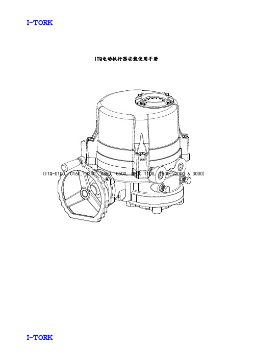
ITQ电动执行器安装使用手册(ITQ-0100, 0160, 0240, 0350, 0500, 0800 1100, 1500, 2000 & 3000)目录2.ITQ 执行器1)外部部件ITQ0100 ~ ITQ1100CAPACITOR TERMINAL BLOCKASSEMBLYMOTORTORQUE SWITCHASSEMBLYLIMIT SWITCHASSEMBLYPOTENTIOMETERASSEMBLYITQ0160 ~ ITQ1100ITQ1500 ~ ITQ30003) 参数(开关式)CAPACIT TERMINAL BLOCK ASSEMBLYMOTORITQ1500, ITQ2000 & ITQ3000ITQ0350, ITQ0500 ITQ0800, ITQ1100连接用可拆卸式驱动轴瓦3. 选型与应用VALVE BUTTERFLY BUTTERFLY 2-WAY BALL 2-WAY BALL 3-WAY BALLITQ0100 ITQ0160, 0240 ITQ0350, 0500 ITQ0800,ITQ1100 ITQ1500, ITQ2000 & ITQ3000ITQ0100 ITQ0160, ITQ0240注 : 1. 上表仅供参考,不承担任何责任!2. 应详细咨询阀门厂温度、流体特性等后再选型。
3. 特殊条件如高温、低温、海水、恶劣腐蚀性条件、高振动下的应用,在选定执行器前请咨询我们技术部门。
4. 对用户无视我们的劝告所做的决定,我们有权力回避任何责任。
人工操作向手轮方向拉动手柄,直到手柄竖直。
如果手柄未直立,再次拉,缓慢转动手轮。
在手轮上有标志指示转动方向。
顺时针为关闭方向,逆时针为打开方向。
电动运行时不必把手柄恢复原位。
ITQ0100 ITQ0160~ITQ1100 ITQ1500~ITQ30005.执行器在管道上的推荐安装1)执行器在管道上的位置10. 维修保养1)润滑因为工厂已经充分供应了润滑油,正常运行中一般不必再注入润滑油。
protel 2004使用说明

Protel 2004交互式布线模式:Ignore Obstacles(忽略障碍模式);Avoid Obstacles(避开障碍模式);Push-and-Shove(推挤障碍模式)。
Protel 2004铺铜的形式:90度角铺铜;45度角铺铜;垂直铺铜;水平铺铜。
Protel 2004内层连接:可以指定到任意的网络(Net) 。Protel 2004内层电源:所有的内层电源层都能指定到任意的网络,而且所有的内层分割都能重迭。
License文件。
二. 点击“替换密钥”,选取DXP.exe(在DXP 2004安装目录里,默认路径为C:\Program Files\Altium2004\),程序会
自动替换文件中的公开密钥。如果要使用网络版的License,还必须同时替换DXPSecurityService.exe
(在DXP 2004安装目录里,默认路径为C:\Program Files\Altium2004\)文件中的公开密钥,操作步骤同上。
(对文件修改前请手工做好备份,以防万一。)
三. 将第一步生成的License文件拷贝至DXP 2004安装目录里(默认路径为C:\Program Files\Altium2004\)
或者在DXP的使用许可管理中添加生成的License文件,网络版的License文件在
Altium DXP Security Service中添加。
V1.1 是个Debuge 版本,需要两个动态库。Release版本有毛病,正在检查原因 破解--Leabharlann 注册机:V1.2 Release版本
修正了Release版本毛病,应该不需要哪两个动态库了。
增加了密钥密钥替换时的检查,防止对其他文件的误操作。
手册大全--ln2000通讯系统手册

通讯手册1GPS授时(LN_GPS.EXE)1.1概述LK_GPS Receiver接收对时程序接收LN_GPS模块的串口对时输出,并修改操作系统时间,完成精确授时功能。
在LN2000DCS系统文件夹中,点击GPSReceiver.exe按钮,就进入LK_GPS Receiver 接收对时程序界面(如图1.1-1所示)。
图1.1-1 LN_GPS启动界面1.2程序界面说明程序显示的主体是一个对话框的形式,包括操作区、对时回显区以及对时历史区。
其中操作区是程序的设置部分,各种操作都在这里;回显区显示最近一次对时的时间、接收码以及校验对时状态;历史区显示最近100次的接收历史,包括接收码和接收时间如图1.2-1所示。
图1.2-1 LN_GPS 程序界面1.3 操作说明LK_GPS Receiver 程序主要有如下几种操作:开始接收/停止接收:此按钮操作程序是否接受来自串口的对时信号,点击开始按钮则开始接收,点击停止接收按钮则停止接收串口信号参数设置:设置程序使用的串口设置,包括选择串口号、波特率、奇偶校验等,LN_GPS 模块上信号格式采用(9600,n ,8,1)格式,即波特率为9600,没有奇偶校验、8个传输位、一个停止位。
设置好后,点击确定即可如图1.3.1所示。
图1.3.1串口设置隐藏:点击隐藏或者是最小化,程序都会隐藏窗口,在屏幕右下角工作台缩成图标,操作区 回显区历史区鼠标左键单击该图标,可还原窗口。
退出:退出程序。
清空显示:清空对时历史区显示。
1.4串口通讯接口及协议说明1.4.1 LN-GPS模块通讯接口概述LN-GPS模块对各种授时接收系统提供三种通讯接口,包括CAN接口两个,RS-485串行接口四个,RS-232串行通讯接口两个。
串行口通讯的物理层协议为RS-485与RS-232,可与任何具有RS-485或RS-232接口的计算机、设备或系统,特别是DCS系统实现通讯,通常推荐RS-485方式进行距离较远或者环境较恶劣情况下的通讯。