aeiDK-9810存储式密码键盘
華碩 GK2000 鍵盤使用手冊说明书
華碩 GK2000 鍵盤使用手冊2繁體中文T10631 第 一 版2015 年 12 月版權說明© ASUSTeK Computer Inc. All rights reserved. 華碩電腦股份有限公司保留所有權利本使用手冊包括但不限於其所包含的所有資訊皆受到著作權法之保護,未經華碩電腦股份有限公司(以下簡稱「華碩」)許可,不得任意地仿製、拷貝、謄抄、轉譯或為其他利用。
免責聲明本使用手冊是以「現況」及「以目前明示的條件下」的狀態提供給您。
在法律允許的範圍內,華碩就本使用手冊,不提供任何明示或默示的擔保及保證,包括但不限於商業適銷性、特定目的之適用性、未侵害任何他人權利及任何得使用本使用手冊或無法使用本使用手冊的保證,且華碩對因使用本使用手冊而獲取的結果或透過本使用手冊所獲得任何資訊之準確性或可靠性不提供擔保。
台端應自行承擔使用本使用手冊的所有風險。
台端明確了解並同意,華碩、華碩之授權人及其各該主管、董事、員工、代理人或關係企業皆無須為您因本使用手冊、或因使用本使用手冊、或因不可歸責於華碩的原因而無法使用本使用手冊或其任何部份而可能產生的衍生、附隨、直接、間接、特別、懲罰或任何其他損失(包括但不限於利益損失、業務中斷、資料遺失或其他金錢損失)負責,不論華碩是否被告知發生上開損失之可能性。
由於部份國家或地區可能不允許責任的全部免除或對前述損失的責任限制,所以前述限制或排除條款可能對您不適用。
台端知悉華碩有權隨時修改本使用手冊。
本產品規格或驅動程式一經改變,本使用手冊將會隨之更新。
本使用手冊更新的詳細說明請您造訪華碩的客戶服務網 /tw/support,或是直接與華碩資訊產品技術支援專線 0800-093-456 聯絡。
於本使用手冊中提及之第三人產品名稱或內容,其所有權及智慧財產權皆為各別產品或內容所有人所有且受現行智慧財產權相關法令及國際條約之保護。
當下列兩種情況發生時,本產品將不再受到華碩之保固及服務:(1) 本產品曾經過非華碩授權之維修、規格更改、零件替換或其他未經過華碩授權的行為。
fc980m说明书

fc980m说明书产品外包装采用了全新的设计风格,丰富的色彩以及抽象的线条也让键盘包装更具个性美感,同时也有着更高的外观辨识度。
包装上提供了产品展示图、产品特点介绍等内容,更加方便用户了解。
附件内容上,提供了键盘防尘罩、5枚增补键帽、塑料拔键器、两节7号电池、USB Type-C连接线以及产品说明书,附件内容还是较为丰富的。
同时,前期购买还有机会获得两枚主题键帽、钢丝拔键器以及薄荷绿的USB Type-C连接线。
外观&细节:键盘采用了LEOPOLD经典的98布局,比传统104键盘缩减了约3颗按键的长度,提供了独立的方向键区以及数字键区,保证输入效率的同时,有着更加小巧的机身尺寸,在空间占用、实用性上都有着出色表现。
键盘机身采用了灰白配色,键帽部分则为淡紫色+薄荷绿,时尚清新,浪漫柔和,能为用户带来更加自然梦幻的视觉表现。
独特的视觉风格也让外观更具辨识度。
机身表面采用了晒纹工艺处理,颗粒感较为清晰,也带来更加出色的外观质感,在观感、触感上表现都非常出色。
右上角位置则是标志性的三枚状态指示灯,指示灯为方形开孔,更加方便用户辨识。
三枚状态指示灯分别对应数字键区的开启关闭、大小写状态/蓝牙状态、Scroll Lock/电池状态。
在有线状态下,指示灯正常开启,无线状态下,除了在配对以及电量不足时会闪烁提示,其它状态下均为关闭。
侧面位置上加入了金属的LOGO标识,进一步提升了键盘整体的质感表现。
这款键盘采用了全新的外壳模具,上盖高度进行了缩减调整,可以露出更多的下底壳,为键盘带来了更加丰富的层次感,视觉观感也更加舒适自然。
键盘底部则是原有基础上加入了电源开关、蓝牙配对按钮以及电池仓,并且对DIP开关位置进行了微调。
底部采用了键线分离方案,中置USB Type-C接口,三向出线口设计,USB Type-C也提供了更好的线材兼容表现,喜欢有线的用户可以在替换线材上可以有着更加丰富的选择。
底部提供了多枚黑色防滑脚垫,确保了键盘放置稳固,不易滑动,一段式撑脚上也提供了防滑脚垫,在撑脚打开状态下也能保证键盘不会轻易产生位移。
Egardia 密码键盘安装指南说明书

installation guide Key padINSTALLATION GUIDE KEY PAD Congratulations on the purchase of your Egardia key pad. Customer Service Please visit if you would like further information about the installation and use of Egardia. The answers to a number of frequently asked questions can be found at/userquestions.This package has been put together with care. Please contact our customer service if you would like any help during installation or if something is missing from the package. Never return a package without prior instruction from our customer service.Key padThe key pad is an easy way to operate your Egardia alarm system from inside your home. Each registered user is able to turn the alarm system on or off using his/her valid PIN code. Also, the key pad allows you to partially activate your alarm system (ON, partially). This is particularly useful for e.g. safeguarding the downstairs floor while you are sleeping upstairs.When the button "HELP" is pressed a panic alarm will be triggered and all your registered contact will instantly receive an alarm message.In your Egardia account you can enter a PIN code for each authorized user. Via the tab "Alarm history" you can always see which particular user has turned the alarm system on or off.Please note! By both burglar alarms and panic alarms the gateway will emit a very constant and loud audible signal. A panic alarm can only be deactivated by the key pad. Enter a valid PIN code and press to deactivate the panic alarm.OVERVIEW KEY PAD1. Indicator light Activity (green) – The green indicator light glows for a few seconds aftera button has been pressed.2. Indicator light Transmit (red) – The red indicator light flashes a few times to indicate asignal is being sent to the gateway.3. Fault light (orange) – The orange indicator light flashes continuously when the batteriesneed replacing.4. Mounting holes – Situated under the 2 caps are the mounting holes.Key pad keys:Numerical keys (1 – 9, *, 0, #): To enter PIN codes.: Enter [PIN code] followed by to deactivate the alarm ("OFF").: Enter [PIN code] followed by to activate the alarm ("ON").: Enter [PIN code] followed by to partially activate the alarm ("ON, partially").: Press to immediately activate the panic alarm function.Website Egardia INSTALLING THE KEY PAD The installation process of the Egardia key pad consists of four easy steps.STEP 1: CHECK CONTENTS Check the contents of the packaging for the following parts: 1. Key pad (battery is factory installed in the key pad) 2. Bag containing screws and plugs 3. Velcro tapes for mounting STEP 2: ADD TO ALARM SYSTEM You are now about to register the key pad with your Egardia alarm system. 1. Remove the plastic battery tab at the back of the key pad to activate the battery. Ensure the tab has been completely removed! The green indicator light will glow and the red indicator light will flash 5 times. Wait till both indicator lights extinguish. 2. Ensure at your gateway that the alarm is turned off. The top indicator light (Status) and the bottom indicator light (Online) are lit green. 3. Press the "Reset" button at the side of the gateway for at least 5 seconds. The top indicatorlight (Status) of your gateway flashes green to indicate it is searching for new accessories.4. Press the asterisk key (*) and the hash key (#) simultaneously for at least 3 seconds. Thegateway beeps once to indicate the key pad is successfully registered. The gateway beepstwice to indicate the key pad has already been successfully registered.5. Press again the "Reset" button at the side of the gateway for at least 5 seconds if no moreaccessories are being added. The gateway returns to normal operation.6. Login to your Egardia account and go to the tab "Alarm system". The registered key pad willappear after a few minutes.7. Rename the key pad for easy recognition.STEP 3: MOUNT KEY PADPlace the key pad close to the door normally used to enter and leave the property. Before mounting use the key fob to test the desired mounting place is within range of the gateway.Important guidelinesPlace the key pad close to the main front or back door to easily operate the Egardia alarm system when leaving or entering the building.Place the key pad where it is not visible from outside.Mount the key pad at a comfortable height but out of reach for small children.Before mounting the key padremove the plastic battery tab atthe back of the key pad toactivate the battery. Theindicator lights of the key padwill now flash a few times.Instructions1. The key pad can be mounted using the Velcro tapes or by using the screws.2. For mounting with screws:a. Remove the front caps of the key pad to reveal the mounting holes.b. Use the 2 mounting holes as a template to mark the drill holes on the wall.c. Drill the holes and use the plugs for stone or plaster walls.d. Secure the key pad to the wall using the screws.e. Replace the protective caps to cover the mounting holes.STEP 4: CHECK AND TESTTo make sure that the key fob functions correctly it is advisable to test the key pad.Turn your alarm system on using the key pad. You need to press the keys of the key pad firmly. A single short beep will confirm that the keys are active. Four beeps indicate that the PIN code has not been entered correctly. If your alarm system is triggered the key pad has been installed correctly.Please note! The key pad incorporates a battery saving function. When a key is pressed the key pad will be activated for 5 seconds. In the case the key pad is not being used or the alarm had been successfully turned on or off or the time in between pressing the keys is longer than 5 seconds the indicator lights will automatically go out to increase battery life.Congratulations! The installation is complete.MAINTENANCEBatteryThe key pad is powered by one CR2450 3V 540mAH lithium button cell battery. Depending on use, the average life of the battery is 2-4 years. The key pad itself will indicate when the battery is low. When the battery has power left for about one month the orange indicator light flashes every time a key of the key pad is pressed.Replacing the battery1. Ensure that the alarm is turned off.2. Open the key pad by removing the 3 screws at the back.3. Remove the old battery. Wait 5 minutes before inserting a new CR2450 3V 540mAH lithiumbutton cell battery. Ensure that the battery polarization is correct.4. Close the key pad by replacing the 3 screws at the back.。
KPX 100可编程密码键盘指南说明书

∙∙∙∙D.A.P. Reset seePage 5∙∙∙∙∙∙∙∙∙????#*This must be done after DAP resetRecord the new code0 0 0 0*Set system into programming mode with factory set master code.8 9 0 0 8 9 0 1 # #Set system to single user mode, clear all previous data & refreshes system Set system to multi user mode, clear all previous data & refreshes system4 0 4 1 4 2 1 to 999# # # Output 1 in momentary mode from 1 to 999 seconds Output 1 in Start / Stop Mode (toggle) Output 1 in Start / Stop Mode (toggle) with accelerated code5 0 5 1 5 21 to 999 # # #Output 2 in momentary mode from 1 to 999 seconds Output 2 in Start / Stop Mode (toggle) Output 2 in Start / Stop Mode (toggle) with accelerated code0 2# # #4 digits, fixed 4 digits, fixed 4 digits, fixedPersonal Master Code & Super User CodeUser Code 1 for output 1 with Duress Code function User code 2 for output 21 Personal Master Code & Super User Code # 100 User codes in Group 1 for output 1 with Duress Code function0 1 2 00 to 99 0 to 94 to 8 digits4 to 8 digits 4 to 8 digits10 User Codes in Group 2 for output 2##i)ii)7 0 7 1 7 27 6 5 to 1000 # # ##After 10 successive false codes, keypad will lock for 30 secondsAfter 10 successive false codes, the Duress output switches to groundSelectable from 5 to 10 successive false codes, the keypad locks for 15 minutes. The keypad can be reset to release lock with the Master Code at any time during the locking period. Removal of all above security settings8 0 8 0 # #1 0Door Forced Open Alarm is Activated Door Forced Open Alarm is Disabled8 11 #1 second notification beep is given to notify the person outside to open the door when output relay is activated with a user code or egressbutton. Good for the locking device that gives no sound when it activates, such as magnetic lock. 8 1 0 #Notification beep disabled and replaced by 2 short successful code entry beeps for valid user codes.8 2 1 #Auto Entry Mode is selected. Key that followsthe user code is not required in code entry. The usercodes must be set in the same digit length as theMaster Code in Auto Entry mode and the code can be 4-8 digits82#Manual Entry Mode is selected. Key that followsthe user code is required in code entry. The user codescan be 4-8 digits and are not required to be the samelength as the Master Code.##8 3 8 3 1 0# #Tones are active on key pressTones are off. Use for silent environment requirements9 9# #No Propped Open AlarmTime from 1 to 999 seconds until door propped open activates alarm0 1 to 999*Keypad exits programming mode and returns to normal operationMASTER CODE*8 9 0 0#MASTER CODE*891#*MASTER CODE*LOCATION 1#OPTIONLOCATION n#OPTION n*0 0 0 0 * ----------- 8 9 0 0 # -----------0 3 2 8 9 1 8 3 2 1 # # --- --- 2 6 8 5 4 # ---4 0 1#Output 1 has been set to momentary mode with 1 second duration5 1 # ------------------- O utput 2 has been set to Start / Stop (toggle) mode7 21 0# ---------* ----------------------------*#8321685 4------------------ Output 1 activates for 1 secondOutput 2 Starts or Stops (toggle mode)#83 2 1 --------- Output 1 activates for 1 second 8 3 2 1--------- Output 2 Starts or Stops (toggle mode)# # 1 2 0 3 2 1--------- Duress output activates (output switches to (-) ground) & Output 1activates for 1 second8 3 #8 3 2 1--------- --------- Output 1 starts Output 1 stops3 2 8 9---------Lockout is reset and keypad resumes normal operation#0 0 0 0 --------- System is set to programming mode using factory set Master User Code * 8 9 0 1 --------- System is set to Multi-User Mode *8 (see note (a) below#0 3 2 8 -------- 3289 has been stored as the new Personal Master Code & Super User Code# 9 1 8 3 2 -------- 8321 has been stored as 1st user code in Group 1 with duresscode function# 1 0 11 3 32 --------33221 has been stored as 3rd user code in Group 1 withduress code function# 2 0 3 1 2 6 8 -------- 6854 has been stored as 1st user code in Group 2# 5 1 4 2 5 4 3 -------- 54321 has been stored as 2nduser code in Group 2#2 2 1 4 ---------------------------- Output 1 is set to Momentary Mode with 1 second duration#0 1 5 --------------------------------- Output 2 is set to Toggle Mode#1 7 ------------------------- Keypad is set to lock for 15 minutes after 10 successive falsecodes# 21 0* -----------------------------------##8 3 2 1 # ----------------------------------- Output 1 activates for 1 second1 12 1 # ------------------------------- Output 1 activates for 1 second3 3 3 2 2 # ------------------------------- Output 1 activates for 1 second1#6 8 5 4 # ----------------------------------- Output 2 Starts or Stops (toggle mode)5 4 3 2 Output 2 Starts or Stops (toggle mode)1#-------------------- 1 1 1 2 --------11223 has been stored as 2nd user code in Group 1 withduress code function# 2 0 2 3#------------------------------- 0 3 2 1 # --- Duress output activates (switches to ground) & Output 1 activates for 1 second3 1 2 2 # ---D uress output activates 9 switches to ground) & Output 1 activates for 1 second 3 5 3 2 2 # ---D uress output activates 9 switches to ground) & Output 1 activates for 1 second 18 3 #8 3 2 1 -------------------- ------------- Output 1 starts Output 1 StartsOutput 1 Stops1 1Output 1 Starts1 12 2---------Output 1 Stops3###3 2 8 9 # ------------------------------- Output 1 activates for 1 second 1 3 2 8 9# ------------------------------- Output 2 Starts or Stops (toggle mode)23 2 8 9 --------- Lockout is reset and keypad resumes normal operation#* *3 2 8 9 --------- Keypad is now in Programming Mode#1 0 5 #2 3 #*∙∙∙∙∙∙∙∙∙∙∙∙(B) DOOR SENSa) Door Auto Relock – the system willimmediately re-lock the door after a validaccess has been gained to prevent “tailgate”entry.b) Door Forced-open alarm – The keypad willgenerate an instant alarm if the door isforced to open. Enable the function withProgram Option 801c) Door Propped Open Alarm – The keypadwill generate an alarm if the door is leftopen longer than the pre-set time. Enablethe function with Program Option 9 withduration of 1 to 999 seconds.With the help of a normally closed door d) Inter-lock Control – When the door is open Position sensor (usually a magnetic door the inter-lock output of the keypad will give switch) o n the door to set up the following a (-) command to de-activate the other functions. keypad in an inter-lock system.∙∙∙∙。
美电贝尔产品-DVR键盘说明书

连接类型: 包括网络连接、RS232 地、RS485 连接,遥控连接等。用左右方向选择连接 的类型。连接的子菜单见下图菜单表。
网络连接 控点 IP 地址 控点端口 用户名称 用户密码
连接类型
RS232 连接 RS232 地址 波特率 协议 数据位
制优先级最高,255 地址的键盘控制优先级最低。
1.2.1.2 控点设置
包括 ID 号、设备类型、设备名称、连接类型等菜单设置。
ID 号:方便识别前端设备的编号。设置方式:按 ENTER 键进入 设置层,输入数值后继续按 ENTER 键返回菜单层,用户配合上下方 向移到下一个菜单项继续设置。查询方式:控制左右方向可翻查 0-255 数值。 注意:用户返回菜单层时如果输入的设备编号显示有*标志,如刚才
j
LOCK
LOCK
上锁快捷键
j
单画面监控状态时,按键循环显示云台转动和摄像
机镜头的控制菜单
辅助功能键
Fn
动态检测区域设置时,按键配合完成 录像回放时,按键可显示或隐藏回放进度条
菜单设置中需数字更改,按 FN 键,即可按相应键输
入数字
三、控制键盘接口
1、RJ45 网络接口 2、USB 接口 3、遥控发射接口 4、RS485 接口 5、RS232 口 6、电源接口 四、键盘连接和用法 1、接口特性: RS232 接口为直接接硬盘录像机用,距离不要超过 10 米。直接用 232 接口接硬盘 录像机只能接 1 台。如果控制键盘要控制超过 1 台以上的录像机,必须要用 485 口,并要 用 RS485 转 RS232 转换器进行转换。 RS-485 接口的最大传输距离标准为1200 米(9600bps 时),实际上可达3000 米,在级联模式下,RS-485 接口在总线上是容许连接多达16个键盘。 通过串口键盘最多能控制 255 台录像机。 2、连接模式: 1)通过 RS232 串口控制模式:
多功能闭路电视控制键盘ESD-CC1用户手册说明书

Multi-function CCTV control keyboardESD-CC1Users’ ManualVersion 3.0Table Of Contents1. General Introduction (4)2. Front Panel & Real Panel (5)2.1 Front Panel (5)2.2 Rear Connector Panel (6)2.3 Switch setting on rear connector PCB (6)3. Installation (7)3.1 RS485 cable (7)3.2 Cable connections (7)4. Operations (8)4.1 Power On (8)4.2 Camera Control Mode (8)4.2.1 OSD Camera Setting (9)4.2.2 Joystick (9)4.2.3 Set Preset and Run Preset (9)4.2.4 Sequence setting and execution (9)4.2.5 Auto-Pan (10)4.2.6 Cruise (11)4.2.7 Zoom/Focus Lens Control (12)4.2.8 Camera settings (All camera settings)……………………………………………12-154.3 System Setting Mode (15)4.3.1 System Linking (16)4.3.2 Set Keyboard ID (16)4.3.3 System Monitor Setting (16)4.3.4 RS-232 Baud Rate Setting (17)4.3.5 Date Setting (17)4.3.6 Time Setting (17)4.3.7 System Date/Time Correction (18)4.3.8 System Alarm List (18)4.3.9 Camera Type & Class (18)4.3.10 Key Press Beep (19)4.3.11 Alarm Reaction (19)4.3.12 Password Set (19)4.4 Multiplexer Control (19)4.5 The control and setting of Video Matrix Switcher (19)5. Troubleshooting (20)Appendix A. RS485 Communication (21)A.1 Connector (RJ-11 6P6C) (21)A.2 ID Address Mapping (21)Appendix B. Technical Specifications (22)Appendix C. The Architecture of SuperMPX and SuperMMX.......................................23-24 Appendix D. Commands Tree of Operating and Setting...............................................25-26 Appendix E. Software upgrade. (27)1. General IntroductionThis control keyboard is 100% integrated with our full range CCTV series, or other products that are compatible with the DSCP protocol. Equipped with the most sophisticated control protocols, this high-tech keyboard will greatly enhance the efficiency of the overall CCTV system. It also effectively integrates our Triplex Multiplexer, High Speed Dome Camera and other CCTV devices into one powerful yet user-friendly solution.Developed with the most advance data communication protocol-DSCP, this control keyboard is able to automatically detect peripheral devices for their model and capability. Together with advanced system integrating technology and user-friendly design, it provides real-time operating environment for monitoring and controlling in a multiple devices surveillance system.42. Front Panel & Real Panel2.1 Front panel1. Multiplexer mode.2. Matrix mode.(Reserved)3. Camera/Dome mode.4. System Setup key.5. Camera Function keys and Direction keys.6. Camera Menu key /Enter key: in Camera Control mode, press for 2 seconds will get OSD menu. In Camera Setup mode it functions as Enter key.7. LCD panel: display system status and set up dialogue. In power saving mode, the LCD backlight will be temporarily turned off (50% power saved). Simply press any key to exit power saving mode.8. Keyboard Lock (keep pressing for 3 seconds to lock/unlock the keyboard).9. Joystick10. Multiplexer or Matrix control keys.11. VCR remote keys with blue.12. Home key.13. Number keys and ENTER key.14. Function key. F1 is remote-reset function. F2 is lock/unlock device function. F3 is reservedcurrently. F4 is Dome speed test function.15.Lens control keys.16.Sequence setting keys including INS/DEL/ENDSEQ keys.S4 RS232 Control N ▓ V Normal (Default, DTR/DSR function) N ▓ V VCR control (RTS/CTS function)3. InstallationMonitor• Dome/CameraConnect the RS-485 cables from cameras to keyboard. And connect the video cables to monitor or multiplexer.(Caution! The ID address and video channel connection (of multiplexer) must follow the definition in Appendix A!)• Video MultiplexerConnect RS-485 to the keyboard directly or loop through the cameras.74. Operations4.1 Power OnAfter connecting all necessary cables, turn on the peripheral devices, and then connect DC12V adapter to the keyboard. The LCD will display the following message:Later, the keyboard will enter ‘Stand By Mode ’.Stand By Mode:In the 'Stand By Mode', user can enter ‘System Setting Mode ’ by pressing “SYS” key (section 3.4), or enter ‘CameraControl Mode ’ by pressing Camera Select key (section 3.5), or enter ‘Multiplexer Control Mode ’ by pressing Multiplexer Select key (section 3.6), or enter ‘Matrix Control Mode ’ by pressing Matrix Select key MX (section 3.7).4.2 Camera Control ModeWhen the keyboard is in Stand By Mode , you can select any active camera by pressing Camera Select key, number key "1"~"223" and then “ENTER” key or press # + 1(~9) to choose the index X camera of class X . The ID and device type of the selected camera will be displayed on LCD. P=Pan, T=Tilt, Z=Zoom, F=Focus, OSD=OSD available.Now the keyboard is in Camera Control Mode , you can control all of the camera’s functions in this mode.8Camera Control Mode:The second row on the LCD allows users to input number 1~255, it’s used to specify preset point or the other cameraparameters. Detail operation will be described in the following sections. Please refer to camera’s manual to understand the function of each camera. 4.2.1 OSD camera settingIf the camera selected is equipped with OSD function, you can press “CAMERA MENU” key to get the OSD menu on the monitor. Then you can use the four direction keys to setup the parameters of the camera. 4.2.2 JoystickThe joystick is used to control Speed Dome Camera viewpoint (Pan/Tilt position). Normally, the Speed Dome Camera supports hemispheric viewpoints (Pan 360° and Tilt 90°). The speed of the dome movement depends on the angel of the Joystick, the more you push the Joystick, the faster the dome will move. The maximum speed when using Joystick is limited to get better control of the dome camera, there are 7 different speeds available. 4.2.3 Set Preset and Run PresetUnder the Camera Control Mode , you can key in a number (1~128) and press “SET PRESET” key, the keyboard will ask the dome to store current position as a ‘Preset’. You may also key in the number and press “GO PRESET” key to ask the dome to move to that specific preset point.Camera Control Mode4.2.4 Sequence setting and executionThe dome camera allows you to program up to four sequences, each sequence contains 32 steps. When the keyboard is under the Camera Control Mode , you may input number 1~ 4, and press “RUN SEQ” key. The dome will start touring that sequence, and show the following message on the LCD for a few seconds:You can also input number 1~ 4 and press "SET SEQ" key to edit the sequence contents. You may use "▲"/"▼" keys to scroll through all 32 steps, and use "◄"/"►" keys to move the cursor to the items you want to edit.9A. The first three digit (xxx) indicate the step number.B. PST means ‘Preset Point’, it is the preset point used for this step, range from 1 to 128.C. SPD means ‘Speed’, it defines how fast the dome will move from previous step to this step, the number range from1 to 15.D. DWELL means the dwell time of this step. The number range from 1 to 127, and the unit is second.If you want to insert a step in the sequence, you can press “INS” key, then key in the parameters in current position. If you want to delete a step in the sequence, just press “DEL” key, current step will be erased immediately.After sequence editing is finished, you may use “ESC” or "ENDSEQ" keys to exit. The difference between these two keys is: pressing “ENDSEQ” will delete the steps behind current step; pressing “ESC” will keep every step effective. 4.2.5 Auto-PanUnder Camera Control Mode , you can press “AUTOPAN” key to enter Auto Pan mode , the LCD will display:Auto Pan mode:Press "1", the dome start to pan automatically, and the LCD will display:Press "2" allows you to edit the route of auto-pan. You have to move the dome to the start point, and press “Enter” key to confirm.Then move the dome to the end point and press “Enter” key to confirm.10And then you have to decide the pan direction and the pan speed:4.2.6 CruiseUnder Camera Control Mode , you can press “CRUISE” key to enter Cruise mode , the LCD will display:Cruise mode:Press "1", the dome starts to cruise automatically, and the LCD will display:Press "2" allows you to edit the route of cruise. You have to move the dome to the start point, and press “Select Device/ Enter” key to confirm.11Then move the dome to the end point and press “Select Device/ Enter” key to confirm.And then you have to press “Select Device/ Enter” key to save it.4.2.7 Zoom/Focus Lens controlIn the ‘Camera Control mode ’, you can control the lens using the ‘Lens Control Keys’ on the right hand side of the keyboard. These function keys include Zoom Wide/Tele, Focus Near/Far and Iris Open/Close and Auto Focus hot key.4.2.8 Camera settingPressing ”SETUP” key in Camera Control Mode will enter Camera Setting Mode , you can setup many features of the camera here. You have to key in the password first:Camera Setting ModeAfter you key in the correct password, you can use the "▲"/"▼" keys to scroll through these setup pages, and use "◄"/"►" keys to change the setting. Use “ESC” key to exit after the configuration is finished.4.2.8.1 Auto Turn-AroundThe Auto Turn-Around function is useful for following a person who passes directly beneath the camera, the dome rotates 180 degrees if you keep holding the joystick. Menu 2.1 allows you to enable or disable this function.Fig.4.2.6.5124.2.8.2 Zoom speed settingThis item allows you to change the speed of zoom lens movement, use "◄"/"►" keys to select Slow or Fast speed.4.2.8.3 Digital Zoom ratioThis item allows you to change the digital zoom ratio from OFF (no digital magnify) to 8X (8 times digital magnify).4.2.8.4 Alarm SetupThe dome camera is equipped with four alarm input connectors, Alarm1~Alarm4. Once the alarm signal is detected, the dome camera will move to a preset viewpoint automatically. Menu 2.4 allows you to decide how the dome will react to the alarm inputs.Menu 2.4.1 decide how long the dome camera will stay in the alarm preset. This parameter is common for all the four alarm inputs.13Menu 2.4.2 is the entry point for parameters related to Alarm1 input: ON/OFF (detect alarm signal or not), NC/NO (alarm signal type) and correspondent preset point for each Alarm input:4.2.8.5 Speed by ZoomWhen the lens is in Tele position, the pan/tilt speed is better slowed down to allow the user to trace the target smoothly. If you select ON here, the Pan/Tilt movement of the Dome will be proportional to the zoom ratio.4.2.8.6 Set PAN bias144.2.8.7 Set TILT bias4.2.8.8 Check Camera VersionThis item shows you the hardware and software version of the dome camera, it may be an useful information when you’re checking with the installer for trouble shooting.4.2.8.9 Auto Save Function.The user can disable or specify the duration time of 1~42 minutes to make a power-up default preset point for dome camera to go back after the operator stops moving the dome.4.2.8.10 Line Lock Phase Adjust Function.User should not use this function for detailed adjustment of camera module.4.2.8.11 Receiver Auxiliary Switch Function.Users can press 1 or 2 to select one of two receiver auxiliary switches and then press "◄" / "►" key to turn on/off receiver auxiliary switch.4.3 System Setting ModeIf you press the “SYS” key and enter the correct password (default password is 0000), the keyboard will enter ‘System Setting Mode ’. Detail description of each item will be discussed in the following sections. Please use "▲" and "▼" keys to scroll through these setup pages.15System Setting Mode:4.3.1 System LinkingMenu 1.1 allow you to search for active cameras on the RS485 control bus again, press "◄" or "►" key to start searching.4.3.2 Set Keyboard IDMenu 1.2 allow you to set up the ID number of this keyboard, use "◄" or "►" key to change the number. The default ID is 000, if there are more than one keyboard in the same system, they must have different ID address to avoid communication conflict.4.3.3 System monitor settingWhen you use the keyboard to control devices, it needs Monitor to see the image to prevent wrong actions. There are four sources you can select, the first one is Multiplexer’s main monitor output, the second one is Matrix’s output, the third one is the SuperMPX mode, and the last one is SuperMMX mode.When you select Item a.(as Fig.4.3.3.1), the image of camera will be displayed on Multiplexer’s main monitor. On the other hand, when select Item b. (as Fig.4.3.3.2 and hit “ENTER”), please input the Output Channel/Monitor no. (as Fig.4.3.3.5) and hit “ENTER” key. The image of camera will be displayed on Matrix’s monitor. Hit “ESC” to go back System mode.Please refer Appendix C to see the architecture of SuperMPX and SuperMMX.164.3.4 RS-232 Baud rate settingTo select Item 4 (as Fig.4.3.4.1) and you can set RS232 Baud rate. The RS-232 protocol of keyboard is the standard 8,N,1. It provides three Baud rate setting (9600 (default), 4800 and 2400 bps). It can be set on your request (as Fig.4.3.4.1,4.3.4.2, 4.3.4.3). Hit "◄"/"►" key to select baud rate and hit “ENTER” key). Hit “ESC” to go back System mode.4.3.5 Date SettingSelect Item 5(as Fig.4.3.5.1) and hit “ENTER” key (as Fig.4.3.5.2), then you can set the correct date of keyboard. Please hit "◄"/"►" key to select items (year, month and date) and input the correct numbers. The default date is local. Hit “ESC” to go back System mode.4.3.6 Time SettingSelect Item 5(as Fig.4.3.6.1) and hit “ENTER” key (as Fig.4.3.6.2), then you can set the correct time of keyboard. Please hit "◄"/"►" key to select items (hour, minute and second) and input the correct numbers. The default date is local. Hit “ESC” to go back System mode.174.3.7 System Date/Time CorrectionSelect Item 8(as Fig.4.3.7.1) and hit “ENTER” key (as Fig.4.3.7.2), then you can adjust all the devices at same time. Before you adjust the system date/time. Please check the date/time of this keyboard and make sure it’s correct. Hit “ESC” to go back System mode.4.3.8 System Alarm ListRecord the latest 10 Alarm information of the system bus.4.3.9 Camera Type & ClassThis item allows you to assign protocol type for each camera in current group number. Use "◄" or "►" key to change the setting , “▲” or “▼” key to choose the index and “AUTOPAN” or “CRUISE” key to choose the class.184.3.10 Key Press BeepThe built-in buzzer will beep when the user press any valid key, this item allow you to turn the beep on or off. Use "◄" or "►" key to change the setting.4.3.11 Alarm ReactionWhen the alarm input of the dome camera is triggered, the camera will send an alarm message to the keyboard. The keyboard can be programmed to react to the message by: 1. Buzzer beep, 2. link to that camera automatically (so operator can control that camera immediately), 3. switch the multiplexer to that channel in full screen.These reactions are disabled (OFF) by default. Menu 1.5 allows you to enable (ON) this function. Use "◄" or "►" key to change the setting.4.3.12 Password SetThis item allows you to change the password, you have to enter the same number twice to confirm the change.4.4 Multiplexer Control Under any mode, hit Multiplexer control key and input the Multiplexer’s number then hit “ENTER” key (as Fig.4.4.1). Then, you can remotely control that particular Multiplexer. Please refer Multiplexer’s manual to get the method of control and setting.4.5 The control and setting of Video Matrix SwitcherIt is reserved now.Under any mode, you can hit “Matrix” hot key to remote control the video matrix switcher. You can hit “ENTER” key to enter OSD control mode. You can hit “Direction”, “ENTER” and “ESC” keys to set all programs of Matrix. Please reference the Matrix’s manual to get the detail definition of Matrix.195. TroubleshootingWhen you get trouble with using the keyboard, please follow the procedures below to isolate the problem before call back to the installer.A. Nothing or wrong text is displayed on LCD.Possible causes and countermeasures:a. No power or unstable power source: check the output of the DC12V adapter is correct or not.b. Interference comes from peripheral devices: disconnect the RS-485/422 and RS-232 connectors and re-start thekeyboard. If the keyboard works fine now, then we can conclude some of the other device cause the trouble, please connect the installer to solve the problem.B. Device Link-up problemPossible cause and treatment:a. The keyboard RS-485 cable connection is not secure: please make sure the cable is firmly connected on both thekeyboard side and device side.b. Wrong start-up procedure: some peripheral devices (as P/T/Z/F dome cameras) need longer initial time afterpower on. They can not recognize the linking command during the initial time. Please make sure that all the peripheral devices have been powered-up before applying power on the keyboard.c. RS-485 cable open or short: please separate each device and find out which segment of the communication youcan connect single keyboard and device to confirm this possible cause. Please connect the concerning people and tell them this test result.C. One or some devices lose controlPossible cause and treatment:a. The bus does not connect to those peripheral devices: please check the RS-485 cables on those peripheral sidesand make sure those cables are connected perfectly.b. Malfunction of the peripheral devices: you can connect one keyboard to one device to confirm the properfunctioning of the device.c. One of the RS-485 cable segments open or short circuit: disconnect the cable segment and locate the failuresegment. Please connect the installer for support.20B. Multiplexer (MPX) Channels and Camera ID MappingMPX # MPX ID Camera ID Remark1 E0H,224 01H – 10H\ 1~16 Map to channel 1~16 of MPX2 E1H,225 11H – 20H\ 17~323 E2H,226 21H – 30H\ 33~484 E3H,227 31H – 40H\ 49~645 E4H,228 41H – 50H\ 65~806 E5H,229 51H – 60H\ 81~967 E6H,230 61H – 70H\ 97~1128 E7H,231 71H – 80H\ 113~1289 E8H,232 81H – 90H\ 129~14410 E9H,233 91H – A0H\ 145~16011 EAH,234 A1H – B0H\ 161~17612 EBH,235 B1H – C0H\ 177~19213 ECH,236 C1H – D0H\ 193~20814 EDH,237 D0H – DFH\ 209~223 Only 15 Dome can be connect15 EEH,238 None Can connect to normal camera16 EFH,239 None Can connect to normal camera21Appendix B. Technical SpecificationsThe list is the specifications of CCTV control keyboard, our company reserve the right to modify the specifications.Item DescriptionCameraSpeed Dome Camera all functionSystem ControlOSD Camera all functionZoom Lens Camera all functionVideo Multiplexer All functionVideo Matrix (reserved)Linking capability 255 Devices(Maximum)RS232Signal RS485(half-duplex),ConnectorsPower DC Jack, and terminal blockRS-485 RJ-11*2 (6P6C), and terminal blockRS-232 9pin D-sub, malePower SupplyInput Voltage 12VDC(-15/+50%)Power Consumption 5WSafety Approval CE,FCCDimensionWidth 300mmHeight 65mmDepth 175mmEnvironmentalOperation Temperature 0℃ ~ 40℃Humidity 10%~90% RH, Non-condensationStorage Temperature -10℃~60℃22Appendix C. The Architecture of SuperMPX and SuperMMXC.1 SuperMPX modeDOME ID#1 #2 #3 …… #16 #17 #18 ..…. #32 …. #208 ……. #22323C.2 SuperMMX modeDOME ID#1 #2 #3 …. #16 #17 #18 …. #32 …. #208 ……. #22324Appendix D. Commands Tree of Operating and SettingSystemcontrol + 1 ~ 223 Joystick PAN/TILTSelect CameraControlLensZOOM WIDE Zoom WideZOOM TELE Zoom TeleFOCUS NEAR Focus nearFOCUS FAR Focus farAUTO/FOCUS Auto-focus/Manual-focusBRIGHTNESS - Brightness downBRIGHTNESS + Brightness up1 ~ 128 GO PRESET Go to Preset point #SET PRESET Save to Preset point #1 ~ 4 RUN SEQ Play Sequence #SET SEQ Edit Sequence #AUTOPAN 1 Play Autopan2 Set AutopanCAMERA MEMU Use direction keys and see OSD to controlkey LOCK/UNLOCK Lock/UnlockSETUP 1. Auto Turn-Around Use ◄► key to turn on/offEnter password 2. Zoom Speed Use ◄► key to turn fast/slow3. Digital Zoom Use ◄► key to turn x1/x2/x4/x84. Alarm Set Set on/off, NC/NO and Preset5. Speed by Zoom PAN/TILT speed by Zoom Ratio6. Set PAN bias Set Dome's PAN bias, -5~+57. Set TILT bias Set Dome's TILT bias, -5~+58. Camera Version Show Camera's version+ 1 ~ 16 Function keys Please refer Multiplexer ManualSelect Multiplexer 1 ~ 16 ENTER Change Display Channel25SYS Enter password 1. System Linking Scan the exist deviceSystem Setup 2. Set Keyboard ID Keyboard ID Setting 0,240-2543. System Monitor MPX,MTX,SuperMPX,SuperMMX4. RS232 Baud-rate set Use ◄► key to select 2400/4800/96005. Date setting Set Date: year, month, day6. Time setting Set Time: hour, minute, second7. System T/D correction System Time/Date correction8. System Alarm List Record the latest 10 Alarm information9. RS232/485 mode Use ◄► key to select RS232/485 mode10. Key Press Beep Use ◄► key to turn on/off11. Alarm Reaction Use ◄► key to turn on/off12. Password Set new passwordAppendix E. Software upgradeThe system installer can use a Personal Computer to download the upgrade software to the keyboard via RS-232 port. The download procedure is described below:Warning! This operation is available for system installers only.Step 1 E xecute the Auto-unpack.exe on the computerThe program will create a sub-directory called “Keyboard” and unpack three files in thedirectory: Keyboard.exe, Keyboard.tsk and Readme.doc.Please read the Readme.doc carefully before going on the download process.Step 2 C onnect the RS-232 cablePlease use a 9 pin one-by-one cable to connect the keyboard to the computer, and find outwhich communication port (COM1 or COM2) is used.Step 3 C heck S2 switch setting on the rear boardRefer to section 2.3 and make sure S2 (RS-232 setting) is on “S” (slave) position.Step 4 K eep pressing “SETUP” key, and then power on the keyboardThe LCD will display “Ready to Download” message.Step 5 E xecute Keyboard.exe on the computerThe download process will start after you select the correct COM port number. It takesone or two minutes to finish. Please power off and on the keyboard after the downloadprocess is finished.27。
DS-PK1-E-WB 无线LED数字键盘用户手册说明书
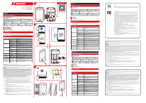
Wireless LED KeypadUser Manual561. IndicatorInstallationAppearanceEnrollmentSpecificationUser ManualUser Manual3. Serial PortDS-PK1-E-WBScan the QR code for more information and operation help.3Check signal strength.1236. Interruptor de alimentación1. Piloto5. Botón MANIPULACIÓNInstalaciónEspañolDiagrama de referenciaAparienciaRegistro4. BateríaManual de usuario3. Puerto serieEscanee el código QR para obtener más información y ayuda sobre elComprobar la intensidad de la señal.1231. IndicadorInstalaçãoPortuguêsReferências do diagramaApresentaçãoRegistroManual do usuário3. Porta serialVerificar a intensidade do sinal.123WarningThis is a class A product. In a domestic environment this product may cause radiointer-ference in which case the user may be required to take adequate measures.FCC InformationPlease take attention that changes or modification not expressly approved bythe party responsible for compliance could void the user’s authority to operatethe equipment.FCC compliance: This equipment has been tested and found to comply with thelimits for a Class B digital device, pursuant to part 15 of the FCC Rules. Theselimits are designed to provide reasonable protection against harmfulinterference in a residential installation. This equipment generates, uses andcan radiate radio frequency energy and, if not installed and used in accordancewith the instructions, may cause harmful interference to radio communications.However, there is no guarantee that interference will not occur in a particularinstallation. If this equipment does cause harmful interference to radio ortelevision reception, which can be determined by turning the equipment offand on, the user is encouraged to try to correct the interference by one or moreof the following measures:—Reorient or relocate the receiving antenna.—Increase the separation between the equipment and receiver.—Connect the equipment into an outlet on a circuit different from that towhich the receiver is connected.—Consult the dealer or an experienced radio/TV technician for help.This equipment should be installed and operated with a minimum distance20cm between the radiator and your body.FCC ConditionsThis device complies with part 15 of the FCC Rules. Operation is subject to thefollowing two conditions:1. This device may not cause harmful interference.2. This device must accept any interference received, including interference thatmay cause undesired operation。
Rapoo E9070 无线超薄键盘 快速入门指南说明书

备注:请将各条填写清楚,请勿擅自涂改,并妥善保管好本保修服务卡,以维护您的合法权益。
如需服务或有任何疑问, 请咨询当地经销商或与我们联系。
USBE9070Wireless Ultra-Slim KeyboardQuick Start Guide (V1.1)M/N :Rating: Approval No: CMIIT ID:M/N : Rating: Approval No: CMIIT ID:5602-04D00-222WarrantyThe device is provided with one-year limited hardware warranty from the purchase day. Please see /warranty for more information.See /E9070/faq for latest FAQs, drivers and quick start guide. For extensive service, register at /register.TroubleshootingDo not open or repair this device. Do not use the device in a damp environment. Clean the device with a dry cloth.Safety instructionsCopyrightIt is forbidden to reproduce any part of this quick start guide without the permission of Rapoo Technology Co., Ltd.质保条款本設備提供自購買之日起1年的有限產品硬體保固服務,具體詳情請查閱/warranty。
請到/E9070/faq查閱最新常見問題、請到/E9070/download下載最新的驅動和快速安裝指南。
雲端 加密键盘 OK10 说明书

oTHE Technology Inc.
6
雲端加密鍵盤 使用手冊
2.3 Program, Class of Active Window
oTHE Technology Inc.
這裡將會顯示您目前所使用的應用軟體的 Program Name 和 Class Name。 「Support This Now」按鈕若顯示不能點選 時,代表這個應用軟體已經在 OK100 支援保 護的名單中。
雲端加密鍵使用 Windows 內建標準驅動程式。Windows 會告訴您驅動程
式的安裝過程與結果,如果一切正常,第一次安裝硬體,約數秒鐘後,您便
可以正常使用沒有保護功能的標準鍵盤。
4. 若步驟 3 沒有成功,請再次確認步驟 1~3 是否確實都連接好。若 1~3 都正
常安裝還未能正常使用標準鍵盤,有可能您的鍵盤與 OK100 不相容,請您
2.2.3 Keylogger Bar On Top:設定 Keylogger Bar 為最上層顯示。當 您沒有輸入文字超過 5 秒鐘,Keylogger Bar 會暫時隱藏。
2.2.4 Keylogger Bar On Title:設定 Keylogger Bar 顯示於使用中的應 用程式標題上。
2.2.5 Auto Run After Reboot:設定 OK100 主程式於每次電腦重新啟 動時自動執行。
2.2.6 Vision Signal In Text Window When Active:設定 Vision Signal 功能。當 Vision Signal 功能開啟時,OK100 安全模式支援下的文 字輸入框中會顯示 OK100 的圖示,提醒您 OK100 保護模式正在 保護您所輸入的文字。(此功能預設為關閉)
ESIK专用键盘技术说明书

ESK1型专用键盘技术说明书北京东方仿真技术研究所一九九八年六月ESK1型专用键盘技术说明书ESK1型专用键盘是一个单片微机系统,它可以支持256键输入和128个指示灯显示。
该专用键盘可以通过串行接口与PC机联接,用户可在DOS环境或Windows环境中调用驻留的接口程序模块,以获取键值或设置、修改灯态。
该专用键盘不仅可以获取单个键按下的键值,而且可以获得多个键同时按下的组合键值。
该专用键盘内部设有watch dog电路,运行可靠,抗干扰能力强。
该专用键盘通过一块随机提供的转接卡与PC机联接,这块转接卡插至PC机插槽内。
联接如图1所示。
┌──────────────┐\par│PC机││││┌───┐┌───┐│││转接卡││串行口││└─┴┬─┬┴──┴─┬─┴─┘专│││用│└─────┘键│串口联接电缆盘│联│接│电│缆│┌──┴──┐│ESK1型││专用键盘│└─────┘图1一、接口程序模块的驻留方法运行随机软盘中的wkb.exe文件,可将接口程序模块驻留在PC机的内存中。
用户可运行该文件,并在命令行参数中指明使用的串口号。
例如用户选用串口2联接专用键盘则可键入 wkb 2,以驻留该接口程序模块。
须注意的的是驻留该接口程序模块应在DOS环境中进行,即使用户要在windows环境中调用该接口程序模块,也必须在windows装入之前先在DOS环境下驻留该接口程序模块,否则将引起驻留失败。
二、接口程序模块调用方法:不论是在DOS环境还是在windows环境均可通过软中断E0H来实现接口程序模块的调用。
1、初始化模块寄存器DI低字节为命令寄存器。
令DI低字为2,调软中断E0H 则可完成初始化。
须注意初始化应在专用键盘应用环境建立后再调用。
例如用户要在widows环境中应用专用键盘,则应在windows装入之后再进行专用键盘初始化。
2、获取键值模块令命令寄存器DI低字节为1,调用软中断E0H,则可获取专用键盘的键值。
密码小键盘-深圳市智励电子有限公司文档

ZLE900系列密码小键盘使用说明书ZLE深圳市智励电子有限公司一、产品简介ZLE900系列密码键盘有15个长寿命按键,色彩高雅,外观漂亮。
通常作为计算机的外部设备,供输入交易代码、帐号及用户密码使用,广泛用于银行、邮政储蓄和证券交易的领域中,采用键盘仿真接口或串行通讯接口,可联接PC机或终端上使用。
二、技术参数:电源:DC+5V功耗:<200Mw重量:<200克按键:F1,F2,F3,0-9,“确认”,“清除”共15个按键三、型号说明:ZLE90口:接口为键盘口(用控制器来进行PC/终端键盘和密码键盘间的切换)ZLE90口K:接口为键盘口(没有控制器,用PC/终端键盘中的组合键来控制密码键盘的打开或关闭)ZLE90口S:接口为键盘口(没有控制器,用系统软件控制密码键盘的工作控制,常接终端的键盘铺口)ZLE90口R(D):接口为串口型,电平为RS232ZLE90口R(D):接口为串口型,电平为TTL注:串口型密码键盘除接口区别上,另有命令区别,详细需另见产品的软件版本号,型号中如有Z(D)表示该产品可增加DES加密法。
其中口包含意义如下:口 1 基本型2 语音提示3 液晶提示4 语音+液晶提示例:ZLE902K:为键盘方式接口,用PC键盘控制,语音提示。
四、联接示意图:1、ZLE90口密码键盘2、ZLE90口K密码键盘3、ZLE90口S 密码键盘4、ZLE90口R/ZLE90口RT 密码键盘连接PC 机或无+5V 电源输出的终端口五、键码:1、键盘口方式ZLE90口型/ZLE90口K 型/ZLE90口S 型密码键盘。
键位 定义0-9 数字0-9确定 同PC 键盘ENTER清除 同PC 键盘DEL2、串口通讯方式ZLE90口RT型密码键盘。
按键键值(ASCII字符)0 30H1 31H2 32H3 33H4 34H5 35H6 36H7 37H8 38H9 39H确认0DH清除08H注:依据用户的要求可以设定不同的键值。
智能门锁密码键盘的安装说明

智能门锁密码键盘的安装说明智能门锁密码键盘的安装说明智能门锁密码键盘已经成为现代家庭和办公场所的必备设备。
它为我们提供了方便、安全和智能化的门禁管理解决方案。
本文将为您介绍如何正确安装智能门锁密码键盘,以及一些建议和注意事项。
1. 准备工作在安装之前,确保准备充足的工具和材料。
常用的安装工具包括螺丝刀、扳手、电钻等。
此外,还需要根据门锁类型准备合适的安装配件,如螺丝、螺栓、胶水等。
2. 确定安装位置在安装智能门锁密码键盘之前,先确定好合适的安装位置。
一般来说,安装位置应该在门的内侧,高度适中,方便使用,同时也不容易被外部人员看到。
选择一个结实的门框位置以确保安全性。
3. 进行实际安装根据门锁型号和说明书提供的指导,开始实际的安装过程。
首先,使用合适的工具将密码键盘固定在门上,确保它紧密地安装在合适的位置。
接着,根据说明书上的示意图,安装其他的组件和配件,如电池、连接线等。
如果需要接通电源线,确保电源线通过安全合理的位置。
4. 连接设备和设置密码安装完毕后,连接密码键盘到智能门锁控制中心或其他主设备。
然后,根据说明书上的步骤,设置管理员密码和其他用户密码,确保每个用户都能得到正确的权限。
在设置密码时,请务必选择强密码,避免使用简单的、容易猜测的密码。
5. 进行测试安装完成后,进行功能测试以确保一切正常工作。
首先,尝试使用已设置的管理员密码打开门锁。
然后,为其他用户设置密码,让他们分别尝试使用密码开启门锁。
确保所有密码都能得到正确的响应,并且门锁能够稳定工作。
6. 设置其他功能某些智能门锁密码键盘还具有其他功能,如指纹识别、远程控制等。
根据说明书的指导,可以相应地设置这些功能。
确保按照正确的步骤和顺序进行设置,以免造成功能异常或无法使用。
7. 维护和保养完成安装后,需要定期进行维护和保养。
请务必按照说明书中的建议,清洁和保养密码键盘及门锁。
定期更换电池,以确保门锁正常运行。
同时,定期检查和紧固各个组件,以防止松动和故障。
金融行业密码键盘使用说明书

金融行业密码键盘使用说明书使用说明书一、产品概述密码键盘是金融行业中一种重要的安全设备,用于在金融交易中输入密码。
本使用说明书将详细介绍密码键盘的功能、特点以及正确的使用方法,以帮助用户充分发挥该设备的作用,确保交易过程的安全性。
二、产品功能1. 密码输入:密码键盘具备快速、准确的密码输入功能,支持数字、字母和符号的组合输入,以满足不同系统的密码要求。
2. 加密传输:密码键盘采用高级加密算法,确保用户输入的密码在传输过程中不被窃取或篡改,保护用户的账户安全。
3. 防窃听设计:密码键盘内置窃听防护装置,有效防止恶意程序或设备通过窃听技术获取用户的密码信息。
4. 用户认证:密码键盘支持用户指纹、声纹和虹膜等生物特征识别技术,进一步提高用户身份验证的安全性。
5. 兼容性强:密码键盘兼容多种操作系统和接口,可与主流的银行系统和ATM设备无缝集成,便于用户实现多样化的金融操作需求。
三、安装与配置1. 解包验货:打开包装箱,逐一核对密码键盘及相关附件是否完好,并保留购买凭证。
2. 连接设备:将密码键盘通过USB接口或其他适配器连接至计算机或终端设备,确保连接端口稳定可靠。
3. 驱动安装:根据操作系统提示,进行密码键盘驱动程序的安装,确保设备能够正常被系统识别和使用。
4. 参数配置:根据实际需求,进入系统设置界面,对密码键盘进行相关参数的配置,包括密码长度、键盘灵敏度、声音提示等,以满足个性化的使用需求。
四、使用方法1. 准备工作:确保密码键盘与终端设备正常连接,并开启相关金融系统或应用程序。
2. 密码输入:根据系统提示,在密码输入界面正确输入密码,注意遮挡输入过程,以防他人偷窥密码。
3. 身份验证:根据系统要求,进行用户身份验证,如指纹或声纹等,确保只有合法用户可以进行交易操作。
4. 密码修改:如需修改密码,根据系统设置进入密码修改界面,按照规定的流程进行密码的重设,确保密码的安全性。
5. 维护保养:定期清洁密码键盘表面,避免灰尘或污渍进入键盘影响正常使用,注意避免使用含有酸碱性物质的清洁剂。
iPazzPort迷你射频USB 红外多功能键盘遥控 KP-810-61(背光版)说明书

User manual迷你射频USB/红外多功能键盘遥控KP-810-61(背光版)Email:*********************Video tutorial on YouTube: iPazzPortfan搜索发邮件il21.4规格:- 无线连接- 最大距离:10米- 尺寸:142.5X97X19.8mm - 重量:121克- 工作电压:3.3V- 电源:可充电锂离子电池1.5系统要求:- Windows - 苹果系统- Linux- Android / Google /智能电视1基本信息:1.1使用范围:- 用于家庭娱乐的迷你视频 /红外背光键盘,教育,培训,会议,演讲和投影仪-Windows ,Mac ,Android /谷歌,Linux ,- 电脑,智能电视,树莓派,电视盒,机顶盒1.2 特点:- 8个IR学习功能的独家按钮;- 微型,便于携带;- 多个手势识别和滚动条;- 带USB接收器的无线射频,即插即用;- QWERTY全键盘布局;- 多语言版本(需要定制);- 背光,方便在昏暗的房间内操作;- 采用锂离子电池供电,超长待机。
1.3包装:- 迷你键盘1- 用户手册1- USB线12 .使用说明2.1连接和启动1)打开后盖,取出USB 接收器2)将USB 接收器插入主机的USB 插孔 比如 树莓派,(智能)电视/智 能播放器,电脑等)接收器开关3)将开关推到 "On”的位置打开键盘(指示灯会亮,然后熄灭)4成功后,用手在触摸板上滑动,可以看到鼠标随着移动) 无线连接自动完成3.2.3.键盘充电:没有任何操,键盘总是闪烁,这意味着你的键盘键盘功耗很低。
请将USB 电缆的微端连接到键盘并为其充电 另一端是电脑。
(它会点亮并稳定亮起,然后在充满电时熄灭。
42.2射频连接:通常,键盘和USB 接收器在工厂已经完成配对,你只需将USB 加密狗插入你的电脑,电视盒等的USB 端口即可使用,但如果电脑已经识别USB 接收器,但你在键盘上按按键或在触摸板上滑动都不能移动屏幕上的光标的话,就需要重新连接键盘和接收器.(1)将键盘靠近接收器,然后按住按钮Fn ,然后按下RF 。
ok100云端键盘加密串接器 说明书v1.24

OK100云端键盘加密串接器使用手册v.1.24目录1.产品简介 (3)2.硬件安装步骤 (4)3.软件安装步骤 (5)4.OK100软件基本功能 (8)5.OK100软件进阶使用说明 (10)5.1OK100 选单说明 (10)5.2OK100设定窗口说明 (11)5.3OK100支持列表 (13)5.4软件限制 (16)5.5软件卸载 (16)6.键盘按键编码与输入法 (17)6.1键盘按键编码 (17)6.2东亚语系输入法 (17)1. 产品简介OK100云端键盘加密串接器是一个键盘加密系统,它内建奥乐科技(oTHE Technology Inc.)的键盘加密芯片,只要是有进行键盘输入的时候,如重要文件、账号密码等等的地方,透过有OK100键盘加密芯片系统,将键盘所输入的数据账号密码等转换成乱码,以硬件配合软件的方式让黑客无法得到正确的数据,让用户不必再担心害怕透过键盘所输入的重要信息被盗用!因为个人计算机软、硬件先天上的限制,让计算机黑客有机会利用木马程序,在计算机中植入键盘侧录软件,用户透过键盘所输入的任何按键都会被黑客盗取。
而这些黑客的键盘侧录无孔不入令人无所适从、感到无力、不敢上网购物或使用网络银行,如果盗取的账号密码等数据是有价值的,例如:网络游戏中的宝物,网络银行的存款、信用卡号码等,就很有可能造成使用者的实际损失。
因此无论是网络游戏、网络银行、网络购物、实时通讯等,只要是有需要您输入账号密码的地方,透过OK100云端键盘加密系统,让您不必再担心害怕您透过键盘所输入的重要信息被盗用!OK100云端键盘加密系统,将您由键盘所输入的信息、账号密码等通通转换成乱码,让黑客无法得到您的正确的数据。
奥乐科技目前开发的键盘加密系统(Cloud Keyboard Security System),特别可以运用在云端运算系统中,主动防治网络黑客。
透过硬件与软件的加密整合技术,有效防止键盘侧录软件恶意盗取您的个人信息。
- 1、下载文档前请自行甄别文档内容的完整性,平台不提供额外的编辑、内容补充、找答案等附加服务。
- 2、"仅部分预览"的文档,不可在线预览部分如存在完整性等问题,可反馈申请退款(可完整预览的文档不适用该条件!)。
- 3、如文档侵犯您的权益,请联系客服反馈,我们会尽快为您处理(人工客服工作时间:9:00-18:30)。
AEI存储式密码键盘
简介
DK-9810密码键盘是专为电动门锁及保安系统控制而设计,它采用AEI最新开发的专用集成电路。
拥有不同的密码阶层:私人主密码(可扩展为超级使用者密码)、使用者密码(可扩展为胁持密码)。
胁持密码可启动继电器输出,同时输出胁持信号触发保安系统,用于遥距报警。
其自由设定密码组合变化超过一亿组。
由于选用了最新资料储存器件,所有资料不会因为电源中断而消失。
当键盘用于触发电动门锁时,可利用[出路按钮]接驳对应键盘接线端触发门锁,而不需输入密码,方便易用。
DK-9810是当代最完善的保安键盘之一,是应用于办公室和住宅等公共场所的理想装置。
特性和规格:
●工作电压:12伏直流/交流(10-14伏直流/交流)
●工作电流:10-60毫安
●胁持输出:晶体管集电极开路输出端,最大负载电流100毫安,最高负载电压25伏
特
●密码阶层:私人主密码、超级主密码、使用者密码、胁持密码、加速码
●密码组合:111,111,100
●继电器输出:继电器干接点最大额定电流5安培,最高电压为28伏特
●尺码:117(宽)mmX21(深)mmX117(高)mm
●重量:180克(净重)
附注:
●个别不使用的功能,对应的接线端不需接驳。
●备用二极管1N4004,并接电子锁(阴极接电源正极)。
*如采用交流电源,不必接驳此
二极管。
●N.C.-- 常闭;N.O.-- 常开。
LED指示灯
红灯:按第一位数码时,红灯亮保持10秒,下一个指令须在10秒内输入,否则红灯熄所输入指令无效。
黄灯:正常操作状态指示,并和内置蜂鸣器组成声光同步的提示。
绿灯:输出继电器启动指示。
按键鸣音和LED发光指示
编码选择开关(DAP跳针):
如果忘记了私人主密码,使用DAP插子,按照以下操作指引就可重新设定密码。
1、切断电源。
2、将DAP插子由OFF位插向ON位。
3、接通电源。
(蜂鸣器响)
4、将DAP插子由ON位插向OFF位。
(蜂鸣器停响)
5、键盘进入编程模式,可输入新的编程资料。
6、由以下摘要表的[B]部分开始,按步骤输入所有资料。
编程—摘要
出厂前设定资料
为方便用户改编密码,生产商会把主密码预设为[0000],在使用前可根据需要更改为自己的专用密码方可使用。
用户须知
为安全起见,用户在使用时应将工厂设定的密码[0000]更改为自己的专用密码。
密码键盘的编程---举例
1)编码要求:对以下资料编码
A)把生产商预设的密码[0000]改为私人主密码[3289]
B)设定使用者密码[8321]
C)设定瞬时输出定时5秒
D)设定连续十次输入错误后系统锁塞30秒
2)编程(将以上资料输入键盘内)
0000* 输入预设密码,进入编程状态。
03289# 设定[3289]为私人主密码和超级使用者密码。
18321# 设定[8321]为使用者密码和胁持密码。
405# 设定瞬时输出定时5秒
70# 设定连续10次输入错误密码后系统锁塞30秒。
* 储存已编程资料,恢复备用状态。
注意:当编程时,可按[#]键取消或等待10秒后重新输入。
密码键盘的使用----请参考以上所储存资料。
1)启动输出,输入使用者密码再按确认键[#]。
8321# 启动输出继电器。
2)私人主密码可扩展为超级使用者密码,可以用一个主密码操作多个采用不同使用者密码的键盘。
只须输入私人主密码后再按[#]和[1]键即可。
如:3289#1
3289#1 瞬时输出定时5秒
3)胁持密码不须预编,只须把使用者密码的第一位数增加[2]个单位即可,例如:使用者密码为1234,那么胁持密码就是3234;同理,使用者密码为8321,胁持密码为0321。
0321# 胁持信号输出,输出继电器瞬时输出定时5秒。
胁持密码具有双重功能,它能启动继电器输出同时输出胁持信号报警,胁持密码能启动和解除继电器输出,但不能解除胁持信号输出。
只有使用者密码才能解除胁持信号。
4)输入私人主密码后按[*]。
3289# 键盘进入编程状态可更改储存资料。
5)设定继电器[开启/关闭]输出模式有加速功能。
42# 继电器[开启/关闭]输出模式有加速功能。
6)储存编程资料按[*]
* 储存已编程资料,键盘恢复备用状态。
应用加速码的[开启/关闭]方式步骤是选择“使用者密码”的首两位代码后再按[#]键启动,而解除则需输入整个使用者密码。
例如:使用者密码为8321,加速码即为83。
83# 输出继电器启动。
8321# 输出继电器解除。
7)删除输入错误码,可按[#]键取消或等待10秒后重新输入。