CAV22010-10说明书
K220LS和L90LS加载感应阀门技术手册说明书

September 7, 2022L90LS load sensing valveL90LS TrainingL90LS Valve LayoutProportional, Load sensing, Pre-compensatedEnd section Work section 4Work section 2Work section 3Work section 1Inlet section•1-12 work sections •Combinable with K220LS•Pre-compensated with flow sharing capabilities •Each work section individually configurable •Custom manifold integration possible •Unique online configuratorL90LS Technical DataMax pressure, unlimited number of cycles:•Pump: 330bar•Workport: 350bar•Tank: 20 barFlow capacity:•Compensated flow to workport: 130 l/min •Uncompensated flow to workport: 160l/minDimensions Section width •Inlet section LS1, LS2, CFC:55 mm•Inlet section IP:30 mm•End section US:40 mm•Work section:51 mm•Forestry –Harvesters, forwarders, harvesting heads, forest cranes •Material handling –Cranes, forklifts, reach stackers•Construction –Multi-purpose machines, high-end backhoes, wheel loaders •Mining –Drill rigs, loaders•Municipal –Salt spreaders, sweepers, snowplows •Refuse vehicles –Side loaders•Agriculture –High-end tractors, veg. harvestersTarget applicationsCFC / LS1Load signal port, PLPump pressure gauge port, PXLoad signal port (copied), LSPump port, P1Pressure relief valve, pilot stageTank port, T1Pump pressure blocking and LS unloading function•CFC –Inlet section with an adjustable pressure relief valve for systems with a fixed pump and where all work sections have LS compensators. Can only be used in the first valve in a multi-valve system. Can be converted to LS1.•LS1–Inlet section with an adjustable pressure relief valve for systems with a variable pump and where all work sections have LS compensators. Can be used in both the first and subsequent valves in a multi-valve system.Can be converted to CFC.Pressure relief valve, bypass spoolLS2Load signal port, PLPump pressure gauge port, PXLoad signal port (copied), LSPump port, P1Pressure relief valve, PumpTank port, T1Pump pressure blocking and LS unloading function•Inlet section with fixed, direct acting pressure relief valve for systems with a variable pump and where all work sections have LS compensators. Can be used in both the first and subsequent valves in a multi-valve system.ASLoad signal port, PLPump pressure gauge port, PXLoad signal port (copied), LSPump port, P1Tank port, T1Load pressure relief valve, PLM•Inlet section with flow sharing function, meaning that at pump saturation, the flow is evenly distributed between activated work sections with AS compensators. For systems with a variable pump and can only be used in the first valve in a multi-valve system.Differential pressure relief valve, PLSHighest load signal port, PL2AS2Load signal port, PLPump pressure gauge port, PXLoad signal port (copied), LSPump port, P1Tank port, T1Load pressure relief valve, PLM•Inlet section with flow sharing function, meaning that at pump saturation, the flow is evenly distributed between activated work sections with AS compensators. For systems with a variable pump and can only be used in the subsequent valves in a multi-valve system.Highest load signal port, PL2IPLoad signal port, PLPump port, P1Tank port, T1•Simplified inlet section with onlyconnections for pump, tank and load signal. For systems with a variablepump and where all work sections have LS compensators. For systems with a variable pump and can only be used in the first valve in a multi-valve system.•PA1–Direct acting pressure relief valve•For inlet type LS2.•Protects the pump and valve from pressure peaks in the system.•PS–Adjustable pilot operated pressure relief valve•For inlet CFC as a bypass function where max pressure is indirectly limited by limiting the dP(Pump-LS) to 10 bar.All excess oil is diverted directly to tank.•For inlet LS1 as a pilot operated relief valveprotecting the pump and valve from pressure peaksin the system.Pressure limitationPA1PS•PLM –Adjustable pressure relief valve on the load signal•For flow sharing inlets AS/AS2.•Limits the load signal to pump which together with the pump regulator setting corresponds to the maximum pressure in pump gallery.•PLS –Differential pressure relief valve•For flow sharing inlet AS.•In flow sharing valves, the flow to workport is decided by the dP between pump and max load signal. The PLS maximizes the dP to prevent disruptions in functions with AS compensators.Pressure limitationPLSPLM•Load signal copy function –Copies the highest load signal using pump oil and sends it to port LS. Avoids oil consumption from workport.•Connection ports:•LS –Copied load signal. Primary port for connecting the load signal to the pump regulator. Oil supplied from pump.•PL –Uncopied load signal. Oil supplied from workport which can cause micro dipping during lifting.Load signal systemLSInternal load signalcopy functionPL•Safety function allowing OEMs to equip theirmachines with an emergency stop function to comply with the EC Machinery Directive. The function can be controlled either electrically or hydraulically and at active function the pump pressure is blocked, and the load signal is drained to tank.Pump pressure blocking and LS unloading functionElectrically controlledemergency stopHydraulically controlled emergency stopOOO, OOT, TCO, TCT, TOO, TOT, TTO, TTTWorkport BWorkport A Pilot valveactivating P-A, B-TPilot valveactivating P-B, A-TPressure relief valve workport APressure relief valve workport BFeed reducerMain spoolSpool actuatorPressure compensatorSpool stroke limiter P-A, B-TGauge port for pilotpressure activating P-B, A-TGauge port for pilotpressure activating P-A, B-TPilot signaldamping workport APilot signaldamping workport B•Spool actuator –closed•ECS2 –Electric proportional spool actuator controlled by two pilot valves.Supplied internally with pilot pressure oil.•ECS4 –Same as ECS2 but with possibility to add a spool position sensor •EC2 –Same as ECS2 but with manual override option for the pilot valves.•ECH3 –Same as ECS2 but with the possibility of manual control by means of a lever.•ECHL3 –Same as ECH3 but with a weaker centering spring.Spool actuatorECS2, EC2ECS4ECH3, ECHL3•ECH4 –Same as ECH3 but with the possibility to add a spool position sensor.•PC –Hydraulic, proportional spool actuator controlled by external pilot pressure.•PC4 –Same as PC but with the possibility to add a spool position sensor.•PCH2 –Same as PC but with the possibility of manual control by means of a lever.•CH2 –Spring centered spool actuator for proportional operation by means of a lever.•CHB32 –Same as CH2 but with 3-position mechanical detent.Spool actuatorECH4PCCH2, CHB32PC4•Spool actuator –Open B-side•ACP –Proportional pneumatic spool actuator.•B3 –Spring centered spool actuator with 3-position mechanical detent.• C –Spring centered spool actuator with manual operation by means of a lever.Spool actuatorACPB3C•Spool actuator –Open A-side•LM –Lever attachment.•LU –Spool end cover.•A053 –As LM but rotated 180°Spool actuatorLMLUA053•Spool stroke limiters –Mechanically limit the spool stroke in either direction, adding flexibility in maximum flow toworkport.•Spool position sensor –Diagnostics of the spool’s position.•For spool actuators ECS4, ECH4 and PC4•Analog –Output signal proportional to the spool position.•Digital –ON/OFF output signal for indication when spool is inside/outside neutral position.•Pilot signal damping –Dampens the pilot signal to provide a smoother start and stop of a function.Spool actuator related functionsSpool stroke limiterSpool position sensorSpool stroke limiter•Main spool –Function adapted spools with pressure compensated flow rate up to 130 l/min .•Pressure compensator –Maintains constant speed offunction regardless of the load and pressure variations in the system.•Integrated check valve to prevent oil from going back to pump in case of lower pressure in pump gallery.•Force feedback –Stabilizing effect on the hydraulic system providing a smoother operation when starting a high inertia load. The operator feels the increase/decrease in load pressure better.Spool related functionsMain spoolPressure compensator•Feed reducer –Set maximum pressure in workport individually by limiting the load signal with low energy loss, consumes ~2 l/min.•Pressure relief valve in workports –Protects the workports and consumer from pressure peaks.•Integrated anti-cavitation function allowing workports to be refilled with tank oil in the event of negative pressure in workport, lowering the risk for cavitation.Workport related functionsPressure relief valve workport APressure reliefvalve workport BFeed reducerUSPump port, P2Pilot reducer valveTank port, T3Pilotsupply port, PSCounter pressure valve tank connection, T2Load signal connection, LSPPilot pressure port for external use, YS Pilot drain port, TPMU* -Combined work-& end section•Counter pressure valve –Increases the pressure in the valve's tankgallery to ensure the availability of oil to refill over the relief valves in the workports. This results in improved anti-cavitationcharacteristics.•Pilot pressure supply function –Reduces pump pressure to a set level to ensure that there is enough pressure to supply the spool actuators. The reduced pressure can either be internally connected via a coarse filtration strainer directly or via e.g., an external filter.Also includes:• A pressure relief valve function to protect the pilot circuit.• A check valve to prevent oil from leaking back to pump.End section functionsCounterpressure valvePilot tank portInternal pressure reducingvalve for pilot supplyInternal check valve•Pilot drain function –The pilot return can either be internally connected directly to the main tank or via a check valve to raise the pressure in pilot tank, or externally drained.•Connection ports:•YS –Port for external use of the reduced pressure. Can be connected to e.g., an external filter or remote-control valve.•PS –Pilot supply port.•TP –Pilot tank port for external drainage of pilot return.•LSP port –Connection for the load signal from a parallelly connected valve.End section functionsTPPS YSLSP•The work sections are available with extra machining allowing smart integration of function manifolds.•System signal lines with various code pins to connect desired load signal to desired signal line.•Internal connection of workports to following section.•Internal connection of workport to subsequent and following work section.▪Various existing generic function manifolds or customer unique manifolds designed completely in accordance with thecustomer’s specific needs regarding functionality.Work section machiningSignal lines Internal connection of workportsFunction manifolds•M10 –The previous section’s workports are connected via internal connection to the M12 manifold allowing the workports to be drained to tank providing float function.The float function can be selected for both or individually for workport A and B.•M14 –The previous section’s workports are connected via internal connection and load signal via a code pin to the M14 manifold allowing control of workport pressure.•M16 –Pressure control previous section’s workport A and following section’s workport B.Function manifolds•M15 –Mid inlet for separate pump supply of following sections.Includes a main pressure relief valve as protection for following sections.•M17 –Function manifold for draining workports in nearby sections. Max drain flow per workport is 10 l/min.L90LS Online configurator eSyber•Online configurator with all information for the unique valve available in one place:•Code report•Hydraulic schematics •Spare parts list •3D-model •2D-drawing•Learn More files for each functionFunction manifolds。
联想 T22v-10平板显示器61BB 用户指南说明书

T22v-10平板显示器用户指南机器型号:61BB产品编号61BB-MAR6-WW第一版(2017年7月)© 2017联想集团版权所有保留所有权利。
联想产品、数据、计算机软件和服务完全以自费开发,并作为47 C.F.R. 2.101中定义的商品销售给政府机构,具有有限和受限的使用权、复制权和公布权。
有限和受限权利说明:如果产品、数据、计算机软件或服务依照美国总务管理局(GSA)合同提供,则其使用、复制或公开受到合同编号GS-35F-05925的规定的限制。
目录产品编号 (i)目录 (ii)安全信息 (iii)安全和维护指南 (iv)第1章入门.................................................................................................................................................................. 1-1装运内容 ............................................................................................................................................................. 1-1使用须知 ............................................................................................................................................................. 1-1产品概述 ............................................................................................................................................................. 1-2调整类型 ............................................................................................................................................................. 1-2用户控件 ............................................................................................................................................................. 1-3电缆锁槽 ............................................................................................................................................................. 1-3红外摄像头.......................................................................................................................................................... 1-4扬声器................................................................................................................................................................. 1-5安装显示器.......................................................................................................................................................... 1-6连接和开启显示器............................................................................................................................................... 1-6 Windows Hello设置(仅限Windows 10)......................................................................................................... 1-8注册产品 ........................................................................................................................................................... 1-10第2章调整和使用显示器............................................................................................................................................ 2-1舒适和易使用性................................................................................................................................................... 2-1安排您的工作区................................................................................................................................................... 2-1健康管理 ............................................................................................................................................................. 2-2易使用性信息 ...................................................................................................................................................... 2-5调整显示器图像................................................................................................................................................... 2-6使用直接操作控件............................................................................................................................................... 2-6使用屏幕显示(OSD)控件................................................................................................................................ 2-6选择支持的显示模式 ........................................................................................................................................... 2-9图像旋转 ............................................................................................................................................................. 2-9音频描述 ........................................................................................................................................................... 2-10了解电源管理 .................................................................................................................................................... 2-10保养显示器........................................................................................................................................................ 2-10拆除显示器支架................................................................................................................................................. 2-11壁式安装(可选)............................................................................................................................................. 2-11第3章参考信息 .......................................................................................................................................................... 3-1显示器规格.......................................................................................................................................................... 3-1故障诊断 ............................................................................................................................................................. 3-3手动图像设置 ...................................................................................................................................................... 3-5手动安装显示器驱动程序.................................................................................................................................... 3-5在Windows 10中手动安装红外摄像头驱动程序................................................................................................ 3-7维修信息 ............................................................................................................................................................. 3-8附录A服务与支持...................................................................................................................................................... A-1注册产品 ............................................................................................................................................................ A-1在线技术支持 ..................................................................................................................................................... A-1电话技术支持 ..................................................................................................................................................... A-1全球电话列表 ..................................................................................................................................................... A-1附录B声明................................................................................................................................................................. B-1回收信息 ............................................................................................................................................................ B-2收集和回收废旧的联想计算机或显示器 ............................................................................................................. B-2联想显示器部件的处理....................................................................................................................................... B-2商标.................................................................................................................................................................... B-3土耳其符合性声明.............................................................................................................................................. B-4乌克兰RoHS ..................................................................................................................................................... B-4印度RoHS ......................................................................................................................................................... B-4安全信息一般安全指南有关使用计算机的安全提示,请参阅:/safety安装本产品前,请仔细阅读安全信息。
CAV2000操作手册

莫克A V2201系列极小型x86嵌入式计算机产品说明书

P/N: 1802022010015 *1802022010015*V2201 SeriesQuick Installation GuideVersion 3.3, April 2023Technical Support Contact Information/support2023 Moxa Inc. All rights reserved.OverviewThe Moxa V2201 Series ultra-compact x86 embedded computer is based on the Intel® Atom™ E3800 Series processor, features the most reliable I/O design to maximize connectivity, and supports dual wireless modules, making it suitable for a diverse range of communication applications. The computer’s thermal design ensures reliable system operation in temperatures ranging from -40 to 85°C, and wireless operation in temperatures ranging from -40 to 70°C with a special purpose Moxa wireless module installed. The V2201 Series supports Proactive Monitoring function for device I/O status monitoring and alerts, system temperature monitoring and alerts, and system power management. Closely monitoring the system status makes it easier to recover from errors and provides the most reliable platform for your applications.Package ChecklistBefore installing the V2201, verify that the package contains the following items:•V2201 embedded computer•Terminal block to power jack converter•Wall mounting kit•Quick installation guide (printed)•Warranty cardNOTE Notify your sales representative if any of the above items are missing or damaged.V2201 Panel LayoutThe following figures show the panel layouts of the V2201-W models. In the “non -W” models, the five antenna connectors will not be installed during production.Front PanelRight PanelLeft PanelLED IndicatorsThe following table describes the LED indicators located on the front panel of the V2201.LED Name Status Function Power Green Power is on and computer is functioning normally.Off Power is offUser Defined Red Event has occurred Off No alert mSATA Yellow Blinking: Data is being transmittedOff Not connected / No data transmissionSD Card Yellow Blinking: Data is being transmittedOff Not connected / No data transmissionWireless 1 Green Steady On: Link is OnBlinking: Data is being transmittedOff Not connectedWireless 2 Green Steady On: Link is OnBlinking: Data is being transmittedOff Not connectedLAN 1 Yellow Steady On: 1000 Mbps Ethernet linkBlinking: Data is being transmittedGreen Steady On: 100 Mbps Ethernet linkBlinking: Data is being transmittedLED Name Status FunctionOff 10 Mbps Ethernet link or LAN is not connectedLAN 2 Yellow Steady On: 1000 Mbps Ethernet linkBlinking: Data is being transmittedGreen Steady On: 100 Mbps Ethernet linkBlinking: Data is being transmittedOff10 Mbps Ethernet link or LAN is not connectedTx 1 Green Blinking: Data is being transmittedOff Not connectedTx 2 Green Blinking: Data is being transmittedOff Not connectedRx 1 Yellow Blinking: Data is being transmittedOff Not connectedRx 2 Yellow Blinking: Data is being transmittedOff Not connectedNOTE The Mini PCIe card’s LED behavior depends on the moduleInstalling the Wireless ModulesThe V2201 has two Mini PCIe sockets on the rear panel. One socket only supports USB signals using the MC9090, MC7354, or MC7354 Mini PCIe cards. The other socket supports standard USB and PCIe signals.STEP1: Loosen the four screws located at the middle of the rear panel and open the cover.STEP 2: Insert the wireless module card at an angle.STEP 3: Push the wireless module card down and fasten it with the two screws included with the product.The V2201 has the following two Mini PCIe sockets.Socket 1: USB signal, for 3G/LTE Mini PCIe card (Sierra Wireless MC9090, MC7304, or MC7354). NOTE: The cellular card heat sink is installed in socket 1. Socket 2: Standard USB + PCIe signals, for Wi-Fi Mini PCIe card (SparkLAN WPEA-252NI).STEP 4: Connect the corresponding wireless module cards to connectors of the Mini PCIe sockets.The following five connectors are available:No. 1 & No. 3:For the Wi-Fi Mini PCIe card No. 2 & No. 4:For the 3G/LTE Mini PCIe card No. 5:For the GPS moduleSTEP 5: Replace the rear cover.You can also purchase and install external antennas from Moxa. Contact a Moxa sales representative for information.After installing the wireless modules and wireless external antennas, the computer should appear as follows:Installing the V2201DIN-rail MountingThe DK-DC50131 die-cast metal kit (shipped only with V2201-E4-W-T-LX; to be purchased separately for all other models), enables easy and robust installation of the V2201. Use the six M4*6L FMS screwsincluded to attach the DIN-rail mounting kit to the side panel of theV2201.Installation:STEP 1:Insert the upper lip of the DIN rail intothe DIN-rail mounting kit.STEP 2:Press the V2201 towards the DIN railuntil it snaps into place.Removal:STEP 1:Pull down the latch on themounting kit with a screwdriver.STEP 2 & 3:Use the screwdriver to pry theV2201 slightly forward away fromthe DIN rail, and then lift theV2201 upwards to remove it fromthe DIN rail.STEP 4:Press the recessed button on the spring-loaded bracket to lock it into position untilthe next time you need to install theV2201 on to a DIN rail.Wall or Cabinet MountingThe V2201 computers (with the exclusion of the V2201-E4-W-T-LX model) come with two metal brackets for attaching to a wall or the inside of a cabinet. Four screws (Phillips truss headed, M3*6L, and nickel plated with Nylok®) are included in the kit.Step 1:Use two screws for eachbracket and attach the bracketto the rear of the V2201.Step 2:Use two screws on each side toattach the V2201 to a wall orcabinet.The product package does notinclude the four screws requiredfor attaching the wall-mountingkit to the wall or cabinet; theyneed to be purchasedseparately. We recommendusing standard M3*5L screws.Connector DescriptionPower ConnectorConnect the 9 to 36 VDC LPS or Class 2 power line to the V2201’s terminal block. If the power is supplied properly, the Power LED will light up. The OS is ready when the Ready LED glows a solid green.Grounding the V2201Grounding and wire routing help limit the effects of noise due to electromagnetic interference (EMI). Run the ground connection from the grounding screw (M4) to the grounding surface prior to connecting the power.SG:The Shielded Ground (sometimes calledProtected Ground) contact is the right most oneon the 3-pin power terminal block connector when viewed from the angle shown here.Connect the SG wire to an appropriate grounded metal surface.HDMI OutputsThe V2201 comes with a type A HDMI female connector on the front panel to connect an HDMI monitor.The screw hole above the HDMI connector is used to attach a custom lock to the HDMI connector; a custom lock is needed since the shape of different HDMI connectors are not the same. Please contact a Moxa sales representative for details. Before Attaching the LockAfter Attaching the LockEthernet PortsThe 10/100/1000 Mbps Ethernet ports use RJ45 connectors.Pin 10/100 Mbps 1000 Mbps1 ETx+ TRD(0)+2 ETx- TRD(0)-3 ERx+ TRD(1)+4 – TRD(2)+5 – TRD(2)-6 ERx- TRD(1)-7 – TRD(3)+8 – TRD(3)-Serial PortsThe serial ports use DB9 connectors. Each port can be configured by software for RS-232, RS-422, or RS-485. The pin assignments for the ports are shown in the following table:Pin RS-232 RS-422 RS-485(4-wire)RS-485(2-wire)1 DCD TxDA(-) TxDA(-) –2 RxD TxDB(+) TxDB(+) –3 TxD RxDB(+) RxDB(+) DataB(+)4 DTR RxDA(-) RxDA(-) DataA(-)5 GND GND GND GND6 DSR – – –7 RTS – – –8 CTS – – –SD SlotThe V2201 has an SD slot for storage expansion. The SD slot allows users to plug in an SD 3.0 standard SD card. To install an SD card, gently remove the outer cover from the left, and then insert the SD card into the slot.Mini SIM SlotThe V2201 has a Mini SIM slot for 3G/LTE wireless Internet connections. To install a Mini SIM card, gently remove the outer cover from the left, and insert the card into the slot.USB HostsThe V2201 has 1 USB 3.0 and 2 USB 2.0 Type-A connectors. 2 USB 2.0 ports are located on the front panel, and 1 USB 3.0 port is on the right panel. The port supports keyboard and mouse and can also be used to connect a Flash drive for storing additional data.Audio InterfaceThe audio output of the V2201 is combined with the HDMI connector.DI/DOThe V2201 comes with four digital inputs and four digital outputs on a 2 x 5 terminal block.Reset ButtonPress the “Reset Button” on the left side panel of the V2201 to reboot the system automatically. Real-time ClockThe V2201’s real-time clock is powered by a lithium battery. Westrongly recommend that you do not replace the lithium battery without help from a qualified Moxa support engineer. If you need to change the battery, contact the Moxa RMA service team.Powering on the V2201To power on the V2201, connect the “terminal block to power jack converter” to the V2201’s DC terminal block (located on the sidepanel), and then connect the 9 to 36 VDC power adapter. The computer is automatically switched on once the power adapter is plugged in. If it does not, press the Power Button to turn on the computer. Note that the Shielded Ground wire should be connected to the top pin of the terminal block. It takes about 30 seconds for the system to boot up. Once the system is ready, the Power LED will light up.Connecting the V2201 to a PCPower on the V2201 computer after connecting a monitor, keyboard, and mouse, and verifying that the power source is ready. Once the operating system boots up, the first step is to configure the Ethernet interface. The factory default settings for the V2201’s LANs are shown below (W7E uses DHCP):Default IP AddressNetmaskLAN 1 192.168.3.127 255.255.255.0 LAN 2 192.168.4.127255.255.255.0- 11 - Configuring the Ethernet Interface Linux OSIf you use the console cable to configure network settings for the first time, use the following commands to edit the interfaces file:#ifdown –a //Disable LAN1~LAN2 interface first, before you reconfigure the LAN settings. LAN1 = eth0, LAN2 = eth1// #vi /etc/network/interfaces //check the LAN interface first//After the boot setting of the LAN interface has been modified, use the following commands to immediately activate the LAN settings: #sync; ifup –a W7E OSSTEP 1: Go to Start → Control Panel → Network and Internet → Viewnetwork status and tasks → Change adapter setting.STEP 2: In the Local Area Connection Properties screen, click InternetProtocol (TCP/IP) and then select Properties. Select InternetProtocol Version 4, and then click Properties.STEP 3: Click OK after inputting the proper IP address and netmask.NOTERefer to the V2201 user’s manuals for additional configuration information.。
阿海珐一体化电源用户手册

备注
h ms ms
>100000 ≤0 ≤4
(A) (A)
第四章 充电模块
CAV 系列风自冷一体模块
CAV 系列风冷模共 3 种: 表 3.1.39 CAV 系列模块选型表 序号 1 2 3 1 工作原理
三相电 380V EMI 防 雷 全 桥 整 流 DC/ DC变 换
型号 CAV122010 CAV111020 CAV122020
四川阿海珐电气有限公司
-3-
使用说明书
第一章 产品概述
DY 系列电力用直流和交流一体化不间断电源设备(以下简称“一体化电源”) 主要 应用在电网、发电等领域,作为所有电力自动化系统、通讯系统、远方执行系统、高压 断路器的分合闸、继电保护、自动装置、信号装置等的交、直流不间断电源。它直接关 系到电网的安全运行,是输变电设备的“心脏” 。 一体化电源适用于 10~500KV 变电站和各种容量和各种类型变电站、开关站等,作 为电力系统的交流和直流一体化不间断电源,包括通信电源。产品广泛应用在电力、轨 道交通、冶金、矿山、石油化工、机械制造、建筑、轻化工、电气化铁路、通讯、航空 与航天、建材、航运等各行业的变配电站(所) 。一体化电源主要由以下功能单元组成: ● ATS 智能所用电单元 ● 充电单元 ● UPS 电源 ● 通信电源 ● 蓄电池组 ● 结构单元
智能一体化电源系统主接线见图 1 和系统能量图见图 2。
四川阿海珐电气有限公司
-6-
使用说明书
图 1 电力直流与交流一体化不间断电源系统原理框图
(1) 交流输入正常时
系统交流输入正常时,两路交流输入经 ATS 自动切换开关或交流接触器主备用选 择一路电源输入,通过交流配电单元给各个充电模块供电。充电模块将三相交流电转换 为 220V 的直流,经隔离二极管隔离后输出,一方面给电池充电,另一方面给负载提供 正常工作电流。 监控部分采用集散方式对系统进行监测和控制,充电柜、馈电柜的运行参数、充电 模块运行参数由内部监控电路采集处理,然后通过串行通讯口把数据传给监控模块, 由 监控模块统一处理后,显示在液晶屏上。同时可通过人机交互操作方式对系统进行设置 和控制,若有需要还可接入远程监控。监控模块还能对每个充电模块进行均/浮充控制, 限流控制等,以保证电池的正常充电,延长电池寿命。
Futaba10C-10CH中文说明书(1)

固定翼机(ACRO)的功能菜单................29 功能导览.............................30 设置 4 通道固定翼机的快速向导.........31 固定翼机(ACRO)的基础功能菜单.........34 MODEL 子菜单:模型选择,复制名称....34 PARAMETER 子菜单:重设,类型,模块,可 调行程限制,2 副翼,对比度,背光灯,主显 示屏,用户名.........................37 逻辑开芙 IOGIC SW....................42 舵机反转 REVERSE.....................42 舵机行程量 END POINT.................43 怠速管理:IDLE DOWN 和 THR-CUT.......44 双/三重比率和感度指数 DIR,EXP.........46 计时器 TIMER 菜单....................49 辅助通道功能 AUX-CH..................50 教练功能 TRAINER.....................51 微调 TRlM 和中立微调 SUB-TRIM.........53 舵机 SERVO 显示......................54 失控保护和电池低电量失控保护(F/S)....55
VIAVI Solutions MAP-220C LightDirect 双插槽机箱主机针对说明书

VIAVI Solutions紧凑型 2U 双插槽 MAP-220C LightDirect 机箱主机针对一般光纤实验室使用和较小型光学部件制造商测试站部署设计。
MAP-220C 的效率和成本效益与固定格式版本不相上下,同时保留了灵活性和模块化优点,因此您可以在需要时构建所需的应用程序。
作为大型 MAP-200 系列的一部分,MAP-220C 承载更广泛的 MAP-200 模块阵列的特定子集,主要包括光源、功率计、开关和衰减器。
这些基本的基础模块用作大多数测试应用的关键构件。
MAP-220C LightDirect 机箱用户可以在带有一个简单、直观的图形触摸屏的紧凑型台式版本中利用这些模块。
对于更大、更复杂的部署,VIAVI Solutions 建议使用 MAP-230B(三插槽)和 MAP-280(八插槽)机箱系统。
这些机箱支持所有发布的 MAP-200 模块。
所有 MAP-200 模块和机箱都能通过远程接口(GPIB 或 LXI)相互操作。
主要优势和功能y紧凑型双插槽台式配置y可轻松转换为高度为 2 RU、宽度为 19 英寸并排机架一半的机架式配置y符合 LXI 标准的接口(带可选 GPIB)y本地电容式触摸屏y可在现场更换的控制器/电源模块应用y一般用途光纤实验室使用y制造测试自动化y光源和光功率计部署y光开关和衰减器部署符合性y M AP 主机中安装的光源模块满足IEC 60825-1(2002) 标准要求,并符合 CFR 1040.10 标准(2001年7月第50号激光装置通知单(Laser Notice No. 50)主要特性 4 中列出的偏差除外)y CSA/UL/IEC61010-1y符合 LXI C 类标准Data SheetVIAVI多应用平台, 双插槽 LightDirect 机箱MAP-220C机箱上张贴了已安装的 mOSW 光开关模多个 MAP-220C LightDirect 配置MAP-220C 具有三个主要配置,可以简化实验室使用或制造测试站集成。
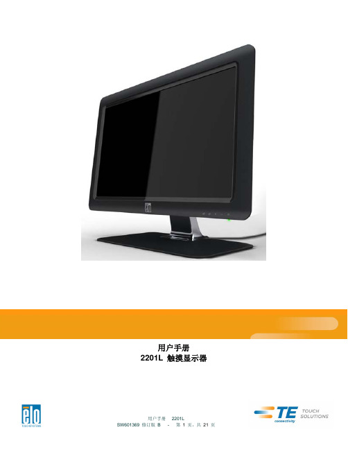
2201L 触摸显示器使用手册说明书

使用者手册2201L 觸摸顯示器版權所有© 2011 T yco Electronics。
保留所有權利。
未經 Tyco Electronics 的書面許可,不得以任何形式或方法(包括但不限於電子、磁性、光學、化學方法或手册等)複製、傳輸或改編本出版物的任何部分,不得將其儲存到擷取系統,不得將其翻譯成任何語言或電腦語言。
免責告示本文件中的訊息有可能在未通知的情况下進行變更。
Tyco Electronics 對本出版物的內容不提供任何形式的陳述或擔保,並且特別宣告拒絕對有特定目的適銷性或適用性提供任何默示擔保。
Tyco Electronics 保留對本出版物進行修訂並對其內容不斷進行變更,而不將這樣的修訂和變更通知任何人的權利。
商標告示Elo TouchSystems、IntelliTouch、iTouch、Tyco Electronics 和 TE(標誌)是 Tyco Electronics 集團公司及其許可方的商標。
Windows 為 Microsoft 集團公司的商標。
本文件中出現的其他產品名稱可能是其各自公司的商標或注册商標。
Tyco Electronics 對除自有商標以外的其他商標不享有任何權益。
目錄第 1 章 – 簡介 (4)第 2 章 – 安裝 (5)第 3 章 – 安裝 (9)第 4 章 – 操作 (10)第 5 章 – 技術支援 (14)第 6 章 – 安全與維護 (15)第 7 章 – 法規訊息 (16)第 8 章 – 擔保訊息 (19)第 1 章 – 簡介產品說明新的觸摸顯示器集 Elo TouchSystems 的可靠效能和觸摸技術與顯示屏設計領域的最新進展於一身。
這種功能組合可在使用者與觸摸顯示屏之間提供自然的訊息流動。
此觸摸顯示器帶有一個 24 位彩色有源矩陣薄膜晶體管 LCD 面板,提供了優异的顯示效能。
其全 HD 解析度 1920x1080 適合顯示圖形和影像。
威卡(WIKA)DPT-10型差压变送器说明书
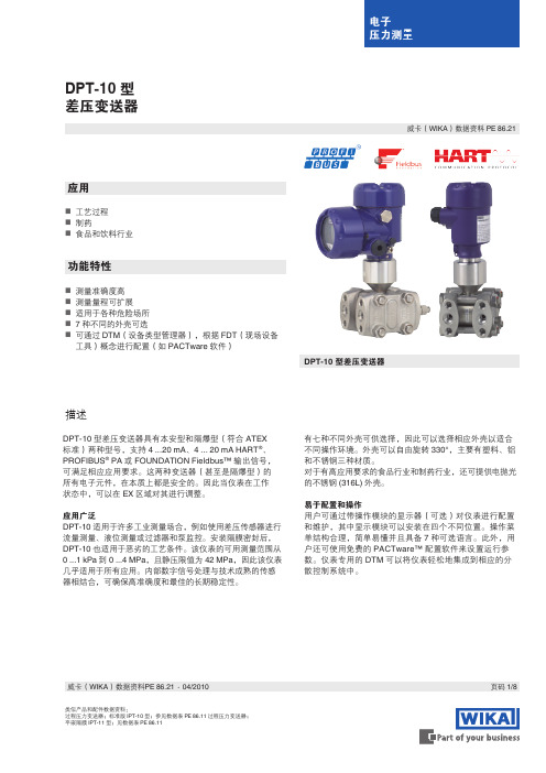
Bildunterschrift DPT-10 型差压变送器类似产品和配件数据资料:过程压力变送器;标准版 IPT-10 型;参见数据表 PE 86.11 过程压力变送器;平嵌隔膜 IPT-11 型;见数据表 PE 86.11应用⏹工艺过程制药食品和饮料行业⏹ ⏹功能特性⏹测量准确度高测量量程可扩展适用于各种危险场所7 种不同的外壳可选可通过 DTM (设备类型管理器),根据 FDT (现场设备工具)概念进行配置(如 PACTware 软件)DPT-10 型差压变送器⏹ ⏹ ⏹ ⏹描述威卡(WIKA)数据资料 PE 86.21页码 1/8威卡(WIKA )数据资料PE 86.21 ∙ 04/2010DPT-10 型差压变送器具有本安型和隔爆型(符合 ATEX标准)两种型号,支持 4 ...20 mA 、4 ... 20 mA HART ®、PROFIBUS ® PA 或 FOUNDATION Fieldbus™ 输出信号,可满足相应应用要求。
这两种变送器(甚至是隔爆型)的所有电子元件,在本质上都是安全的。
因此当仪表在工作状态中,可以在 EX 区域对其进行调整。
应用广泛DPT-10 适用于许多工业测量场合,例如使用差压传感器进行流量测量、液位测量或过滤器和泵监控。
安装隔膜密封后,DPT-10 也适用于恶劣的工艺条件。
该仪表的可用测量范围从0 ...1 kPa 到 0 ...4 MPa ,且静压限值为 42 MPa ,因此该仪表几乎适用于所有应用。
内部数字信号处理与技术成熟的传感器相结合,可确保高准确度和最佳的长期稳定性。
有七种不同外壳可供选择,因此可以选择相应外壳以适合不同操作环境。
外壳可以自由旋转 330°,主要有塑料、铝和不锈钢三种材质。
对于有高应用要求的食品行业和制药行业,还可提供电抛光的不锈钢 (316L) 外壳。
易于配置和操作用户可通过带操作模块的显示器(可选)对仪表进行配置和维护,其中显示模块可以安装在四个不同位置。
沃纳多 VH202 便携式取暖器 用户手册说明书

model PERSONAL HEATER OWNER’S GUIDEREAD AND SAVE THESE INSTRUCTIONS2English 800.234.0604****************We expect this product to beperfect.If it is not, we will make it right.Important Safety Instructions (4)Safety Features (8)Controls (9)How To Use (10)Cleaning (11)Storage (12)Reset Heater .....................................................................................12Troubleshooting . (13)Warranty (14)CONTENTS3EnglishREAD ALL INSTRUCTIONS BEFORE USING THIS HEATER IMPORTANT SAFETY INSTRUCTIONSThis owner’s guide and any additional inserts are considered part of the product. They contain important information about safety, use and disposal. Before using the product, please familiarize yourself with all operating and safety instructions. Please keep all documents for future reference and pass these documents on, together with the product, to any future owner. See to view, download and print the most current version of this owner’s guide.INTENDED USE: This product is intended to heat and circulate the air in indoor living spaces only. This product is not intended for commercial or industrial use. This heater is not intended for use in bathrooms, laundry areas, and similar damp locations. The manufacturer assumes no responsibility for damage or injury due to unauthorized use or product modification. Failure to follow these directions will void the product warranty. WARNING: When using electrical appliances, basic precautions should always be followed to reduce the risk of fire, electric shock, injury to persons, and hyperthermia, including the following:WARNING: Risk to Children and Impaired Persons- Extreme caution is required during the installation, operation, cleaning and maintenance of this product by or around children 12 years of age and younger and anyone with reduced physical, sensory or mental capabilities, and whenever the heater is left operating and unattended. Children should be supervised to ensure that they do not play with the appliance, its parts and packaging material. WARNING: Risk for Heat Stroke (Hyperthermia)- Hyperthermia can result in death. Symptoms of hyperthermia include high body temperature, headache, nausea, vomiting, tiredness, dizziness, fainting, and rapid pulse. If you begin to experience symptoms related to hyperthermia, turn off the heater and seek medical attention.- To avoid excessive room temperatures which can cause hyperthermia: DO NOT leave product running unattended in a confined space around infants, or individuals with reduced physical, sensory, or mental capabilities.4EnglishINSTALLATION WARNING—To reduce risk of fire, electrical shock and injury to persons, observe the following:- A heater has hot and arcing or sparking parts inside. Do not use it in areas where gasoline, paint, or flammable liquids are used or stored.- Do not use this heater in an RV, boat or during any application where battery power is converted to AC power.- Place this product at least 3 feet away on all sides from electrical outlets, furniture, pillows, bedding, papers, clothes, curtains and other objects that may cause or catch on fire. Do not place the heater near a bed because objects such as pillows or blankets can fall off the bed and be ignited by the heater.- To prevent a possible fire, do not place the heater on soft surfaces, like a bed, where air intakes or exhaust can be blocked in any manner.- No part of this product (the appliance, power cord, plug, packaging, etc.) should be placed near furnaces, fireplaces, stoves or other high temperature heat sources.- Do not use on an uneven or unstable surface.- Operate only in the upright position.- This appliance, power supply, power cord and plug cannot come into contact with water. Do not use this product on wet surfaces. Do not use this product in a bathtub or shower or position where it may fall into a bathtub, shower, laundry, swimming pool or other water container. Do not use in a window, outdoors, or exposed to weather or elements.- Do not run cord under carpeting. Do not cover cord with throw rugs, runners, or similar coverings. Do not route underfurniture or appliances. Arrange cord away from traffic area and where it will not be tripped over. The cord should not hang over edges of counters or be placed where it can be crimped or closed in doors. Place appliance near an easily accessible outlet so the product can be unplugged quickly during an emergency.- Do not modify the product with any aftermarket accessory. SAFE USE WARNING—To reduce risk of fire, electrical shock and injury to persons, observe the following:- Use this heater only as described in this manual. Any other use not recommended by the manufacturer may cause fire, electric shock, or injury to persons.- Extreme caution is required at all times a heater is in operation. Always unplug heater when not in use. Vornado does not recommend unattended and unsupervised use of this heater. - This heater is hot when in use. To avoid burns, do not let bare skin touch hot surfaces. If provided, use handles when moving this heater.- Always plug heaters directly into a wall outlet/receptacle. Never use with an extension cord or relocatable power tap (outlet/power strip).- Do not use this heater on a surge-protected unit or Ground Fault Circuit Interrupted (GFCI) outlet.- Before plugging power cord into electrical outlet, be sure that all electrical information on the rating label, including voltage, is compatible with your outlet’s power supply.- To reduce likelihood of circuit overload, fire and electric shock, do not operate with a solid state speed device, such as5Englisha dimmer control switch. Do not use this heater with a timer designed to automatically turn the unit on or off, as this may accidentally disable the heater’s thermal cutout safety feature. - Use of this appliance on the same electrical circuit as another high energy use product, such as a vacuum cleaner, blender, variable speed fan or circular saw is not advised.- Risk of fire. Do not operate any heater with a damaged cord or plug or after the heater malfunctions, has been dropped or damaged in any manner. Discard heater, or return to a Vornado authorized service facility for examination and/or repair.- Do not sit or stand on product.- Never use the cord as a handle or otherwise yank, strain or stretch the power cord.- Do not insert or allow foreign objects to enter any ventilation or exhaust opening as this may cause an electric shock or fire, or damage the heater.- Check your heater cord and plug connections. A loose fitting outlet can cause the plug to overheat or cause a fire. Be sure plug fits tight in the outlet. Check frequently during use to make sure plug and outlet are not hot. If so, discontinue using heater and have outlet replaced by a qualified electrician.- Never ignore the signs of an electrical problem, such as: warm outlet coverplates, sparks when plugging in or operating, lights flickering/dimming during operation. Immediately turn off and unplug the appliance if any such problems are noticed. Contact a qualified electrician to investigate possible causes before operating the appliance again.- Note: Heaters draw more current than small appliances,overheating of the outlet may occur even if it has not occurred with the other appliances.- Before moving, repositioning, servicing, cleaning and when not in use, use the product controls to turn off the power and then unplug. To disconnect from outlet, grasp and pull only the plug. Also, power off and unplug if the product will be left unattended for an extended period of time or during electrical storms.- This appliance has a polarized plug (one blade is wider than the other.) To reduce the risk of electrical shock, this plug is intended to fit in a polarized outlet only one way. If the plug does not fit fully in the outlet, reverse the plug. If it still does not fit, contact a qualified electrician. Do not attempt to defeat this safety feature.- If your heater suddenly stops working:• This heater is equipped with a thermal cutout safety feature designed to automatically shut off when overheating isdetected. See the “RESET HEATER” instructions in thisguide to determine how to check and reset the heater. • If the heater and other electrical products suddenly stopworking at the same time, your home circuit breakeror fuse may have tripped due to an overload of power.Consider only running your heater on the “low” setting,only running one heater at once and unplugging all other electrical products while running the heater, and/or hiring an electrician to install an additional circuit to your home’s electrical system.6EnglishSERVICING WARNING—To reduce risk of fire, electricalshock and injury to persons, observe the following:- Clean your product regularly, only as is instructed in thismanual. Prior to cleaning, turn off the power on yourproduct and unplug. Do not use gasoline, thinners, solvents,ammonias or other chemicals for cleaning. Refer to theCLEANING instructions provided.- Do not open appliance housing while product is plugged in.To avoid risk of shock, all service and/or repairs must be doneby a Vornado Authorized Service Center.SAVE THESEINSTRUCTIONSEnglish78EnglishSAFETY FEATURESTIP-OVER: If heater tips over, safety shut-off system cuts power to heater, and the red indicator light will illuminate until you position the heater back inupright position and power is restored.AUTOMATIC SAFETY SHUT -OFF SYSTEMIf airflow becomes blocked, power to heater is shut off to prevent overheating.AUTOMATIC TIP-OVER PROTECTION If tipped more than 10 degrees in anyFINGER-FRIENDLY DESIGN Resists curious fingers.COOL-TOUCH CASESafe to touch, even on high heat setting.9English CONTROLSOff (O) On ( – )MODELow Heat (I) 375 watts,Fan Only orHigh Heat (II) 750 watts.10EnglishHOW TO USEBefore use, check appliance for visible damage. DO NOT USE THIS HEATER if there is evidence of damage. If any damage is found, contact Vornado Air LLC at 1-800-234-0604.3. Plug power cord into standard grounded wall outlet.2. Position heater so airflow is not obstructed.1. Use integrated handle on back of heater for lifting and carrying.4.and select Mode. The amber light illuminates to indicate the heater is on. To use as personal fan, select the center position on the switchfor Fan Only.11English CLEANINGBecause your heater moves a substantial amount of air, it will need regular cleaning. Cleaning the outside of the heater is recommended on a weekly basis. If service is required, return your heater to Vornado. See WARRANTY for instructions.1. Unplug heater before cleaning.2. Use brush attachment on household vacuum cleaner to vacuum any accumulated dust off Air Inlets on sides.Do not modify the product You should periodically blow out the heater with pressurized air to keep heat element and12EnglishDuring the off-season or after extended periods of non-use, you may choose to store your heater. To ensure long life of the product, it is recommended to store your heater by following these instructions:1. Unplug power cord and bundle loosely.2. Cover, or place back in retail carton if available. This prevents heater from accumulating dust over time.3. Store heater in cool and dry location.RESETTING YOUR VORNADO HEATERYour Vornado Heater has a multilevel safety shut-off system designed to prevent overheating. Overheating may occur when the inlets or outlet are blocked. If this happens, the safety shut-off system cuts power to the heater and you must to manually reset the heater.1. Power heater off, then unplug power cord.2. Remove any obstructions.3. Wait 5–10 minutes, allowing heater to cool down.4. Plug in power cord and place heater in desired position.5. Press Power switch On. Your Vornado Heater should now function normally.If the heater’s red indicator light remains illuminated even after positioning the heater back in upright position after being tipped over, the heater may have overheated and will need to be reset as directed above.Note: If the safety shut-off system repeatedly shuts off your heater or if it will not reset after following the above procedure, call Vornado Consumer Services Department toll-free at 1-800-234-0604.STORAGERESET HEATERCleaning is recommended before storage.DISPOSALDispose of all packagingmaterials in an environmentally responsible manner.TROUBLESHOOTINGEnglish13Vornado Air LLC (“Vornado”) warrants to the original consumer or purchaser this Vornado® Whole Room Heater (“Product”) is free from defects in material or workmanship for a period of three (3) years from the date of purchase. If any such defect is discovered within the warranty period, Vornado, at its discretion, will repair or replace the Product at no cost.Forwarrantyservice:******************************************************** Authorization (“RA”). Please have or include your Product’s model number and serial number, as well as your name, address, city, state, zip code, e-mail, and phone number when contacting Vornado for warranty service. Or to file a contactless warranty claim, visit /contact-us.After receiving the RA form, ship your Product to: Vornado Air LLC Attn: Warranty & Repair 415 East 13th Street Andover, KS 67002. For your convenience, please have your model number and serial number when contacting Vornado with service inquiries. To assure proper handling, packages must be clearly marked with the RA number. Packages not clearly marked with the RA number may be refused at the receiving dock. Please allow 2-3 weeks for warranty service and return of your Product after the Product is received.This warranty does not apply to defects resulting from abuse of the Product, modification, alteration, mishandling, improper maintenance, commercial use or repair or service of the Product by anyone other than Vornado; damages which occur in shipment or are attributed to acts of God. Improper product use, which includes using an external device thatalters or converts the voltage or frequency of electricity, or shipping a Vornado productto a country not intended for use will void all warranties. Any unauthorized product modification, repair by unauthorized repair center, or use of non-approved replacement parts is not recommended and any consequences will not be covered by support services or product warranties. The product warranty will be honored only on models that are being used in the country intended. REPAIR OR REPLACEMENT AS PROVIDED UNDER THIS WARRANTY IS THE EXCLUSIVE REMEDY OF THE CONSUMER. VORNADO SHALL NOT BE LIABLE FOR ANY INCIDENTAL OR CONSEQUENTIAL DAMAGES FOR BREACH OF ANY EXPRESS OR IMPLIED WARRANTY ON THIS PRODUCT. EXCEPT TO THE EXTENT PROHIBITED BY APPLICABLE LAW, ANY IMPLIED WARRANTY OF MERCHANTABILITY OR FITNESS FOR A PARTICULAR PURPOSE ON THIS PRODUCT IS LIMITED IN DURATION TO THE DURATION OF THIS WARRANTY. Some states do not allow the exclusion or limitation of incidental or consequential damages, or allow limitations on how long an implied warranty lasts, so the above limitations or exclusions may not apply to you. This warranty gives you specific legal rights, and you may have other rights that vary from state to state. The manufacturer assumes no responsibility for damage caused by failureto follow these instructions or improper product use. Any such actions will invalidate the product warranty.All company names and product names are trademarks of their respective owners. ©All rights reserved. All technical information, data, and instructions for the installation, connection, and operation contained in these instructions for use correspond to the latest available information at time of printing. The contents of this manual may differ slightly from the actual product. Observe any additional supplements.WARRANTYWe expect this product to be perfect. If you’re not satisfied with this product, let us know.We’re Here to Help 800.234.0604 ****************14English。
VOC显示器使用说明书
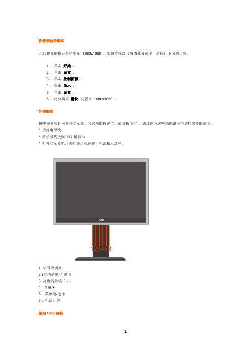
1
• 按 MENU 按钮激活 OSD 窗口。 • 按 - 或+ 浏览这些功能。 如果想要调整的功能突出显示,按 MENU 按钮激活它。如果所选的
功能包含有子菜单,再按一下 - 或+ 可以浏览到子菜单功能。如果想要调整的功能突出显示, 按 MENU 按钮激活它。 • 按 - 或+ 更改所选功能的设置。要退出和保存,请选择退出功能。 • 如果您想调整其它任何功能,请重复步骤 2-3 。 • OSD 锁定功能: 要锁定 OSD ,请在显示器关闭时按住 菜单 按钮,然后按电源按钮打开显 示器。 要解锁 OSD ,请在显示器关闭时按住 菜单 按钮,然后按电源按钮打开显示器。 • 亮度情景模式快捷键: 当没有 OSD 菜单时, 连续按 Eco 快捷键可选择不同的亮度情景模式(部分 机型可能不适用). • 音量快捷键: 当没有 OSD 菜单时, 按音量快捷键(+)激活音量调整菜单, 按 - 或 + 调节音量大 小(仅针对带喇叭机型) • 信号源快捷键: 当没有 OSD 菜单时, 按信号源快捷键激活信号源功能(仅针两种输入信号及以上 机型) ,连续按 source 键来选择信息栏中显示的信号源,按 menu/enter 键调整为选择的信号源。 • 自动调整快捷键: 当没有 OSD 菜单时, 按自动调整快捷键可启动自动调整功能
DCB 活彩技术调整
什么是活彩技术? 活彩技术(DCB)是一种高端色彩调节技术,它通过对 RGB 信号的解析而创造出更加生动自然的画面,
2
以适应不同的环境需求。活彩技术包括色彩增强及窗口增亮 2 种功能。 DCC: 动态色彩控制 ICM: 智能色彩管理 1) 如何使用色彩增强? 5 种色彩增强模式:为适用于不同的显示模式,色彩增强提供了 5 种应用模式:全色增强,自然肤色,绿 茵场景,蔚蓝风景,以及自动监测。请在色彩增强主菜单中选择您需要的模式。
富威德10.1寸航拍监视器中文说明书

使 用 说 明 书32频道自动搜索无线航拍双通道分集接收(内置DVR)LCD 液晶监视器产品简介:双天线双通道交集接收无线航拍(内置DVR)LCD 液晶监视器是一款新型的多用途的产品,采用先进的集成电路及优质新型的高清液晶显示器。
它采用了双通道高灵敏度的5.8G无线交集接收、集成了航拍接收、录像机、高清监视器为一体,不但可以进行现场无线接收,监看,还可以对拍摄过程进行无缝录像、即时图像抓拍,录像回放。
监视器还配备有内置电池,也可选择装配外置电池扣板或者通过电源适配器由市电进行供电。
机器外观小巧,操作方便。
可应用于航拍地面站、车载录像监视器(行车记录仪)、安防监控、婴儿监视器、摄影取景器、新闻现场采访、工程施工现场图像监控。
广告机等多种应用场地。
使用产品前,为达到最佳使用效果,请阅读本说明书,注意事项1. 请采用合格的电池或符合要求的电源适配器进行供电,采用电池供电时应注意电池是否处于足够的供电容量。
当电池容量不足时应及时对电池进行充电。
2. 不要将机子放于日光下爆晒,也不要在过冷过热或潮湿的地方存放、使用。
3. 使用时显示屏幕应避开强光照射,以保证图像效果及机子的长期使用。
如果需要在户外进行监控,可使用遮阳罩。
4. 机子内部虽有防震保护措施,但还应避免剧烈碰撞。
5. 不要用化学试剂或溶剂擦洗机子.请用软布擦除机子上的尘污,以保证本机的亮丽。
6. 机内无用户可调组件,非专业人员,请勿自行打开本机或自行尝试修理本产品!以免造成不必要的损坏。
产品特点●双天线两通道高频头分集接收,灵敏度高、方向性小、抗干扰强●集无线5.8G微波接收、监视器、DVR为一体化多功能组合机,体积小巧,适合多种用途●即时屏幕图像抓拍功能,保存最美时刻●DVR无缝录像,保存最新数据●运动检测录像,节省记忆体空间●5.8G无线接收、32通道自动搜索,有效避开信号干扰 ●超高亮度,对比度防眩屏搭配遮阳罩,阳光下清晰可见 ●具备视频VIDEO输入、输出,HDMI输入,适合多种信号源。
胜利仪器 VICTOR 220 2061 2101双通道手持式示波表说明书

目录1.产品证书ꞏꞏꞏꞏꞏꞏꞏꞏꞏꞏꞏꞏꞏꞏꞏꞏꞏꞏꞏꞏꞏꞏꞏꞏꞏꞏꞏꞏꞏꞏꞏꞏꞏꞏꞏꞏꞏꞏꞏꞏꞏꞏꞏꞏꞏꞏꞏꞏꞏꞏꞏꞏꞏꞏꞏꞏꞏꞏꞏꞏꞏ11.1产品证书ꞏꞏꞏꞏꞏꞏꞏꞏꞏꞏꞏꞏꞏꞏꞏꞏꞏꞏꞏꞏꞏꞏꞏꞏꞏꞏꞏꞏꞏꞏꞏꞏꞏꞏꞏꞏꞏꞏꞏꞏꞏꞏꞏꞏꞏꞏꞏꞏꞏꞏꞏꞏꞏꞏꞏꞏꞏꞏꞏꞏꞏꞏꞏꞏꞏꞏꞏꞏꞏꞏꞏꞏꞏꞏꞏꞏꞏꞏꞏꞏꞏꞏꞏꞏꞏꞏꞏꞏꞏꞏꞏꞏꞏꞏꞏꞏꞏꞏꞏꞏꞏꞏꞏꞏꞏ1 1.2示波表套件清单ꞏꞏꞏꞏꞏꞏꞏꞏꞏꞏꞏꞏꞏꞏꞏꞏꞏꞏꞏꞏꞏꞏꞏꞏꞏꞏꞏꞏꞏꞏꞏꞏꞏꞏꞏꞏꞏꞏꞏꞏꞏꞏꞏꞏꞏꞏꞏꞏꞏꞏꞏꞏꞏꞏꞏꞏꞏꞏꞏꞏꞏꞏꞏꞏꞏꞏꞏꞏꞏꞏꞏꞏꞏꞏꞏꞏꞏꞏꞏꞏꞏꞏꞏꞏꞏꞏꞏꞏꞏꞏꞏꞏꞏꞏꞏꞏ22.安全信息ꞏꞏꞏꞏꞏꞏꞏꞏꞏꞏꞏꞏꞏꞏꞏꞏꞏꞏꞏꞏꞏꞏꞏꞏꞏꞏꞏꞏꞏꞏꞏꞏꞏꞏꞏꞏꞏꞏꞏꞏꞏꞏꞏꞏꞏꞏꞏꞏꞏꞏꞏꞏꞏꞏꞏꞏꞏꞏꞏꞏꞏ32.1安全术语和符号ꞏꞏꞏꞏꞏꞏꞏꞏꞏꞏꞏꞏꞏꞏꞏꞏꞏꞏꞏꞏꞏꞏꞏꞏꞏꞏꞏꞏꞏꞏꞏꞏꞏꞏꞏꞏꞏꞏꞏꞏꞏꞏꞏꞏꞏꞏꞏꞏꞏꞏꞏꞏꞏꞏꞏꞏꞏꞏꞏꞏꞏꞏꞏꞏꞏꞏꞏꞏꞏꞏꞏꞏꞏꞏꞏꞏꞏꞏꞏꞏꞏꞏꞏꞏꞏꞏꞏꞏꞏꞏꞏꞏꞏꞏꞏꞏ3 2.1.1本手册中的术语ꞏꞏꞏꞏꞏꞏꞏꞏꞏꞏꞏꞏꞏꞏꞏꞏꞏꞏꞏꞏꞏꞏꞏꞏꞏꞏꞏꞏꞏꞏꞏꞏꞏꞏꞏꞏꞏꞏꞏꞏꞏꞏꞏꞏꞏꞏꞏꞏꞏꞏꞏꞏꞏꞏꞏꞏꞏꞏꞏꞏꞏꞏꞏꞏꞏꞏꞏꞏꞏꞏꞏꞏꞏꞏꞏꞏꞏꞏꞏꞏꞏꞏꞏꞏꞏꞏꞏꞏꞏꞏ3 2.1.2产品上的术语ꞏꞏꞏꞏꞏꞏꞏꞏꞏꞏꞏꞏꞏꞏꞏꞏꞏꞏꞏꞏꞏꞏꞏꞏꞏꞏꞏꞏꞏꞏꞏꞏꞏꞏꞏꞏꞏꞏꞏꞏꞏꞏꞏꞏꞏꞏꞏꞏꞏꞏꞏꞏꞏꞏꞏꞏꞏꞏꞏꞏꞏꞏꞏꞏꞏꞏꞏꞏꞏꞏꞏꞏꞏꞏꞏꞏꞏꞏꞏꞏꞏꞏꞏꞏꞏꞏꞏꞏꞏꞏꞏꞏꞏ3 2.1.3产品上的符号ꞏꞏꞏꞏꞏꞏꞏꞏꞏꞏꞏꞏꞏꞏꞏꞏꞏꞏꞏꞏꞏꞏꞏꞏꞏꞏꞏꞏꞏꞏꞏꞏꞏꞏꞏꞏꞏꞏꞏꞏꞏꞏꞏꞏꞏꞏꞏꞏꞏꞏꞏꞏꞏꞏꞏꞏꞏꞏꞏꞏꞏꞏꞏꞏꞏꞏꞏꞏꞏꞏꞏꞏꞏꞏꞏꞏꞏꞏꞏꞏꞏꞏꞏꞏꞏꞏꞏꞏꞏꞏꞏꞏꞏ3 2.2安全要求ꞏꞏꞏꞏꞏꞏꞏꞏꞏꞏꞏꞏꞏꞏꞏꞏꞏꞏꞏꞏꞏꞏꞏꞏꞏꞏꞏꞏꞏꞏꞏꞏꞏꞏꞏꞏꞏꞏꞏꞏꞏꞏꞏꞏꞏꞏꞏꞏꞏꞏꞏꞏꞏꞏꞏꞏꞏꞏꞏꞏꞏꞏꞏꞏꞏꞏꞏꞏꞏꞏꞏꞏꞏꞏꞏꞏꞏꞏꞏꞏꞏꞏꞏꞏꞏꞏꞏꞏꞏꞏꞏꞏꞏꞏꞏꞏꞏꞏꞏꞏꞏꞏꞏꞏꞏ43.VICTOR系列示波表一般特点ꞏꞏꞏꞏꞏꞏꞏꞏꞏꞏꞏꞏꞏꞏꞏꞏꞏꞏꞏꞏꞏꞏꞏꞏꞏꞏꞏꞏꞏꞏꞏꞏꞏꞏ74.如何进行一般性检查ꞏꞏꞏꞏꞏꞏꞏꞏꞏꞏꞏꞏꞏꞏꞏꞏꞏꞏꞏꞏꞏꞏꞏꞏꞏꞏꞏꞏꞏꞏꞏꞏꞏꞏꞏꞏꞏꞏꞏꞏꞏꞏꞏꞏꞏꞏ84.1如何进行一般性检查ꞏꞏꞏꞏꞏꞏꞏꞏꞏꞏꞏꞏꞏꞏꞏꞏꞏꞏꞏꞏꞏꞏꞏꞏꞏꞏꞏꞏꞏꞏꞏꞏꞏꞏꞏꞏꞏꞏꞏꞏꞏꞏꞏꞏꞏꞏꞏꞏꞏꞏꞏꞏꞏꞏꞏꞏꞏꞏꞏꞏꞏꞏꞏꞏꞏꞏꞏꞏꞏꞏꞏꞏꞏꞏꞏꞏꞏꞏꞏꞏꞏꞏꞏꞏꞏꞏꞏꞏꞏꞏ8 4.1.1检查是否存在因运输造成的损坏ꞏꞏꞏꞏꞏꞏꞏꞏꞏꞏꞏꞏꞏꞏꞏꞏꞏꞏꞏꞏꞏꞏꞏꞏꞏꞏꞏꞏꞏꞏꞏꞏꞏꞏꞏꞏꞏꞏꞏꞏꞏꞏꞏꞏꞏꞏꞏꞏꞏꞏꞏꞏꞏꞏꞏꞏꞏꞏꞏꞏꞏꞏꞏꞏꞏꞏꞏꞏꞏ8 4.1.2检查附件ꞏꞏꞏꞏꞏꞏꞏꞏꞏꞏꞏꞏꞏꞏꞏꞏꞏꞏꞏꞏꞏꞏꞏꞏꞏꞏꞏꞏꞏꞏꞏꞏꞏꞏꞏꞏꞏꞏꞏꞏꞏꞏꞏꞏꞏꞏꞏꞏꞏꞏꞏꞏꞏꞏꞏꞏꞏꞏꞏꞏꞏꞏꞏꞏꞏꞏꞏꞏꞏꞏꞏꞏꞏꞏꞏꞏꞏꞏꞏꞏꞏꞏꞏꞏꞏꞏꞏꞏꞏꞏꞏꞏꞏꞏꞏꞏꞏꞏꞏ8 4.1.3检查整机ꞏꞏꞏꞏꞏꞏꞏꞏꞏꞏꞏꞏꞏꞏꞏꞏꞏꞏꞏꞏꞏꞏꞏꞏꞏꞏꞏꞏꞏꞏꞏꞏꞏꞏꞏꞏꞏꞏꞏꞏꞏꞏꞏꞏꞏꞏꞏꞏꞏꞏꞏꞏꞏꞏꞏꞏꞏꞏꞏꞏꞏꞏꞏꞏꞏꞏꞏꞏꞏꞏꞏꞏꞏꞏꞏꞏꞏꞏꞏꞏꞏꞏꞏꞏꞏꞏꞏꞏꞏꞏꞏꞏꞏꞏꞏꞏꞏꞏꞏ85.示波表连接ꞏꞏꞏꞏꞏꞏꞏꞏꞏꞏꞏꞏꞏꞏꞏꞏꞏꞏꞏꞏꞏꞏꞏꞏꞏꞏꞏꞏꞏꞏꞏꞏꞏꞏꞏꞏꞏꞏꞏꞏꞏꞏꞏꞏꞏꞏꞏꞏꞏꞏꞏꞏꞏꞏꞏꞏꞏꞏ95.1示波表的连接ꞏꞏꞏꞏꞏꞏꞏꞏꞏꞏꞏꞏꞏꞏꞏꞏꞏꞏꞏꞏꞏꞏꞏꞏꞏꞏꞏꞏꞏꞏꞏꞏꞏꞏꞏꞏꞏꞏꞏꞏꞏꞏꞏꞏꞏꞏꞏꞏꞏꞏꞏꞏꞏꞏꞏꞏꞏꞏꞏꞏꞏꞏꞏꞏꞏꞏꞏꞏꞏꞏꞏꞏꞏꞏꞏꞏꞏꞏꞏꞏꞏꞏꞏꞏꞏꞏꞏꞏꞏꞏꞏꞏꞏꞏꞏꞏꞏꞏꞏ9 5.1.1示波表的连接ꞏꞏꞏꞏꞏꞏꞏꞏꞏꞏꞏꞏꞏꞏꞏꞏꞏꞏꞏꞏꞏꞏꞏꞏꞏꞏꞏꞏꞏꞏꞏꞏꞏꞏꞏꞏꞏꞏꞏꞏꞏꞏꞏꞏꞏꞏꞏꞏꞏꞏꞏꞏꞏꞏꞏꞏꞏꞏꞏꞏꞏꞏꞏꞏꞏꞏꞏꞏꞏꞏꞏꞏꞏꞏꞏꞏꞏꞏꞏꞏꞏꞏꞏꞏꞏꞏꞏꞏꞏꞏꞏꞏꞏ9 5.1.21kHz/5V方波测试信号输出连接ꞏꞏꞏꞏꞏꞏꞏꞏꞏꞏꞏꞏꞏꞏꞏꞏꞏꞏꞏꞏꞏꞏꞏꞏꞏꞏꞏꞏꞏꞏꞏꞏꞏꞏꞏꞏꞏꞏꞏꞏꞏꞏꞏꞏꞏꞏꞏꞏꞏꞏꞏꞏꞏꞏꞏꞏꞏꞏꞏꞏꞏꞏꞏꞏꞏ10 5.2示波表前面板和按键ꞏꞏꞏꞏꞏꞏꞏꞏꞏꞏꞏꞏꞏꞏꞏꞏꞏꞏꞏꞏꞏꞏꞏꞏꞏꞏꞏꞏꞏꞏꞏꞏꞏꞏꞏꞏꞏꞏꞏꞏꞏꞏꞏꞏꞏꞏꞏꞏꞏꞏꞏꞏꞏꞏꞏꞏꞏꞏꞏꞏꞏꞏꞏꞏꞏꞏꞏꞏꞏꞏꞏꞏꞏꞏꞏꞏꞏꞏꞏꞏꞏꞏꞏꞏꞏꞏꞏꞏ106.初步使用示波器ꞏꞏꞏꞏꞏꞏꞏꞏꞏꞏꞏꞏꞏꞏꞏꞏꞏꞏꞏꞏꞏꞏꞏꞏꞏꞏꞏꞏꞏꞏꞏꞏꞏꞏꞏꞏꞏꞏꞏꞏꞏꞏꞏꞏꞏꞏꞏꞏꞏꞏꞏ136.1关于本章ꞏꞏꞏꞏꞏꞏꞏꞏꞏꞏꞏꞏꞏꞏꞏꞏꞏꞏꞏꞏꞏꞏꞏꞏꞏꞏꞏꞏꞏꞏꞏꞏꞏꞏꞏꞏꞏꞏꞏꞏꞏꞏꞏꞏꞏꞏꞏꞏꞏꞏꞏꞏꞏꞏꞏꞏꞏꞏꞏꞏꞏꞏꞏꞏꞏꞏꞏꞏꞏꞏꞏꞏꞏꞏꞏꞏꞏꞏꞏꞏꞏꞏꞏꞏꞏꞏꞏꞏꞏꞏꞏꞏꞏꞏꞏꞏꞏꞏꞏꞏꞏꞏꞏꞏ13 6.2接通示波表的电源ꞏꞏꞏꞏꞏꞏꞏꞏꞏꞏꞏꞏꞏꞏꞏꞏꞏꞏꞏꞏꞏꞏꞏꞏꞏꞏꞏꞏꞏꞏꞏꞏꞏꞏꞏꞏꞏꞏꞏꞏꞏꞏꞏꞏꞏꞏꞏꞏꞏꞏꞏꞏꞏꞏꞏꞏꞏꞏꞏꞏꞏꞏꞏꞏꞏꞏꞏꞏꞏꞏꞏꞏꞏꞏꞏꞏꞏꞏꞏꞏꞏꞏꞏꞏꞏꞏꞏꞏꞏꞏꞏ13 6.3示波器显示界面说明ꞏꞏꞏꞏꞏꞏꞏꞏꞏꞏꞏꞏꞏꞏꞏꞏꞏꞏꞏꞏꞏꞏꞏꞏꞏꞏꞏꞏꞏꞏꞏꞏꞏꞏꞏꞏꞏꞏꞏꞏꞏꞏꞏꞏꞏꞏꞏꞏꞏꞏꞏꞏꞏꞏꞏꞏꞏꞏꞏꞏꞏꞏꞏꞏꞏꞏꞏꞏꞏꞏꞏꞏꞏꞏꞏꞏꞏꞏꞏꞏꞏꞏꞏꞏꞏꞏꞏꞏ13 6.4菜单的使用方法ꞏꞏꞏꞏꞏꞏꞏꞏꞏꞏꞏꞏꞏꞏꞏꞏꞏꞏꞏꞏꞏꞏꞏꞏꞏꞏꞏꞏꞏꞏꞏꞏꞏꞏꞏꞏꞏꞏꞏꞏꞏꞏꞏꞏꞏꞏꞏꞏꞏꞏꞏꞏꞏꞏꞏꞏꞏꞏꞏꞏꞏꞏꞏꞏꞏꞏꞏꞏꞏꞏꞏꞏꞏꞏꞏꞏꞏꞏꞏꞏꞏꞏꞏꞏꞏꞏꞏꞏꞏꞏꞏꞏꞏꞏ15 6.5手动设置垂直系统、水平系统和触发位置ꞏꞏꞏꞏꞏꞏꞏꞏꞏꞏꞏꞏꞏꞏꞏꞏꞏꞏꞏꞏꞏꞏꞏꞏꞏꞏꞏꞏꞏꞏꞏꞏꞏꞏꞏꞏꞏꞏꞏꞏꞏꞏꞏꞏꞏꞏꞏꞏꞏꞏꞏꞏꞏꞏꞏꞏꞏꞏꞏꞏꞏ15 6.5.1设置垂直系统ꞏꞏꞏꞏꞏꞏꞏꞏꞏꞏꞏꞏꞏꞏꞏꞏꞏꞏꞏꞏꞏꞏꞏꞏꞏꞏꞏꞏꞏꞏꞏꞏꞏꞏꞏꞏꞏꞏꞏꞏꞏꞏꞏꞏꞏꞏꞏꞏꞏꞏꞏꞏꞏꞏꞏꞏꞏꞏꞏꞏꞏꞏꞏꞏꞏꞏꞏꞏꞏꞏꞏꞏꞏꞏꞏꞏꞏꞏꞏꞏꞏꞏꞏꞏꞏꞏꞏꞏꞏꞏꞏꞏꞏ15 6.5.2设置水平系统和触发位置ꞏꞏꞏꞏꞏꞏꞏꞏꞏꞏꞏꞏꞏꞏꞏꞏꞏꞏꞏꞏꞏꞏꞏꞏꞏꞏꞏꞏꞏꞏꞏꞏꞏꞏꞏꞏꞏꞏꞏꞏꞏꞏꞏꞏꞏꞏꞏꞏꞏꞏꞏꞏꞏꞏꞏꞏꞏꞏꞏꞏꞏꞏꞏꞏꞏꞏꞏꞏꞏꞏꞏꞏꞏꞏꞏꞏꞏꞏ16 6.6重新设置示波表ꞏꞏꞏꞏꞏꞏꞏꞏꞏꞏꞏꞏꞏꞏꞏꞏꞏꞏꞏꞏꞏꞏꞏꞏꞏꞏꞏꞏꞏꞏꞏꞏꞏꞏꞏꞏꞏꞏꞏꞏꞏꞏꞏꞏꞏꞏꞏꞏꞏꞏꞏꞏꞏꞏꞏꞏꞏꞏꞏꞏꞏꞏꞏꞏꞏꞏꞏꞏꞏꞏꞏꞏꞏꞏꞏꞏꞏꞏꞏꞏꞏꞏꞏꞏꞏꞏꞏꞏꞏꞏꞏꞏꞏꞏ19 6.7输入端口连接ꞏꞏꞏꞏꞏꞏꞏꞏꞏꞏꞏꞏꞏꞏꞏꞏꞏꞏꞏꞏꞏꞏꞏꞏꞏꞏꞏꞏꞏꞏꞏꞏꞏꞏꞏꞏꞏꞏꞏꞏꞏꞏꞏꞏꞏꞏꞏꞏꞏꞏꞏꞏꞏꞏꞏꞏꞏꞏꞏꞏꞏꞏꞏꞏꞏꞏꞏꞏꞏꞏꞏꞏꞏꞏꞏꞏꞏꞏꞏꞏꞏꞏꞏꞏꞏꞏꞏꞏꞏꞏꞏꞏꞏꞏꞏꞏꞏ20 6.8使用自动设置显示不明信号ꞏꞏꞏꞏꞏꞏꞏꞏꞏꞏꞏꞏꞏꞏꞏꞏꞏꞏꞏꞏꞏꞏꞏꞏꞏꞏꞏꞏꞏꞏꞏꞏꞏꞏꞏꞏꞏꞏꞏꞏꞏꞏꞏꞏꞏꞏꞏꞏꞏꞏꞏꞏꞏꞏꞏꞏꞏꞏꞏꞏꞏꞏꞏꞏꞏꞏꞏꞏꞏꞏꞏꞏꞏꞏꞏꞏꞏꞏꞏ20 6.9触发水平位置、触发电平位置自动回零ꞏꞏꞏꞏꞏꞏꞏꞏꞏꞏꞏꞏꞏꞏꞏꞏꞏꞏꞏꞏꞏꞏꞏꞏꞏꞏꞏꞏꞏꞏꞏꞏꞏꞏꞏꞏꞏꞏꞏꞏꞏꞏꞏꞏꞏꞏꞏꞏꞏꞏꞏꞏꞏꞏꞏꞏꞏꞏꞏꞏꞏꞏꞏꞏ20 6.10进行自动示波器测量ꞏꞏꞏꞏꞏꞏꞏꞏꞏꞏꞏꞏꞏꞏꞏꞏꞏꞏꞏꞏꞏꞏꞏꞏꞏꞏꞏꞏꞏꞏꞏꞏꞏꞏꞏꞏꞏꞏꞏꞏꞏꞏꞏꞏꞏꞏꞏꞏꞏꞏꞏꞏꞏꞏꞏꞏꞏꞏꞏꞏꞏꞏꞏꞏꞏꞏꞏꞏꞏꞏꞏꞏꞏꞏꞏꞏꞏꞏꞏꞏꞏꞏꞏꞏꞏꞏꞏ20 6.11屏幕锁定ꞏꞏꞏꞏꞏꞏꞏꞏꞏꞏꞏꞏꞏꞏꞏꞏꞏꞏꞏꞏꞏꞏꞏꞏꞏꞏꞏꞏꞏꞏꞏꞏꞏꞏꞏꞏꞏꞏꞏꞏꞏꞏꞏꞏꞏꞏꞏꞏꞏꞏꞏꞏꞏꞏꞏꞏꞏꞏꞏꞏꞏꞏꞏꞏꞏꞏꞏꞏꞏꞏꞏꞏꞏꞏꞏꞏꞏꞏꞏꞏꞏꞏꞏꞏꞏꞏꞏꞏꞏꞏꞏꞏꞏꞏꞏꞏꞏꞏꞏꞏꞏꞏ216.12使用平均处理使波形平滑ꞏꞏꞏꞏꞏꞏꞏꞏꞏꞏꞏꞏꞏꞏꞏꞏꞏꞏꞏꞏꞏꞏꞏꞏꞏꞏꞏꞏꞏꞏꞏꞏꞏꞏꞏꞏꞏꞏꞏꞏꞏꞏꞏꞏꞏꞏꞏꞏꞏꞏꞏꞏꞏꞏꞏꞏꞏꞏꞏꞏꞏꞏꞏꞏꞏꞏꞏꞏꞏꞏꞏꞏꞏꞏꞏꞏꞏꞏꞏꞏꞏ22 6.13使用余辉显示波形ꞏꞏꞏꞏꞏꞏꞏꞏꞏꞏꞏꞏꞏꞏꞏꞏꞏꞏꞏꞏꞏꞏꞏꞏꞏꞏꞏꞏꞏꞏꞏꞏꞏꞏꞏꞏꞏꞏꞏꞏꞏꞏꞏꞏꞏꞏꞏꞏꞏꞏꞏꞏꞏꞏꞏꞏꞏꞏꞏꞏꞏꞏꞏꞏꞏꞏꞏꞏꞏꞏꞏꞏꞏꞏꞏꞏꞏꞏꞏꞏꞏꞏꞏꞏꞏꞏꞏꞏꞏꞏ22 6.14使用峰值检测功能显示尖峰脉冲ꞏꞏꞏꞏꞏꞏꞏꞏꞏꞏꞏꞏꞏꞏꞏꞏꞏꞏꞏꞏꞏꞏꞏꞏꞏꞏꞏꞏꞏꞏꞏꞏꞏꞏꞏꞏꞏꞏꞏꞏꞏꞏꞏꞏꞏꞏꞏꞏꞏꞏꞏꞏꞏꞏꞏꞏꞏꞏꞏꞏꞏꞏꞏꞏꞏꞏꞏꞏꞏꞏꞏꞏ23 6.15选择交流耦合ꞏꞏꞏꞏꞏꞏꞏꞏꞏꞏꞏꞏꞏꞏꞏꞏꞏꞏꞏꞏꞏꞏꞏꞏꞏꞏꞏꞏꞏꞏꞏꞏꞏꞏꞏꞏꞏꞏꞏꞏꞏꞏꞏꞏꞏꞏꞏꞏꞏꞏꞏꞏꞏꞏꞏꞏꞏꞏꞏꞏꞏꞏꞏꞏꞏꞏꞏꞏꞏꞏꞏꞏꞏꞏꞏꞏꞏꞏꞏꞏꞏꞏꞏꞏꞏꞏꞏꞏꞏꞏꞏꞏꞏꞏꞏꞏ24 6.16翻转所显示波形的极性ꞏꞏꞏꞏꞏꞏꞏꞏꞏꞏꞏꞏꞏꞏꞏꞏꞏꞏꞏꞏꞏꞏꞏꞏꞏꞏꞏꞏꞏꞏꞏꞏꞏꞏꞏꞏꞏꞏꞏꞏꞏꞏꞏꞏꞏꞏꞏꞏꞏꞏꞏꞏꞏꞏꞏꞏꞏꞏꞏꞏꞏꞏꞏꞏꞏꞏꞏꞏꞏꞏꞏꞏꞏꞏꞏꞏꞏꞏꞏꞏꞏꞏꞏꞏ25 6.17使用数学计算函数ꞏꞏꞏꞏꞏꞏꞏꞏꞏꞏꞏꞏꞏꞏꞏꞏꞏꞏꞏꞏꞏꞏꞏꞏꞏꞏꞏꞏꞏꞏꞏꞏꞏꞏꞏꞏꞏꞏꞏꞏꞏꞏꞏꞏꞏꞏꞏꞏꞏꞏꞏꞏꞏꞏꞏꞏꞏꞏꞏꞏꞏꞏꞏꞏꞏꞏꞏꞏꞏꞏꞏꞏꞏꞏꞏꞏꞏꞏꞏꞏꞏꞏꞏꞏꞏꞏꞏꞏꞏꞏ25 6.18使用U盘保存波形数据ꞏꞏꞏꞏꞏꞏꞏꞏꞏꞏꞏꞏꞏꞏꞏꞏꞏꞏꞏꞏꞏꞏꞏꞏꞏꞏꞏꞏꞏꞏꞏꞏꞏꞏꞏꞏꞏꞏꞏꞏꞏꞏꞏꞏꞏꞏꞏꞏꞏꞏꞏꞏꞏꞏꞏꞏꞏꞏꞏꞏꞏꞏꞏꞏꞏꞏꞏꞏꞏꞏꞏꞏꞏꞏꞏꞏꞏꞏꞏꞏꞏꞏꞏ267.使用万用表ꞏꞏꞏꞏꞏꞏꞏꞏꞏꞏꞏꞏꞏꞏꞏꞏꞏꞏꞏꞏꞏꞏꞏꞏꞏꞏꞏꞏꞏꞏꞏꞏꞏꞏꞏꞏꞏꞏꞏꞏꞏꞏꞏꞏꞏꞏꞏꞏꞏꞏꞏꞏꞏꞏꞏꞏꞏ317.1关于本章ꞏꞏꞏꞏꞏꞏꞏꞏꞏꞏꞏꞏꞏꞏꞏꞏꞏꞏꞏꞏꞏꞏꞏꞏꞏꞏꞏꞏꞏꞏꞏꞏꞏꞏꞏꞏꞏꞏꞏꞏꞏꞏꞏꞏꞏꞏꞏꞏꞏꞏꞏꞏꞏꞏꞏꞏꞏꞏꞏꞏꞏꞏꞏꞏꞏꞏꞏꞏꞏꞏꞏꞏꞏꞏꞏꞏꞏꞏꞏꞏꞏꞏꞏꞏꞏꞏꞏꞏꞏꞏꞏꞏꞏꞏꞏꞏꞏꞏꞏꞏꞏꞏꞏ31 7.2连接仪表ꞏꞏꞏꞏꞏꞏꞏꞏꞏꞏꞏꞏꞏꞏꞏꞏꞏꞏꞏꞏꞏꞏꞏꞏꞏꞏꞏꞏꞏꞏꞏꞏꞏꞏꞏꞏꞏꞏꞏꞏꞏꞏꞏꞏꞏꞏꞏꞏꞏꞏꞏꞏꞏꞏꞏꞏꞏꞏꞏꞏꞏꞏꞏꞏꞏꞏꞏꞏꞏꞏꞏꞏꞏꞏꞏꞏꞏꞏꞏꞏꞏꞏꞏꞏꞏꞏꞏꞏꞏꞏꞏꞏꞏꞏꞏꞏꞏꞏꞏꞏꞏꞏꞏ31 7.3仪表界面ꞏꞏꞏꞏꞏꞏꞏꞏꞏꞏꞏꞏꞏꞏꞏꞏꞏꞏꞏꞏꞏꞏꞏꞏꞏꞏꞏꞏꞏꞏꞏꞏꞏꞏꞏꞏꞏꞏꞏꞏꞏꞏꞏꞏꞏꞏꞏꞏꞏꞏꞏꞏꞏꞏꞏꞏꞏꞏꞏꞏꞏꞏꞏꞏꞏꞏꞏꞏꞏꞏꞏꞏꞏꞏꞏꞏꞏꞏꞏꞏꞏꞏꞏꞏꞏꞏꞏꞏꞏꞏꞏꞏꞏꞏꞏꞏꞏꞏꞏꞏꞏꞏꞏ31 7.4进行万用表测量ꞏꞏꞏꞏꞏꞏꞏꞏꞏꞏꞏꞏꞏꞏꞏꞏꞏꞏꞏꞏꞏꞏꞏꞏꞏꞏꞏꞏꞏꞏꞏꞏꞏꞏꞏꞏꞏꞏꞏꞏꞏꞏꞏꞏꞏꞏꞏꞏꞏꞏꞏꞏꞏꞏꞏꞏꞏꞏꞏꞏꞏꞏꞏꞏꞏꞏꞏꞏꞏꞏꞏꞏꞏꞏꞏꞏꞏꞏꞏꞏꞏꞏꞏꞏꞏꞏꞏꞏꞏꞏꞏꞏꞏꞏ32 7.4.1测量电阻值ꞏꞏꞏꞏꞏꞏꞏꞏꞏꞏꞏꞏꞏꞏꞏꞏꞏꞏꞏꞏꞏꞏꞏꞏꞏꞏꞏꞏꞏꞏꞏꞏꞏꞏꞏꞏꞏꞏꞏꞏꞏꞏꞏꞏꞏꞏꞏꞏꞏꞏꞏꞏꞏꞏꞏꞏꞏꞏꞏꞏꞏꞏꞏꞏꞏꞏꞏꞏꞏꞏꞏꞏꞏꞏꞏꞏꞏꞏꞏꞏꞏꞏꞏꞏꞏꞏꞏꞏꞏꞏꞏꞏꞏꞏꞏ32 7.4.2测量二极管ꞏꞏꞏꞏꞏꞏꞏꞏꞏꞏꞏꞏꞏꞏꞏꞏꞏꞏꞏꞏꞏꞏꞏꞏꞏꞏꞏꞏꞏꞏꞏꞏꞏꞏꞏꞏꞏꞏꞏꞏꞏꞏꞏꞏꞏꞏꞏꞏꞏꞏꞏꞏꞏꞏꞏꞏꞏꞏꞏꞏꞏꞏꞏꞏꞏꞏꞏꞏꞏꞏꞏꞏꞏꞏꞏꞏꞏꞏꞏꞏꞏꞏꞏꞏꞏꞏꞏꞏꞏꞏꞏꞏꞏꞏꞏ33 7.4.3通断测试ꞏꞏꞏꞏꞏꞏꞏꞏꞏꞏꞏꞏꞏꞏꞏꞏꞏꞏꞏꞏꞏꞏꞏꞏꞏꞏꞏꞏꞏꞏꞏꞏꞏꞏꞏꞏꞏꞏꞏꞏꞏꞏꞏꞏꞏꞏꞏꞏꞏꞏꞏꞏꞏꞏꞏꞏꞏꞏꞏꞏꞏꞏꞏꞏꞏꞏꞏꞏꞏꞏꞏꞏꞏꞏꞏꞏꞏꞏꞏꞏꞏꞏꞏꞏꞏꞏꞏꞏꞏꞏꞏꞏꞏꞏꞏꞏꞏꞏ34 7.4.4测量电容ꞏꞏꞏꞏꞏꞏꞏꞏꞏꞏꞏꞏꞏꞏꞏꞏꞏꞏꞏꞏꞏꞏꞏꞏꞏꞏꞏꞏꞏꞏꞏꞏꞏꞏꞏꞏꞏꞏꞏꞏꞏꞏꞏꞏꞏꞏꞏꞏꞏꞏꞏꞏꞏꞏꞏꞏꞏꞏꞏꞏꞏꞏꞏꞏꞏꞏꞏꞏꞏꞏꞏꞏꞏꞏꞏꞏꞏꞏꞏꞏꞏꞏꞏꞏꞏꞏꞏꞏꞏꞏꞏꞏꞏꞏꞏꞏꞏꞏ34 7.4.5测量直流电压ꞏꞏꞏꞏꞏꞏꞏꞏꞏꞏꞏꞏꞏꞏꞏꞏꞏꞏꞏꞏꞏꞏꞏꞏꞏꞏꞏꞏꞏꞏꞏꞏꞏꞏꞏꞏꞏꞏꞏꞏꞏꞏꞏꞏꞏꞏꞏꞏꞏꞏꞏꞏꞏꞏꞏꞏꞏꞏꞏꞏꞏꞏꞏꞏꞏꞏꞏꞏꞏꞏꞏꞏꞏꞏꞏꞏꞏꞏꞏꞏꞏꞏꞏꞏꞏꞏꞏꞏꞏꞏꞏꞏ35 7.4.6测量交流电压ꞏꞏꞏꞏꞏꞏꞏꞏꞏꞏꞏꞏꞏꞏꞏꞏꞏꞏꞏꞏꞏꞏꞏꞏꞏꞏꞏꞏꞏꞏꞏꞏꞏꞏꞏꞏꞏꞏꞏꞏꞏꞏꞏꞏꞏꞏꞏꞏꞏꞏꞏꞏꞏꞏꞏꞏꞏꞏꞏꞏꞏꞏꞏꞏꞏꞏꞏꞏꞏꞏꞏꞏꞏꞏꞏꞏꞏꞏꞏꞏꞏꞏꞏꞏꞏꞏꞏꞏꞏꞏꞏꞏ36 7.4.7测量直流电流ꞏꞏꞏꞏꞏꞏꞏꞏꞏꞏꞏꞏꞏꞏꞏꞏꞏꞏꞏꞏꞏꞏꞏꞏꞏꞏꞏꞏꞏꞏꞏꞏꞏꞏꞏꞏꞏꞏꞏꞏꞏꞏꞏꞏꞏꞏꞏꞏꞏꞏꞏꞏꞏꞏꞏꞏꞏꞏꞏꞏꞏꞏꞏꞏꞏꞏꞏꞏꞏꞏꞏꞏꞏꞏꞏꞏꞏꞏꞏꞏꞏꞏꞏꞏꞏꞏꞏꞏꞏꞏꞏꞏ36 7.4.8测量交流电流ꞏꞏꞏꞏꞏꞏꞏꞏꞏꞏꞏꞏꞏꞏꞏꞏꞏꞏꞏꞏꞏꞏꞏꞏꞏꞏꞏꞏꞏꞏꞏꞏꞏꞏꞏꞏꞏꞏꞏꞏꞏꞏꞏꞏꞏꞏꞏꞏꞏꞏꞏꞏꞏꞏꞏꞏꞏꞏꞏꞏꞏꞏꞏꞏꞏꞏꞏꞏꞏꞏꞏꞏꞏꞏꞏꞏꞏꞏꞏꞏꞏꞏꞏꞏꞏꞏꞏꞏꞏꞏꞏꞏ37 7.5锁定读数ꞏꞏꞏꞏꞏꞏꞏꞏꞏꞏꞏꞏꞏꞏꞏꞏꞏꞏꞏꞏꞏꞏꞏꞏꞏꞏꞏꞏꞏꞏꞏꞏꞏꞏꞏꞏꞏꞏꞏꞏꞏꞏꞏꞏꞏꞏꞏꞏꞏꞏꞏꞏꞏꞏꞏꞏꞏꞏꞏꞏꞏꞏꞏꞏꞏꞏꞏꞏꞏꞏꞏꞏꞏꞏꞏꞏꞏꞏꞏꞏꞏꞏꞏꞏꞏꞏꞏꞏꞏꞏꞏꞏꞏꞏꞏꞏꞏꞏꞏꞏꞏꞏꞏ39 7.6进行相对测量ꞏꞏꞏꞏꞏꞏꞏꞏꞏꞏꞏꞏꞏꞏꞏꞏꞏꞏꞏꞏꞏꞏꞏꞏꞏꞏꞏꞏꞏꞏꞏꞏꞏꞏꞏꞏꞏꞏꞏꞏꞏꞏꞏꞏꞏꞏꞏꞏꞏꞏꞏꞏꞏꞏꞏꞏꞏꞏꞏꞏꞏꞏꞏꞏꞏꞏꞏꞏꞏꞏꞏꞏꞏꞏꞏꞏꞏꞏꞏꞏꞏꞏꞏꞏꞏꞏꞏꞏꞏꞏꞏꞏꞏꞏꞏꞏꞏ39 7.7选择自动/手动量程调节ꞏꞏꞏꞏꞏꞏꞏꞏꞏꞏꞏꞏꞏꞏꞏꞏꞏꞏꞏꞏꞏꞏꞏꞏꞏꞏꞏꞏꞏꞏꞏꞏꞏꞏꞏꞏꞏꞏꞏꞏꞏꞏꞏꞏꞏꞏꞏꞏꞏꞏꞏꞏꞏꞏꞏꞏꞏꞏꞏꞏꞏꞏꞏꞏꞏꞏꞏꞏꞏꞏꞏꞏꞏꞏꞏꞏꞏꞏꞏꞏꞏꞏꞏꞏ408.详细使用示波器ꞏꞏꞏꞏꞏꞏꞏꞏꞏꞏꞏꞏꞏꞏꞏꞏꞏꞏꞏꞏꞏꞏꞏꞏꞏꞏꞏꞏꞏꞏꞏꞏꞏꞏꞏꞏꞏꞏꞏꞏꞏꞏꞏꞏꞏꞏꞏꞏꞏꞏꞏ428.1关于本章ꞏꞏꞏꞏꞏꞏꞏꞏꞏꞏꞏꞏꞏꞏꞏꞏꞏꞏꞏꞏꞏꞏꞏꞏꞏꞏꞏꞏꞏꞏꞏꞏꞏꞏꞏꞏꞏꞏꞏꞏꞏꞏꞏꞏꞏꞏꞏꞏꞏꞏꞏꞏꞏꞏꞏꞏꞏꞏꞏꞏꞏꞏꞏꞏꞏꞏꞏꞏꞏꞏꞏꞏꞏꞏꞏꞏꞏꞏꞏꞏꞏꞏꞏꞏꞏꞏꞏꞏꞏꞏꞏꞏꞏꞏꞏꞏꞏꞏꞏꞏꞏꞏꞏ42 8.2垂直通道1、通道2的设置ꞏꞏꞏꞏꞏꞏꞏꞏꞏꞏꞏꞏꞏꞏꞏꞏꞏꞏꞏꞏꞏꞏꞏꞏꞏꞏꞏꞏꞏꞏꞏꞏꞏꞏꞏꞏꞏꞏꞏꞏꞏꞏꞏꞏꞏꞏꞏꞏꞏꞏꞏꞏꞏꞏꞏꞏꞏꞏꞏꞏꞏꞏꞏꞏꞏꞏꞏꞏꞏꞏꞏꞏꞏꞏꞏꞏꞏꞏꞏꞏ42 8.2.1设置通道耦合ꞏꞏꞏꞏꞏꞏꞏꞏꞏꞏꞏꞏꞏꞏꞏꞏꞏꞏꞏꞏꞏꞏꞏꞏꞏꞏꞏꞏꞏꞏꞏꞏꞏꞏꞏꞏꞏꞏꞏꞏꞏꞏꞏꞏꞏꞏꞏꞏꞏꞏꞏꞏꞏꞏꞏꞏꞏꞏꞏꞏꞏꞏꞏꞏꞏꞏꞏꞏꞏꞏꞏꞏꞏꞏꞏꞏꞏꞏꞏꞏꞏꞏꞏꞏꞏꞏꞏꞏꞏꞏꞏꞏ43 8.2.2设置通道打开和关闭ꞏꞏꞏꞏꞏꞏꞏꞏꞏꞏꞏꞏꞏꞏꞏꞏꞏꞏꞏꞏꞏꞏꞏꞏꞏꞏꞏꞏꞏꞏꞏꞏꞏꞏꞏꞏꞏꞏꞏꞏꞏꞏꞏꞏꞏꞏꞏꞏꞏꞏꞏꞏꞏꞏꞏꞏꞏꞏꞏꞏꞏꞏꞏꞏꞏꞏꞏꞏꞏꞏꞏꞏꞏꞏꞏꞏꞏꞏꞏꞏꞏꞏꞏ44 8.2.3调节探极比例ꞏꞏꞏꞏꞏꞏꞏꞏꞏꞏꞏꞏꞏꞏꞏꞏꞏꞏꞏꞏꞏꞏꞏꞏꞏꞏꞏꞏꞏꞏꞏꞏꞏꞏꞏꞏꞏꞏꞏꞏꞏꞏꞏꞏꞏꞏꞏꞏꞏꞏꞏꞏꞏꞏꞏꞏꞏꞏꞏꞏꞏꞏꞏꞏꞏꞏꞏꞏꞏꞏꞏꞏꞏꞏꞏꞏꞏꞏꞏꞏꞏꞏꞏꞏꞏꞏꞏꞏꞏꞏꞏꞏ44 8.2.4波形反相的设置ꞏꞏꞏꞏꞏꞏꞏꞏꞏꞏꞏꞏꞏꞏꞏꞏꞏꞏꞏꞏꞏꞏꞏꞏꞏꞏꞏꞏꞏꞏꞏꞏꞏꞏꞏꞏꞏꞏꞏꞏꞏꞏꞏꞏꞏꞏꞏꞏꞏꞏꞏꞏꞏꞏꞏꞏꞏꞏꞏꞏꞏꞏꞏꞏꞏꞏꞏꞏꞏꞏꞏꞏꞏꞏꞏꞏꞏꞏꞏꞏꞏꞏꞏꞏꞏꞏꞏꞏꞏ45 8.3波形计算功能菜单的设置ꞏꞏꞏꞏꞏꞏꞏꞏꞏꞏꞏꞏꞏꞏꞏꞏꞏꞏꞏꞏꞏꞏꞏꞏꞏꞏꞏꞏꞏꞏꞏꞏꞏꞏꞏꞏꞏꞏꞏꞏꞏꞏꞏꞏꞏꞏꞏꞏꞏꞏꞏꞏꞏꞏꞏꞏꞏꞏꞏꞏꞏꞏꞏꞏꞏꞏꞏꞏꞏꞏꞏꞏꞏꞏꞏꞏꞏꞏꞏꞏꞏꞏ45 8.4如何设置触发系统ꞏꞏꞏꞏꞏꞏꞏꞏꞏꞏꞏꞏꞏꞏꞏꞏꞏꞏꞏꞏꞏꞏꞏꞏꞏꞏꞏꞏꞏꞏꞏꞏꞏꞏꞏꞏꞏꞏꞏꞏꞏꞏꞏꞏꞏꞏꞏꞏꞏꞏꞏꞏꞏꞏꞏꞏꞏꞏꞏꞏꞏꞏꞏꞏꞏꞏꞏꞏꞏꞏꞏꞏꞏꞏꞏꞏꞏꞏꞏꞏꞏꞏꞏꞏꞏꞏꞏꞏꞏꞏꞏ46 8.5触发控制ꞏꞏꞏꞏꞏꞏꞏꞏꞏꞏꞏꞏꞏꞏꞏꞏꞏꞏꞏꞏꞏꞏꞏꞏꞏꞏꞏꞏꞏꞏꞏꞏꞏꞏꞏꞏꞏꞏꞏꞏꞏꞏꞏꞏꞏꞏꞏꞏꞏꞏꞏꞏꞏꞏꞏꞏꞏꞏꞏꞏꞏꞏꞏꞏꞏꞏꞏꞏꞏꞏꞏꞏꞏꞏꞏꞏꞏꞏꞏꞏꞏꞏꞏꞏꞏꞏꞏꞏꞏꞏꞏꞏꞏꞏꞏꞏꞏꞏꞏꞏꞏꞏꞏ47 8.5.1边沿触发ꞏꞏꞏꞏꞏꞏꞏꞏꞏꞏꞏꞏꞏꞏꞏꞏꞏꞏꞏꞏꞏꞏꞏꞏꞏꞏꞏꞏꞏꞏꞏꞏꞏꞏꞏꞏꞏꞏꞏꞏꞏꞏꞏꞏꞏꞏꞏꞏꞏꞏꞏꞏꞏꞏꞏꞏꞏꞏꞏꞏꞏꞏꞏꞏꞏꞏꞏꞏꞏꞏꞏꞏꞏꞏꞏꞏꞏꞏꞏꞏꞏꞏꞏꞏꞏꞏꞏꞏꞏꞏꞏꞏꞏꞏꞏꞏꞏꞏꞏ47 8.5.2视频触发ꞏꞏꞏꞏꞏꞏꞏꞏꞏꞏꞏꞏꞏꞏꞏꞏꞏꞏꞏꞏꞏꞏꞏꞏꞏꞏꞏꞏꞏꞏꞏꞏꞏꞏꞏꞏꞏꞏꞏꞏꞏꞏꞏꞏꞏꞏꞏꞏꞏꞏꞏꞏꞏꞏꞏꞏꞏꞏꞏꞏꞏꞏꞏꞏꞏꞏꞏꞏꞏꞏꞏꞏꞏꞏꞏꞏꞏꞏꞏꞏꞏꞏꞏꞏꞏꞏꞏꞏꞏꞏꞏꞏꞏꞏꞏꞏꞏꞏ48 8.5.3交替触发ꞏꞏꞏꞏꞏꞏꞏꞏꞏꞏꞏꞏꞏꞏꞏꞏꞏꞏꞏꞏꞏꞏꞏꞏꞏꞏꞏꞏꞏꞏꞏꞏꞏꞏꞏꞏꞏꞏꞏꞏꞏꞏꞏꞏꞏꞏꞏꞏꞏꞏꞏꞏꞏꞏꞏꞏꞏꞏꞏꞏꞏꞏꞏꞏꞏꞏꞏꞏꞏꞏꞏꞏꞏꞏꞏꞏꞏꞏꞏꞏꞏꞏꞏꞏꞏꞏꞏꞏꞏꞏꞏꞏꞏꞏꞏꞏꞏꞏ49 8.6采集模式设置ꞏꞏꞏꞏꞏꞏꞏꞏꞏꞏꞏꞏꞏꞏꞏꞏꞏꞏꞏꞏꞏꞏꞏꞏꞏꞏꞏꞏꞏꞏꞏꞏꞏꞏꞏꞏꞏꞏꞏꞏꞏꞏꞏꞏꞏꞏꞏꞏꞏꞏꞏꞏꞏꞏꞏꞏꞏꞏꞏꞏꞏꞏꞏꞏꞏꞏꞏꞏꞏꞏꞏꞏꞏꞏꞏꞏꞏꞏꞏꞏꞏꞏꞏꞏꞏꞏꞏꞏꞏꞏꞏꞏꞏꞏꞏꞏꞏ52 8.7显示设置ꞏꞏꞏꞏꞏꞏꞏꞏꞏꞏꞏꞏꞏꞏꞏꞏꞏꞏꞏꞏꞏꞏꞏꞏꞏꞏꞏꞏꞏꞏꞏꞏꞏꞏꞏꞏꞏꞏꞏꞏꞏꞏꞏꞏꞏꞏꞏꞏꞏꞏꞏꞏꞏꞏꞏꞏꞏꞏꞏꞏꞏꞏꞏꞏꞏꞏꞏꞏꞏꞏꞏꞏꞏꞏꞏꞏꞏꞏꞏꞏꞏꞏꞏꞏꞏꞏꞏꞏꞏꞏꞏꞏꞏꞏꞏꞏꞏꞏꞏꞏꞏꞏꞏ53 8.7.1显示类型ꞏꞏꞏꞏꞏꞏꞏꞏꞏꞏꞏꞏꞏꞏꞏꞏꞏꞏꞏꞏꞏꞏꞏꞏꞏꞏꞏꞏꞏꞏꞏꞏꞏꞏꞏꞏꞏꞏꞏꞏꞏꞏꞏꞏꞏꞏꞏꞏꞏꞏꞏꞏꞏꞏꞏꞏꞏꞏꞏꞏꞏꞏꞏꞏꞏꞏꞏꞏꞏꞏꞏꞏꞏꞏꞏꞏꞏꞏꞏꞏꞏꞏꞏꞏꞏꞏꞏꞏꞏꞏꞏꞏꞏꞏꞏꞏꞏꞏ53 8.7.2持续ꞏꞏꞏꞏꞏꞏꞏꞏꞏꞏꞏꞏꞏꞏꞏꞏꞏꞏꞏꞏꞏꞏꞏꞏꞏꞏꞏꞏꞏꞏꞏꞏꞏꞏꞏꞏꞏꞏꞏꞏꞏꞏꞏꞏꞏꞏꞏꞏꞏꞏꞏꞏꞏꞏꞏꞏꞏꞏꞏꞏꞏꞏꞏꞏꞏꞏꞏꞏꞏꞏꞏꞏꞏꞏꞏꞏꞏꞏꞏꞏꞏꞏꞏꞏꞏꞏꞏꞏꞏꞏꞏꞏꞏꞏꞏꞏꞏꞏꞏꞏꞏꞏꞏꞏ54 8.7.3XY方式ꞏꞏꞏꞏꞏꞏꞏꞏꞏꞏꞏꞏꞏꞏꞏꞏꞏꞏꞏꞏꞏꞏꞏꞏꞏꞏꞏꞏꞏꞏꞏꞏꞏꞏꞏꞏꞏꞏꞏꞏꞏꞏꞏꞏꞏꞏꞏꞏꞏꞏꞏꞏꞏꞏꞏꞏꞏꞏꞏꞏꞏꞏꞏꞏꞏꞏꞏꞏꞏꞏꞏꞏꞏꞏꞏꞏꞏꞏꞏꞏꞏꞏꞏꞏꞏꞏꞏꞏꞏꞏꞏꞏꞏꞏꞏꞏꞏꞏꞏꞏ54ii8.7.4频率计ꞏꞏꞏꞏꞏꞏꞏꞏꞏꞏꞏꞏꞏꞏꞏꞏꞏꞏꞏꞏꞏꞏꞏꞏꞏꞏꞏꞏꞏꞏꞏꞏꞏꞏꞏꞏꞏꞏꞏꞏꞏꞏꞏꞏꞏꞏꞏꞏꞏꞏꞏꞏꞏꞏꞏꞏꞏꞏꞏꞏꞏꞏꞏꞏꞏꞏꞏꞏꞏꞏꞏꞏꞏꞏꞏꞏꞏꞏꞏꞏꞏꞏꞏꞏꞏꞏꞏꞏꞏꞏꞏꞏꞏꞏꞏꞏꞏꞏꞏꞏꞏꞏ55 8.8波形储存设置ꞏꞏꞏꞏꞏꞏꞏꞏꞏꞏꞏꞏꞏꞏꞏꞏꞏꞏꞏꞏꞏꞏꞏꞏꞏꞏꞏꞏꞏꞏꞏꞏꞏꞏꞏꞏꞏꞏꞏꞏꞏꞏꞏꞏꞏꞏꞏꞏꞏꞏꞏꞏꞏꞏꞏꞏꞏꞏꞏꞏꞏꞏꞏꞏꞏꞏꞏꞏꞏꞏꞏꞏꞏꞏꞏꞏꞏꞏꞏꞏꞏꞏꞏꞏꞏꞏꞏꞏꞏꞏꞏꞏꞏꞏꞏꞏꞏ55 8.8.1普通模式下的波形储存设置ꞏꞏꞏꞏꞏꞏꞏꞏꞏꞏꞏꞏꞏꞏꞏꞏꞏꞏꞏꞏꞏꞏꞏꞏꞏꞏꞏꞏꞏꞏꞏꞏꞏꞏꞏꞏꞏꞏꞏꞏꞏꞏꞏꞏꞏꞏꞏꞏꞏꞏꞏꞏꞏꞏꞏꞏꞏꞏꞏꞏꞏꞏꞏꞏꞏꞏꞏꞏꞏꞏꞏꞏꞏꞏꞏ55 8.8.2FFT模式下的波形储存设置ꞏꞏꞏꞏꞏꞏꞏꞏꞏꞏꞏꞏꞏꞏꞏꞏꞏꞏꞏꞏꞏꞏꞏꞏꞏꞏꞏꞏꞏꞏꞏꞏꞏꞏꞏꞏꞏꞏꞏꞏꞏꞏꞏꞏꞏꞏꞏꞏꞏꞏꞏꞏꞏꞏꞏꞏꞏꞏꞏꞏꞏꞏꞏꞏꞏꞏꞏꞏꞏꞏꞏꞏꞏꞏꞏ57 8.9功能设置菜单ꞏꞏꞏꞏꞏꞏꞏꞏꞏꞏꞏꞏꞏꞏꞏꞏꞏꞏꞏꞏꞏꞏꞏꞏꞏꞏꞏꞏꞏꞏꞏꞏꞏꞏꞏꞏꞏꞏꞏꞏꞏꞏꞏꞏꞏꞏꞏꞏꞏꞏꞏꞏꞏꞏꞏꞏꞏꞏꞏꞏꞏꞏꞏꞏꞏꞏꞏꞏꞏꞏꞏꞏꞏꞏꞏꞏꞏꞏꞏꞏꞏꞏꞏꞏꞏꞏꞏꞏꞏꞏꞏꞏꞏꞏꞏꞏꞏ58 8.10如何进行自动测量ꞏꞏꞏꞏꞏꞏꞏꞏꞏꞏꞏꞏꞏꞏꞏꞏꞏꞏꞏꞏꞏꞏꞏꞏꞏꞏꞏꞏꞏꞏꞏꞏꞏꞏꞏꞏꞏꞏꞏꞏꞏꞏꞏꞏꞏꞏꞏꞏꞏꞏꞏꞏꞏꞏꞏꞏꞏꞏꞏꞏꞏꞏꞏꞏꞏꞏꞏꞏꞏꞏꞏꞏꞏꞏꞏꞏꞏꞏꞏꞏꞏꞏꞏꞏꞏꞏꞏꞏꞏꞏ58 8.11光标测量设置ꞏꞏꞏꞏꞏꞏꞏꞏꞏꞏꞏꞏꞏꞏꞏꞏꞏꞏꞏꞏꞏꞏꞏꞏꞏꞏꞏꞏꞏꞏꞏꞏꞏꞏꞏꞏꞏꞏꞏꞏꞏꞏꞏꞏꞏꞏꞏꞏꞏꞏꞏꞏꞏꞏꞏꞏꞏꞏꞏꞏꞏꞏꞏꞏꞏꞏꞏꞏꞏꞏꞏꞏꞏꞏꞏꞏꞏꞏꞏꞏꞏꞏꞏꞏꞏꞏꞏꞏꞏꞏꞏꞏꞏꞏꞏꞏ60 8.11.1普通模式下的光标测量设置ꞏꞏꞏꞏꞏꞏꞏꞏꞏꞏꞏꞏꞏꞏꞏꞏꞏꞏꞏꞏꞏꞏꞏꞏꞏꞏꞏꞏꞏꞏꞏꞏꞏꞏꞏꞏꞏꞏꞏꞏꞏꞏꞏꞏꞏꞏꞏꞏꞏꞏꞏꞏꞏꞏꞏꞏꞏꞏꞏꞏꞏꞏꞏꞏꞏꞏꞏꞏꞏꞏꞏꞏꞏ61 8.11.2FFT模式下的光标测量设置ꞏꞏꞏꞏꞏꞏꞏꞏꞏꞏꞏꞏꞏꞏꞏꞏꞏꞏꞏꞏꞏꞏꞏꞏꞏꞏꞏꞏꞏꞏꞏꞏꞏꞏꞏꞏꞏꞏꞏꞏꞏꞏꞏꞏꞏꞏꞏꞏꞏꞏꞏꞏꞏꞏꞏꞏꞏꞏꞏꞏꞏꞏꞏꞏꞏꞏꞏꞏꞏꞏꞏꞏꞏ63 8.12自动量程ꞏꞏꞏꞏꞏꞏꞏꞏꞏꞏꞏꞏꞏꞏꞏꞏꞏꞏꞏꞏꞏꞏꞏꞏꞏꞏꞏꞏꞏꞏꞏꞏꞏꞏꞏꞏꞏꞏꞏꞏꞏꞏꞏꞏꞏꞏꞏꞏꞏꞏꞏꞏꞏꞏꞏꞏꞏꞏꞏꞏꞏꞏꞏꞏꞏꞏꞏꞏꞏꞏꞏꞏꞏꞏꞏꞏꞏꞏꞏꞏꞏꞏꞏꞏꞏꞏꞏꞏꞏꞏꞏꞏꞏꞏꞏꞏꞏꞏꞏꞏꞏꞏ64 8.13波形录制ꞏꞏꞏꞏꞏꞏꞏꞏꞏꞏꞏꞏꞏꞏꞏꞏꞏꞏꞏꞏꞏꞏꞏꞏꞏꞏꞏꞏꞏꞏꞏꞏꞏꞏꞏꞏꞏꞏꞏꞏꞏꞏꞏꞏꞏꞏꞏꞏꞏꞏꞏꞏꞏꞏꞏꞏꞏꞏꞏꞏꞏꞏꞏꞏꞏꞏꞏꞏꞏꞏꞏꞏꞏꞏꞏꞏꞏꞏꞏꞏꞏꞏꞏꞏꞏꞏꞏꞏꞏꞏꞏꞏꞏꞏꞏꞏꞏꞏꞏꞏꞏꞏ66 8.14使用FFTꞏꞏꞏꞏꞏꞏꞏꞏꞏꞏꞏꞏꞏꞏꞏꞏꞏꞏꞏꞏꞏꞏꞏꞏꞏꞏꞏꞏꞏꞏꞏꞏꞏꞏꞏꞏꞏꞏꞏꞏꞏꞏꞏꞏꞏꞏꞏꞏꞏꞏꞏꞏꞏꞏꞏꞏꞏꞏꞏꞏꞏꞏꞏꞏꞏꞏꞏꞏꞏꞏꞏꞏꞏꞏꞏꞏꞏꞏꞏꞏꞏꞏꞏꞏꞏꞏꞏꞏꞏꞏꞏꞏꞏꞏꞏꞏꞏꞏꞏꞏꞏ69 8.15系统状态菜单ꞏꞏꞏꞏꞏꞏꞏꞏꞏꞏꞏꞏꞏꞏꞏꞏꞏꞏꞏꞏꞏꞏꞏꞏꞏꞏꞏꞏꞏꞏꞏꞏꞏꞏꞏꞏꞏꞏꞏꞏꞏꞏꞏꞏꞏꞏꞏꞏꞏꞏꞏꞏꞏꞏꞏꞏꞏꞏꞏꞏꞏꞏꞏꞏꞏꞏꞏꞏꞏꞏꞏꞏꞏꞏꞏꞏꞏꞏꞏꞏꞏꞏꞏꞏꞏꞏꞏꞏꞏꞏꞏꞏꞏꞏꞏꞏ74 8.16时基模式设置ꞏꞏꞏꞏꞏꞏꞏꞏꞏꞏꞏꞏꞏꞏꞏꞏꞏꞏꞏꞏꞏꞏꞏꞏꞏꞏꞏꞏꞏꞏꞏꞏꞏꞏꞏꞏꞏꞏꞏꞏꞏꞏꞏꞏꞏꞏꞏꞏꞏꞏꞏꞏꞏꞏꞏꞏꞏꞏꞏꞏꞏꞏꞏꞏꞏꞏꞏꞏꞏꞏꞏꞏꞏꞏꞏꞏꞏꞏꞏꞏꞏꞏꞏꞏꞏꞏꞏꞏꞏꞏꞏꞏꞏꞏꞏꞏ75 8.17数据传输ꞏꞏꞏꞏꞏꞏꞏꞏꞏꞏꞏꞏꞏꞏꞏꞏꞏꞏꞏꞏꞏꞏꞏꞏꞏꞏꞏꞏꞏꞏꞏꞏꞏꞏꞏꞏꞏꞏꞏꞏꞏꞏꞏꞏꞏꞏꞏꞏꞏꞏꞏꞏꞏꞏꞏꞏꞏꞏꞏꞏꞏꞏꞏꞏꞏꞏꞏꞏꞏꞏꞏꞏꞏꞏꞏꞏꞏꞏꞏꞏꞏꞏꞏꞏꞏꞏꞏꞏꞏꞏꞏꞏꞏꞏꞏꞏꞏꞏꞏꞏꞏꞏ769.故障处理ꞏꞏꞏꞏꞏꞏꞏꞏꞏꞏꞏꞏꞏꞏꞏꞏꞏꞏꞏꞏꞏꞏꞏꞏꞏꞏꞏꞏꞏꞏꞏꞏꞏꞏꞏꞏꞏꞏꞏꞏꞏꞏꞏꞏꞏꞏꞏꞏꞏꞏꞏꞏꞏꞏꞏꞏꞏꞏꞏꞏ7710.附录ꞏꞏꞏꞏꞏꞏꞏꞏꞏꞏꞏꞏꞏꞏꞏꞏꞏꞏꞏꞏꞏꞏꞏꞏꞏꞏꞏꞏꞏꞏꞏꞏꞏꞏꞏꞏꞏꞏꞏꞏꞏꞏꞏꞏꞏꞏꞏꞏꞏꞏꞏꞏꞏꞏꞏꞏꞏꞏꞏꞏꞏꞏꞏꞏ7810.1附录A:技术规格ꞏꞏꞏꞏꞏꞏꞏꞏꞏꞏꞏꞏꞏꞏꞏꞏꞏꞏꞏꞏꞏꞏꞏꞏꞏꞏꞏꞏꞏꞏꞏꞏꞏꞏꞏꞏꞏꞏꞏꞏꞏꞏꞏꞏꞏꞏꞏꞏꞏꞏꞏꞏꞏꞏꞏꞏꞏꞏꞏꞏꞏꞏꞏꞏꞏꞏꞏꞏꞏꞏꞏꞏꞏꞏꞏꞏꞏꞏꞏꞏꞏꞏꞏꞏꞏꞏꞏꞏꞏꞏ78 10.1.1示波器ꞏꞏꞏꞏꞏꞏꞏꞏꞏꞏꞏꞏꞏꞏꞏꞏꞏꞏꞏꞏꞏꞏꞏꞏꞏꞏꞏꞏꞏꞏꞏꞏꞏꞏꞏꞏꞏꞏꞏꞏꞏꞏꞏꞏꞏꞏꞏꞏꞏꞏꞏꞏꞏꞏꞏꞏꞏꞏꞏꞏꞏꞏꞏꞏꞏꞏꞏꞏꞏꞏꞏꞏꞏꞏꞏꞏꞏꞏꞏꞏꞏꞏꞏꞏꞏꞏꞏꞏꞏꞏꞏꞏꞏꞏꞏꞏꞏꞏꞏ78 10.1.2万用表ꞏꞏꞏꞏꞏꞏꞏꞏꞏꞏꞏꞏꞏꞏꞏꞏꞏꞏꞏꞏꞏꞏꞏꞏꞏꞏꞏꞏꞏꞏꞏꞏꞏꞏꞏꞏꞏꞏꞏꞏꞏꞏꞏꞏꞏꞏꞏꞏꞏꞏꞏꞏꞏꞏꞏꞏꞏꞏꞏꞏꞏꞏꞏꞏꞏꞏꞏꞏꞏꞏꞏꞏꞏꞏꞏꞏꞏꞏꞏꞏꞏꞏꞏꞏꞏꞏꞏꞏꞏꞏꞏꞏꞏꞏꞏꞏꞏꞏꞏ81 10.1.3一般技术规格ꞏꞏꞏꞏꞏꞏꞏꞏꞏꞏꞏꞏꞏꞏꞏꞏꞏꞏꞏꞏꞏꞏꞏꞏꞏꞏꞏꞏꞏꞏꞏꞏꞏꞏꞏꞏꞏꞏꞏꞏꞏꞏꞏꞏꞏꞏꞏꞏꞏꞏꞏꞏꞏꞏꞏꞏꞏꞏꞏꞏꞏꞏꞏꞏꞏꞏꞏꞏꞏꞏꞏꞏꞏꞏꞏꞏꞏꞏꞏꞏꞏꞏꞏꞏꞏꞏꞏꞏꞏꞏ83 10.2附录B:保养和清洁维护ꞏꞏꞏꞏꞏꞏꞏꞏꞏꞏꞏꞏꞏꞏꞏꞏꞏꞏꞏꞏꞏꞏꞏꞏꞏꞏꞏꞏꞏꞏꞏꞏꞏꞏꞏꞏꞏꞏꞏꞏꞏꞏꞏꞏꞏꞏꞏꞏꞏꞏꞏꞏꞏꞏꞏꞏꞏꞏꞏꞏꞏꞏꞏꞏꞏꞏꞏꞏꞏꞏꞏꞏꞏꞏꞏꞏꞏꞏꞏꞏꞏꞏ84 10.2.1一般保养ꞏꞏꞏꞏꞏꞏꞏꞏꞏꞏꞏꞏꞏꞏꞏꞏꞏꞏꞏꞏꞏꞏꞏꞏꞏꞏꞏꞏꞏꞏꞏꞏꞏꞏꞏꞏꞏꞏꞏꞏꞏꞏꞏꞏꞏꞏꞏꞏꞏꞏꞏꞏꞏꞏꞏꞏꞏꞏꞏꞏꞏꞏꞏꞏꞏꞏꞏꞏꞏꞏꞏꞏꞏꞏꞏꞏꞏꞏꞏꞏꞏꞏꞏꞏꞏꞏꞏꞏꞏꞏꞏꞏꞏꞏꞏꞏ84 10.2.2存放示波表ꞏꞏꞏꞏꞏꞏꞏꞏꞏꞏꞏꞏꞏꞏꞏꞏꞏꞏꞏꞏꞏꞏꞏꞏꞏꞏꞏꞏꞏꞏꞏꞏꞏꞏꞏꞏꞏꞏꞏꞏꞏꞏꞏꞏꞏꞏꞏꞏꞏꞏꞏꞏꞏꞏꞏꞏꞏꞏꞏꞏꞏꞏꞏꞏꞏꞏꞏꞏꞏꞏꞏꞏꞏꞏꞏꞏꞏꞏꞏꞏꞏꞏꞏꞏꞏꞏꞏꞏꞏꞏꞏꞏꞏ84 10.2.3更换锂电池组ꞏꞏꞏꞏꞏꞏꞏꞏꞏꞏꞏꞏꞏꞏꞏꞏꞏꞏꞏꞏꞏꞏꞏꞏꞏꞏꞏꞏꞏꞏꞏꞏꞏꞏꞏꞏꞏꞏꞏꞏꞏꞏꞏꞏꞏꞏꞏꞏꞏꞏꞏꞏꞏꞏꞏꞏꞏꞏꞏꞏꞏꞏꞏꞏꞏꞏꞏꞏꞏꞏꞏꞏꞏꞏꞏꞏꞏꞏꞏꞏꞏꞏꞏꞏꞏꞏꞏꞏꞏꞏ841.产品证书1.1产品证书VICTOR系列双通道手持式数字存储示波表生产厂家:深圳市驿生胜利科技有限公司合格声明:本产品符合欧共体电磁兼容性规定2004/108/EC低电压规定2006/95/EC商品检验:所采用标准EN61010-1:2001(2nd edition)测量、控制和实验室电子仪器的安全要求EN61326-1:2006测量、控制和实验室用电气设备.电磁兼容性(EMC)的要求EN61000-3-2:2000+A2:2005谐波电流发射限值(设备每相输入电流小于16A)EN61000-3-3:1995+A1:2001额定电流小于等于16A的设备在低压供电系统产生的电压波动和闪烁限值检验是在通常设置下完成表示合格的符号是CE,即“Conformite Europeenne”(符合欧洲标准)。
OCMA-220说明书(客户版)

拔下 FAN 风扇插头,稍旋松光源 后三颗紧固螺钉。
调整切光电机上的两颗调整螺 钉,使示值最小,并配合遮光板反复 调整,使示值减至最小,并满足最小 值要求。
排出零液,注入标准液,清洗三次,以第三 次为准。
按动“SELECT”选择键,直至“ADJ”指示 灯亮,按“▲”或“▼”键,使示值为标准液标 称值。
6
使用
校正完毕。 将萃取器转到 close(关)。 用样品注射器将样品从样品入口处注 入,然后,用溶剂注射器注入纯溶剂。 从样品入口处加入一滴烟酸,使其效果 更佳。
按下萃取按钮。 检查萃取器室的溶剂与水是否分开。
将排放阀转到 close(关)。
将萃取器阀转到 open(开),等候约一 分种。
按下测量按钮以读出指示,然后,再一 次按动它,使仪器回复到准备的状态。
OCMA-220 是一种便携式的精密仪器,非常适应于迅速分析压舱水和舱底水中的油份含量,以及工业废 水、河流、湖泊和海洋中的炭氢化合物的污染程度。 仪器由两部分组成:一个样品处理部分,一个分析器部分。这两部分均装在一个便携式的壳体内。油份含 量在面板数字表上直接读出。
二、 原理
OCMA-220 油份浓度分析仪用于测量水中有机碳氢化合物(俗称油)的浓度,其测量原理采用不分光红 外法,所谓不分光红外法,即是利用溶剂中的有机碳氢化合物对 3.4-3.5μm 的红外光有特定的吸收作用 这一特点,从而将其测量出来的方法。但由于水对 3.4-3.5μm 的红外光也有很强的吸收作用,故在测量 前需用四氯化碳等溶剂将有机碳氢化合物从水中萃取出来。
4.小心推动遮光板,使表头示值减至最小,且满足最小值要求。即最小值应小于 4ppm(20ppm 档)
或 5ppm(50ppm 档)。 否
2201L 触摸显示器 用户手册说明书
用户手册2201L 触摸显示器版权所有© 2011 T yco Electronics。
保留所有权利。
未经 Tyco Electronics 的书面许可,不得以任何形式或方法(包括但不限于电子、磁性、光学、化学方法或手册等)复制、传输或改编本出版物的任何部分,不得将其存储到检索系统,不得将其翻译成任何语言或计算机语言。
免责声明本文档中的信息有可能在未通知的情况下进行更改。
Tyco Electronics 对本出版物的内容不提供任何形式的陈述或担保,并且特别声明拒绝对有特定目的适销性或适用性提供任何默示担保。
Tyco Electronics 保留对本出版物进行修订并对其内容不断进行变更,而不将这样的修订和变更通知任何人的权利。
商标声明Elo TouchSystems、IntelliTouch、iTouch、Tyco Electronics 和 TE(徽标)是 Tyco Electronics 集团公司及其许可方的商标。
Windows 为 Microsoft 集团公司的商标。
本文档中出现的其他产品名称可能是其各自公司的商标或注册商标。
Tyco Electronics 对除自有商标以外的其他商标不享有任何权益。
目录第 1 章 – 简介 (4)第 2 章 – 安装 (5)第 3 章 – 安装 (9)第 4 章 – 操作 (10)第 5 章 – 技术支持 (14)第 6 章 – 安全与维护 (15)第 7 章 – 法规信息 (16)第 8 章 – 担保信息 (19)第 1 章 – 简介产品说明新的触摸显示器集 Elo TouchSystems 的可靠性能和触摸技术与显示屏设计领域的最新进展于一身。
这种性能组合可在用户与触摸显示屏之间提供自然的信息流动。
此触摸显示器带有一个 24 位彩色有源矩阵薄膜晶体管 LCD 面板,提供了优异的显示性能。
其全 HD 分辨率 1920x1080 适合显示图形和图像。
卡洛洛加耐久性感应传感器系列说明书

ICS12, ICS18 and ICS30Proximity inductive sensors with E1-type approvalICS E1 series is a complete family of high performance inductive sensors which represents Carlo Gavazzi standard solution for outdoor mobile applications.Since they are installed on vehicles such as trucks or earth-moving equipments, they have to survive harsh environmental conditions, such as very high level of shock and vibrations, low and high temperature, high level radio frequency noise, and frequent washing cycles with liquid cleaners and degreasers to remove grease and oils.This family is available in M12, M18 and M30 housings, with extended sensing ranges (2x), stainless steel housing and it is characterized by very high durability.Benefits• A complete family . Available in M12, M18 and M30 housings with an operating distance from 4 to 22 mm.• Less machine downtime . Lower risk of mechanical damage thanks to the extended range sensors with 2 times the standard operating distance.• E1-type approval by the German Federal Motor Transport Authority, assures the sensor complies with the automotive standards and is allowed to be mounted on vehicles.• High EMC standards with immunity to false actuation when exposed to radiated noise with field strengths of up to 200 V/m and immunity to conducted RF noise of 10 V.• Extended power supply range from 8 to 60 V DC, to allow reliable operation in mobile equipment, where the power source is often only a conventional vehicle battery, requiring a very low voltage in some particular situations.• Load-dump protection protects the electronics against voltage peaks in the onboard power supply. These damaging voltage surges are typically generated when the alternator is charging the battery, supplying charging current, and the battery connection is lost, generally due to corrosion or poor connection.• Easy to install. ICS12 and ICS18 sensors have a milled section for wrench grip. The LED also indicates when there is a short circuit or overload condition. The user can choose between 2 m PUR cable and M12-plug versions.• High precision . The onboard advanced microcontroller ensures better stability with respect to environmental influences, with highly repeatable measurements between -40 and +85°C (-40 and +185°F).• Easy customization to specific OEM requests such as pigtail solutions with special cables and connectors used in mobile equipments are possible on request.• Product traceability . Permanently legible part number and serial number, laser engraved on the plastic cap, guarantee the traceability of every sensor.Applications• Trucks, earth-moving equipments, agriculture machines, mobile cranes, buses.Main functions• Non contact detection of metal objects in general position-sensing and presence-sensing in mobile equipment applications • Integrated diagnostic function with flashing LED in the event of a short circuit or overloadReferencesOrder codeEnter the code option instead ofAdditional characters can be used for customized versions.Selection guide M12 Extended rangeM18 Extended rangeM30 Extended rangeStructureICS12ABACABCDDB C DEEICS18ABACDB C DEEICS30ABACB C DDSensingDetectionY XSTS: sensor T: target[m m ]02468-8-6-4-212345Distance [mm]00.040.080.120.160.20Distance [Inches]-0.31-0.24-0.160.080.160.31[I n c h e s ]0.24-0.080.00ST[m m ]02468-8-6-4-2246810Distance [mm]0.080.160.240.310.39Distance [Inches]-0.31-0.24-0.160.080.160.31[I n c h e s ]0.24-0.080.00STFig. 1 M12 FlushFig. 2 M12 Non-flush[m m ]024610-10-6-4-2246810Distance [mm]00.080.160.240.310.39Distance [Inches]-0.39-0.24-0.160.080.160.39[I n c h e s ]0.24-0.080.00S8-80.31-0.31T[m m ]0515-15-5-246814Distance [mm]-60.080.160.240.310.39Distance [Inches]-0.59-0.200.200.59[I n c h e s ]0.00S10-100-4-8210120.470.55-0.08-0.16-0.24-0.31-0.390.39TFig. 3 M18 Flush Fig. 4 M18 Non-flush[m m ]052015-20-15-546816Distance [mm]00.080.160.240.310.39Distance [Inches]-0.79-0.59-0.200.200.790.59[I n c h e s ]0.00S10-102-210120.470.630.55-0.08-0.390.3914T[m m ]0515-15-546824Distance [mm]00.080.160.240.310.39Distance [Inches]-0.59-0.200.200.59[I n c h e s ]0.00S10-102-210120.470.940.550.630.710.790.87-0.08-0.390.391416182022TFig. 5 M30 FlushFig. 6 M30 Non-flushCorrection factorsThe specific operating distance S n refers to defined measuring conditions. The following data have to beconsidered as general guidelines.Fe360 : SteelCrNi : Chrome-nickel CuZn : Brass Al : Aluminium Cu : CopperSr : Effective operating distancethe use of metals and alloys other than Fe360. The most important reduction factors for inductive prox-imity sensors are shown in the figure.AccuracyFeaturesPower SupplyOutputsResponse timesIndicationEnvironmentalCompatibility and conformityMechanical dataElectrical connectionConnection DiagramsFig. 8 NPN - Normally open Fig. 9 NPN - Normally closedFig. 10 PNP - Normally open Fig. 11PNP - Normally closedWire colors in accordance with EN 60947-5-2DimensionsICS12 [mm]Fig. 14 Long body, non-flush version, cableFig. 15 Long body, flush version, plug Fig. 16 Long body, non-flush version, plugICS18 [mm]Fig. 18 Long body, non-flush version, cableFig. 19 Long body, flush version, plug Fig. 20 Long body, non-flush version, plugICS30 [mm]Fig. 22Long body, non-flush version, cableFig. 23 Long body, flush version, plug Fig. 24 Long body, non-flush version, plugInstallationM12, M18 and M30 flushFig. 25 Flush sensor, when installed in dampingmaterial Fig. 26 Flush sensors, when installed together indamping materialM12, M18 and M30 non-flushFig. 27 Non-flush sensor, when installed in dampingmaterial Fig. 28 Non-flush sensors, when installed together indamping materialSensors installed opposite each otherFig. 29 For sensors installed opposite each other, a minimum space of 6 x Sn (the nominal sensing dis-tance) must be observed** Free zone or non-damping material: nominal sensing distanceSnCable versionDelivery contents and compatible componentsDelivery contents• Inductive proximity switch• 2 fixing nuts• 1 lock washer• Packaging: plastic bagCARLO GAVAZZI compatible components• Mounting bracket AMB... to be purchased separately• Connector type: CONx... series to be purchased separatelyCOPYRIGHT ©2021Content subject to change. Download the PDF: 。
卡洛·加维茨有限公司:窄带电子联接器和插座系列说明书

Slim Relays and Socket SeriesBenefitsDescriptionApplications• Space saving. RPYS is only 12.6 mm wide (1 COmodels) and 13 mm wide (2 CO models).• Time savings. ZPYS socket version is available with push-in terminals saving wiring time.• Wide product range. Coil voltage range from 12 VDC up to 230 VAC. RPYS is available in SPDT (1-Changeover contact) and DPDT (2-changeover contacts)versions. • Visual indication of coil types. The test button has a different colour for the AC-coil and DC-coil types. User can easily identify the coil type of the relay being used. • Better adaptation to wiring systems. RPYS integrates a bidirectional LED with polarity protection (applicable to DC coil versions).RPYS is an electromechanical relay that can switch resistive loads up to 10 A (for 1 changeover contact version) and 5 A (for the 2 changeover contact version). RPYS comes in two models:• Basic version: No LEDs and no test button • LED and test button versionZPYS is the corresponding socket for RPYS relays. It is available in both screw and spring (push-in) terminals.Additional accessories such as ID tag, plastic clamp, protection diode and bus jumper are also availableThe RPYS relays and ZPYS sockets can be used for a wide range of industrial applications. The markets of interest are Building automation, Food and Beverage, HVAC machinery, Packaging machinery.• Switching of resistive loads, AC / DC electromagnetic loads• Test button version to check correct relay operation (RPYS..LT versions)• LED indication for relay on (RPYS..LT versions)Main functionsEnter the code entering the corresponding option instead ofEnter the code entering the corresponding option instead ofOrder codeReferencesSelection guideCarlo Gavazzi compatible componentsFurther readingStructureIEHCoil dataContacts dataFeaturesCompatibility and conformityInstallationEnvironmental specificationsContacts layoutConnection diagramRPYS001...D/ARPYS002...D/ARPYS001...ALTRPYS002...ALTRPYS001...DLTRPYS002...DLTDimensionsRPYS001...DLT/ALT Unit: mm [inches]RPYS002...DLT/ALT Unit: mm [inches]RPYS001...D/AUnit: mm [inches]RPYS002...D/AUnit: mm [inches]17.7 [0.69]4.4 [0.17]5.2 [0.2]7.4[.29]Performance curvesElectrical durability curveMaximum switching capacityMaximum switching capacityElectrical durability curveRPYS002Current (A)C y c l e s (x 10)4012345678910Current (A)C y c l e s (x 10)4Current (A)S w i t c h i n g v o l t a g e (V D C )Current (A)S w i t c h i n g v o l t a g e (V D C )3002001005040302010Current (A)S w i t c h i n g v o l t a g e (V D C )30020010050403020100.10.20.51251020RPYS001Contact dataEnvironmental specificationsCompatibility and conformityFeaturesDimensionsZPYS1SUnits: mm [inches]ZPYS2SUnits: mm [inches]ZPYS1G, ZPYS2GUnits: mm [inches]Contacts layout4325165781243ZPYS2.ZPYS1.AccessoriesImageRPYS + ZPYS.S Units: mm [inches]RPYS + ZPYS.G Units: mm [inches]RPYS.LT + ZPYS.S Units: mm [inches]RPYS.LT + ZPYS.GUnits: mm [inches]。
- 1、下载文档前请自行甄别文档内容的完整性,平台不提供额外的编辑、内容补充、找答案等附加服务。
- 2、"仅部分预览"的文档,不可在线预览部分如存在完整性等问题,可反馈申请退款(可完整预览的文档不适用该条件!)。
- 3、如文档侵犯您的权益,请联系客服反馈,我们会尽快为您处理(人工客服工作时间:9:00-18:30)。
3.1.2 CAV22010-10系列智能风冷模块
CAV22010-10系列高频整流模块先进的LLC谐振软开关技术,效率高;散热风扇采用温度联合电流控制模式,小负载时,风扇低速运行,噪音低,风扇寿命长。
该系列模块有三种:CAV22010-10(220V/10A)、CAV22007-10(220V/7A)和CAV11010-10(110V/10A)。
3.1.2.1主要特点
●输入电压工作范围宽:304VAC~456VAC;
●采用先进的LLC谐振高频软开关技术,效率高,功率密度高;
●内置短路回缩保护,即使模块输出长期处于短路状态也不致损坏;
●采用LED显示,4键操作,人机界面友好;
●完善的保护及告警功能,包括输入过/欠压、输出过压、过温、过流等;
●内置多种通讯协议:英可瑞协议、MODBUS协议和艾默生协议,可自行选用;
●风机采用温度联合电流控制调速,噪音小,可靠性高;
●内置可拆卸式防尘网罩,方便维护;
●内置防反接保护,支持带电热拔插。
3.1.2.2技术指标
表3.1.7 CAV22010-10系列主要技术指标表
3.1.2.3外形结构与接口
1、外形结构
图3.1.7模块外形图
2、输入输出的接口
图3.1.8航空组件定义图
表3.1.8 整流模块插座定义表
注意:
1、为了保障安全,请确保将交流输入中的保护地PE端与大地正确连接;
2、为了保障系统的可靠性,每个模块的三相交流输入必须单独配置进线空开。
3.1.2.4操作说明
连接好电源和负载,将模块正确插入托架,上电后等待5秒钟左右,模块启动完成,在无故障的情况下,面板上仅绿色工作指示灯在点亮,表示模块处于正常的工作状态。
模块采用LED数码管显示,有3个LED指示灯,各灯的工作定义如表3.1.9所示:
表3.1.9 工作指示灯定义表
模块有4个操作按键,定义如表3.1.10所示:
表3.1.10 按键定义表
1、工作状态参数查询
LED显示当前的输出电压,通过按动▲或▼,可以查看模块当前的其他工作参数。
表3.1.11 显示参数定义表
当存在故障时,模块的故障灯点亮,LED显示故障信息(代码)。
表3.1.12 故障代码说明表
2、参数设置
通过长按MENU键(3秒),进行显示和设置菜单切换。
表3.1.13 参数设置说明表
注意:
手动调压按钮可使充电模块输出电压最高达到286V,因此在系统正常时请勿随意调节。
由于不同用户选择蓄电池的节数有差异,为安全起见,充电模块的输出在出厂时已整定为234V (标称220V模块)或115V((标称110V模块)。
3.1.2.5选型与配置
1、模块散热设计
模块采用强制风冷散热方式,前进风、后出风,因此在设计电力电源系统时,需要进行模块的散热风道设计。
即在安排模块位置时,应该保证模块前后散热风道的畅通,模块前端和底部必须保留15~20cm 进风口。
模块后方尽量少安装温度敏感部件,设计时应避免将直流采样盒、霍尔传感器、配电监控盒等部件安置在模块风道附近。
2、模块固定设计
模块下端有一个M4的半月牙螺钉,请在托架或面板上设计相应的螺钉孔即可将模块固定在相应位置。
图3.1.9 模块固定螺钉位置图
3、航空插座设计
整流模块配置有一套航空组件(航空组件定义如图3.1.10所示),用户自行组装。
配件清单如表3.1.14所示(对应一个模块)。
4、转接板设计
航空组件的转接板上,J2和J3是模块间的通讯/均流连接口,用4P电缆线连接在一起即可;J1为2位凤凰端子连接器,用来与上位机通讯接口的连接;JP1是一个3位的跳针,用于设置系统485通讯口的匹配电容,出厂默认设置为跳针帽在“OFF”位置,对于一套系统,设置其中一个转接板跳针的跳针帽到“ON”位置。
图3.1.10 航空组件定义图
表3.1.14 模块航空板组件清单
注意:
一套系统中,航空组件转接板上的跳针帽只能有一个设置到“ON”位置。
5、航空插座固定
如果用户直接将航空插座固定在模块上,为了紧固航空插座,请将插座用航空螺钉固定到模块后部;
图3.1.11 航空插座直接固定在模块后面图
如果采用我司提供的托架固定,安装流程如下:
第一步将航空插座固定在托架上,如下图示:
图3.1.12 模块托安装航空插座图
第二步将托架固定在两根横梁上,如下图示:
图3.1.13 模块托架固定横梁上图托架尺寸如下图所示:
图3.1.14 托架尺寸图(单位:mm)
3.1.2.6装配尺寸
图3.1.15 模块尺寸图(单位mm)。