罗斯蒙特3051SMV多参数变送器产品介绍
3051S选型说明中文

3051S 型系列订货资料3051S 型系列共平面3051S 型可变规模的压力变送器1 超级型: 0.04% 的精度,200:1 的可调量程比,10 年稳定性,有限寿命期的保证2 经典型: 0.065% 的精度,100:1 的可调量程比,5 年稳定性C 共平面D 差压G 表压A 绝压0A -3 至 3 inH2O (-7.47 至 7.47 毫巴)不适用 0 至 5 psia (0 至 3.4 巴)1A -25 至 25 inH2O (-62.2 至 62.2 毫巴) -25 至 25 inH2O (-62.2 至 62.2 毫巴) 0 至 30 psia (0 至 2.06 巴)2A -250 至 250 inH2O (-623 至 623 毫巴) -250 至 250 inH2O (-623 至 623 毫巴) 0 至 150 psia (0 至 10.34 巴)3A -1000 至 1000 inH2O (-2.5 至 2.5 巴) -393 至 1000 inH2O (-1.0 至 2.5 巴) 0 至 800 psia (0 至 55.2 巴)4A -300至 300 psi (-20.7 至 20.7 巴) -14.2至 300 psi (-1.0 至 21 巴) 0 至 4000 psia (0 至 275.8 巴)5A -2000至 2000 psi (-137.9 至 137.9 巴) -14.2至 2000 psi (-1.0 至 137.9 巴) 不适用2 316L 不锈钢(1)3 哈司合金 C-276(1)4 蒙乃尔合金 400(1)5 金属钽(对 3051S_CA 型不提供)6 镀金蒙乃尔 400 合金(包括填充石墨的四氟乙烯 O 形环)7 镀金的 316L 不锈钢213051 型系列2000 无A11 装配到一体化305 阀组B11 装配到一个膜盒密封组件;只对性能等级选项代码 2 提供B12 装配到两个膜盒密封组件;只对性能等级选项代码 2 提供C11 装配到 405P 小巧孔板D11 装配到 1195 一体化孔板及 305 一体化阀组EA2 装配到 Annubar 及共平面法兰 316 不锈钢 316 不锈钢 . EA3 装配到 Annubar 及共平面法兰哈司合金 C-276 哈司合金 C-276EA5 装配到 Annubar 及共平面法兰 316 不锈钢哈司合金 C-276. .E11 共平面法兰 ¼-18 NPT 碳钢 316 不锈钢E12 共平面法兰 ¼-18 NPT 316 不锈钢 316 不锈钢E13(1)共平面法兰 ¼-18 NPT 哈司合金 C-276 哈司合金 C-276E14(1〕共平面法兰 ¼-18 NPT 蒙乃尔合金 400 蒙乃尔合金 400E15(1〕共平面法兰 ¼-18 NPT 316 不锈钢哈司合金 C-276E16(1〕共平面法兰 ¼-18 NPT 碳钢哈司合金E21 共平面法兰 RC ¼ 碳钢 316 不锈钢E22 共平面法兰 RC ¼ 316 不锈钢 316 不锈钢E23(1〕共平面法兰 RC ¼ 哈司合金 C-276 哈司合金 C-276E24(1〕共平面法兰 RC ¼ 蒙乃尔合金 400 蒙乃尔合金 400E25(1〕共平面法兰 RC ¼ 316 不锈钢哈司合金 C-276E26(1〕共平面法兰 RC¼ 碳钢哈司合金 C-276F12 传统法兰 ¼-18 NPT 316 不锈钢 316 不锈钢F13(1〕传统法兰 ¼-18 NPT 哈司合金 C-276 哈司合金 C-276F14(1〕传统法兰 ¼-18 NPT 蒙乃尔合金 400 蒙乃尔合金 400F15(1〕传统法兰 ¼-18 NPT 316 不锈钢哈司合金 C-276F22 传统法兰 RC ¼ 316 不锈钢 316 不锈钢F23(1〕传统法兰 RC ¼ 哈司合金 C-276 哈司合金 C-276F24(1〕传统法兰 RC ¼ 蒙乃尔合金 400 蒙乃尔合金 400F25(1〕传统法兰 RC ¼ 316 不锈钢哈司合金 C-276F32 底部排气传统法兰 ¼-18 NPT 316 不锈钢 316 不锈钢F52 符合 DIN 传统法兰 ¼-18 NPT 316 不锈钢 316 不锈钢7/16 in 螺栓连接F62 符合 DIN 传统法兰 ¼-18 NPT 316 不锈钢 316 不锈钢 M10 螺栓连接F72 符合 DIN 传统法兰 ¼-18 NPT 316 不锈钢 316 不锈钢 M12 螺栓连接G11(1〕垂直安装液位法兰 2-in ANSI 150 级316 不锈钢G12(1〕垂直安装液位法兰 2-in ANSI 300 级316 不锈钢G14(1〕垂直安装液位法兰 2-in ANSI 150 级哈司合金 C-276G15(1〕垂直安装液位法兰 2-in ANSI 300 级哈司合金 C-276G21(1〕垂直安装液位法兰 3-in ANSI 150 级316 不锈钢G22(1〕垂直安装液位法兰 3-in ANSI 300 级316 不锈钢G24(1〕垂直安装液位法兰 3-in ANSI 150 级哈司合金 C-276G25(1〕垂直安装液位法兰 3-in ANSI 300 级哈司合金 C-276G31(1〕垂直安装液位法兰 DIN-DN 50 PN 40 316 不锈钢G41(1〕垂直安装液位法兰 DIN-DN 80 PN 40 316 不锈钢A 4-20 毫安,基于 HART 协议数字信号。
罗斯蒙特3051s 3051sf系列流量计多变量传感器快速入门指南说明书
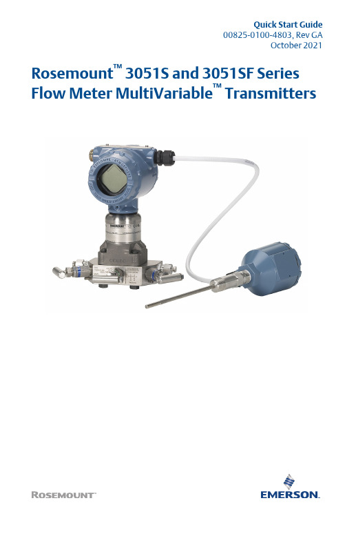
Quick Start Guide00825-0100-4803, Rev GAOctober 2021 Rosemount™ 3051S and 3051SF Series Flow Meter MultiVariable™ TransmittersQuick Start Guide October 2021 ContentsAbout this guide (3)Mount the transmitter (5)Consider housing rotation (11)Set the switches (12)Connect wiring and power up (13)Engineering Assistant installation (17)Flow configuration (19)Verifying device configuration (28)Trimming the transmitter (32)Safety instrumented systems installation (33)Product certifications (34)2Rosemount 3051SMVOctober 2021Quick Start Guide1About this guideThis guide provides basic guidelines to install the Rosemount 3051SMultiVariable Transmitter. It also provides the basic Rosemount 3051SMVconfiguration guidelines for the Rosemount 3051SFA, Rosemount 3051SFC,and Rosemount 3051SFP. It does not provide instructions for detailedconfiguration, diagnostics, maintenance, service, troubleshooting, orinstallations. Refer to the Rosemount 3051SMV Reference Manual for moreinstruction. The manual and this guide are also available electronically at/Rosemount.1.1Safety messagesWARNINGFailure to follow these installation guidelines could result in death orserious injury.Ensure only qualified personnel perform the installation.ExplosionsExplosions could result in death or serious injury.Installation of device in an explosive environment must be in accordancewith appropriate local, national, and international standards, codes, andpractices.Review the Hazardous Locations Certifications for any restrictionsassociated with a safe installation.Process leaksProcess leaks could result in death or serious injury.Install and tighten thermowells and sensors before applying pressure.Do not remove the thermowell while in operation.Conduit/cable entriesUnless marked, the conduit/cable entries in the transmitter housing usea ½–14 NPT thread form. Entries marked “M20” are M20 × 1.5 threadform. On devices with multiple conduit entries, all entries will have thesame thread form. Only use plugs, adapters, glands, or conduit with acompatible thread form when closing these entries.When installing in a hazardous location, use only appropriately listed orEx certified plugs, glands, or adapters in cable/conduit entries.Quick Start Guide3Quick Start Guide October 2021 WARNINGElectrical shockElectrical shock could cause death or serious injury.Avoid contact with the leads and terminals. High voltage that may bepresent on leads can cause electrical shock.Unless marked, the conduit/cable entries in the housing use a ½–14 NPTthread form. Entries marked “M20” are M20 × 1.5 thread form. Ondevices with multiple conduit entries, all entries will have the samethread form. Only use plugs, adapters, glands, or conduit with acompatible thread form when closing these entries.When installing in a hazardous location, use only appropriately listed orEx certified plugs, glands, or adapters in cable/conduit entries.Physical accessUnauthorized personnel may potentially cause significant damage to and/ormisconfiguration of end users’ equipment. This could be intentional orunintentional and needs to be protected against.Physical security is an important part of any security program andfundamental to protecting your system. Restrict physical access byunauthorized personnel to protect end users’ assets. This is true for allsystems used within the facility.4Rosemount 3051SMVOctober 2021Quick Start Guide 2Mount the transmitter2.1Liquid flow applicationsProcedure1.Place taps to the side of the line.2.Mount beside or below the taps.3.Mount the transmitter so that the drain/vent valves are orientedupward.AA. Direction of flow2.2Gas flow applicationsProcedure1.Place taps in the top or side of the line.Mount beside or above the taps.2.A. Direction of flowQuick Start Guide52.3Steam flow applicationsProcedure1.Place taps to the side of the line.2.Mount beside or below the taps.3.Fill impulse lines with water.AA. Direction of flow2.4Mounting bracketsFigure 2-1: Mounting Bracket – Coplanar FlangePanel mountPipe mountQuick Start Guide October 2021 6Rosemount 3051SMVFigure 2-2: Mounting Brackets – Traditional FlangePanel mountPipe mountFigure 2-3: Mounting Brackets – In-linePanel mountPipe mount2.5Bolting considerationsIf the transmitter installation requires assembly of a process flange,manifold, or flange adapters, follow these assembly guidelines to ensure atight seal for optimal performance characteristics of the transmitter. Onlyuse bolts supplied with the transmitter or sold by Emerson as spare parts.Figure 2-4 illustrates common transmitter assemblies with the bolt lengthrequired for proper transmitter assembly.October 2021Quick Start Guide Quick Start Guide7Figure 2-4: Common Transmitter AssembliesA 4 × 1.75-in.(44 mm)D4 × 1.75-in.(44 mm)4 × 2.25-in.(57 mm)C4 × 1.75-in. (44 mm) 4 × 1.50-in.(38 mm)4 × 2.88-in.(73 mm)A.Transmitter with coplanar flange B.Transmitter with coplanar flange and optional flange adapters C.Transmitter with traditional flange and optional flange adapters D.Transmitter with coplanar flange and optional Rosemount Conventional Manifold and flange adaptersNoteFor all other manifolds, contact Customer Central technical support.Bolts are typically carbon steel or stainless steel. Confirm the material byviewing the markings on the head of the bolt and referencing Table 2-1 . Ifbolt material is not shown in Table 2-1, contact the local Emersonrepresentative for more information.Use the following bolt installation procedure:Procedure1.Carbon steel bolts do not require lubrication and the stainless steelbolts are coated with a lubricant to ease installation. However, noadditional lubricant should be applied when installing either type ofbolt.2.Finger-tighten the bolts.3.Torque the bolts to the initial torque value using a crossing pattern.See Table 2-1 for initial torque value.4.Torque the bolts to the final torque value using the same crossing pattern. See Table 2-1 for final torque value.Quick Start Guide October 20218Rosemount 3051SMVOctober 2021Quick Start Guide5.Verify the flange bolts are protruding through the sensor modulebefore applying pressure (see Figure 2-5).ExampleTable 2-1: Torque Values for the Flange and Flange Adapter BoltsFigure 2-5: Proper Bolt InstallationA.BoltB.Sensor moduleQuick Start Guide92.6O-rings with flange adaptersWARNINGFailure to install proper flange adapter O-rings may cause process leaks,which can result in death or serious injury. Only use the O-ring that isdesigned for its specific flange adapter.DA.Flange adapterB.O-ring C.PTFE-based profile (square)D.Elastomer profile (round)Whenever the flange or adapters are removed, visually inspect the O-rings.Replace them if there are any signs of damage, such as nicks or cuts. If the O-rings are replaced, re-torque the flange bolts and alignment screws afterinstallation to compensate for seating of the O-rings.Quick Start Guide October 202110Rosemount 3051SMV3Consider housing rotationTo improve field access to wiring or to better view the optional LCD display:Procedure1.Loosen the housing rotation set screw.2.Turn the housing up to 180° left or right of its original (as shipped)position.3.Re-tighten the housing rotation set screw.Figure 3-1: Transmitter Housing Set ScrewA.LCD displayB.Housing rotation set screw (3/32-in.)CAUTIONDo not rotate the housing more than 180° without first performing adisassembly procedure. Over-rotation may sever the electricalconnection between the sensor module and the electronics.4Set the switchesThe transmitter’s default configuration sets the alarm condition to high (HI)and the security to off.Procedure1.If the transmitter is installed, secure the bus and remove power.2.Required: Remove the transmitter cover opposite the field terminalside. Do not remove the instrument covers in explosiveenvironments when the circuit is live.3.Slide the Security and Alarm switches into the preferred position byusing a small screwdriver.NoteThe Security switch will need to be in the off position in order to makeany configuration changes.4.Required: In order to meet explosion-proof requirements, reinstallthe housing cover and tighten so the cover is fully seated with metalto metal contact between the housing and cover. After the cover isseated properly, replace the flathead screw located on the bottom ofthe housing cover.Figure 4-1: Transmitter Switch ConfigurationA BA.SecurityB.AC Termination5Connect wiring and power upCAUTIONDo not connect the power across the test terminals. Power could damagethe test diode in the test connection. Twisted pairs yield best results. Use 24to 14 AWG wire and do not exceed 5,000 ft. (1500 m).Use the following steps to wire the transmitter:Procedure1.Remove the cover on the field terminals side of the housing.2.Connect the positive lead to the “PWR/COMM +” terminal, and thenegative lead to the “PWR/COMM –” terminal.3.If the optional process temperature input is not installed, plug andseal the unused conduit connection. If the input is being utilized, seeInstall optional process temperature input (Pt 100 RTD sensor) formore information.When the enclosed pipe plug is utilized in the conduit opening, itmust be installed with a minimum engagement of five threads tocomply with explosion-proof requirements. Refer to the Rosemount™3051SMV Reference Manual for more information.4.If applicable, install wiring with a drip loop. Arrange the drip loopso the bottom is lower than the conduit connections and thetransmitter housing.5.Reinstall the housing cover and tighten so that metal contacts metalto meet explosion-proof requirements.Figure 5-1 shows the wiring connections necessary to power aRosemount 3051SMV and enable communications with a hand-heldField Communicator.Figure 5-1: Transmitter WiringA. Power supplyNoteInstallation of the transient protection terminal block does notprovide transient protection unless the Rosemount 3051SMVhousing is properly grounded.5.1Conduit electrical connector wiring (option GE or GM)For Rosemount 3051SMV with conduit electrical connectors GE or GM, referto the cordset manufacturer’s installation instructions for wiring details. ForFM Intrinsically Safe, Division 2 hazardous locations, install in accordancewith Rosemount drawing 03151-1009 to maintain outdoor rating (NEMA®4X and IP66). See the Rosemount 3051SMV Reference Manual.5.2Power supplyThe dc power supply should provide power with less than two percent ripple.The total resistance load is the sum of the resistance of the signal leads andthe load resistance of the controller, indicator, intrinsic safety barriers, andrelated components.Figure 5-2: Load Limitation5.3Install optional process temperature input (Pt 100 RTDsensor)NoteTo meet ATEX/IECEx Flameproof certification, only ATEX/IECEx Flameproofcables (temperature input code C30, C32, C33, or C34) may be used.Procedure1.Mount the Pt 100 RTD sensor in the appropriate location.NoteUse shielded four-wire cable for the process temperatureconnection.2.Connect the RTD cable to the Rosemount 3051SMV by inserting thecable wires through the unused housing conduit and connect to thefour screws on the transmitter terminal block. An appropriate cablegland should be used to seal the conduit opening around the cable.3.Connect the RTD cable shield wire to the ground lug in the housing.Figure 5-3: RTD Wiring ConnectionA.Ground lugB.RTD cable assembly wiresC.Pt 100 RTD sensor6Engineering Assistant installationEngineering Assistant 6.1 or laterThe Rosemount 3051SMV Engineering Assistant 6.1 or later is PC-basedsoftware that performs configuration, maintenance, diagnostic functions,and serves as the primary communication interface to the transmitter withthe fully compensated mass and energy flow feature board.The Rosemount 3051SMV Engineering Assistant software is required tocomplete the flow configuration.To ensure correct operation, download the most current version of theEngineering Assistant software at /Rosemount-Engineering-Assistant.6.1System requirementsThe following are the minimum system requirements to install theRosemount 3051SMV Engineering Assistant software:•Pentium®-grade processor: 500 MHz or faster•Operating system: Windows™ XP Professional (32-bit), or Windows 7 (32-bit or 64-bit)•256 MB RAM•100 MB free hard disk space•RS232 serial port or USB port (for use with HART® modem)•CD-ROM6.2Install Rosemount 3051SMV Engineering Assistant 6.1 orlaterProcedure1.Uninstall any existing versions of Engineering Assistant 6.2.Insert the new Engineering Assistant disk into the CD-ROM.3.Windows should detect the presence of a CD and start theinstallation program. Follow the on-screen prompts to finish theinstallation. If Windows does not detect the CD, use WindowsExplorer or My Computer to view the contents of the CD-ROM, andthen double click the SETUP.EXE program.4. A series of screens (Installation Wizard) will appear and assist in theinstallation process. Follow the on-screen prompts. It isrecommended to use the default installation settings.NoteEngineering Assistant versions 6.1 or later require the use ofMicrosoft®.NET Framework version 4.0 or later. If .NET version 4.0 isnot currently installed, the software will be automatically installedduring the Engineering Assistant installation. Microsoft .NET version4.0 requires an additional 200 MB of disk space.6.3Connect to a personal computerProcedure1.Remove the cover from the field terminals side of the housing.2.Power the device as outlined in Connect wiring and power up.3.Connect the HART modem cable to the PC.4.On the side of the transmitter marked “Field Terminals,” connect themodem mini-grabbers to the two terminals marked “PWR/COMM.”unch the Engineering Assistant software. For more information onlaunching software, see Launch Engineering Assistant 6.1 or later.6.Once the configuration is complete, replace cover and tighten untilmetal contacts metal to meet explosion-proof requirements.Figure 6-1 shows how to connect a computer to a Rosemount3051SMV.Figure 6-1: Connecting a PC to the TransmitterA.Power supplyB.Modem7Flow configurationRosemount 3051SMV Engineering Assistant 6.1 or laterThe Rosemount 3051SMV Engineering Assistant is designed to guide theuser through the setup of the flow configuration for a Rosemount 3051SMV.The flow configuration screens allow the user to specify the fluid, operatingconditions, and information about the primary element, including insidepipe diameter. This information will be used by the Rosemount 3051SMVEngineering Assistant software to create flow configuration parameters thatwill be sent to the transmitter or saved for future use.Online and offline modesThe Engineering Assistant software can be used in two modes: Online andOffline. In Online mode, the user can receive the configuration from thetransmitter, edit the configuration, send the changed configuration to thetransmitter, or save the configuration to a file. In offline mode, the user cancreate a new flow configuration and save the configuration to a file or openand modify an existing file.The following pages provide instructions on creating a new flowconfiguration in offline mode. For more information on other functionality,see the Rosemount 3051SMV Reference Manual.7.1Basic navigation overviewFigure 7-1: Engineering Assistant Basic Navigation OverviewAFGHB C D E7.2Launch Engineering Assistant 6.1 or laterFlow configuration for the Rosemount 3051SMV is achieved by launchingthe Engineering Assistant software from the Start menu.Procedure1.Select the Start menu→All Programs→Engineering Assistant.Engineering Assistant will open to the screen shown in Figure 7-2.2.Select Offline button located in the lower right hand corner of thescreen shown in Figure 7-2.Figure 7-2: Engineering Assistant Device Connection Screen7.3Use Preferences tabThe Preferences tab, shown in Figure 7-3, allows you to select the preferredengineering units to display.Procedure1.Select the preferred engineering units.2.If Custom Units are selected, configure the Individual Parameters.3.Check the box if unit preferences should be retained for futureEngineering Assistant sessions.Figure 7-3: Preferences Tab7.4Select fluid for database liquid/gasThe Fluid Selection tab shown in Figure 7-4 allows the user to choose theprocess fluid.Figure 7-4: Fluid Selection TabNoteThe following example will show a flow configuration for the database gas air used with a Rosemount 405C Conditioning Orifice Plate as the primary element. The procedure to set up any other fluid with any other primary element will be similar to this example. Natural gases, custom liquids, and custom gases require additional steps during the configuration. See the Rosemount 3051SMV Reference Manual for more information. Procedure1.Engineering Assistant may open to the Preferences tab. Using the tabsat the top of the screen, navigate to the Fluid Selection tab.2.Expand the Gas category (click on the + icon).3.Expand the Database Gas category.4.Select Air from the list of database fluids.5.Enter the Nominal Operating Pressure, select the Enter or Tab key.6.Enter the Nominal Operating Temperature, select the Enter or Tab key.Engineering Assistant will automatically fill in suggested operatingranges, as shown in Figure 7-4. These values may be edited asneeded by the user.7.Verify the Reference/Atmospheric Conditions are correct for theapplication. These values may be edited as needed.NoteReference pressure and temperature values are used by EngineeringAssistant to convert the flow rate from mass units to mass unitsexpressed as standard or normal volumetric units.8.Select Next to proceed to the Fluid Properties tab.7.5Fluid propertiesNoteThe Fluid Properties tab is an optional step and is not required to complete aflow configuration.The Fluid Properties tab for the database gas air is shown in Figure 7-5. This isused to verify the properties of the chosen fluid are acceptable.To check density, compressibility, and viscosity of the selected fluid at otherpressure and temperature values, enter a Pressure and Temperature andselect Calculate.NoteChanging the pressure and temperature values on the Fluid Properties tabdoes not affect the fluid configuration.Figure 7-5: Fluid Properties Tab7.6Select primary elementThe Primary Element Selection tab shown in Figure 7-6 allows the user tochoose the primary element.Figure 7-6: Primary Element Selection TabContinuing with the example configuration:Procedure1.Expand the Conditioning Orifice Plate category.2.Select 405C/3051SFC.3.Enter the measured Meter Tube Diameter (pipe ID) at a referencetemperature. If the meter tube diameter cannot be measured, selecta Nominal Pipe Size and Pipe Schedule to input an estimated valuefor the meter tube diameter (English units only).4.If necessary, edit the Meter Tube Material.5.Enter the Line Size and select the Beta of the conditioning orificeplate. The required primary element sizing parameters will bedifferent depending on what primary element was selected.6.If necessary, select a primary element Material from the dropdownmenu.7.Select Next > to advance to the Save/Send Configuration tab.NoteTo be in compliance with appropriate national or internationalstandards, beta ratios and differential producer diameters should bewithin the limits as listed in the applicable standards. TheEngineering Assistant software will alert the user if a primary element value exceeds these limits, but will allow the user to proceed with the flow configuration.7.7Save/send configurationThe Save/Send Configuration tab shown in Figure 7-7 allows you to verify,save, and send the configuration information to the transmitter with thefully compensated mass and energy flow feature board.Procedure1.Review the information under the Flow Configuration and DeviceConfiguration headings.NoteFor more information, see Verifying device configuration.Figure 7-7: Save/Send Configuration Tab2.Select the icon above each window to edit the configurationinformation in these windows.NoteThe user will be notified if the configuration has been modified sinceit was last sent to the transmitter. A warning message will be shownto the right of the Send Flow Data and/or Send Transmitter Data checkboxes.3.To send the configuration, select the Send To button.NoteThe Send Flow Data and Send Transmitter Data check boxes can beused to select what configuration data is sent to the transmitter. Ifeither check box is unselected, the corresponding data will not besent.4.The Engineering Assistant Device Connection screen will appear, seeFigure 7-8.Figure 7-8: Engineering Assistant Device Connection Screen5.Select the Search button located in the lower right hand corner ofthe screen. Engineering Assistant will begin to search for connected devices.6.When the search is completed, select the device to communicatewith and select Send Configuration button.NoteAfter the configuration is sent to the device, saving the configuration file is recommended. The user can select the Save button on theSave/Send screen or select Save from the program menu.Once the configuration is finished being sent to the device, the user will be notified by a pop-up dialog box.7.If finished with the configuration process, close EngineeringAssistant.8Verifying device configurationUse Rosemount 3051SMV Engineering Assistant or any HART-compliantmaster to communicate with and verify configuration of the Rosemount3051SMV.Table 8-1 shows the Field Communicator fast keys for the fully compensatedmass and energy flow. Table 8-2 shows the Fast Keys for the direct processvariable output.NoteDevice configuration procedures are given for Rosemount 3051SMVEngineering Assistant 6.1 or later and AMS Device Manager 9.0 or later in theRosemount 3051SMV Reference Manual.A check (✓) indicates the basic configuration parameters. At a minimum,these parameters should be verified as part of the configuration and startupprocedure.Table 8-1: Fast Keys for Fully Compensated Mass and Energy FlowTable 8-2: Fast Keys for Direct Process Variable Output9Trimming the transmitterTransmitters are shipped fully calibrated per request or by the factorydefault of full scale.9.1Zero trimA zero trim is a single-point adjustment used for compensating mountingposition and line pressure effects on static and differential pressure sensors.When performing a zero trim, ensure that the equalizing valve is open andall wet legs are filled to the correct level.The transmitter will only allow up to five percent of URL zero error to betrimmed.9.1.1Perform a zero trim using the Field CommunicatorProcedure1.Equalize or vent the transmitter and connect the FieldCommunicator (for more information on connecting,see Figure 5-1).2.If the device is equipped with a static pressure sensor, zero the sensorby inputting the following Fast Key sequence at the Rosemount3051SMV menu:e the zero trim (selection 1) for a transmitter equipped with a gagestatic pressure sensor or lower sensor trim (selection 2) for atransmitted equipped with an absolute static pressure sensor.NoteWhen performing a lower sensor trim on an absolute pressuresensor, it is possible to degrade the performance of the sensor ifinaccurate calibration equipment is used. Use a barometer that is atleast three times as accurate as the absolute sensor of thetransmitter.4.Zero the differential pressure sensor by inputting the following FastKey sequence at the Rosemount 3051SMV menu:10Safety instrumented systems installation For safety certified installations, refer to the appropriate reference manualfor the installation procedure and system requirements:•For DP only measurements (measurement type D) refer to theRosemount 3051S Reference Manual.•For MultiVariable measurements (measurement type 1–7) refer to the Rosemount 3051SMV Reference Manual.11Product certifications11.1Rosemount 3051SMV/3051SFxRev 2.10European directive informationA copy of the EC Declaration of Conformity can be found at the end of theQuick Start Guide. The most recent revision of the EC Declaration ofConformity can be found at /Rosemount.Ordinary location certificationAs standard, the transmitter has been examined and tested to determinethat the design meets the basic electrical, mechanical, and fire protectionrequirements by a nationally recognized test laboratory (NRTL) as accreditedby the Federal Occupational Safety and Health Administration (OSHA).Installing Equipment in North AmericaThe US National Electrical Code (NEC) and the Canadian Electrical Code(CEC) permit the use of Division marked equipment in Zones and Zonemarked equipment in Divisions. The markings must be suitable for the areaclassification, gas, and temperature class. This information is clearly definedin the respective codes.11.1.1USAE5 US Explosionproof (XP) and Dust-Ignitionproof (DIP)Certificate FM16US0089XStandards FM Class 3600 – 2011, FM Class 3615 – 2006, FM Class 3616 –2011, FM Class 3810 – 2005, ANSI/NEMA 250 – 2003 Markings XP CL I, DIV 1, GP B, C, D; T5; DIP CL II, DIV 1, GP E, F, G; CL III;T5(–50 °C ≤ T a ≤ +85 °C); Factory Sealed; Type 4XI5 US Intrinsically Safe (IS) and Nonincendive (NI)Certificate FM16US0233Standards FM Class 3600 –2011, FM Class 3610 – 2007, FM Class 3611 –2004, FM Class 3616 – 2006, FM Class 3810 – 2005, NEMA250 – 1991Markings IS CL I, DIV 1, GP A, B, C, D; CL II, DIV 1, GP E, F, G; Class III; Class1, Zone 0 AEx ia IIC T4; NI CL 1, DIV 2, GP A, B, C, D; T4(–50 °C ≤T a ≤ +70 °C) when connected per Rosemount drawing03151-1206; Type 4XNoteTransmitters marked with NI CL 1, DIV 2 can be installed in Division 2locations using general Division 2 wiring methods or Nonincendive FieldWiring (NIFW). See Drawing 03151-1206.US Intrinsic Safety (IS) and Nonincendive (NI)Certificate:1143113Standards:FM Class 3600:2011, FM Class 3610:2010, FM Class3611:2004, FM Class 3810:2005, UL50E (1st Ed.)Markings:IS Class I/II/III, Division 1, Groups A, B, C, D, T4/ E, F, and GT135 °C; Class I, Zone 0 AEx ia IIC T4 Ga;T4 (-50 °C ≤ T a ≤ +70 °C) [HART];T4 (-50 °C ≤ T a ≤ +60 °C) [Fieldbus];when connected per Rosemount drawing 03151-1207; Type4XIE US FISCO Intrinsically SafeCertificate FM16US0233Standards FM Class 3600 – 2011, FM Class 3610 – 2010, FM Class 3611 –2004, FM Class 3616 – 2006, FM Class 3810 – 2005, NEMA250 – 1991Markings IS CL I, DIV 1, GP A, B, C, D; T4(–50 °C ≤ Ta ≤ +70 °C); whenconnected per Rosemount drawing 03151-1006; Type 4X US FISCO Intrinsically SafeCertificate:1143113Standards:FM Class 3600:2011, FM Class 3610:2010, FM Class3611:2004, FM Class 3810:2005, UL50E (1st Ed.)Markings:IS Class I/II/III, Division 1, Groups A, B, C, D, T4/ E, F, and GT135 °C; Class I, Zone 0 AEx ia IIC T4 Ga;T4 (-50 °C ≤ T a ≤ +70 °C) [HART];T4 (-50 °C ≤ T a ≤ +60 °C) [Fieldbus];when connected per Rosemount drawing 03151-1207; Type4X11.1.2CanadaE6 Canada Explosionproof, Dust Ignition-proof, Division 2Certificate1143113。
罗斯蒙特3051CG压力变送器关键参数

罗斯蒙特3051CG压力变送器(Rosemount 3051CG pressure transmitter)
型号:3051CG2A22A1AB4
总性能
+0.15 %量程,令回路性能更优化
参考精度
+0.065%量程,高精度选项可提升至+0.04%
稳定性
五年稳定性+0.125 %,可大大降低校验和维护费用
量程比100:1输出 Nhomakorabea叠加HART®数字信号通讯的4-20mA模拟信号;Foundation Fieldbus;Profibus
过压极限
3051CD/CG,量程2~5为31MPa;量程1为13.8MPa;3051T型高达103.4MPa。其它详见PDS。
静压极限
仅限3051CD型,3.5kPa-a~31MPa-g;对量程范围2~5,31MPa可选。详见PDS。
静压极限
仅限3051CD型,3.5kPa-a~31MPa-g;对量程范围2~5,31MPa可选。详见PDS。
电源
空载时工作在10.5~55V DC
重量
约3051C-3.1 kg;3051T-1.4kg,详见PDS。
尺寸
约198 x 126 x 104mm
危险场所认证
ATEX:防爆认证、本质安全认证
CSA:防爆认证、本质安全认证
型号:3051S1TG2A2E12A1AB4
Ultra超级型
Classic经典型
Ultra for Flow超级流量型
总性能
+0.1 %量程
+0.15 %量程
+0.1 %量程
参考精度
+0.025 %量程
罗斯蒙特变送器说明
重设量程 比例数模修正 (4–20 mA 输出 ) 自检 ( 变送器 ) 传感器信息 传感器温度 传感器修正点 状态
快键顺序 1, 4, 2, 7 1, 4, 3, 2, 4 1, 4, 3, 3, 3 1, 4, 3, 3, 4 1, 3, 7, 2 1, 4, 3, 4, 3 1, 3, 6 1, 3, 4, 1 1, 3, 4, 2 1, 2, 3, 2, 1 1, 4, 4, 1, 7 1, 4, 4, 1 1, 2, 3, 3 1, 2, 3, 1, 1 1, 4, 4, 1, 7 1, 2, 2 1, 2, 3, 3, 2 1, 3, 4, 3 1, 4, 3, 4 1, 4, 3, 3, 2 1, 4, 3, 3, 1 向左箭头 , 4, 1, 1 1, 3, 3 1, 2, 3, 1 1, 2, 3, 2, 2 1, 2, 1, 1 1, 4, 4, 2 1, 1, 4 1, 2, 3, 3, 5 1, 2, 1, 2
侧面或底部。 3. 将引压管内充满冷却水。
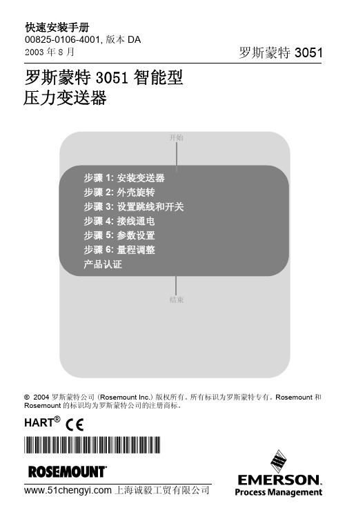
罗斯蒙特 3051
Flow
快速安装手册
00825-0106-4001, 版本 DA 2003 年 8 月
面板安装(1)
Coplanar 法兰
罗斯蒙特 3051
管道安装
Traditional 法兰
Rosemount 3051T Rosemount 3051H
(1) 面板的安装螺栓由用户自己提供。
快速安装手册
00825-0106-4001, 版本 DA 2003 年 8 月
罗斯蒙特 3051
步骤 2: 外壳旋转
通过外壳旋转以便改进现场的配线或能更好地观察 LCD 显示表头 :
1. 松开外壳上的旋转固定螺钉。 2. 首先按顺时针方向旋转外壳,2%。总的电阻负载等于信号线电阻,控制 仪、指示仪以及相关部件的负载电阻的总和。应注意,若使用本质安全 栅,则安全栅的电阻必须计入其中。
罗斯蒙特3051压力变送器产品数据表

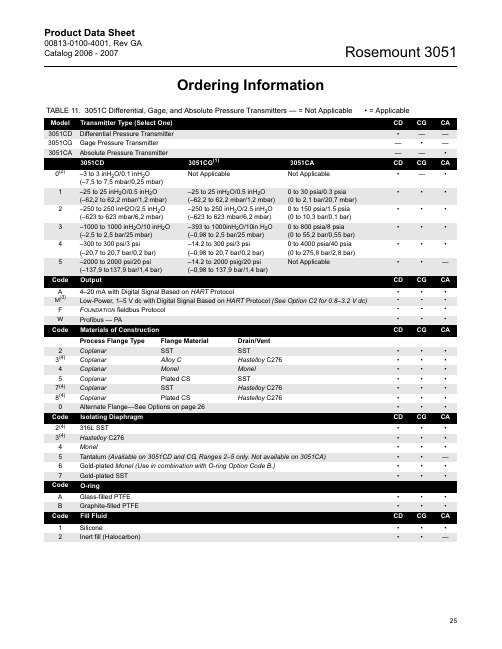
经实践检验的压力测量行业领袖·一流性能,参考精度高达 0.065%·量程比能力达100:1·共面™平台支持集成压力、流量和液位方案·整个 HART 产品系列通过了 IEC 61508 SIL2 级安全认证,可在遵从法规的同时简化您的工作 ·超过20年的向后兼容性使您在投资最新特性的同时不会增加工厂的复杂性·全球装机量超过 7 百万台罗斯蒙特 3051 压力变送器目录订购信息. . . . . . . . . . . . . . . . . . . . . . . . . . . . . . . . 第 2 页规格. . . . . . . . . . . . . . . . . . . . . . . . . . . . . . . . . . 第9 页产品认证. . . . . . . . . . . . . . . . . . . . . . . . . . . . . . . .第14 页尺寸图. . . . . . . . . . . . . . . . . . . . . . . . . . . . . . . . .第18页罗斯蒙特 3051D 共平面压力变送器其他信息规格:第9 页认证:第14 页尺寸图:第18 页表 1. 3051D 共平面压力变送器订购信息★ 标准产品表示最普通的选项。
为了实现快速交货,建议选择带星号的选项(★)。
对于扩展选项,交付周期需要另行商定。
型号变送器类型3051D共平面压力变送器测量类型标准标准P差压★G表压★压力范围3051DP3051DG标准标准1-6.216 kPa 至 6.216 kPa(–25 至 25 inH2O)-6.216 kPa 至 6.216 kPa(–25 至 25 inH2O)★2-62.1603 kPa 至 62.1603 kPa(–250 至 250 inH2O)-62.1603 kPa 至 62.1603 kPa(–250 至 250 inH2O)★3-248.641 kPa 至 248.641 kPa(–1000 至 1000 inH2O)-97.7159 kPa 至 248.641 kPa(–393 至 1000 inH2O)★4-2068.431 kPa 至 2068.431 kPa(–300 至 300 psi)-97.9057 kPa 至 2068.431 kPa(–14.2 至 300 psi)★5-13789.54 kPa 至 13789.54 kPa(–2000 至 2000 psi)-97.9057 kPa 至 13789.54 kPa(–14.2 至 2000 psi)★变送器输出标准标准A(1)4–20 mA,采用基于HART协议的数字信号★结构材料工艺法兰类型法兰材料排放/排气阀标准标准2共平面式316 不锈钢316 不锈钢★3(2)共平面式铸铁 C-276 合金 C-276★6共平面式304 不锈钢316 不锈钢★7(2)共平面式316 不锈钢合金 C-276★0备选工艺连接★3051D 共平面压力变送器2表 1. 3051D 共平面压力变送器订购信息★ 标准产品表示最普通的选项。
3051罗斯蒙特变送器手册
CD CG CA
S7 One Diaphragm Seal, All-Welded System (Capillary Connection Type) S8 Two Diaphragm Seals, All-Welded System (Capillary Connection Type) S0 One Diaphragm Seal, All-Welded System (Direct Mount Connection Type) S9 Two Diaphragm Seals, All-Welded System (One Direct Mount and One Capillary Connection Type)
•
•
•
•
•
—
25
Rosemount 3051
Product Data Sheet
00813-0100-4001, Rev GA Catalog 2006 - 2007
TABLE 11. 3051C Differential, Gage, and Absolute Pressure Transmitters — = Not Applicable • = Applicable
–1000 to 1000 inH2O/10 inH2O (–2,5 to 2,5 bar/25 mbar)
–300 to 300 psi/3 psi (–20,7 to 20,7 bar/0,2 bar)
–2000 to 2000 psi/20 psi (–137,9 to137,9 bar/1,4 bar)
CD CG CA
S1 One Diaphragm Seal (Direct Mount or Capillary Connection Type) S2 Two Diaphragm Seals (Direct Mount or Capillary Connection Type)
罗斯蒙特3051s差压液位变送器-产品说明书-中文

产品说明书00813-0106-4016, Rev UC2023 年 3 月Rosemount™差压液位变送器和 1199 远传密封件应用■液位、流量、压力、界面、密度■极热和极冷环境■腐蚀、堵塞或粘滞过程■卫生要求■特殊过程连接件成熟、可靠和创新的技术使用资产位号随时获取信息新发运设备包含一个唯一的二维码资产位号,您可以通过它直接从设备访问序列化信息。
通过此功能,您可以:■在您的 MyEmerson 账号上访问设备图纸、图表、技术文档和故障排除信息■优化维修和保持效率的平均时间■确保您定位了正确的设备■省去耗时的先定位和抄录铭牌再查看资产信息的工作罗斯蒙特液位变送器此液位变送器将世界先进的罗斯蒙特压力仪表与直接安装密封件相结合,全部集成为一个型号。
Rosemount 3051SAL、3051L 和 2051L型液位变送器■全焊接系统具备突出的系统可靠性■无线组态提供新数据访问■使用全面的过程连接产品、灌充液、直接安装或毛细管连接件和材料可连接到几乎任何过程■利用 QZ 选件量化和优化整个系统的性能内容成熟、可靠和创新的技术 (2)Rosemount 3051S 电子远程传感器 (ERS™) 系统 (6)Rosemount 3051S Scalable™液位变送器 (26)用于 Rosemount 3051SAL 的法兰密封件 (40)Rosemount 3051L 液位变送器订购信息 (65)Rosemount 2051L 液位变送器 (77)直接安装式密封系统订购信息 (86)远传安装式密封系统订购信息 (92)法兰密封件 (98)螺纹密封件 (123)卫生型密封件 (129)专业密封件 (144)技术规格 (153)产品认证 (173)尺寸图 (216)2023 年 3 月/Rosemount罗斯蒙特 Tuned-System ™ 组件优化结果罗斯蒙特 Tuned-System 组件在高压连接件上采用直接安装密封件,在低压连接件上则采用远程安装(毛细管式)密封件。
罗斯蒙特3051s压力变送器英文说明书

Product Data Sheet00813-0100-4801, Rev BA Catalog 2002 – 2003Model 3051S Series•Best-in-class performance with 0.02% high accuracy •Industry's first 10 year stability under actual process conditions•Unprecedented reliability backed by a limited lifetime warranty•SuperModule ™ design platform enables more cost effective installation and maintenance practices •Scalable functionality to meet your expanding needsContent“Specifications” . . . . . . . . . . . . . . . . . . . . . . . . . . . . . . . . . . . . . . . . . . . . . page Pressure-7“Hazardous Locations Certifications” . . . . . . . . . . . . . . . . . . . . . . . . . . . page Pressure-14“Dimensional Drawings” . . . . . . . . . . . . . . . . . . . . . . . . . . . . . . . . . . . . . page Pressure-16“Ordering Information”. . . . . . . . . . . . . . . . . . . . . . . . . . . . . . . . . . . . . . . page Pressure-24“Model 3051S HART Configuration Data Sheet”. . . . . . . . . . . . . . . . . . . page Pressure-36Model 3051S SeriesProduct Data Sheet00813-0100-4801, Rev BACatalog 2002 – 2003Model 3051S SeriesPressure-4Success goes beyond the transmitter to an enabling platformIntroducing the next evolution in measurement, the Model 3051S Series. This scalable platform enablesimplementation of the best measurement practices from design and installation to maintenance and operations.Best-in-class performance with 0.04% accuracy The Model 3051S delivers cutting edge performance beginning with the SuperModule platform. Among the many advances, Saturn ™ sensing technology incorporates a secondary sensor to optimize performance and expand diagnostic capabilities.Industry's first 10 year stability under actual process conditionsStability begins with an all-welded, 316L SSThermetically sealed SuperModule which houses the single board electronics, thus eliminating moisture and field contaminant effects.Unprecedented reliability backed by a limited lifetime warrantyThe SuperModule design delivers the most reliable platform to further enhance installation practices and advanced diagnostic capabilities.SuperModule design platform enables more cost effective installation and maintenance practices A scalable architecture enables direct mounting of the SuperModule for maximum performance and reliability. The flexible remote mount meter provides access to all digital communications and diagnostics.Scalable functionality to meet your expanding needsFrom basic process variable generation to advanced PlantWeb ™ functionality and highly integrated measurement solutions, the Model 3051S Series meets every application requirement.Rosemount ® Pressure SolutionsModel 3095MV Mass Flow TransmitterAccurately measures differential pressure, static pressure and process temperature to dynamically calculate fully compensated mass flow. See product data sheet 00813-0100-4716.Model 305 and 306 Integral Manifolds Factory-assembled, calibrated and seal-tested manifolds reduce on-site installation costs. See product data sheet 00813-0100-4733.Model 1199 Diaphragm SealsProvides reliable, remote measurements of process pressure and protects the transmitter from hot,corrosive, or viscous fluids. See product data sheet 00813-0100-4016.Model 1195 Integral Orifice andProPlate/Mass ProPlate FlowmetersConvenient ready-to-install assembly designed for small-bore flow measurement of any clean gas, liquid, or vapor. See product data sheet 00813-0100-4686.Annubar Flowmeter SeriesA series of highly accurate and repeatableinsertion-type flowmeters available in 2-in. to 72-in. (50.8 to 1829 mm) line sizes. See product data sheet 00813-0100-4809.Model 405P Compact OrificeA wafer style primary element with an integral three-valve manifold. See product data sheet00813-0100-4810.Product Data Sheet00813-0100-4801, Rev BA Catalog 2002 – 2003Pressure-5Model 3051S SeriesModel 3051S Selection GuideSELECT AN INSTRUMENT CONFIGURATIONModel 3051S_C Coplanar ™ Differential, Gage, and AbsoluteSee ordering information on page Pressure-24.•Performance up to 0.04% accuracy with 200:1 turndown •Available 10 year stability and limited lifetime warranty •Coplanar platform enables integrated manifold, primary element and diaphragm seal solutions •Calibrated spans from 0.1 inH 2O to 4000 psi (0,25 mbar to 276 bar)•316L SST, Hastelloy ® C, Monel ®, Tantalum, gold-plated Monel, or gold-plated 316L SST process isolatorsModel 3051S_T In-Line Gage and AbsoluteSee ordering information on page Pressure-28.•Performance up to 0.04% accuracy with 200:1 turndown•Available 10 year stability and limited lifetime warranty•Calibrated spans from 0.15 to 10000 psi (10,3 mbar to 689 bar)•Multiple process connections available •316L SST and Hastelloy C process isolatorsModel 3051S_L Liquid LevelSee ordering information on page Pressure-30.•Performance up to 0.065% accuracy with 100:1 turndown•Flush, 2-, 4-, and 6-in. extended diaphragms •Multiple fill fluids available•316L SST, Hastelloy, or Tantalum wetted materialsC O P L A N A R /3151_E 27BProduct Data Sheet00813-0100-4801, Rev BACatalog 2002 – 2003Model 3051S SeriesPressure-6CONSIDER PERFORMANCE REQUIREMENTS DETERMINE HOUSING AND PROCESS CONNECTIONUltraClassic•0.04% accuracy, 200:1 turndown•10 year stability and limited lifetime warranty•0.065% accuracy, 100:1 turndown •5 year stability••Product Data Sheet00813-0100-4801, Rev BA Catalog 2002 – 2003Pressure-7Model 3051S SeriesSpecificationsPERFORMANCE SPECIFICATIONSFor zero-based spans, reference conditions, silicone oil fill, SST materials, Coplanar flange (Model 3051S_C) or 1/2 in.- 18 NPT (Model 3051S_T) process connections, digital trim values set to equal range points.Conformance to specification (±3 Sigma)Technology leadership, advanced manufacturing techniques and statistical process control ensure specification conformance to at least ±3 sigma.Reference AccuracyTotal PerformanceLong Term StabilityUltra (1) (2)Classic (1)(2)Model 3051S_CD, CG±0.04% of span; for spans less than 10:1, accuracy =Range 1: ±0.09% of span;for spans less than 15:1, accuracy =Range 0: ±0.09% of span; for spans less than 2:1,accuracy= ±0.045% of URL±0.065% of span; for spans less than 10:1, accuracy =Range 1: ±0.10% of span;for spans less than 15:1, accuracy =Range 0: ±0.10% of span; for spans less than 2:1,accuracy= ±0.05% of URLModel 3051S_T±0.04% of span; for spans less than 10:1, accuracy =±0.065% of span; for spans less than 10:1, accuracy =Model 3051S_CA±0.04% of span; for spans less than 10:1, accuracy =Range 0: ±0.075% of span;for spans less than 5:1, accuracy =±0.065% of span; for spans less than 10:1, accuracy =Range 0: ±0.075% of span;for spans less than 5:1, accuracy =Model 3051S_LNot available±0.065% of span; for spans less than 10:1, accuracy =(1)Stated reference accuracy includes terminal based linearity, hysteresis, and repeatability.(2)For F OUNDATION fieldbus transmitters, use calibrated range in place of span.0.0050.0035+URLSpan ------------% of Span±0.0150.005+URLSpan ------------% of Span±0.0150.005+URLSpan ------------% of Span±0.0250.005+URLSpan ------------% of Span±0.004URLSpan ------------% of Span±0.0065URLSpan ------------% of Span±0.004URL Span ------------% of Span±0.0250.01+URL Span ------------% of Span±0.0065URL Span ------------% of Span±0.0250.01+URL Span ------------% of Span±0.0150.005+URL Span ------------% of Span±Ultra (1)Classic (1)Model 3051S_C CD Ranges 2-3 and CG Ranges 2-5±0.125% of span; for ±50°F (28°C) temperaturechanges, 0-100% relative humidity, up to 1000 psi (68,9 bar) line pressure (CD only), from 1:1 to 5:1 rangedown.±0.15% of span; for ±50°F (28°C) temperature changes, 0-100% relative humidity, up to 1000 psi (68,9 bar) line pressure (CD only), from 1:1 to 5:1 rangedown.(1)Total performance is based on combined errors of reference accuracy, ambient temperature effect, and line pressure effect.UltraClassicModel 3051S_C CD Ranges 2-3 and CG Ranges 2-5±0.20% of URL for 10 years; for ±50°F (28°C)temperature changes, 0-100% relative humidity, up to 1000 psi (68,9 bar) line pressure (CD only)±0.125% of URL for 5 years; for ±50°F (28°C)temperature changes, 0-100% relative humidity, up to 1000 psi (68,9 bar) line pressure (CD only)Product Data Sheet00813-0100-4801, Rev BACatalog 2002 – 2003Model 3051S SeriesPressure-8Dynamic PerformanceAmbient Temperature Effect per 50 °F (28 °C)Line Pressure Effect per 1000 psi (69 bar)For line pressures above 2000 psi (137,9 bar) and ranges 4-5, see the Model 3051S Series reference manual (document number 00809-0100-4801).Mounting Position EffectsUltraClassicModel 3051S_CD, CG± (0.009% URL + 0.04% span) from 1:1 to 10:1± (0.018% URL + 0.08% span) from 10:1 to 200:1Range 0: ± (0.25% URL + 0.05% span)Range 1: ± (0.1% URL + 0.25% span)± (0.0125% URL + 0.0625% span) from 1:1 to 5:1± (0.025% URL + 0.125% span) from 5:1 to 100:1Range 0: ± (0.25% URL + 0.05% span)Range 1: ± (0.1% URL + 0.25% span)Model 3051S_T± (0.0125% URL + 0.125% span) from 1:1 to 10:1± (0.025% URL + 0.125% span) from 10:1 to 200:1Range 1:± (0.025% URL + 0.125% span) from 1:1 to 10:1± (0.05% URL + 0.125% span) from 10:1 to 200:1Range 5: ± (0.1% URL + 0.15% span)± (0.025% URL + 0.125% span) from 1:1 to 30:1± (0.035% URL + 0.125% span) from 30:1 to 100:1Range 1:± (0.025% URL + 0.125% span) from 1:1 to 10:1± (0.05% URL + 0.125% span) from 10:1 to 100:1Range 5: ± (0.1% URL + 0.15% span)Model 3051S_CA± (0.025% URL + 0.125% span) from 1:1 to 30:1± (0.035% URL + 0.125% span) from 30:1 to 200:1Range 0: ± (0.1% URL + 0.25% span)± (0.025% URL + 0.125% span) from 1:1 to 30:1± (0.035% URL + 0.125% span) from 30:1 to 100:1Range 0: ± (0.1% URL + 0.25% span)Model 3051S_LNot availableSee Rosemount Instrument Toolkit ™UltraClassicModel 3051S_CDZero Error(1)± 0.035% of URL for line pressures from 0 to 2000 psi (0 to 137,9 bar)Range 0: ± 0.125% URL per 100 psi (6,89 bar)Range 1: ± 0.25% URLSpan Error± 0.1% of readingRange 0: ± 0.15% of reading per 100 psi (6,89 bar)Range 1: ± 0.4% of reading(1)Zero error can be calibrated outZero Error (1)± 0.05% URL for line pressures from 0 to 2000 psi (0 to 137,9 bar)Range 0: ± 0.125% URL per 100 psi (6,89 bar)Range 1: ± 0.25% URLSpan Error± 0.1% of readingRange 0: ± 0.15% of reading per 100 psi (6,89 bar)Range 1: ± 0.4% of readingUltra and ClassicModel 3051S_C Zero shifts up to ±1.25 inH 2O (3,11 mbar), which can be calibrated out; no span effectModel 3051S_LWith liquid level diaphragm in vertical plane, zero shift of up to 1 inH 2O (25,4 mmH 2O); with diaphragm in horizontal plane, zero shift of up to 5inH 2O (127 mmH 2O) plus extension length on extended units; all zero shifts can be calibrated out; no span effectModel 3051S_T and Model 3051S_CAZero shifts to 2.5 inH2O (63,5 mmH20), which can be calibrated out; no span effectProduct Data Sheet00813-0100-4801, Rev BA Catalog 2002 – 2003Pressure-9Model 3051S SeriesVibration EffectAll Models:Less than ±0.1% of URL when tested per the requirements of IEC60770-1 field or pipeline with high vibration level (10-60 Hz 0.21mm peak to peak displacement / 60-2000 Hz 3g).Option Codes 1J, 1K, 1LLess than ±0.1% of URL when tested per the requirements of IEC60770-1 field with general application or pipeline with low vibration level (10-60 Hz 0.15mm peak to peak displacement / 60-2000 Hz 2g).Power Supply EffectAll Models:Less than ±0.005% of calibrated span per voltRFI EffectsAll Models:±0.1% of span from 20 to 1000 MHz and for field strength up to 30 V/mTransient Protection (Option T1)All Models:Meets IEEE Standard 587, Category B1 kV crest (10 × 1000 microseconds)3 kV crest (8 × 20 microseconds)6 kV crest (12 × 50 microseconds)Meets IEEE Standard 472, Surge Withstand CapabilitySWC 2.5 kV crest, 1 MHz wave form General Specifications:Response Time: < 1 nanosecondPeak Surge Current: 5000 amps to housing Peak Transient Voltage: 100 V dc Loop Impedance: < 25 ohmsApplicable Standards: IEC 801-4, IEC 801-5NOTE:Calibrations at 68 °F (20 °C) per ASME Z210.1(ANSI)FUNCTIONAL SPECIFICATIONSRange and Sensor LimitsR a n g eMinimum Span 3051S_Range and Sensor Limits 3051S_Ultra Classic Upper (URL)Lower (LRL)Model 3051S_CD Model 3051S_CGModel 3051S_LD00.1 inH 2O (0,25 mbar)0.1 inH 2O (0,25 mbar) 3.0 inH 2O (7,5 mbar)–3.0 inH 2O (–7,5 mbar)NA NA 10.5 inH 2O (1,24 mbar)0.5 inH 2O (1,24 mbar)25.0 inH 2O (62,3 mbar)–25.0 inH 2O (–62,3 mbar)–25.0 inH 2O (–62,3 mbar)–25.0 inH 2O (–62,3 mbar)2 1.3 inH 2O (3,11 mbar) 2.5 inH 2O (6,23 mbar)250.0 inH 2O (0,62 bar)–250.0 inH 2O (–0,62 bar)–250.0 inH 2O (–0,62 bar) –250.0 inH 2O (–0,62 bar)3 5.0 inH 2O (12.4 mbar)10.0 inH 2O (24,9 mbar)1000.0 inH 2O (2,49 bar)–1000.0 inH 2O (-2,49 bar)0.5 psia (34,5 mbar)–1000.0 inH 2O (–2,49 bar)4 1.5 psi (103.4 mbar) 3.0 psi (206,8 mbar)300.0 psi (20,7 bar)–300.0 psi (–20,7 bar)0.5 psia (34,5 mbar)–300.0 psi (–20,7 bar)510.0 psi (689,5 mbar)20.0 psi (1,38 bar)2000.0 psi (137,9 bar)– 2000.0 psi (–137,9 bar)0.5 psia (34,5 mbar)– 2000.0 psi (–137,9 bar)Model 3051S_CA Range and Sensor LimitsMinimum SpanUpper (URL)Lower (LRL)Range UltraClassic00.167 psia (11,5 mbar)0.167 psia (11,5 mbar) 5 psia (0,34 bar)0 psia (0 bar) 10.3 psia (20,7 mbar)0.3 psia (20,7 mbar) 30 psia (2,07 bar) 0 psia (0 bar) 20.75 psia (51,7 mbar) 1.5 psia (0,103 bar) 150 psia (10,34 bar) 0 psia (0 bar) 3 4 psia (275,8 mbar)8 psia (0,55 bar) 800 psia (55,16 bar) 0 psia (0 bar) 420 psia (1,38 bar)40 psia (2,76 bar)4000 psia (275,8 bar)0 psia (0 bar)Product Data Sheet00813-0100-4801, Rev BACatalog 2002 – 2003Model 3051S SeriesPressure-10ServiceLiquid, gas, and vapor applications4–20 mA (output code A)Zero and Span AdjustmentZero and span values can be set anywhere within the range.Span must be greater than or equal to the minimum span.OutputTwo-wire 4–20 mA is user-selectable for linear or square root output. Digital process variable superimposed on 4–20 mA signal, available to any host that conforms to the HART protocol.Power SupplyExternal power supply required. Standard transmitter (4–20 mA) operates on 10.5 to 42.4 V dc with no load.Load LimitationsMaximum loop resistance is determined by the voltage level of the external power supply, as described by:F OUNDATION fieldbus (output code F)Power SupplyExternal power supply required; transmitters operate on 9.0 to 32.0 V dc transmitter terminal voltage.Current Draw17.5 mA for all configurations (including LCD meter option)Overpressure LimitsTransmitters withstand the following limits without damage:Model 3051S_CD, CG Range 0: 750 psi (51,7 bar)Range 1: 2000 psig (137,9 bar)Ranges 2–5: 3626 psig (250,0 bar)4500 psig (310,3 bar) for Option Code P9Model 3051S_CARange 0: 60 psia (4,13 bar)Range 1: 750 psia (51,7 bar)Range 2: 1500 psia (103,4 bar)Range 3: 1600 psia (110,3 bar)Range 4: 6000 psia (413,7 bar)Model 3051S_TG, TA Range 1: 750 psi (51,7 bar)Range 2: 1500 psi (103,4 bar)Range 3: 1600 psi (110,3 bar)Range 4: 6000 psi (413,7 bar)Range 5: 15000 psi (1034,2 bar)Model 3051S_LD, LGLimit is 0 psia to the flange rating or sensor rating, whichever is lower (see the table below).Static Pressure LimitModel 3051S_CD OnlyOperates within specifications between static line pressures of 0.5 psia and 3626 psig;4500 psig (310,3 bar) for Option Code P9Range 0: 0.5 psia to 750 psig (0,03 to 51,71 bar)Range 1: 0.5 psia to 2000 psig (0,03 to137,90 bar)Model 3051S_T Range and Sensor LimitsRange Minimum SpanUpper (URL)Lower (LRL) (Abs.)Lower (1) (LRL) (Gage)UltraClassic 10.15 psi (10,3 mbar)0.3 psi (20,7 mbar)30 psi (2,07 bar)0 psia (0 bar)–14.7 psig (–1,01 bar)20.75 psi (51,7 mbar) 1.5 psi (0,103 bar)150 psi (10,34 bar)0 psia (0 bar)–14.7 psig (–1,01 bar)3 4 psi (275,8 mbar)8 psi (0,55 bar)800 psi (55,16 bar)0 psia (0 bar)–14.7 psig (–1,01 bar)420 psi (1,38 bar)40 psi (2,76 bar)4000 psi (275,8 bar)0 psia (0 bar)–14.7 psig (–1,01 bar)51000 psi (68,9 bar)2000 psi (137,9 bar)10000 psi (689,5 bar)0 psia (0 bar)–14.7 psig (–1,01 bar)(1)Assumes atmospheric pressure of 14.7 psig.L o a d (O h m s )Communication requires a minimum loop resistance of 250 ohms.Max. Loop Resistance = 43.5 (Power Supply Voltage – 10.5)StandardTypeCS RatingSST RatingANSI/ASME Class 150285 psig 275 psig ANSI/ASME Class 300740 psig 720 psig ANSI/ASME Class 6001480 psig 1440 psigAt 100 °F (38 °C), the rating decreaseswith increasing temperature.DIN PN 10–4040 bar 40 bar DIN PN 10/1616 bar 16 bar DIN PN 25/4040 bar 40 barAt 248 °F (120 °C), the rating decreaseswith increasing temperature.Product Data Sheet00813-0100-4801, Rev BA Catalog 2002 – 2003Pressure-11Model 3051S SeriesBurst Pressure LimitsBurst pressure on Coplanar or traditional process flange is 10000 psig (689,5 bar).Burst pressure for the Model 3051S_T is:Ranges 1–4: 11000 psi (758,4 bar)Range 5: 26000 psig (1792,64 bar)Temperature LimitsAmbient–40 to 185 °F (–40 to 85 °C)With integral meter: –4 to 175 °F (–20 to 80 °C)Storage–50 to 230 °F (–46 to 110 °C)With integral meter: –40 to 185 °F (–40 to 85 °C)Process Temperature Limits At atmospheric pressures and above.Humidity Limits0–100% relative humidityTurn-On TimePerformance within specifications less than 2.0 seconds after power is applied to the transmitterVolumetric DisplacementLess than 0.005 in 3 (0,08 cm 3)DampingAnalog output response to a step input change is user-selectable from 0 to 60 seconds for one time constant. This software damping is in addition to sensor module response time.Failure Mode AlarmHART 4-20mA (output code A)If self-diagnostics detect a gross transmitter failure, the analog signal will be driven offscale to alert the user. Rosemount standard, NAMUR, and custom alarm levels are available (see Table 1 below).High or low alarm signal is software-selectable orhardware-selectable via the optional switch (option D1).F OUNDATION Fieldbus (output code F)The AI block allows the user to configure HI-HI, HI, LO, or LO-LO, alarms.PHYSICAL SPECIFICATIONSElectrical Connections1/2–14 NPT, G 1/2, and M20 × 1.5 (CM20) conduit. HART interface connections fixed to terminal block for output code A.Process ConnectionsModel 3051S_C1/4–18 NPT on 21/8-in. centers1/2–14 NPT and RC 1/2 on 2 in.(50.8mm), 21/8 in. (54.0 mm), or 21/4-in. (57.2mm) centers (process adapters)Model 3051S_T1/2–14 NPT female, Non-Threaded instrument flange(available in SST for Range 1–4 transmitters only), G 1/2 A DIN 16288 Male (available in SST for Range 1–4 transmitters only), or Autoclave type F-250-C (Pressure relieved 9/16–18 gland thread; 1/4 OD high pressure tube 60° cone; available in SST for Range 5 transmitters only).Model 3051S_C CoplanarSilicone Fill Sensor (1)(1)Process temperatures above 185 °F (85 °C) require derating theambient limits by a 1.5:1 ratio.with Coplanar Flange –40 to 250 °F (–40 to 121 °C)(2)(2)220 °F (104 °C) limit in vacuum service; 130 °F (54 °C) forpressures below 0.5 psia.with Traditional Flange –40 to 300 °F (–40 to 149 °C)(2)with Level Flange–40 to 300 °F (–40 to 149 °C)(2)with Model 305 Integral Manifold–40 to 300 °F (–40 to 149 °C)(2)Inert Fill Sensor (1)0 to 185 °F (–18 to 85 °C)(3)(4)(3)160 °F (71 °C) limit in vacuum service.(4)Not available for Model 3051S_CA.Model 3051S_T In-Line (Process Fill Fluid)Silicone Fill Sensor (1)–40 to 250 °F (–40 to 121 °C)(2)Inert Fill Sensor (1)–22 to 250 °F (–30 to 121 °C)(2)Model 3051S_L Low-Side Temperature Limits Silicone Fill Sensor (1)–40 to 250 °F (–40 to 121 °C)(2)Inert Fill Sensor (1)0 to 185 °F (–18 to 85 °C)(2)Model 3051S_L High-Side Temperature Limits(Process Fill Fluid)Syltherm ®XLT–100 to 300 °F (–73 to 149 °C)D.C.® Silicone 704(5)(5)Upper limit of 600 °F (315 °C) is available with Model 1199 sealassemblies mounted away from the transmitter with the use of capillaries and up to 500 °F (260 °C) with direct mount extension.60 to 400 °F (15 to 205 °C)D.C. Silicone 200–40 to 400 °F (–40 to 205 °C)Inert–50 to 350 °F (–45 to 177 °C)Glycerin and Water 0 to 200 °F (–18 to 93 °C)Neobee M-20®0 to 400 °F (–18 to 205 °C)Propylene Glycol and Water0 to 200 °F (–18 to 93 °C)TABLE 1. Alarm ConfigurationHigh AlarmLow Alarm Rosemount≥ 21.75 mA ≤ 3.75 mA NAMUR compliant (1)(1)Analog output levels are compliant with NAMUR recommendationNE 43 (June 27, 1996)≥ 22.5 mA ≤ 3.6 mA Custom levels (2)(2)Low alarm must be 0.1 mA less than low saturation and high alarmmust be 0.1 mA greater than high saturation.20.2 - 23.0 mA3.6 - 3.8 mAProduct Data Sheet00813-0100-4801, Rev BACatalog 2002 – 2003Model 3051S SeriesPressure-12Model 3051S_LHigh pressure side: 2 in.(50.8mm), 3 in. (72 mm), or 4-in.(102mm), ASME B 16.5 (ANSI) Class 150, 300 or 600 flange; 50, 80 or 100 mm, DIN 2501 PN 40 or 10/16 flange Low pressure side: 1/4–18 NPT on flange 1/2–14 NPT on process adapterProcess-Wetted PartsProcess Isolating DiaphragmsDrain/Vent Valves316 SST, Hastelloy C-276, or Monel 400 material (Monel is not available with Model 3051S_L.)Process Flanges and AdaptersPlated carbon steel, CF-8M (Cast version of 316 SST, material per ASTM-A743), CW-12MW (Cast version of Hastelloy C-276, material per ASTM A494), M-30C (Cast version of Monel 400, material per ASTM A494).Wetted O-ringsGlass-filled TFE(Graphite-filled TFE with isolating diaphragm Option Code 6)Model 3051S_L Process Wetted PartsFlanged Process Connection (Transmitter High Side)Process Diaphragms, Including Process Gasket Surface 316L SST, Hastelloy C-276, or Tantalum ExtensionCF-3M (Cast version of 316L SST, material per ASTM-A743), or CW-12MW (Cast version of Hastelloy C, material ASTM A494); fits schedule 40 and 80 pipe Mounting FlangeZinc-cobalt plated CS or 316 SSTReference Process Connection (Transmitter Low Side)Isolating Diaphragms 316L SST or Hastelloy C-276Reference Flange and AdapterCF-3M (Cast version of 316L SST, material per ASTM-A743)Non-Wetted PartsElectronics HousingLow-copper aluminum or CF-3M (Cast version of 316L SST) NEMA 4X, IP 65, IP 66Coplanar Sensor Module Housing CF-3M (Cast version of 316L SST)BoltsPlated carbon steel per ASTM A449, Type 1: Austenitic 316 SST, ASME B 16.5 (ANSI)/ASTM-A-193-B7M, or Monel Sensor Module Fill FluidSilicone or inert halocarbon (Inert is not available with Model 3051S_CA.) In-Line series uses Fluorinert ® FC-43Process Fill Fluid (Liquid Level Only)Model 3051S_L: Syltherm XLT, D.C. Silicone 704, D.C. Silicone 200, inert, glycerin and water, Neobee M-20, propylene glycol and water Paint Polyurethane Cover O-rings Buna-NOrdinary Locations CertificationsAs standard, the transmitter has been examined and tested to determine that the design meets basic electrical, mechanical, and fire protection requirements by FM, a nationally recognized testing laboratory (NRTL) as accredited by the Federal Occupational Safety and Health Administration (OSHA).Isolating Diaphragm Material Model 3051S_CD, CG T CA L 316L SST•••S e e B e l o wHastelloy C-276 ®•••Monel 400••Tantalum•Gold-plated Monel 400••Gold-plated 316L SST ••Shipping Weights for Model 3051S TABLE 2. SuperModule weightsTABLE 3. Transmitter weights without optionsTABLE 4. Model 3051S_L weights without optionsTABLE 5. Transmitter option weightsSuperModule Weight in lb. (kg)Coplanar (1)(1)Flange and bolts not included.3.1 (1,4)In-Line1.4 (0,64)Complete Transmitter (1)(1)Fully functional transmitter with terminal block,covers, and SST flange.Add Weight In lb (kg)Model 3051S_C with junction box housing 6.9 (3,1)Model 3051S_T with junction box housing 3.3 (1,5)Model 3051S_C with PlantWeb housing 7.2 (3,3)Model 3051S_T with PlantWeb housing3.6 (1,6)FlangeFlush lb. (kg)2-in. Ext.lb (kg)4-in. Ext.lb (kg)6-in. Ext.lb (kg)2-in., 15012.5 (5,7)———3-in., 15017.5 (7,9)19.5 (8,8)20.5 (9,3)21.5 (9,7)4-in., 15023.5 (10,7)26.5 (12,0)28.5 (12,9)30.5 (13,8)2-in., 30017.5 (7,9)———3-in., 30022.5 (10,2)24.5 (11,1)25.5 (11,6)26.5 (12,0)4-in., 30032.5 (14,7)35.5 (16,1)37.5 (17,0)39.5 (17,9)2-in., 60015.3 (6,9)———3-in., 60025.2 (11,4)27.2 (12,3)28.2 (12,8)29.2 (13,2)DN 50 / PN 4013.8 (6,2)———DN 80 / PN 4019.5 (8,8)21.5 (9,7)22.5 (10,2)23.5 (10,6)DN 100 / PN 10/1617.8 (8,1)19.8 (9,0)20.8 (9,5)21.8 (9,9)DN 100 / PN 4023.2 (10,5)25.2 (11,5)26.2 (11,9)27.2 (12,3)Code OptionAdd lb (kg)1J, 1K, 1L SST PlantWeb housing3.4 (1,5)2A, 2B, 2C Aluminum Junction Box housing 1.2 (5,4)1A, 1B, 1C Aluminum PlantWeb housing1.2 (5,4)M5LCD meter for aluminum PlantWeb housing (1),LCD meter for SST PlantWeb housing (1)0.8 (0,4)1.72 (0,8)B4SST mounting bracket for Coplanar flange 0.6 (0,3)B1, B2, B3Mounting Bracket for Traditional flange2.3 (1,0)B7, B8, B9Mounting Bracket for Traditional flange with SST bolts 2.3 (1,0)BA, BC SST Bracket for Traditional flange 2.3 (1,0)F12, F22SST Traditional flange (2)3.3 (1,5)F13, F23Traditional flange (Hastelloy) 2.7 (1,2)E12, E22SST Coplanar flange (2) 1.9 (8,6)F14, F24Traditional flange (Monel)2.6 (1,2)F15, F25Traditional Flange (SST with Hastelloy D/V) 2.5 (1,1)G21Level flange—3 in., 15010.8 (4,9)G22Level flange—3 in., 30014.3 (6,5)G11Level flange—2 in., 15010.7 (4,8)G12Level flange—2 in., 30014.0 (6,3)G31DIN Level flange, SST, DN 50, PN 408.3 (3,8)G41DIN Level flange, SST, DN 80, PN 4013.7 (6,2)(1)Includes LCD meter connector board and meter cover (2)Includes mounting boltsItemWeight In lb. (kg)Aluminum standard cover 0.4 (0,2)SST standard cover 1.26 (0,6)Aluminum meter cover 0.7 (0,3)SST meter cover 1.56 (0,7)LCD meter (1)0.1 (0,1)Junction Box terminal block 0.3 (0,2)PlantWeb terminal block0.2 (0,1)Hazardous Locations CertificationsFactory Mutual (FM) ApprovalsE5Explosion proof for Class I, Division 1, Groups B, C, and D;dust-ignition proof for Class II and Class III, Division 1,Groups E, F, and G; hazardous locations;enclosure Type 4X, conduit seal not required when installed according to Rosemount drawing 03151-1003.I5/IE Intrinsically Safe for use in Class I, Division 1, Groups A, B, C, and D; Class II, Division 1, Groups E, F, and G; Class III, Division 1 when connected in accordance with Rosemountdrawing 03151-1006; Temperature Code T4; Non-incendive for Class I, Division 2, Groups A, B, C, and D), EnclosureType 4XFor entity parameters see control drawing 03151-1006.CENELEC/BASEEFA ApprovalsI1/ IA Intrinsic SafetyCertificate No. BAS01ATEX1303XATEX Marking: II 1GI1EEx ia IIC T5 (-60°C ≤Ta ≤40°C)T4 (-60°C ≤Ta ≤70°C)IA EEx ia IIC T4 (-60°C ≤Ta ≤40°C)Input Parameters (IA)Ui = 15VIi = 215mA (IIC) Pi = 2W (IIC)Ii = 0.5A (IIB) Pi = 5.32W (IIB)Ci = 0 Li = 0SPECIAL CONDITIONS FOR SAFE USE (X):The apparatus with transient protection is not capable of withstanding the 500V test defined in Clause 6.4.12 of EN50 020. This must be considered during installation.The terminal pins of the Model 3051S must be protected to IP20 minimum.N1Non-incendiveCertificate No. BAS01ATEX3304XATEX Marking: II 3 GEEx nL IICND DustCertificate No. BAS01ATEX1374XATEX Marking: II 1 D T105°C (Ta 85°C)IP66SPECIAL CONDITIONS FOR SAFE USE (X):1. The user must ensure that the maximum rated voltage and current (42.2 volts, 22 milliamps, DC) are not exceeded. All connections to other apparatus or associated apparatus shall have control over this voltage and current equivalent to a category “ib” circuit according to EN50020.2. Cable entries must be used which maintain the ingress protection of the enclosure to at least IP66.3. Unused cable entries must be filled with suitable blanking plugs which maintain the ingress protection of the enclosure to at least IP66.4. Cable entries and blanking plugs must be suitable for the ambient range of the apparatus and capable of withstanding a 7J impact test.5. The 3051S must be securely screwed into a Housing to maintain the ingress protection of the enclosure.KEMA/CENELEC Flameproof CertificationCertificate No. KEMA 00ATEX 1243XATEX Marking: II 1/2 GE1EEx d IIC T6 (T amb = 65 °C);EEx d IIC T5 (T amb = 80 °C)SPECIAL CONDITIONS FOR SAFE USEThis device contains a thin wall diaphragm. Installation, maintenance and use shall take into account the environmental conditions to which the diaphragm will be subjected. The manufacturer’s instructions for installation and maintenance shall be followed in detail to assure safety during its expected lifetime. The Model 3051S pressure transmitter must include a Series 300S housing integrally mounted to a Series Model 3051S Sensor module as per Rosemount drawing 0351-1023.Input Parameters (I1)GroupsUi = 30V HART/4—20mAIi = 300 mA HART/4—20mAPi = 1.0W HART/4—20mAPi = 1.3W with output F or WCi = 30nFCi = 11.4nF with a Housing option Li = 0。
罗斯蒙特变送器
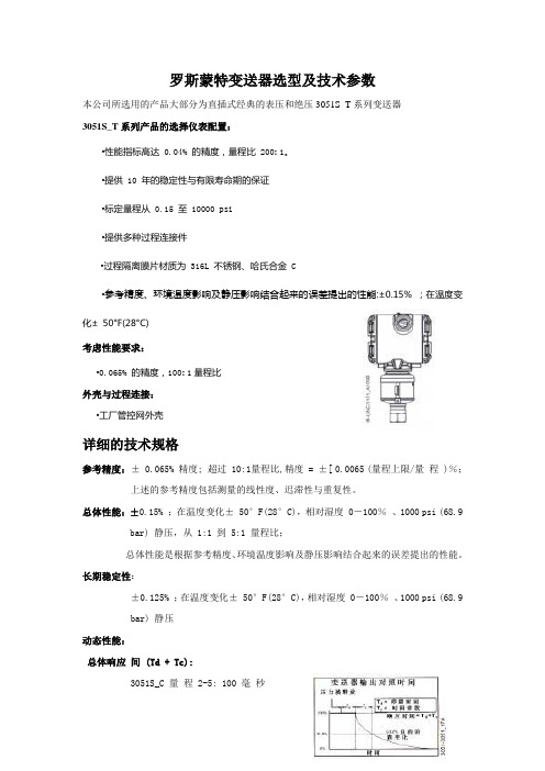
罗斯蒙特变送器选型及技术参数本公司所选用的产品大部分为直插式经典的表压和绝压3051S_T系列变送器3051S_T系列产品的选择仪表配置:•性能指标高达 0.04% 的精度,量程比 200: 1。
•提供 10 年的稳定性与有限寿命期的保证•标定量程从 0.15 至 10000 psi•提供多种过程连接件•过程隔离膜片材质为 316L 不锈钢、哈氏合金 C•参考精度、环境温度影响及静压影响结合起来的误差提出的性能:±0.15% ;在温度变化±50°F(28°C)考虑性能要求:•0.065% 的精度,100: 1量程比外壳与过程连接:•工厂管控网外壳详细的技术规格参考精度:± 0.065% 精度; 超过 10:1量程比,精度 = ±[ 0.0065 (量程上限/量程 )%;上述的参考精度包括测量的线性度、迟滞性与重复性。
总体性能:±0.15% ;在温度变化± 50°F(28°C),相对湿度 0-100%、1000 psi (68.9 bar) 静压,从 1:1 到 5:1 量程比;总体性能是根据参考精度、环境温度影响及静压影响结合起来的误差提出的性能。
长期稳定性:±0.125% ;在温度变化± 50°F(28°C),相对湿度 0-100%、1000 psi (68.9bar) 静压动态性能:总体响应间 (Td + Tc):3051S_C 量程 2-5: 100 毫秒量程 1: 255 毫秒量程 0: 700 毫秒3051S_T: 100 毫秒停滞时间 (Td ):45 毫秒更新速率:22次/秒环境温度每变化 50°F (28°C) 的影响:±(0.025 %量程上限+ 0.125% 量程), 1:1至 30:1 ±(0.035 %量程上限+ 0.125% 量程), 30:1至100:1 量程1: ±(0.025 %量程上限+ 0.125% 量程), 1:1至10:1 ±(0.05 %量程上限+ 0.125% 量程), 10:1至100:1 量程5: ±(0.1% 量程上限+ 0.15% 量程)静压每变化1000 psi (69 bar) 的影响:零点误差静压由 0 至 2000psi 误差为±0.05%量程 0: 每变化100psi 误差为±0.125%量程1: ±0.25%满量程误差±0.1%量程 0: 每变化100psi 误差±0.15%量程1: ±0.4%安装位置的影响:零漂最高为 2.5 英寸水柱 , 可标定抵消掉 ; 对量程无影响振动影响所有型号:误差小于量程上限的±0.1% ,选项代码 1J 、1K 、1L,误差小于量程上限的±0.1% 。
罗斯蒙特3051压力变送器产品说明书

产品说明书00813-0106-4001, Rev WE2023 年 4 月Rosemount™ 3051 压力变送器通过 Rosemount 3051 压力变送器,您将更有效地控制工厂,能够在众多压力、液位和流量应用中借助我们的产品,减少产品变化和复杂性,降低总拥有成本。
您将可以访问各种信息,方便您进行诊断、校正甚至防止出现问题。
以我们无与伦比的可靠性和丰富的经验打造的 Rosemount 3051 符合行业标准,可帮助您以更高的效率和安全性标准进行工作,从而保持全球竞争力。
Rosemount 30512023 年 4 月内容建立压力测量标准 (2)Rosemount 3051C 共平面压力变送器订购信息 (6)Rosemount 3051T 直连式变送器订购信息 (18)Rosemount 3051CF 流量计选择指南 (28)Rosemount 3051L 液位变送器订购信息 (62)技术规格 (74)Rosemount 3051 产品认证 (91)尺寸图 (92)选项外, (106)建立压力测量标准经实践检验的一流性能、可靠性和安全性■超千万装机量■参考精度为量程的 0.04%■安装总性能为量程的 0.14%■稳定性可保持在 URL 的 0.1% 长达 12 年■SIL 2/3 认证(IEC 61508)Coplanar ™平台增强安装和应用灵活性■通过集成的差压流量计、差压液位解决方案和一体化阀组提高可靠性和性能。
■安装方便,所有方案都全面组合,并经过渗漏测试和标定。
■丰富的产品满足您的应用需求。
高级功能Bluetooth ® 技术■提高生产力、可靠性和人员安全性。
无需高温作业许可。
无需攀爬储罐或建筑脚手架。
■快速组态、检修和排除故障,所有设备对技术人员触手可及,速度比传统 HART ® 连接快十倍。
诊断■回路完整性诊断将连续地监测电路,检测影响通讯信号的问题,并提供腐蚀、外罩进水或电源不稳定等警报。
罗斯蒙特3051测量变送器和3051CF流量计快速安装指南 (Rev KA)说明书

Kurzanleitung00825-0105-4774, Rev KAJanuar 2020 Rosemount™ 3051 Druckmessumformer und Rosemount Durchflussmessgerät der Serie 3051CFmit F OUNDATION™ Feldbus-ProtokollKurzanleitung Januar 2020SicherheitshinweiseVor dem Installieren des Messumformers prüfen, ob der richtige Gerätetreiber (DD) in denHostsystemen geladen ist. Siehe Systembereitschaft.Die in diesem Abschnitt beschriebenen Anleitungen und Verfahren können besondereVorsichtsmaßnahmen erforderlich machen, um die Sicherheit des Bedienpersonals zu gewährleisten.Diese Kurzanleitung enthält grundlegende Richtlinien für Rosemount 3051 Messumformer. Sie enthält keine Anweisungen für Konfiguration, Diagnose, Wartung, Service, Störungsanalyse und -beseitigung oder Einbau entsprechend den Anforderungen für Ex-Schutz, druckfeste Kapselung oderEigensicherheit. Weitere Informationen sind in der Betriebsanleitung für den Rosemount 3051 zufinden. Diese Anleitung ist auch in elektronischer Ausführung unter /Rosemounterhältlich.WARNUNGExplosionenExplosionen können zu schweren oder tödlichen Verletzungen führen.Die Installation dieses Messumformers in explosionsgefährdeten Umgebungen mussentsprechend den lokalen, nationalen und internationalen Normen, Vorschriften undEmpfehlungen erfolgen. Jegliche Einschränkungen in Verbindung mit der sicheren Installationüberprüfen.Einschränkungen in Verbindung mit der sicheren Installation sind im AbschnittProdukt-Zulassungen im Produktdatenblatt des Rosemount 3051 zu finden.Vor Anschluss eines Handterminals in einer explosionsgefährdeten Umgebung sicherstellen, dassdie Geräte im Messkreis in Übereinstimmung mit den Vorschriften für eigensichere oder keineFunken erzeugende Feldverkabelung installiert sind.Bei einer Installation mit Ex-Schutz/druckfester Kapselung die Messumformer Gehäusedeckelnicht entfernen, wenn der Stromkreis unter Spannung steht.ProzessleckagenProzessleckagen können zu schweren oder tödlichen Verletzungen führen.Prozesslecks könnenschwere oder tödliche Verletzungen verursachen.Prozesslecks können schwere oder tödlicheVerletzungen verursachen.Vor der Druckbeaufschlagung müssen die Prozessanschlüsse installiert und fest angezogenwerden.Um Prozesslecks zu vermeiden, nur den vorgeschriebenen O-Ring verwenden, der denentsprechenden Flanschadapter abdichtet.StromschlagElektrische Schläge können schwere oder tödliche Verletzungen verursachen.Elektrische Schlägekönnen schwere oder tödliche Verletzungen verursachen.Elektrische Schläge können schwere odertödliche Verletzungen verursachen.Kontakt mit Leitungsadern und Anschlussklemmen meiden. Elektrische Spannung an denLeitungsadern kann zu elektrischen Schlägen führen.Elektrostatische AufladungEmpfindliche Komponenten können durch statische Elektrizität beschädigt werden.Die entsprechenden Handhabungsvorschriften für statisch empfindliche Komponenten befolgen.2Rosemount 3051Januar 2020Kurzanleitung WARNUNGLeitungseinführungenFalls nicht anderweitig markiert, haben die Leitungseinführungen im Messumformergehäuse ein ½-14-NPT-Gewinde. Die Angabe …M20“ bezieht sich auf Gewinde der Form M20 x 1,5. Bei Geräten mitmehreren Leitungseinführungen haben alle Einführungen das gleiche Gewinde. Zum Verschließendieser Einführungen nur Stopfen, Adapter, Stutzen oder Leitungen mit einem kompatiblen Gewindeverwenden.Bei Installationen in Ex-Bereichen nur die aufgeführten oder Ex-zertifizierten Stopfen,Kabelverschraubungen oder Adapter in den Kabel-/Leitungseinführungen verwenden.ErsatzteileAustausch- oder Ersatzteile, die nicht durch Emerson zugelassen sind, können die Druckfestigkeit des Messumformers reduzieren, sodass das Gerät ein Gefahrenpotenzial darstellt.Ausschließlich von Emerson gelieferte oder verkaufte Ersatzteile verwenden.Falscher ZusammenbauUnsachgemäße Montage von Ventilblöcken an Anpassungsflansche kann das Sensormodulbeschädigen.Für eine sichere Montage von Ventilblöcken an Anpassungsflansche müssen die Schrauben überdas Gehäuse des Moduls (d. h. die Schraubenbohrung) hinausragen, dürfen aber dasModulgehäuse nicht berühren.Signifikante Änderungen im Mess-/Regelkreis können die HART®-Kommunikationbeeinträchtigen oder verhindern, dass die Alarmwerte erreicht werden. Aus diesem Grund kannRosemount keine absolute Gewähr oder Garantie dafür übernehmen, dass der korrekteFehleralarm (Hoch oder Niedrig) vom Host-System zum Zeitpunkt der Meldung erkannt wird.Physischer ZugriffUnbefugtes Personal kann möglicherweise erhebliche Schäden und/oder Fehlkonfigurationen an den Geräten des Endbenutzers verursachen. Dies kann vorsätzlich oder unbeabsichtigt geschehen undman muss die Geräte entsprechen schützen.Die physische Sicherheit ist ein wichtiger Bestandteil jedes Sicherheitsprogramms und eingrundlegender Bestandteil beim Schutz Ihres Systems. Beschränken Sie den physischen Zugriff durch unbefugte Personen, um die Assets der Endbenutzer zu schützen. Dies gilt für alle Systeme, dieinnerhalb der Anlage verwendet werden.Inhalt Systembereitschaft (5)Messumformer-Installation (8)Konfiguration (32)Nullpunktabgleich des Messumformers (42)Produkt-Zulassungen (43)Kurzanleitung3Kurzanleitung Januar 2020 4Rosemount 3051Januar 2020Kurzanleitung 1Systembereitschaft1.1Tauglichkeit der HART Revision bestätigen•Bei Verwendung von HART-basierten Leit- oder Asset-Managementsystemen die HART Tauglichkeit dieser Systeme vor derInstallation des Messumformers überprüfen. Nicht alle Systeme könnenmit dem HART Protokoll Version 7 kommunizieren. DieserMessumformer kann für HART Version 5 oder 7 konfiguriert werden.•Anweisungen zum Ändern der HART Version des Messumformers sind auf HART Versionsmodus umschalten zu finden.1.2Bestätigen des korrekten Gerätetreibers•Überprüfen, ob der neueste Gerätetreiber (DD/DTM™) auf den Systemen geladen ist, damit eine ordnungsgemäße Kommunikation sichergestelltist.•Den neuesten DD von oder herunterladen.•Den neuesten DD von oder herunterladen•Im Dropdown-Menü Browse by Member (Nach Mitglieder sortieren) Rosemount Business Unit of Emerson™ (Rosemount Geschäftseinheitvon Emerson) auswählen.•Das gewünschte Produkt auswählen:•Den korrekten Treiber anhand der Geräteversionsnummern in Tabelle 1-1 suchen.Tabelle 1-1: Rosemount 3051 F OUNDATION Feldbus Geräteversionen und DateienKurzanleitung5Kurzanleitung Januar 2020(1)F OUNDATION Feldbus kann mit einem F OUNDATION Feldbus-kompatiblen Konfigurationsgerätausgelesen werden.(2)Die Gerätetreiber-Dateinamen beinhalten die Geräte- und DD-Version. Um dieseFunktionalität nutzen zu können, muss der korrekte Gerätetreiber sowohl auf IhrenLeitsystem- und Asset Management Hosts als auch auf Ihren Konfigurationsgeräteninstalliert sein.Tabelle 1-2: Rosemount 3051 Geräteversionen und -dateien(1)Die NAMUR-Version ist auf dem Typenschild des Geräts angegeben. Unterschiede beiÄnderungen der Stufe 3, die oben als xx angegeben sind, sind geringfügigeProduktänderungen, wie gemäß NE53 definiert. Kompatibilität und Funktionalität werdenaufrechterhalten und die Produkte sind austauschbar.(2)Die HART Softwareversion kann mit einem HART-fähigen Konfigurationsgerät ausgelesenwerden. Der angegebene Wert ist die niedrigste Version, die mit NAMUR-Versionenübereinstimmen kann.(3)Gerätetreiber-Namen verwenden Geräte- und Gerätetreiber-Version, z. B. 10_01. Das HARTProtokoll ist so ausgelegt, dass ältere Gerätetreiberversionen weiterhin mit neuen HART6Rosemount 3051Januar 2020Kurzanleitung Geräten kommunizieren können. Für den Zugriff auf neue Funktionen muss der neueGerätetreiber heruntergeladen werden. Emerson empfiehlt, neue Gerätetreiber-Dateienherunterzuladen, damit der komplette Funktionsumfang genutzt werden kann.(4)HART Version 5 oder 7 wählbar, Spannungsversorgungs-Diagnose, sicherheitszertifiziert,Bedieninterface (LOI), Prozessalarme, skalierte Variable, konfigurierbare Alarme, erweiterteMesseinheiten.Kurzanleitung72Messumformer-Installation 2.1Messumformer montierenInformationen bzgl. Maßzeichnungen sind im Abschnitt Maßzeichnungen imProduktdatenblatt des Rosemount 3051 zu finden.Abbildung 2-1: Wandmontage, Coplanar Flansch5/16 x 1½Schrauben für Wandmontage sind vom Kunden beizustellen.Kurzanleitung Januar 20208Rosemount 3051Januar 2020Kurzanleitung Abbildung 2-2: Rohrmontage, Coplanar FlanschAbbildung 2-3: Wandmontage, AnpassungsflanschAbbildung 2-4: Rohrmontage, AnpassungsflanschKurzanleitung9Kurzanleitung Januar 2020 Abbildung 2-5: Wandmontage, Rosemount 3051TAbbildung 2-6: Rohrmontage, Rosemount 3051T10Rosemount 30512.1.1Messumformer in Anwendungen zur Flüssigkeitsmessung montierenProzedur1.Druckentnahmen seitlich an der Prozessleitung platzieren.2.Messumformer auf gleichem Niveau oder unterhalb derDruckentnahmen montieren.3.Messumformer mit den Ablass-/Entlüftungsventilen nach obenmontieren.Abbildung 2-7: Messumformer in Anwendungen zurFlüssigkeitsmessung montieren2.1.2Messumformer in Anwendungen zur Gasmessung montierenProzedur1.Druckentnahmen oberhalb oder seitlich an der Prozessleitungplatzieren.2.Messumformer auf gleichem Niveau oder oberhalb derDruckentnahmen montieren.Abbildung 2-8: Messumformer in Anwendungen zur GasmessungmontierenInline2.1.3Messumformer in Anwendungen zur Dampfmessung montierenProzedur1.Druckentnahmen seitlich an der Prozessleitung platzieren.2.Messumformer neben den oder unterhalb der Druckentnahmenmontieren.3.Impulsleitungen mit Wasser füllen.Abbildung 2-9: Messumformer in Anwendungen zurDampfmessung montieren2.1.4Anforderungen an die SchraubverbindungenWenn die Installation des Messumformers die Montage vonProzessflanschen, Ventilblöcken oder Ovaladaptern erfordert, dieseMontagerichtlinien strikt befolgen, um eine gute Abdichtung und damit dieoptimale Funktion der Messumformer zu gewährleisten.Ausschließlich mit dem Messumformer mitgelieferte oder von Emerson alsErsatzteile verkaufte Schrauben verwenden. Abbildung 2-10 zeigtgebräuchliche Messumformer-Baugruppen mit den für dieordnungsgemäße Montage des Messumformers erforderlichenSchraubenlängen.Abbildung 2-10: Gebräuchliche Messumformer-BaugruppenA 4 × 1.75-in. (44 mm)C 4 × 1.75-in.(44 mm) 4 × 1.50-in.(38 mm)D4 × 1.75-in. (44 mm)4 × 2.25-in. (57 mm)A.Messumformer mit Coplanar Flansch B.Messumformer mit Coplanar Flansch und optionalen Ovaladaptern C.Messumformer mit Anpassungsflansch und optionalen Ovaladaptern D.Messumformer mit Coplanar Flansch und optionalem/n Ventilblock und OvaladapternDie Schrauben sind gewöhnlich aus Kohlenstoffstahl oder Edelstahlgefertigt. Den Werkstoff anhand der Markierungen am Schraubenkopf undTabelle 2-1 feststellen. Wenn der Schraubenwerkstoff nicht in Tabelle 2-1angegeben ist, wenden Sie sich bzgl. weiterer Informationen an Emerson.Schrauben aus Kohlenstoffstahl erfordern keine Schmierung. DieEdelstahlschrauben sind mit einem Schmiermittel beschichtet, um dieMontage zu erleichtern. Beim Einbau einer dieser Schraubentypen keinzusätzliches Schmiermittel verwenden.Tabelle 2-1: Drehmomentwerte für die Flansch- und OvaladapterschraubenDie Schrauben wie folgt montieren:Prozedur1.Die Schrauben handfest anziehen.2.Schrauben kreuzweise mit dem Anfangsdrehmoment anziehen.Siehe Tabelle 2-1 bzgl. des Anfangsdrehmoments.3.Schrauben kreuzweise (wie vorher) mit dem Enddrehmomentanziehen.Siehe Tabelle 2-1 bzgl. des Enddrehmoments.4.Sicherstellen, dass die Flanschschrauben durch die Sensormodul-Schraubenbohrungen herausragen, bevor das Gerät mit Druckbeaufschlagt wird.2.1.5O-Ringe mit OvaladapternWARNUNGFehler bei der Installation der richtigen O-Ringe für die Ovaladapter könnenzu Leckagen führen und somit schwere oder tödliche Verletzungenverursachen. Die beiden Ovaladapter unterscheiden sich durch die O-Ring-Nut. Für die unterschiedlichen Ovaladapter nur den dafür speziellausgelegten O-Ring verwenden (siehe nachstehend).Abbildung 2-11: O-Ring-EinbauortC DRosemount 3051S/3051/2051A.Ovaladapter B.O-Ring C.Profil auf PTFE-Basis (quadratisch)D.Elastomer-Profil (rund)Wenn die Flansche oder Adapter abgebaut werden, stets die O-Ringe visuellprüfen. Die O-Ringe austauschen, wenn diese Anzeichen von Beschädigungwie Kerben oder Risse aufweisen. Bei einem Austausch der O-Ringe müssendie Flansch- und Positionierschrauben nach erfolgter Montage nochmalsnachgezogen werden, um die Kaltflusseigenschaften der PTFE-O-Ringe auszugleichen.2.1.6Abdichtung des GehäusesFür NEMA ® 4X, IP66 und IP68 Dichtband (PTFE) oderGewindedichtungsmittel auf das Außengewinde der Leitungseinführungauftragen, um eine wasser- und staubdichte Abdichtung zu gewährleisten.Andere Schutzarten auf Anfrage.Den/die Gehäusedeckel der Elektronik stets so installieren, dass eineordnungsgemäße Abdichtung gewährleistet ist (Metall/Metall-Kontakt). O-Ringe von Rosemount ™ verwenden.Kabeleinführungen bei M20-Gewinden über die ganze Gewindelänge oderbis zum ersten mechanischen Widerstand einschrauben.2.1.7Inline-Messumformers für Überdruck - EinbaulageACHTUNGFehlerhafte DruckwerteDer Messumformer kann fehlerhafte Druckwerte ausgeben.Den Anschluss für den Referenz-Atmosphärendruck nicht beeinträchtigenoder blockieren.Der Niederdruckanschluss (Referenz-Atmosphärendruck) des Inline-Messumformers für Überdruck befindet sich am Stutzen desMessumformers hinten am Gehäuse.Der Niederdruckanschluss (Referenz-Atmosphärendruck) des Inline-Messumformers für Überdruck befindet sicham Stutzen des Messumformers hinten am Gehäuse. DieEntlüftungsöffnungen sind 360 Grad um den Messumformer zwischenGehäuse und Sensor angeordnet (siehe Abbildung 2-12).Die Entlüftungsöffnungen bei der Montage des Messumformers stets freivon z. B. Lack, Staub und Schmiermittel halten, sodass der Prozess sichentlüften kann.Abbildung 2-12: Niederdruckanschluss des Inline-Messumformers fürÜberdruckAA.Niederdruckanschluss (Referenz-Atmosphärendruck)ACHTUNGBeschädigung der ElektronikDas Verdrehen des Sensormoduls gegenüber dem Prozessanschluss kanndie Elektronik beschädigen.Das Sensormodul nicht direkt mit einem Drehmoment beaufschlagen.Zur Vermeidung von Beschädigungen das Drehmoment nur amSechskant-Prozessanschluss anwenden.A.SensormodulB.Prozessanschluss2.1.8Installation von Hochdruckanschlüssen mit Konus und GewindeDer Messumformer wird mit einem für Druckanwendungen konstruiertenAutoklav-Anschluss geliefert. Die nachstehenden Schritte ausführen, umden Messumformer ordnungsgemäß an den Prozess anzuschließen.Prozedur1.Ein prozesskompatibles Schmiermittel auf das Gewinde derVerschraubungsmutter auftragen.2.Die Verschraubungsmutter auf das Rohr schieben und anschließenddie Muffe auf das Rohrende aufschrauben.Die Muffe hat ein Linksgewinde.3.Eine geringe Menge von prozesskompatiblem Schmiermittel auf denRohrkonus auftragen, um ein Festfressen zu vermeiden und dieAbdichtung zu erleichtern. Die Rohrleitung in den Anschlusseinsetzen und handfest anziehen.4.Die Verschraubungsmutter mit einem Anzugsdrehmoment von 25ft-lb festziehen.AnmerkungFür die Sicherheit und zur Erkennung von Leckagen wurde derMessumformer mit einer Drainageöffnung versehen. WennFlüssigkeit beginnt, aus der Drainageöffnung auszutreten, denProzessdruck isolieren, den Messumformer trennen und neuabdichten, bis die Leckage beseitigt ist.2.2Kennzeichnung2.2.1Kennzeichnungsanhänger (Papier)Der mitgelieferte, abnehmbare Anhänger des Messumformers dient derIdentifizierung des Geräts am jeweiligen Einsatzort. Sicherstellen, dass beijedem Messumformer die Felder für die Messstellenkennzeichnung (PD-Kennzeichnung) in beiden Teilen des abnehmbaren Anhängers richtigausgefüllt sind, und dann den unteren Abschnitt abtrennen.AnmerkungDie im Hostsystem geladene Gerätebeschreibung muss mit der Version indiesem Gerät identisch sein.Abbildung 2-13: Inbetriebnahme-KennzeichnungAA.GeräteversionAnmerkungDie im Hostsystem geladene Gerätebeschreibung muss mit der Version indiesem Gerät identisch sein. Die Gerätebeschreibung kann von derHostsystem-Website oder von /Rosemount durch Auswahlvon Device Drivers (Gerätetreiber) unter Resources (Ressourcen) undaußerdem von durch Auswahl von End User Resources(Ressourcen für Endnutzer) heruntergeladen werden.2.3Gehäusedrehung prüfenZum Verbessern des Zugangs zur Feldverkabelung sowie der Ablesbarkeitdes optionalen Digitalanzeigers:Abbildung 2-14: Gehäuse drehenAA.Gehäusesicherungsschraube (5/64 in.)Prozedur1.Die Gehäusesicherungsschraube mit einem 5/64 in.-Sechskantschlüssel lösen.2.Das Gehäuse im Uhrzeigersinn in die gewünschte Richtung drehen.3.Wenn die gewünschte Ausrichtung aufgrund des Gewindeanschlagsnicht erzielt werden kann, das Gehäuse gegen den Uhrzeigersinn indie gewünschte Richtung drehen (bis zu 360° vomGewindeanschlag).4.Wenn die gewünschte Position erreicht ist, dieGehäusesicherungsschraube mit max. 7 in-lb anziehen.2.4Steckbrücken und Schalter setzen2.4.1SchreibschutzNachdem der Messumformer konfiguriert wurde, sollten dieKonfigurationsdaten vor unbefugten Änderungen geschützt werden. JederMessumformer ist mit einer Schreibschutz-Steckbrücke ausgerüstet, die auf…ON“ (EIN) gesetzt werden kann, um unbeabsichtigte oder beabsichtigteÄnderungen der Konfigurationsdaten zu verhindern. Die Steckbrücke ist mit…Security (Schreibschutz)“ gekennzeichnet. Die Schreibschutz-Steckbrückeverhindert auch Änderungen, die mittels Bedieninterface vorgenommenwerden.2.4.2SimulierenDie Steckbrücke für die Simulation wird im Zusammenhang mit dem AnalogInput (AI) Block verwendet. Diese Steckbrücke wird zur Simulation derDruckmessung benötigt und dient als Sperrfunktion für den AI Block. Um dieSimulations-Funktion zu aktivieren, muss die Steckbrücke nach demEinschalten der Stromversorgung in die Stellung …ON“ (EIN) geschaltetwerden. Diese Funktion verhindert, dass der Messumformer versehentlichim Simulationsmodus belassen wird.Abbildung 2-15: Anordnung der Messumformer-Steckbrücke2.5Schalter einstellenDie Schalterkonfiguration lässt sich wie folgt ändern:Die Konfiguration des Schalters Simulate (Simulieren) und Security(Schreibschutz) vor dem Einbau des Messumformers gemäß Abbildung2-16 setzen.•Der Schalter Simulate (Simulieren) aktiviert bzw. deaktiviert simulierte Alarme und simulierte Block Status und Werte. Die Standardeinstellungdes Schalters Simulate (Simulieren) ist aktiviert.•Der Schalter Security (Schreibschutz) ermöglicht (Symbol offen) oder verhindert (Symbol gesperrt) das Konfigurieren des Messumformers.—Die Standardeinstellung des Schalters Security (Schreibschutz) ist deaktiviert (Symbol offen).—Der Schalter Security (Schreibschutz) kann in der Software aktiviert oder deaktiviert werden.Prozedur1.Wenn der Messumformer montiert ist, den Messkreis sichern und dieSpannungsversorgung unterbrechen.2.Den Gehäusedeckel auf der Seite, die der Seite mit denAnschlussklemmen gegenüberliegt, entfernen. Inexplosionsgefährdeten Atmosphären die Gehäusedeckel des Gerätsnicht abnehmen, wenn der Stromkreis unter Spannung steht.3.Die Schalter Security (Schreibschutz) und Simulate (Simulieren) indie gewünschte Position schieben.4.Den Gehäusedeckel wieder anbringen.AnmerkungEmerson empfiehlt den Deckel festzuziehen, bis zwischen Deckel undGehäuse kein Abstand mehr vorhanden ist.Abbildung 2-16: Simulations- und SchreibschutzschalterCBADEFA.Simulationsschalter deaktiviertB.SimulationsschalterC.Simulationsschalter aktiviertD.Schreibschutzschalter verriegeltE.SchreibschutzschalterF.Schreibschutzschalter entriegelt2.6Elektrischer Anschluss und SpannungsversorgungKupferdraht mit einem entsprechenden Querschnitt verwenden, umsicherzustellen, dass die Spannung an den Anschlussklemmen derSpannungsversorgung des Messumformers nicht unter 9 VDC absinkt. DieSpannung der Spannungsversorgung kann variieren, besonders unteranormalen Bedingungen, wenn beispielsweise der Betrieb mittels Batterie-Back-up erfolgt. Emerson empfiehlt unter normalen Betriebsbedingungen mindestens 12 VDC und abgeschirmte, verdrillte Adernpaare eines Kabels des Typs A.Prozedur1.Zum Anschließen der Spannungsversorgung an den Messumformerdie Adern der Spannungsversorgung mit den auf dem Schild desAnschlussklemmenblocks angegebenen Anschlussklemmenverbinden.Abbildung 2-17: Verkabelung der AnschlussklemmenA.Abstand minimierenB.Abschirmung kurz abisolieren und vom Gehäuse isolierenC.Schutzerdungsklemme (Kabelschirm nicht am Messumformererden)D.Abschirmung isolierenE.Abschirmung mit Erdungsanschluss an derSpannungsversorgung verbindenAnmerkungBeim Anschließen muss nicht auf die Polarität derAnschlussklemmen des Rosemount 3051 geachtet werden, d. h. dieelektrische Polarität der Adern der Spannungsversorgung ist beimAnschluss an die Anschlussklemmen nicht von Bedeutung. Wennpolaritätsempfindliche Geräte an das Segment angeschlossen sind,auf die Klemmenpolarität achten. Beim Anschließen der Adern an dieSchraubanschlussklemmen empfiehlt Emerson die Verwendung vongecrimpten Kabelschuhen.2.Vollständigen Kontakt von Schraube und Unterlegscheibe desAnschlussklemmenblocks sicherstellen. Bei Direktverkabelung dasKabel im Uhrzeigersinn wickeln, um sicherzustellen, dass es beimFestziehen der Schraube des Anschlussklemmenblocks nichtverrutscht.AnmerkungEmerson empfiehlt die Verwendung von Stift- oder Aderendhülsennicht, da sich eine solche Verbindung mit der Zeit und bei Vibrationleichter löst.2.6.1Signalleitungen erdenKeine Signalleitungen zusammen mit Stromleitungen in einer offenenKabeltraverse oder einem Schutzrohr verlegen und diese nicht in der Nähevon Starkstromgeräten vorbeiführen. Emerson stellt Erdungsabschlüsseaußen am Elektronikgehäuse und im Anschlussklemmengehäuse bereit.Diese Erdungsanschlüsse verwenden, wenn Anschlussklemmenblöcke mitÜberspannungsschutz installiert sind oder um lokale Vorschriften zuerfüllen.Prozedur1.Den Gehäusedeckel mit der Aufschrift …Field Terminals“(Feldanschlussklemmen) entfernen.2.Das Adernpaar und den Erdleiter wie in Abbildung 2-17 dargestelltanschließen.a)Die Kabelabschirmung so kurz wie möglich abisolieren unddarauf achten, dass die Abschirmung das Gehäuse desMessumformers nicht berührt.AnmerkungDie Kabelabschirmung NICHT am Gehäuse desMessumformers erden. Wenn die Kabelabschirmung dasMessumformergehäuse berührt, kann eine Masseschleifeentstehen und die Kommunikation gestört werden.b)Die Kabelabschirmungen dauerhaft an derSpannungsversorgung erden.c)Die Kabelabschirmungen für das gesamte Segment an einegute Erdung an der Spannungsversorgung anschließen.AnmerkungUnsachgemäße Erdung ist die häufigste Ursache für eineschlechte Kommunikation des Segments.3.Den Gehäusedeckel wieder anbringen. Emerson empfiehlt denDeckel festzuziehen, bis zwischen Deckel und Gehäuse kein Abstandmehr vorhanden ist.4.Nicht verwendete Leitungseinführungen verschließen undabdichten.2.6.2SpannungsversorgungZur Gewährleistung des ordnungsgemäßen Betriebs und des vollenFunktionsumfangs des Messumformers ist eine Spannungsversorgungzwischen 9 und 32 VDC (9 und 30 VDC für Eigensicherheit und 9 und17,5 VDC für FISCO Eigensicherheit) erforderlich.2.6.3EntkopplerEin Feldbussegment muss einen Entkoppler enthalten, umSpannungsversorgung und Netzfilter zu trennen und das Segment vonanderen Segmenten an der gleichen Spannungsversorgung entkoppeln zukönnen.2.6.4ErdungDie Signalleitungen des Feldbussegments dürfen nicht geerdet werden.Durch die Erdung einer der Signalleitungen wird das gesamteFeldbussegment außer Betrieb gesetzt.2.6.5Erdung des SchirmkabelsDer Schutz des Feldbussegments gegen Rauschen erfordert, dass dasSchirmkabel an einem einzelnen Erdungspunkt geerdet wird, damit keineMasseschleife entsteht. Die Kabelabschirmungen für das gesamte Segmentan eine gute Erdung an der Spannungsversorgung anschließen.2.6.6SignalabschlussFür jedes Feldbussegment muss am Anfang und Ende jedes Segments einAbschluss installiert werden.2.6.7Geräte ortenDie Installation, Konfiguration und Inbetriebnahme von Geräten wird mit derZeit oft von unterschiedlichem Personal durchgeführt. Die Funktion zumLokalisieren eines Geräts verwendet den Digitalanzeiger (sofern vorhanden),um dem Personal beim Auffinden des gewünschten Geräts zu helfen.Auf dem Gerätebildschirm Overview (Übersicht) auf die Schaltfläche LocateDevice (Gerät orten) klicken. Hierdurch wird eine Routine gestartet, mit derder Anwender eine …Suchen“-Nachricht aufrufen oder einebenutzerdefinierte Nachricht zur Anzeige auf dem Digitalanzeiger eingebenkann.Beim Verlassen der Routine Locate Device (Gerät orten), kehrt derDigitalanzeiger wieder zum normalen Betrieb zurück.AnmerkungEinige Hostsysteme unterstützen die Funktion Locate Device (Gerät orten) inder Gerätebeschreibung nicht.2.7Spannungsversorgungsmodul anschließenProzedur1.Die Abdeckung des Spannungsversorgungsmoduls entfernen.2.Das grüne Spannungsversorgungsmodul anschließen (sieheAbbildung 2-18).Abbildung 2-18: SpannungsversorgungsmodulA.Spannungsversorgungsmodul2.8Messumformer abgleichenDie Geräte werden werkseitig kalibriert. Nach der Installation wird einNullpunktabgleich des Überdruck- und Differenzdruckmessumformersempfohlen, um Fehler aufgrund der Einbauposition oder statischerDruckeffekte auszuschalten. Ein Nullpunktabgleich kann entweder miteinem Feldkommunikator oder den Einstelltasten vorgenommen werden.Zur Konfiguration mit dem AMS Wireless Configurator sieheBetriebsanleitung des Rosemount 3051 Wireless.AnmerkungBeim Nullpunktabgleich ist darauf zu achten, dass das Ausgleichsventilgeöffnet ist und alle befüllten Impulsleitungen auf den richtigen Füllstandgefüllt sind.。
罗斯蒙特 3051S MultiVariable 多参数压 力变送器 说明书

/rosemountHART ®2008年9月罗斯蒙特 3051SMV罗斯蒙特3051S MultiVariable ™ 多参数压力变送器罗斯蒙特3051SF 系列多参数压力变送器© 2008 罗斯蒙特公司(Rosemount Inc )版权所有. 所有标识为罗斯蒙特所有. Rosemount 和 Rosemount 的标识均为罗斯蒙特公司的注册商标.步骤 1: 安装变送器步骤 2: 外壳旋转步骤 3: 设定跳线和开关步骤 4: 接线通电步骤 5: 流量设置步骤 6: 检查仪表设置步骤 7:量程调整产品防爆认证开始结束Rosemount Inc.8200 Market Boulevard Chanhassen, MN USA 55317 T (US) (800) 999-9307T (Intnl) (952) 906-8888F (952) 949-7001Emerson Process Management GmbH & Co. OHGArgelsrieder Feld 382234 WesslingGermanyT 49 (8153) 9390, F49 (8153) 939172Emerson Process Management Asia Pacific Private Limited1 Pandan CrescentSingapore 128461T (65) 6777 8211F (65) 6777 0947/65 6777 0743北京远东罗斯蒙特仪表有限公司中华人民共和国北京市东城区和平里北街6号 100013电话 (86) (10) 6428 2233传真 (86) (10) 6422 8586重要事项本安装手册提供了罗斯蒙特公司 3051S多参数压力变送器 (参考手册编号00809-0100-4803)安装的基本指导方针. 同时提供3051SFA (参考手册编号00809-0100-4809), 3051SFC (参考手册编号 00809-0100-4810), 和 3051SFP (参考手册编号 00809-0100-4686)的组态设置指导方针. 不提供诊断,维护,检修,排除故障等的安装指导。
罗斯蒙特差压流量计产品手册说明书

差压流量产品手册更具灵活性的流量测量方式“罗斯蒙特差压流量”更具灵活性的流量测量方式应用领域 – 液体,气体,蒸汽流量测量面临的挑战技术标准的不确定性带来的高风险潜在泄漏点带来的安全隐患特殊工况无法实现停车检修双向流、腐蚀介质、小管道流量导致测量难度大读数误差、小流量测量和直管段不足会降低测量精度大管径管道测量带来的高成本测量时压损过大带来的能源损失降低使用风险一体化流量计出厂前通过整体标定保证系统测量精度一体化设计和出厂前泄漏检测可大幅减少泄漏点,从而避免潜在安全隐患严格的原材料管理体系,保证所有物料可追溯,实现产品质量有效控制应对特殊工况针对无法停车检修的工况,可采用在线插拔安装方式一次元件可提供多种不同材质,来应对腐蚀工况面对双向流测量,可根据实际情况,提供更理想解决方案减少运营成本一体化安装可降低施工及维护成本阿牛巴流量计,在保证超强差压信号的前提下,更大程度减少永久压损调整型孔板大幅降低直管段需求,从而降低管道成本性能出色实时动态多参量补偿,提高流量测量精度可提供15年稳定性,15年质保流量计量程比大,适用范围广Rosemount差压流量计的优势13051SMV实时动态补偿实现蒸汽质量流量的精准测量挑战石化行业蒸汽总管线与分支管线流量差值很大,平衡率仅为70%。
由于无法准确计量各装置蒸汽用量,导致很难准确核算能耗成本。
解决方案采用罗斯蒙特3051SMV多参量变送器,测量差压、静压和温度数值,实现实时温压补偿。
同时实时计算动态补偿的质量流量,并修正来自于流量系数、密度、气体膨胀以及粘度的误差,从而提高测量精度。
方案优势提高测量的准确性和可重复性,实现更好的工艺控制通过精确的流量控制,帮助工厂有效的进行能源管理,能耗平衡率达到92%以上2多参量流量变送器大幅提高流量测量精度一流的性能变送器最高精度可达到读数的0.04%一台表可以同时测量并计算六个流量相关的变量:差压、压力、温度、质量/体积流量、热量累积器 兼容不同种类流量测量元件严格的流量计量标准内嵌IAPWS-IF97数据库: 水蒸汽计量全球标准 符合国家标准蒸汽热值输出标准动态补偿为流量方程中多达25个流体变量参数提供实时动态补偿优化能源计量提高收益变送器直接显示补偿后的质量流量或能量流量变送器三合一卓越特性Calendar-Van Dusen 传感器匹配提高温度测量精度提高精度 75%真正的表压传感器更容易标定简化维护小流量信号切除可停止无流量时的累计改善精度差压传感器静压传感器减少管道开孔,降低安装成本易于组态和标定EA 软件实现快速且简单的过程组态 可兼容市面上不同种类的差压流量测量元件节约安装和维护成本3差压变送器压力变送器温度变送器阿牛巴的广泛应用大管道的蒸汽流量精确测量流量计,压损小,测量精度高,不仅精确测蒸汽流量,还可实现蒸汽的热值输出。
罗斯蒙特3051型智能压力变送器讲解
信号。然后该电容信号在C/D转换器中被转换成数字信号。随后微处理器从
电阻式温度检测器和C/D转换器中获取信号并计算出正确的变送器输出。随
后,该信号被送到D/A转换器,D/A转换器将信号转换回模拟信号并在4-20
mA输出上叠加HART信号.
6、输出电流校准
在线状态时,按以下操作进入输出电流校准:
“2诊断及服务”Æ“3校准”(校准)Æ“2D/A
校准”
(“2Diagnostic/Service”Æ“3 Calibration”Æ
“2D/Atrim”)
注意:输出校准电流功能一般在HART®仪表出厂和仪表周期检定时才可进行。使用该功能需要HART®仪表拥有者的授权人才可以进行,否则将可能增大HART®仪表的输出的误差。
。检定时才可进行。使用该功能需要HART®仪表拥有者
的授权人才可以进行,否则将可能增大HART®仪表的输出的误差。
小贴士:进入菜单,可以用上下键和右键选择之外,
还可以通过按相应的数字键进行选择。如:编辑消
息,可在在线状态时,点击数字键“3”“5”“4”,即可快速进入设定状态。
二、手持器连接
三、常用功能指导
1、监视变量(读取检测值)
在线状态时,选择第一项“过程变量”并按右箭头键,即可进入监视变
量功能。
如在离线状态,按以下操作进入监视变量:
“1在线设备”Æ“1过程变量”
(“1Online”Æ“1 Process variables”)
2、设定主变量单位
在线状态时,按以下操作进入设定主变量单位:“4详
细设置”(详细设置)Æ“2信号状况”Æ
“1主变量单位”
Rosemount罗斯蒙特3051S资料
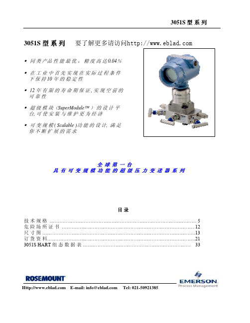
上述的参考精度包括测量的线性度、迟 滞性与重复性。
总体性能
超级型
经典型
3051S_C / T CD 量 程 2 , 3 CG 量 程 2-5
±0.125% ;在 温 度 变 化 ± 50°F(28°C) 相 对 湿 度 0-100% 、1000 psi (68.9 bar) 静 压
量 程 范 围1: ±0.1% 精度, 超 过 15:1 量 程 比, 量程上限
精 度= ±[ 0.025 + 0.005 ()]% 量程
量 程 范 围 0: ±0.10% ; 超 过 2:1量 程 比, 精 度= ±0.05%
± 0.065% 精 度; 超 过 10:1量 程 比, 量程上限
精 度 = ±[ 0.0065 ( )]% 量程
远传膜盒的解决方案。 • 标 定 量 程 从 0.1 inH2O 至 4000 psi • 过 程 隔 离 膜 片 材 质 为 316L 不 锈 钢 、 哈 氏 合 金 C 、
蒙 乃 尔 合 金 、 钽 、 镀 金 蒙 乃 尔 或 镀 金 316L 不 锈 钢 。
3051S_T 型 直 接 插 入 式(In-Line) 表压与绝压变送器
可靠性 • 超 级 模 块(SuperModule ) 的 设 计 平
台, 可 使 安 装 与 维 护 更 为 经 济 • 可 变 规 模 ( Scalable )功 能 的 设 计, 满 足
你不断扩展的需求
全全 球球 第第 一一 台台 具具 有有 可可 变变 规规 模模 功功 能能 的的 超超 级级 压压 力力 变变 送送 器器 系系 列列
氏合金C或钽金属。
3
罗斯蒙特 3051S 系列压力变送器 快速说明书

00825-0106-4801采用 HART ® 协议的罗斯蒙特 3051S 系列压力变送器采用 HART ® 协议的罗斯蒙特 3051SF 系列流量变送器© 2006罗斯蒙特股份有限公司版权所有。
保留所有权利。
商标所有人享有商标的一切财产权利。
罗斯蒙特和罗斯蒙特徽标是罗斯蒙特股份有限公司的注册商标。
第一步:安装变送器第二步:考虑外壳旋转第三步: 设置开关和跨接线第四步:接线与通电第五步:检验组态第六步:微调变送器安全仪表系统 产品认证开始结束罗斯蒙特股份有限公司8200 Market Boulevard Chanhassen,MN 美国 55317电话:(美国)(800) 999-9307电话:(国际)(952) 906-8888传真:(952) 949-7001艾默生过程管理股份有限公司Argelsrieder Feld 382234 Wessling德国电话:49 (8153) 9390传真:49 (8153) 939172艾默生过程管理亚太私营有限公司1 Pandan Crescent新加坡 128461电话:(65) 6777 8211传真:(65) 6777 0947/65 6777 0743北京远东罗斯蒙特仪表有限公司中国,北京 100013东城区和平里北街 6 号电话:(86)(10) 6428 2233传真:(86)(10) 6422 8586重要事项该安装指南为罗斯蒙特 3051S 变送器(参考手册编号00809-0106-4801)提供基本指导原则。
也为 3051SFA(参考手册文件编号 00809-0106-4809)、3051SFC(参考手册文件编号 00809-0106-4810)和 3051SFP(参考手册文件编号 00809-0106-4686)提供基本电子元件指导原则,但并不提供诊断、维护、维修或故障检修指南。
也可访问网站 ,获得该手册的电子文件。
- 1、下载文档前请自行甄别文档内容的完整性,平台不提供额外的编辑、内容补充、找答案等附加服务。
- 2、"仅部分预览"的文档,不可在线预览部分如存在完整性等问题,可反馈申请退款(可完整预览的文档不适用该条件!)。
- 3、如文档侵犯您的权益,请联系客服反馈,我们会尽快为您处理(人工客服工作时间:9:00-18:30)。
2
Classic: 0.055% span DP accuracy, 100:1 rangedown, 5-year stability
3(1)
Ultra for Flow: 0.04% reading DP accuracy, 200:1 rangedown,10-year stability, 12-year limited warranty
灵活的共面平台可与所有罗斯蒙特一次元件系列实现一体化,为所有流量测量应用提供支持。这种解决方案已经过工厂标定、 压力试验并在开箱后就可立即进行安装。只有罗斯蒙特具有能够降低工程和库存成本的规模可变的共面变送器设计。
我们测量:
• 差压 • 静压 • 过程温度
您只需输入:
• 过程介质 • 一次元件 • 管线尺寸
• Gas, natural gas, and steam measurement: Utilize full compensation (differential pressure, line pressure, and temperature measurement)
• Saturated steam: Utilize differential and line pressure, or differential pressure and temperature measurement
Measurement Type
Standard 1 2 3 4
Differential Pressure, Static Pressure, and Temperature Differential Pressure and Static Pressure Differential Pressure and Temperature Differential Pressure
• Liquids: Utilize differential pressure and temperature measurement
• Liquids at stable temperatures: Utilize differential pressure measurement
Additional Information Specifications: page 50 Certifications: page 75 Dimensional Drawings: page 78
Differential Pressure Range
Standard 0(2)(3)
1
2
3 4(2) 5(2)
-3 to 3 inH2O (-7,47 to 7,47 mbar) -25 to 25 inH2O (-62,2 to 62,2 mbar) -250 to 250 inH2O (-623 to 623 mbar) -1000 to 1000 inH2O (-2,5 to 2,5 bar) -300 to 300 psi (-20,7 to 20,7 bar)
MultiVariable Type
Standard M P
MultiVariable Measurement with Fully Compensated Mass and Energy Flow MultiVariable Measurement with Direct Process Variable Output
以下信息为流量计算所需资料:
测量介质:液体 气体 蒸汽---过热蒸汽 蒸汽---饱和蒸汽
测量介质名称:
测量介质流向:水平 垂直朝上
垂直朝下
管道尺寸(内径外径):
英寸 毫米
管道壁厚:
英寸 毫米
管道材质:碳钢 不锈钢 其他
最低操作温度:
正常操作温度:
最高操作温度:
单位:
最小操作压力:
南京办事处 南京市六合区大厂葛 关路196号 电话:025-57768588 传真:025-57768500 邮编:210048
成都办事处 成都市科华北路62号 力宝大厦 S-10-10 电话:028-62350188 传真:028-62350199 邮编:610016
深圳办事处 深圳市南山区海德三道天利 中央商务中心B座1803室 电话:0755-8659 5099 传真:0755-8659 5095 邮编:518054
Model
Transmitter Type
3051SMV Scalable MultiVariable Transmitter
Pndard
3051SMV MultiVariable SuperModule, Measurement Types 1 and 2
3(1)
客户服务热线:800-820-1996
敬请登陆: 或垂询:RMT.China@
欲了解更多艾默生过程管理公司最新罗斯蒙特测量解决方案, 请立即在 /rosemount注册。
Rosemount 3051S Series
正常操作压力:
最大操作压力:
单位:
过程最小流量:
过程正常流量:
过程最大流量:
单位:
测量介质密度:
测量介质粘度(cp):
===========================================================================
以下信息请客户根据具体工况提供
位号:
Product Data Sheet
00813-0100-4801, Rev MA
April 2010
Rosemount 3051S Scalable MultiVariable Transmitter
3051S Scalable MultiVariable Transmitter
The Rosemount 3051S Scalable MultiVariable Transmitter delivers unprecedented performance and capabilities by providing superior flow calculations including fully compensated mass or volume, energy, and totalized flow. Specify the level of compensation that best matches the application:
一体化表头: 带; 不带
变送器: 带隔爆; 带本安; 不带隔爆或本安
自定义气体为混合气体提供组分及百分比: :
49
艾默生过程 管理
上海办事处 上海市浦东金桥出口 加工区新金桥路1277号 电话:021-38954788 传真:021-58994410 邮编:201206
北京办事处 北京市朝阳区雅宝路 10号凯威大厦13层 电话:010-58211188 传真:010-58211100 邮编:100020
我们计算:
• 密度 • 粘度 • 速度 • Beta 值 • 焓值 • 气体膨胀系数 • 流出系数 • 渐进系数 • 雷诺数 • 压缩系数
您收到的是:
• 质量流量
• 热量流量
• 体积流量
• 累计流量
New
• 过程温度
• 差压
• 静压
48
罗斯蒙特 3051SF 系列
流量计选型基本信息表
======================================================================================
Ultra for Flow: 0.04% reading DP accuracy, 200:1 rangedown,10-year stability, 12-year limited warranty
5
Classic MV: 0.04% span DP accuracy, 100:1 rangedown, 5-year stability
主要特性:
• 在 14:1 流量范围内实现高达0.75%的质量流量精度 • 10 年稳定性 • 一台仪表可测量五项变量(温度,压力,差压,质量流量,热量流量) • 真正的表压测量膜头 • “实时”完全补偿质量、热量流量 • 不同测量介质实现规模可变的温压补偿 • 具有卡伦德匹配功能,提高温度测量精度70% • 共面平台为差压流量计提供支持 • HART输出
3051SMV Single Variable SuperModule, Measurement Types 3 and 4
1(2)
Ultra: 0.025% span DP accuracy, 200:1 rangedown, 10-year stability, 12-year limited warranty
47
罗斯蒙特 3051SF 系列
Qmass = N CD Y1 E d2 �D P ρ
压力和温度的变化: 5.密度的补偿 6.压缩系数
流量的变化: 4. 测量的可变因素
温度的变化: 3. E=渐进系数=1/(1-β4)1/2
流量的变化: 1. CD=流量系数; 2. Y1=气体膨胀系数
• 共面平台为差压流量计提供支持
• 10 年稳定性
通过主动测试,罗斯蒙特3051SMV已经向广大客户证明其具有在大多数要求较高的条件下能够保持出色性能的实力。绝佳的 变送器稳定性降低了标定的频率,从而降低维护和运行成本。
• 一台仪表可测量五项变量
先进的罗斯蒙特3051SMV可同时测量三种过程变量并动态计算“实时”完全补偿质量/热量流量。一台变送器就意味着降低过 程贯穿孔的数量、降低变送器备用库存、节省安装成本。
关键参数:
测量原理 质量流量精度 差压精度 压力极限值 供电 输出
关键参数