长城信息BST自助终端SP安装及维护手册
自助服务终端产品介绍及安装维护方法

自助服务终端产品介绍及安装维护方法一、自助服务终端的功能和特点1.功能:(1)银行服务:可以进行取款、存款、余额查询、账户转账和密码修改等银行业务。
(3)机票、车票等售卖:可以方便用户查询并购买机票、车票等。
(4)自助购物:可以满足用户购买日常生活用品等需求。
(6)其他服务:如查快递、打印照片、预约排号等。
2.特点:(1)自动化:自助服务终端可以通过触摸屏或键盘等操作方式,自动完成各项服务,无需人工介入。
(2)高效便捷:用户可以根据自己的需求,在任何时间、任何地点进行操作,无需排队等待。
(3)多样化服务:自助服务终端提供丰富的功能选项,满足用户不同的需求。
(4)安全可靠:自助服务终端使用高度加密的技术,保障用户的信息安全。
1.安装前准备:(1)确认用户需求:根据不同的使用场景和需求,选择适合的自助服务终端型号和配置。
(2)安装位置选择:选择一个人流量较大、空间合适且便于管理的场所进行安装。
(3)电源接口和网络接口:确保自助服务终端有稳定的电源供应和网络连接。
2.安装过程:(1)固定设备:将自助服务终端固定在安装位置上,并进行稳固的固定。
(2)连接电源和网络:将自助服务终端的电源线连接到稳定的电源插座上,并将网络线连接到稳定的网络接口。
(3)进行调试和测试:开机后,根据设备使用说明书进行调试和测试,确保各项功能正常运行。
3.维护方法:(1)设备保养:定期对设备进行清洁和维护,如清理屏幕、键盘等,保持设备的良好状态。
(2)网络安全:定期检查自助服务终端的网络安全设置,更新系统补丁,保护用户信息的安全。
三、总结自助服务终端是一种方便、高效的自动化设备,可以满足用户的多种需求。
通过合适的安装和维护方法,可以确保自助服务终端正常运行和用户信息安全。
随着科技的不断发展,自助服务终端的功能和应用场景将会不断扩展和创新,为用户带来更便捷的服务体验。
车载终端安装维护手册

霍林河露天煤业矿山GPS生产管理系统 车载终端安装维护手册目 录1 车载终端 (4)1.1 车载终端工作原理 (4)1.2 车载终端组成 (4)1.2.1 主机固定 (5)1.2.2 显示屏固定 (5)1.3 线缆制作方法 (5)1.3.1 GPS 接收器与主机之间连接电缆制作方法 (5)1.3.2 无线天线与主机之间连接电缆制作方法 (7)1.3.3 电源线缆制作方法 (10)2 分车型安装位置介绍 (12)2.1 108T自卸车 (12)2.2 TR100自卸车 (13)2.3 220T 自卸车 (15)2.4 45T 自卸车 (17)2.5 装载设备 (18)2.5.1 电铲 (18)2.5.2 挖掘机 (19)2.5.3 VOLVO 装载机 (21)2.6 工程设备 (22)2.6.1 CAT 834B 胶轮推土机 (22)2.6.2 小松 WD600胶轮推土机 (23)2.6.3 小松D375A履带推土机 (25)2.6.4 平路机 (26)2.6.5 钻机 (28)2.7 油槽车 (30)3 车载终端常见问题及解决方法 (32)3.1 没电 (32)3.2 没有GPS 信号 (32)3.3 没有无线信号 (33)4 注意事项 (34)5 维护保养 (36)1车载终端1.1车载终端工作原理车载终端安装在各个矿山设备上,通过接收无线电和GPS 信号自动处理和发送数据。
车载终端工作电压为24VDC,适合电压为18VDC 至32VDC,不大于5A 电流。
在运输自卸车、油车和所有的工程设备上从24VDC 蓄电池取电;电铲上使用专用的220VAC 转24VDC 电源适配器;车辆如果使用12VDC系统,需要使用12VDC 转24VDC 电源适配器。
主机是每个车载终端的数据处理中心,显示屏通过专用的电缆和主机相连,通过专用线缆传送图像、声音和取电。
运输自卸车和电铲设备体积大,配备两根无线天线,天线距离尽可能的远。
V150 VERIS Verabar 安装与维护指南说明书

V150 VERIS Verabar®Installation and Maintenance Manual164-EN Please read and savethese instructionsContentsGeneral Safety Information (3)Product Information (3)Section 1: Scope (3)Purpose of this Manual (3)Section 2: Receiving and InspectingReceiving and Inspecting the Verabar® (3)Section 3: Safety Precautions (3)Section 4: Installation Preparations ......................................................3-5Location (3)Orientation (4)Horizontal Piping (4)Vertical Piping (5)DP Transmitter/Local Indicator Location (5)Installation Drawings and Bill of Materials (5)Section 5: Installation Procedure .........................................................6-9Preparing the Pipe (6)Fitting Welding ..................................................................................................6-7Packing Body (7)Sensor Insertion ................................................................................................7-8Insert Instrument Vales or Manifold (9)Valves (9)Manifold (9)Pipe Pressurization (9)Section 6: Proper Installation (10)Section 7: Periodic Maintenance (10)Limited Warranty and Remedy (11)2Designs, materials, weights and performance ratings are approximate and subject to change without notice.Visit armstrong for up-to-date information.3Designs, materials, weights and performance ratings are approximate and subject to change without notice.Visit armstrong for up-to-date information.Section 1 ScopeThese instructions provide a description of procedures for installing the V150 Verabar ® model flow sensor. Procedures are given for all industrial flow measurement applications including liquid, steam and gas, for both horizontal and vertical piping configurations.Section 2 Receiving InspectionThe following tasks should be performed as part of the receiving inspection procedure:•Check items received against the packing list.•Check sensor nameplate for proper model number, serial number and tag number.•Verify the actual pipe diameter matches the ID stated on the sensor nameplate.•Check the bullet shaped sensor tube for any signs of damage. Damage to the sensor tube may result in erroneous flow readings.•Check the round cover tube for any damage, especially axial gouges or scratches. Damage to the cover tube may prevent the packing from sealing properly.Section 3 Safety PrecautionsThe following process should be conducted prior to installing the Verabar ® flow sensor:•Check the maximum operating conditions on the flow sensor nameplate. Verify that the maximum operating conditions of the application do not exceed the parameters stated on the nameplate. If any pressure, temperature, or flow limits will be exceeded, contact the factory before proceeding.•Check to ensure the pipe is depressurized and drained prior to installation.•Be cautious of pipe temperature prior to prepping the pipe for installation.•The Spring-Lock Model V150 is designed for carbon and stainless steel pipes with a schedule 10 or heavier wall thickness.The V150 should not be used with PVC, copper, aluminum, cast iron or thin-walled pipes or ducts. If there is any question as to the proper application for a model V150, consult the factory.Section 4 Installation Preparations4.1 LocationFor the most accurate flow measurement, a minimum straight run of pipe is required. Table 1 shows the minimum straight run requirements.If longer straight runs are available, position the Verabar ® such that the ratio of upstream straight run to downstream straight run is approximately 4 to 1. If straight run lengths are less than the values stated in Table 1, consult the factory for additional accuracy and location information.Straightening vanes should be positioned such that the end closest to the Verabar ® is half way between the Verabar ® and the closest upstream configuration. For elbow installations, mount the Verabar ®in the same plane as the closest upstream elbow.General Safety InformationProduct InformationInstructions and procedures listed in this manual may require special precautions to ensure the safety of the individuals performing the operations. Review the entire manual, taking note of safety messages prior to performing any operations listed in the manual.The VERIS Verabar ® averaging pitot flow sensor provides unsurpassed accuracy and reliability. With its solid, one-piece construction and bullet shape the VERIS Verabar ® makes flow measurement reliable and precise.The unique sensor shape reduces drag and flow induced vibration. The location of the low-pressure ports eliminates the potential for clogging and improves signal stability.The V150 model features mounting with threaded tube fitting components and a spring-lock feature that locks and pre-loads the sensor to the opposite pipe wall regardless of changes in pipe ID due to pressure, temperature, or mechanical force.4Designs, materials, weights and performance ratings are approximate and subject to change without notice.Visit armstrong for up-to-date information.Table 1. Straight Run Requirements4.2 OrientationVerify the proper sensor orientation by checking for an “-H” (horizontal piping) or a “-V” (vertical piping) in the model number on the Verabar ® nameplate. Deviation from the following mounting location instructions may cause inaccuracy in the flow measurement.4.2.1 Horizontal PipingFor air or gas installations, mount the Verabar ® in the upper 160° of the pipe to allow any condensate to draininto the pipe (Figure 1). For liquid or steam installations, mount the Verabar ® in the lower 160° of the pipe. Thisallows any entrained air to bleed back into the pipe for liquid applications and allows condensate to collect in theinstrument piping for steam applications.5Designs, materials, weights and performance ratings are approximate and subject to change without notice.Visit armstrong for up-to-date information.Figure 1. Verabar ® Orientation in Horizontal Pipe4.2.2 Vertical PipingThe Verabar ® may be mounted in any location around the circumference of the pipe for vertical piping applications.4.3 DP Transmitter/Local Indicator LocationWhen choosing a Verabar ® location, consider the DP transmitter/local indicator location:•The transmitter must be mounted below the Verabar ® for liquid and steam applications.•The transmitter must be mounted above the Verabar ® for air and gas applications.4.4 Installation Drawings and Bill of MaterialsAdditional information is available in the Installation Drawings and Bill of Materials VB-7061 (Contact factory for accessinformation). It contains standard and alternate transmitter locations and a complete bill of materials based on the fluid typeand sensor orientation on the pipe.6Designs, materials, weights and performance ratings are approximate and subject to change without notice.Visit armstrong for up-to-date information.Section 5 Installation Procedure5.1 Preparing the Pipe• Completely depressurize and drain pipe prior to installation of the Verabar ®.• Mark the location of the hole through which the Verabar ® will be mounted. Use a center punch to mark the hole to prevent the drill bit from walking on the pipe.• Drill the pipe with the proper sized hole per the following table (Important: Do not torch cut hole!):• IMPORTANT:Deburr the hole on the inside of the pipe.5.2 Fitting Welding• With the follower and packing rings already in place (factory assembled), loosely insert the sensor into the Spring-Lock body (see Figure 2). Thread the Spring-Lock body into the thread-o-let (hand tight), then insert the complete assembly into the pipe. This will assure proper alignment of the thread-o-let to the hole already drilled in the pipe.Figure 2. Verabar ®Model V150 AssemblySensor Cover Tube Instrument HeadIndicator RingLoad PlatePacking Rings (4)Studs (3)FollowerLock Washers (3)Packing Bolts (3)Load Nuts (3)Jam Nuts (3)Thread-o-letSpring-Lock Body7Designs, materials, weights and performance ratings are approximate and subject to change without notice.Visit armstrong for up-to-date information.Figure 3. Weld GapFigure 4. Orientation of Flow Arrow•Using the appropriate weldgap (1/16” [1.5mm] typical),tack weld the thread-o-letinto position, then removethe sensor and Spring-Lockbody. Protect threads on thethread-o-let and finish weldingthe thread-o-let to the pipe perapplicable codes (see Figure 3).5.3 Packing Body•Using appropriate pipe thread sealant, thread the Spring-Lock body into the thread-o-let.5.4 Sensor Insertion•With the follower and packing rings already in place (factory assembled), insert the sensor into the Spring-Lock body until the tip of the sensor hits the opposite side of the pipe. Note the three studs must pass through the indicator ring and the load plate.•Align the head of the sensor so that the arrow labeled “flow” on the head is in the direction of the flow in the pipe to within 3° (Figure 4). Maintain the head in this position for the remainder of the installation.•Place the three lock washers and the three load nuts on the studs and tighten. Tighten the load nuts until the load plate is 0.050” (1.3mm) from the indicator ring for –05 and –10 sensors. For –15 sensors, the load plate should be 0.063”(1.6mm) from the indicator ring (Figure 6). For –05 sensors, this can be done by tightening all the load nuts until the load plate just touches the indicator ring and then backing off all the load nuts one complete turn. For –10 and –15sensors, this can be done by tightening all the load nuts until the load plate just touches the indicator ring and thenbacking off all the load nuts 3/4 of a turn. The load springs are now properly set.Gap (1/16” [1.55mm] Typical)•Tack weld •Protect threads •Complete weld Vertical Pipe OrientationsHorizontal Pipe OrientationsDirection of Flowof FlowDirection of Flow8Designs, materials, weights and performance ratings are approximate and subject to change without notice.Visit armstrong for up-to-date information.Figure 5. Spring-Lock Cut Away•Thread on the three jam nuts and tighten until they are resting hand-tight against the lock nuts. Place a backup wrench on the load nut to prevent it from rotating. While not allowing the load nut to rotate, tighten the jam nuts 1/8 turn beyond hand tight.•Using a torque wrench, tighten the three packing bolts to the appropriate torque value listed in the table below.•Note: The weld on the weld ring (Figure 6) should not contact the top surface of the follower. If the weld on the weld ring comes into contact with the follower, the sensor will not be properly bottomed in the pipe. If this occurs, consult thefactory before proceeding.Jam NutLoad NutLock WasherPacking Bolt Packing RingFollowerLoad SpringsIndicator RingLoad PlateStudLocation of Pressure Stomp Spring-Lock Body9Designs, materials, weights and performance ratings are approximate and subject to change without notice.Visit armstrong for up-to-date information.5.5 Insert Instrument Vales or Manifold5.5.1 Valves•If the Verabar ® does not have a valve head, install instrument valves using proper thread sealant. Be sureinstrument shut-off valves are installed and shut prior to re-pressurizing the pipe.5.5.2 Manifold•If the Verabar ® has a direct or integral manifold, be sure the high and low pressure block valves are shut offprior to re-pressurizing the pipe.5.6 Pipe Pressurization•Pressurize the pipe and check for leaks. If leaks are present, retighten the packing bolts until leaking iseliminated. Verify that the distance between the load plate and the indicator ring is approximately 0.050”(1.3mm) for -05, and -10 sensors and 0.063” (1.6mm) for -15 sensors; make adjustments as required.Figure 6. Proper Spring CompressionFollowerLoad PlateIndicator RingTop Surface ofFollowerWeld RingGap10Designs, materials, weights and performance ratings are approximate and subject to change without notice.Visit armstrong for up-to-date information.Section 6 Proper Installation6.1 The Verabar ® is now properly installed (Figure 7).Section 7 Periodic MaintenanceThe assembly should be periodically checked. Verify that no leaks are present. Tighten the packing bolts if necessary. Inspect sensor for wear or damage.Note: Different threads require different maintenance requirements.Figure 7. Installed V15011Designs, materials, weights and performance ratings are approximate and subject to change without notice.Visit armstrong for up-to-date information.VERIS, Inc. (“VERIS”) warrants to the original user of those products supplied by it and used in the service and in the manner for which they are intended shall be free from defects in material and workmanship for a period of five (5) years from the date of installation, but not longer than 63 months from the date of shipment from the VERIS factory, unless a Special Warranty Period applies, as noted below. This warranty does not extend to any product that has been subject to misuse, neglect or alteration after shipment from the VERIS factory. Except as may be expressly provided in a written agreement between VERIS and the user, which is signed by both parties, VERIS DOES NOT MAKE ANY OTHER REPRESENTATIONS OR WARRANTIES, EXPRESS OR IMPLIED, INCLUDING, BUT NOT LIMITED TO, ANY IMPLIED WARRANTY OF MERCHANTABILITY OR ANY IMPLIED WARRANTY OF FITNESS FOR A PARTICULAR PURPOSE. The sole and exclusive remedy with respect to the above limited warranty or with respect to any other claim relating to the products or to defects or any condition or use of the products supplied by VERIS, however caused, and whether such claim is based upon warranty, contract, negligence, strict liability, or any other basis or theory, is limited to VERIS’ repair or replacement of the part or product, or, at VERIS’ option, to repayment of the purchase price. In addition to replacing any part of parts found to VERIS’ satisfaction to be defective, VERIS will pay the cost of shipment of both the defective part to the VERIS plant and the replacement part to the original user. As a condition of enforcing any rights or remedies relating to VERIS products, notice of any warranty or other claim relating to the products must be given in writing to VERIS: (i) within 30 days of last day of the applicable warranty period, or (ii) within 30 days of the date of the manifestation of the condition or occurrence giving rise to the claim, whichever is earlier. IN NO EVENT SHALL VERIS BE LIABLE FOR SPECIAL, DIRECT, INDIRECT, INCIDENTAL OR CONSEQUENTIAL DAMAGES, INCLUDING, BUT NOT LIMITED TO, LOSS OF USE OR PROFITS OR INTERRUPTION OF BUSINESS. The Limited Warranty and Remedy terms herein apply notwithstanding any contrary terms in any purchase order or form submitted or issued by any user, purchaser, or third party and all such contrary terms shall be deemed rejected by VERIS.Special Warranty Periods are as follows:Electronic components, including without limitation, differential pressure transmitters, multivariable transmitters, flow computers, rate or totalizer displays: one (1) year from the date of installation, but not longer than 15 months from the date of shipment from the VERIS factory.VERIS, Inc.Limited Warranty and RemedyArmstrong VERIS Flow Measurement Group5820 Glacier Way , Frederick, CO 80516 - USA Phone: 303-652-8550 Fax: 303-652-8552armstrong 164-ENPrinted in U.S.A. - 1/29/16© 2016 Armstrong International, Inc.Designs, materials, weights and performance ratings are approximate and subject to change without notice.Visit armstrong for up-to-date information.V150 VERIS Verabar ®Installation and Maintenance Manual。
用 户 手 册 - 长城信息产业股份有限公司

为了提高自助终端的部件及整机的系统性能和可靠性,我们会对硬件或软件做 一些改动,这样可能造成软硬件配置与用户手册的不一致,请您谅解。
限于编者水平,用户手册恐仍有疏漏不妥之处,如果您在使用中发现手册中有 任何错误或者您有什么问题,请与我们联系(0731)84932700。
170
BST508 壁挂式 731* 468* 370 60
17"
105
BST508A 壁挂式 731* 468* 370 60 15"/17" 105
BST509 壁挂式 627* 410* 290 35 10.4"
80
BST601
立 式 1560* 520* 530 120
15"
65
BST601C 立 式 1487* 580* 629 55
GWI
长城信息
BST 系列多媒体自助终端
用பைடு நூலகம்手册
版本号:V3.0 湖南长城信息金融设备有限责任公司
GWI BST 系列自助终端通用用户手册
修改记录
版本号
V1.0 V2.0 V2.1 V3.0
修改时间
修改说明
2009 2011.09 2011.12
初始版本
新增型号:BST601C/S、BST602A、BST610、BST220、 BST220A、BST306A、BST306N、BST508A、BST509、 BST312C;额定功率改为平均功耗;增加安全警告。
5
GWI BST 系列自助终端通用用户手册
目录
警 告............................................................................................................................................ 3 安全使用注意事项.......................................................................................................................... 4 前 言.......................................................................................................................................... 5 第一章 自助终端硬件使用环境及要求 ........................................................................................ 7 第二章 BST 系列产品简介 ........................................................................................................... 8 第三章 使用与维护...................................................................................................................... 17 第四章 常见故障及处理方法...................................................................................................... 28 第五章 自助终端硬件测试程序.................................................................................................. 30 湖南长城信息金融设备有限责任公司三包服务承诺 ................................................................ 31 三包凭证........................................................................................................................................ 32 客户信息调查反馈表.................................................................................................................... 33 有毒有害物质或元素名称及含量标识 ........................................................................................ 34
BST 自动化系统 BST-et 1500-WWM 使用手册 中文版

BST 自动化系统BST-et 1500-WWM使用手册BST Servo-Technik GmbHHeidsieker Heide 5333739 Bielefeld德国电话: 05206/999-0传真: 05206/999-999E-mail: info@1 软件简介本软件"BST-et 1500-WWM"用于纪录单轨或多轨水平测量,并将测量结果通过BST-et 1500传送至个人计算机.该软件的多模式操作必须具备BST”软件狗”才能实现.2 "演示"和"分析"模式可以免费使用.3 系统配置最低要求-操作系统:Windows 9x或Windows NT4.0以上-单个测量位置主频要求为奔腾®100,多个测量位置则要求有更高的主频.-32M内存4 软件运行的前提1)必须在用户手册的指导下使用et 1500.2)在1-2个端口上有et 1500的跨接 JX8.3)连接et 1500 (socket X4) 和计算机(串行接口)产品,数据线参数见36.629.00.4.30的连接手册.4)软件狗必须插在计算机并行接口上.5 软件的安装:·双击" Setup.exe"文件,启动安装程序.随后出现一个窗口,要求关闭所有其他运行的程序.关闭所有其他运行的程序,然后点击O.K.·点击这个按钮,开始安装.·如果你不想在给出的路径安装该程序,点击这个按钮.·结束安装,点击这个按钮.·安装过程中可能会出现如下提示:“访问拒绝”“服务已经存在”等等,这时可以选择”忽略”,或”是”以确认.这些提示的出现是因为现有版本的软件已经存在于目标计算机上,或正在执行.所以尽管出现这些提示,BST-et 1500-WWM程序仍将运行.注意:Windows操作系统必须用”小一”号字体.方法:用鼠标右键点击桌面,点击属性,再点击”设置”选项卡,双击窗口位置,选择”小一号字体”.6 点击”OK"确认设置,开始运行程序"BST-et 1500-WWM"6.1测量位置的设置双击文件BST-et 1500-WWM.exe,开始运行程序.这时出现开始窗口.打开顶部下拉菜单中的”工具”,点击”选项”.系统会弹出来一个对话框,用户可以进行设置.填入一个数字,确定需要监视的串行接口.这里表示监视标准通信端口1(COM-Port 1).这个选择框表示计算机的速度,必须与软件的传输速度一致.标准交换速度为9600波特.·选项”通过动态数据交换(DDE)与et 1500连接”,建立连接.·不要点击的选项:软件直接连接到通信端口.·选择选项:用该软件单独启动一个程序,在将这一程序连接到通讯端口,将该软件的数据交由DDE处理.何时使用何种连接方式:只有测量位置需要纪录时,et 1500才可以直接接到通信端口,因此不要点击这个选项,以节约动态数据交换(DDE)连结和数据传输的成本.如果需要纪录某几个数值,必须决定是将来自et 1500的数据分配到几个通信端口,还是只用一个通信端口,将数据通过DDE送至相应的纪录软件.例1 :将数据分配给数个通信端口:在这种情况下,计算机必须有数个串行通信端口,来自et 1500的数据线必须并行按比例分配.对速度较慢的处理器,我们推荐这种连接方式.例二: 例二:几个纪录器只使用一个通信端口这种连接需要额外的计算机资源,所以可以与处理速度较快的计算机(如300HZ以上)联网使用。
智能终端操作手册

智能终端操作手册咨询热线:96599●欢迎您使用智能终端手册目录一、简介 (1)二、注意事项 (1)三、安装指南 (2)3.1 设备接口说明: (2)3.2 设备连接示意图 (3)3.3 智能卡使用说明 (3)3.4 遥控器使用说明 (4)3.4.1.按键说明 (4)3.4.2 学习型遥控器的学习方法: (6)四、产品功能介绍 (7)4.1电视直播 (8)4.2互动电视 (13)4.3 TV生活 (13)4.4 Net影院 (16)4.5 视频通讯 (19)4.6 应用天地 (21)4.7 我的电视 (22)五、故障现象及排除 (26)六、安广分公司的营业厅 (28)七、清单 (29)一、简介安广智能终端致力于打造智能数字生活。
提供丰富的内容,舒适的用户体验。
高清直播:提供高清直播服务,在客厅享受高清影院。
TV生活:在这里可以体验到把商店搬回家的感觉,足不出户的逛各大商店、4S店,以及提供便户的查询服务。
Net影院:海量的电影,电视剧、动漫,综艺;聚合互联网丰富的内容,为您提供高清家庭影院般的享受。
可视电话:与亲朋好友面对面的交流,及时分享家的感觉。
应用天地:各种应用与游戏应有尽有,打造数字娱乐的生活。
内置WIFI:为家庭提供无线网络服务。
互动电视:想看就看,想点就点,海量高清片库。
二、注意事项●插入或拔出电源线时,勿用湿手。
●勿将重物放于电源线上或放置于本机上。
智能卡保护为防止造成智能卡损坏以及可能出现解密不正常的情况,请注意下列事项。
●开启智能终端电源前,请先插好智能卡。
●智能终端在工作状态下,请勿插拔智能卡。
安全放置●勿将本机放置于有强烈机械振动、多尘和潮湿的地方●勿将本机靠近热源或者使用保温材料包裹;●机体四周应有足够的空隙,以便通风散热。
其它事项●若长时间不用或机体破裂时,请拔掉电源插座。
●清洁之前请从插座上拔掉电源插头,用干布清洁外表面,勿将液体、喷雾剂或其它物品流入机内,否则可能发生严重损害。
长城证券金证Linux热自助安装说明

长城证券金证Linux热自助安装说明一、营业部热键部署示意图二、硬件需求1.硬件最低配置要求:运行金证Linux热自助最低的硬件配置要求为CPU X86266MHZ以上、内存32MB以上、显卡至少支持VESA SVGA图形模式、网卡。
三、软件需求1.软件最低配置要求:无盘站启动金证Linux热自助时需要使用到一些必要的命令,例如cut , tr , insmod , ifconfig ,首先保证系统中已存在这些命令(金证Linux热自助安装包中自带了cut和tr命令,通达信特殊版本自带了insmod.static,本手册将统一使用钱龙做为Linux系统样本)。
所用的Linux系统必须开启支持内核动态模块加载。
2.MID中间件要求:为使LINUX热自助升级包升级完后能够正常运行,MID中间件需要求升级至最新版,如果客户没有进行升级,可以到金证官网下载,选择证券-外围系统,然后选择PATCH3.3.4(R)_WWXT33_2014C_完整版、PATCH3.3.4.2_UPD005(R)_WWXT33_2014H_升级包(20141024沪港通)、PATCH3.3.4.2_UPD007(R)_WWXT33_2014J_升级包(20141111沪港通)这三个包进行下载,先将后面两个升级包的程序替换完整版的里面的文件,再进行安装。
四、安装准备1.备份如果原先已安装过金证Linux热自助,那么升级前请先备份旧的热自助。
备份可以使用以下命令进行备份:cp –R /opt/qianlong/client/kd32/wwxt33/tsrc33/opt/qianlong/client/kd32/wwxt33/tsrc33_bak2.复制必要的安装文件将热自助安装包中的install.sh, install-en.sh, uninstall.sh,tsrcdoit.sh, rzrqmacaddr, tsrc33.tar.gz拷贝至Linux任意目录下(保证以上文件在同一个目录)。
OA移动终端安装维护手册

移动授权............................................................................................................... 7 3.3.1 3.3.2 3.3.3 授权人员查看.............................................................................................. 7 授权人员分配.............................................................................................. 7 其它.............................................................................................................. 9
3.3.2 授权人员分配
双击“被授权用户”文本框,弹出选人窗口,如图:
北京致远协创软件有限公司
7 / 12
中国协同软件市场连续六年占有率第一
图-选择授权人员 选人后,点“提交”按钮,返回单位授权主页面。已使用注册数和被授权用户已发 生变化,如图:
北京致远协创软件有限公司
注:A6-m v3.0 sp1 版本,Https 支持已内置在标准产品中,不需要额外插件,仅 需部署时开启即可。
4.2 VPN 支持
由于 M1 的运行环境是移动设备,所以对于 VPN 的支持取决于移动终端的系统环境以及 VPN 厂家的客户端支持,以下为您列举截止 M1 发版时已知 VPN 支持情况: 1、PPTP(点对点隧道协议) VPN PPTP 协议属于数据链路层协议,具有较强的通用性,目前 Ipad、Iphone、Android 对 其均有良好的支持,所以市面上所有 PPTP 类型 VPN 产品我们均可兼容。
终端产品维护手册(STAR-56II)
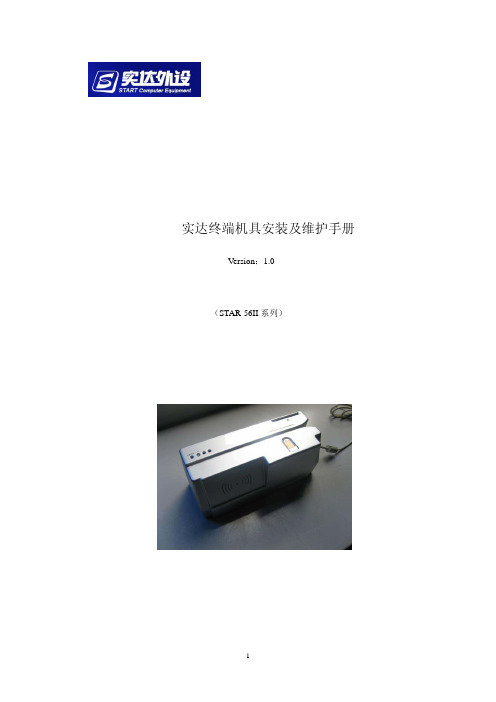
实达终端机具安装及维护手册Version:1.0(STAR-56II系列)目录第一章 产品功能介绍---------------------------------------(3) 第二章 产品硬件介绍---------------------------------------(6) 第三章 产品自检方式---------------------------------------(7) 第四章 常见故障及解决方法---------------------------------(11)第一章 产品功能介绍一、产品简介该产品基于全新的设计理念,外观精巧,结构合理,具备超强的集成能力。
产品可同时磁条读写器、接触/非接触式IC卡、二代身份证阅读器、指纹识别仪等多种模块。
产品以模块化的设计理念,采用了高品质、低功耗、长寿命的功能模块,从而实现了产品超强的稳定性、兼容性以及便捷的维护性。
z主要功能A.银行卡磁卡读写功能B.银行IC卡应用功能C.二代身份证信息读取功能D.指纹识别功能z产品特点A.磁卡机部分1、磁头采用高抗磁铁硅铝磁头,保证了银行卡及存折在读写作业中的稳定可靠。
高抗磁铁硅铝磁头具有以下特点:1)硬度高:不易磨损,寿命长。
2)导磁率高:保证写磁稳定可靠。
3)杂质、气孔少:长时间使用不易生锈2、编码器。
光电管采用著名传感器品牌“霍尼韦尔”,使编码器的使用寿命大幅提升。
3、读磁头对面的压力机构。
采用磁带压带滚轮设计,大大减小了对卡片的划伤问题,增强了刷卡的稳定性。
4、磁卡导槽防磨设计,导槽底部采用金属件,避免长期刷卡、刷折对导槽的造成磨损B.指纹模块部分1、指纹模块核心部件是指纹传感器,采用的是国际主流瑞典FPC传感器。
该传感器有以下几个优点:1)表面采用超强防刮保护表面涂层,保护层是同类厚度的10-25倍,耐磨100万次;2) 抗静电ESD>±15KV ,达到4 IEC 61000-4-2 标准;3) 高品质的传感器确保了FPC 反射式探测信号增强,不仅提高了指纹识别性能,而且还增强了保护层的厚度;4) 耐受温度 -90~100℃,极速变化 -70至85 ℃。
长城终端手册

手册声明1. 本手册及其描述的硬件和软件内容属于湖南计算机股份有限公司知识产权所有,未经本公司同意,任何人或机构不得非法复制、改动或存贮在任何包括磁、机械、光的材料之中,或将手册的任何部分翻译成任何语言。
2. 本手册中提到的商标都是属于它们各自公司或厂商所有。
3. 湖南计算机股份有限公司享有本手册的最终解释权和修改权。
如有修改,恕不另行通知。
目录第一章概述 (1)第二章终端的安装与联接 (3)第三章终端功能 (11)3.1键盘功能 (11)3.2S E T U P设置 (12)3.3汉字输入 (13)3.4辅助功能 (15)3.5双会话(主机)功能 (16)3.6多屏功能 (16)3.7窗口管理 (17)3.8画面存储 (17)3.9图形功能 (17)3.10打印功能 (21)3.11外设管理 (21)3.12I C卡 (24)第四章仿真方式 (27)4.1V T400/V T100仿真 (27)4.2X E N I X仿真 (27)4.3C T100仿真控制命令 (27)4.4V T52仿真 (30)4.5C T24仿真 (30)第五章辅口跳线汇总 (35)5.1G W220H/G W600I跳线 (35)5.2G W510跳线说明 (35)5.3G W680跳线说明 (36)5.4G W680S跳线说明 (36)5.5G W710跳线说明 (37)5.6G W810跳线说明 (37)5.7G W810A跳线说明 (39)5.8G W810C跳线说明 (39)5.9G W860跳线说明 (40)5.10G W860A跳线说明 (40)5.11G W910跳线说明 (40)5.12G W920跳线说明 (40)5.13G W950跳线说明 (40)第六章设驱动示例 (41)第七章常见问题处理 (49)附录一字豪码汉字输入法(G W810以上) (52)附录二命令集 (66)第一章概述前言您好! 欢迎您使用长城中西文字符图形显示终端或液晶显示终端(以下简称长城终端)!本手册主要针对于程序开发与外设连接的较全面介绍,一些基本介绍及基本概念请到上查找,如果您在使用本终端时发现什么问题, 请拨电话:(技术支持), (维修),Email: , 对您的支持,我们表示万分的感谢!长城终端的主要技术指标•屏幕显示显示器:9”、14”纸白色CRT或”LCD(GW910、GW950)显示格式:西文:8×18点阵或12×24点阵中文:16×16点阵(GW220H、GW510、GW680、GW680S、GW910)24×24点阵(GW710、GW810、GW810A、GW810C、GW860、GW920)支持24或25行,80列或132列的显示。
BST3.0安装维护手册

BST3.0应用软件开发平台安装维护手册云南南天电子信息产业股份有限公司目录第一章BST系统安装 (3)第二章系统操作 (5)第三章BST应用系统的交易定制 (7)第一章 BST系统安装BST3.0开发平台是建立在WINDOWS98/2000/NT操作系统上的,安装介质是光碟(1张),安装所用的计算机预先需安装WINDOWS98/2000/NT,它对硬件配置的要求如下:●CPU是奔腾MMX166以上。
●硬盘2G以上。
●内存32M以上。
●声卡。
一.系统安装步骤1、开机,放入安装光牒,运行“BST2.1开发平台”目录下的setup.exe。
2、出现“Welcome”画面时按“Next”继续。
3、出现“User Information”对话框,按提示输入后,按“Next”继续。
4、出现“Chose Destination Location”对话框,按“Browse”按钮选择目标路径,(例如选择c:\nantian目录)选择完成后按“Next”继续。
5、出现“Select Program Folder”对话框,选择“启动”,按“Next”继续。
6、出现“Start Copy File”对话框,对话框中描述了安装的情况,按“Next”开始拷贝文件。
7、拷贝文件完成后,出现“Setup Complete”对话框,按“Finish”结束安装。
二.注册表引入上述安装步骤正确完成后,在“C:\nantian”目录下生成一系列相关文件和子目录,它们共同组成了一个BST应用系统的范例(Demo),这个范例可用于演示、硬件及老化实验的测试。
运行该范例程序前,首先应先将与BST应用系统有关的注册表加入注册表系统,具体操作如下:1、运行c:\windows\regedit.exe。
2、选“注册表”菜单条。
3、选“引入注册表”。
4、将“c:\nantian\register\register.reg”打开。
5、系统提示注册表成功引入。
SCXI-1326高压终端板安装指南说明书
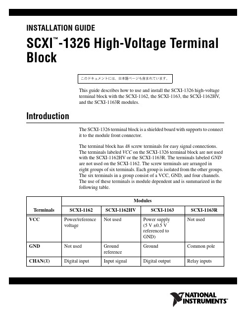
INSTALLATION GUIDESCXI -1326 High-Voltage Terminal Block This guide describes how to use and install the SCXI-1326 high-voltageterminal block with the SCXI-1162, the SCXI-1163, the SCXI-1162HV , and the SCXI-1163R modules.IntroductionThe SCXI-1326 terminal block is a shielded board with supports to connectit to the module front connector.The terminal block has 48 screw terminals for easy signal connections.The terminals labeled VCC on the SCXI-1326 terminal block are not usedwith the SCXI-1162HV or the SCXI-1163R. The terminals labeled GNDare not used on the SCXI-1162. The screw terminals are arranged ineight groups of six terminals. Each group is isolated from the other groups.The six terminals in a group consist of a VCC, GND, and four channels.The use of these terminals is module dependent and is summarized in thefollowing table.TerminalsModulesSCXI-1162SCXI-1162HV SCXI-1163SCXI-1163R VCC Power/referencevoltage Not used Power supply (5 V ±0.5 Vreferenced toGND)Not used GND Not used Ground reference GroundCommon pole CHAN(X )Digital input Input signal Digital output Relay inputs™̭͈Ρ΅νιϋΠ͉ͅȂ βȜΐ͜ ̞̳ͦ̀͘͘ȃSCXI-1326 Installation Guide What You Need to Get StartedTo set up and use your SCXI-1326 terminal block kit, you need thefollowing components:❑SCXI-1326 High-Voltage Terminal Block Installation Guide❑SCXI-1326 high-voltage terminal block❑SCXI chassis❑SCXI-1162, SCXI-1163, SCXI-1162HV , or SCXI-1163R module❑Number 1 and 2 Phillips-head screwdrivers❑1/10 in. and 1/4 in. flathead screwdrivers❑Needle-nose pliers❑Wire cutter❑Wire insulation stripperConventionsThe following conventions are used in this guide:This icon denotes a note, which alerts you to important information.This icon denotes a caution, which advises you of precautions to take toavoid injury, data loss, or a system crash.italic Italic text denotes variables, emphasis, a cross-reference, or an introductionto a key concept. Italic text also denotes text that is a placeholder for a wordor value that you must supply.monospaceText in this font denotes text or characters that you should enter from thekeyboard, sections of code, programming examples, and syntax examples.This font is also used for the proper names of disk drives, paths, directories,programs, subprograms, subroutines, device names, functions, operations,variables, filenames and extensions, and code excerpts.Safety Informationflammable gases or fumes.Keep away from live circuits. Do not remove equipment covers or shields unless you aretrained to do so. If signal wires are connected to the device, hazardous voltages may existeven when the equipment is turned off. To avoid a shock hazard, do not perform proceduresinvolving cover or shield removal unless you are qualified to do so and disconnect all fieldpower prior to removing covers or shields.Equipment described in this document must be used in an Installation Category IIenvironment per IEC 664. This category requires local level supply mains-connectedinstallation.Do not operate damaged equipment. The safety protection features built into this devicecan become impaired if the device becomes damaged in any way. If the device is damaged,turn the device off and do not use until service-trained personnel can check its safety. Ifnecessary, return the device to National Instruments for service and repair to ensure that itssafety is not compromised.Do not operate this equipment in a manner that contradicts the information specified in thisdocument. Misuse of this equipment could result in a shock hazard.Terminals are for use only with equipment that has no accessible live parts.Do not substitute parts or modify equipment. Because of the danger of introducingadditional hazards, do not install unauthorized parts or modify the device. Return thedevice to National Instruments for service and repair to ensure that its safety features arenot compromised.When using the device with high common-mode voltages, you must insulate your signalwires for the highest input voltage. National Instruments is not liable for any damages orinjuries resulting from inadequate signal wire insulation. Use only 26-14AWG wire witha voltage rating of 300V and 60 °C for signals that may come in contact with 300V.When connecting or disconnecting signal lines to the SCXI terminal block screw terminals,make sure the lines are powered off. Potential differences between the lines and the SCXIground create a shock hazard while you connect the lines.Connections, including power signals to ground and vice versa, that exceed any of themaximum signal ratings on the SCXI device can create a shock or fire hazard or candamage any or all of the boards connected to the SCXI chassis, the host computer, and theSCXI device. National Instruments is not liable for any damages or injuries resulting fromincorrect signal connections.If high voltages (≥30 V rms and 42.4 V peak or 60 VDC) are present, you must connect a safetyearth ground wire to the terminal block safety ground solder lug, shown in Figure1. Thiscomplies with safety agency requirements and protects against electric shock when the© National Instruments Corporation3SCXI-1326 Installation GuideSCXI-1326 Installation Guide terminal block is not connected to the chassis. To connect the safety earth ground to the safety ground solder lug, run an earth ground wire in the cable from the signal source to the terminal block. National Instruments is not liable for any damages or injuries resulting from inadequate safety earth ground connections.Do not loosen or re-orient the safety ground solder lug hardware when connecting thesafety ground wire; to do so reduces the safety isolation between the high voltage and safety ground.Signal ConnectionNote Refer to the Safety Information section before removing equipment covers orconnecting or disconnecting any signal wires.When connecting your signals to the SCXI-1326, follow the labeling on theSCXI-1326 for the appropriate module, as indicated in Figure 2.To connect the signal to the terminal block, perform the following steps,referring to Figures 1 and 2 as necessary:1.Unscrew the top cover screws and remove the cover.2.Loosen the strain-relief screws and remove the strain-relief bar.3.Run the signal wires through the strain-relief opening. You can add insulation or padding if necessary.4.Prepare your signal wire by stripping the insulation no more than 7mm.5.Connect the wires to the screw terminals by inserting the stripped endof the wire fully into the terminal. No bare wire should extend past thescrew terminal. Exposed wire increases the risk of shorting andcausing a failure.6.Tighten the screws to a torque of 5–7 in.-lb.7.Connect safety earth ground to the safety-ground solder lug. Refer tothe Safety Information section for connection information.8.Reinstall the strain-relief bar and tighten the strain-relief screws.9.Reinstall the top cover and tighten the top cover screws.10.Connect the terminal block to the module front connector as explainedin the Installationsection.© National Instruments Corporation 5SCXI-1326 Installation GuideFigure 1 shows the SCXI-1326 terminal block parts locator diagram.Figure 1. SCXI-1326 Parts Locator Diagram 1Strain-Relief Bar 2Strain-Relief Screws 3Safety-Ground Solder Lug 4Mating Connector 5Thumbscrew 6Top Cover Screws 7Top CoverFigure2 shows the SCXI-1326 signal connections.1Screw Terminals2Product Name, Assembly Number, Revision Letter, and Serial Number3Warning LabelFigure 2. SCXI-1326 Signal Connections InstallationTo connect the terminal block to the SCXI module front connector, performthe following steps:1.Connect the module front connector to its mating connector on theterminal block.2.Tighten the top and bottom thumbscrews on the back of the terminalblock to hold it securely in place.Cleaning the Terminal BlockClean the terminal block by brushing off light dust with a soft, nonmetallicbrush. Remove other contaminants with deionized water and a stiffnonmetallic brush. The unit must be completely dry and free fromcontaminants before returning to service.SCXI-1326 Installation SpecificationsCommon-mode isolationBank to bank...................................300 V rmsBank to earth...................................300 V rmsEnvironmentOperating temperature............................0 to 50 °CStorage temperature...............................–20 to 70 °CRelative humidity...................................5% to 90% noncondensingSafetyDesigned in accordance with IEC 61010-1, UL 3111-1, and CAN/CSAC22.2 No. 1010.1 for electrical measuring and test equipment.Approved at altitudes up to 2000 meters.Installation Category IIPollution Degree 2Technical Support ResourcesNI Web SupportTo provide you with immediate answers and solutions 24hours a day,365days a year, National Instruments maintains extensive online technicalsupport resources. They are available to you at no cost, are updated daily,and can be found in the Technical Support section of our Web site at/supportWorldwide SupportNational Instruments has offices located around the globe. Many branchoffices maintain a Web site to provide information on local services. Youcan access these Web sites from /worldwideFor telephone support in the United States, dial 5127958248. Fortelephone support outside the United States, contact your local branchoffice:Australia1800300800, Austria43662457990-0,Belgium32(0)27570020, Brazil551132623599,Canada8004333488, China862150509800,Czech Republic420224235774, Denmark4545762600,© National Instruments Corporation7SCXI-1326 Installation GuideFinland358(0)972572511, France0157662424,Germany49897413130, India918041190000, Israel97236393737,Italy390241309277, Japan0120-527196, Korea820234513400,Lebanon961(0)1332828, Malaysia1800887710,Mexico018000100793, Netherlands31(0)348433466,New Zealand0800553322, Norway47(0)66907660,Poland48223390150, Portugal351210311210, Russia74957836851,Singapore180********, Slovenia38634254200,South Africa270118058197, Spain34916400085,Sweden46(0)858789500, Switzerland41562005151,Taiwan8860223772222, Thailand6622786777,Turkey902122793031, United Kingdom44(0)1635523545National Instruments, NI, , and LabVIEW are trademarks of National Instruments Corporation. Refer to the Terms of Use section on/legal for more information about National Instruments trademarks. Other product and company names mentioned herein are trademarks or trade names of their respective companies. For patents covering National Instruments products, refer to the appropriate location: Help»Patents in your software, the patents.txt file on your CD, or /patents.© 1994–2008 National Instruments Corporation. All rights reserved.371928C Mar08。
自助设备操作手册
自助设备操作手册本操作手册为自助设备的使用指南,旨在帮助用户正确、便捷地操作自助设备。
1. 操作准备在使用自助设备之前,请确保以下事项已经准备就绪:- 确认设备已经连接到电源,并且处于正常工作状态。
- 验证您拥有使用该设备的权限或许可。
- 准备好您需要进行操作的个人信息或文件。
2. 登录与注销2.1 登录1. 启动自助设备并等待系统启动完成。
2. 在屏幕上输入您的用户名和密码。
3. 点击登录按钮。
2.2 注销1. 在当前页面中,点击注销按钮。
2. 确认注销操作。
3. 功能与操作自助设备提供了一系列功能,您可以根据需求进行选择并进行操作。
以下是常见功能的操作步骤。
3.1 打印文件1. 在系统桌面或主界面上找到打印功能图标。
2. 点击打印图标,进入打印页面。
3. 选择您需要打印的文件,并进行相关设置(如打印份数、纸张大小等)。
4. 确认设置后,点击打印按钮,等待打印完成。
3.2 扫描文件1. 打开扫描功能,并将需要扫描的文件放置在扫描设备上。
2. 选择扫描设置,如扫描分辨率、文件格式等。
3. 点击开始扫描按钮,等待扫描完成。
4. 在扫描完成后,您可以选择保存扫描文件到指定位置或进行其他相关操作。
3.3 查询信息1. 打开查询功能,并选择您希望查询的项目。
2. 输入查询条件,如关键词、日期等。
3. 点击查询按钮,等待查询结果显示。
4. 常见问题与解决方法4.1 设备无法启动如果自助设备无法启动,请尝试以下解决方法:- 检查电源连接是否正常。
- 确保设备处于工作温度范围内。
- 重新启动设备或联系技术支持。
4.2 打印机出现故障如果打印机出现故障无法正常工作,请尝试以下解决方法:- 确认打印纸张已装好并无卡纸现象。
- 关闭并重新启动打印机。
- 联系技术支持或设备维护人员。
5. 安全注意事项在使用自助设备时,请遵守以下安全注意事项:- 不要将您的个人信息泄露给他人。
- 不要进行未授权的操作或破解设备限制。
- 如遇到设备异常或问题,及时联系相关人员解决。
BSC操作维护手册

BSC操作维护手册(2007版)目录前言 (2)第一章常用基本指令汇总 (5)第一节外部告警 (5)第二节有关传输的指令 (6)第三节有关MO类指令 (7)第四节有关小区类指令 (9)第二章基站设备监控维护 (11)第一节基站设备故障监控与排除 (11)第二节日常维护工作 (14)第三节直放站设备监控维护 (19)第三章载波数据制作 (20)第四章基站数据制作 (22)第一节小区参数设置规范 (22)第二节小区数据定义 (34)第三节 RBS200基站数据制作(参考R.7数据制作) (43)第四节 RBS2000基站数据制作(参考R7.1数据制作) (56)第五章故障难点与重点(例子诠析) (62)第一节如何定义一个新的TG号 (62)第二节如何退传输 (66)第三节如何加传输 (69)第五节如何改压缩方式 (75)第六节如何改跳频方式 (76)第七节RBS2302换RBS2308(含定义EDGE载波) (77)第八节RBS2308换RBS2302(含退EDGE载波) (78)第六章常见故障的处理 (79)第一节时隙不同步或配置不上的原因及处理方法 (79)第二节常见CF类告警 (82)第三节常见TRX类告警 (84)第四节常见TX类告警 (86)第五节常见RX类告警 (88)前言在进入章节之前,我们先简单了解一下BSC(基站控制器)里面所涉及到的一些MO及其状态。
一、MO的结构MO:(MANAGED OBJECT)管理对象;BSC:(BASE STATION CONTROLLER)基站控制器,属GSM网络单元,用于控制一个或若干个BTS;BTS:(BASE TRANSCEIVER STATION)GSM网络单元,是指工作于一个小区的一组无线载频的所有设备的总和;CELL:蜂窝小区,指一个基站的一个天线系统的无线覆盖范围;TG:(TRANSCEIVER GROUP)收发信机组,即被定义为和一个天线系统相连的所有收发信机的总和;CF:支持BTS的O&M;CON:用于对信令的集中与分解;IS:用于对BSC和TRU的PCM时隙进行交换、标准是16KBIT/S;TF:(TIMING FUNCTION)同TM相关联的逻辑单元,提供TRU的时钟信号,用于产生TDMA 帧和无线频率参考信号;DP:用于对传输质量和故障进行监测;TRX:(TRANSCEIVER)收发信机,GSM网络实体,用于无线发射/接收以及信号处理,它与8个BPC上的话务相关联,即与属于一个TDMA帧的所有BPC相关联;TRXC:(TRANSCEIVER CONTRALLER)RBS200的硬件单元,它通过所属的RRX和SPP控制8个BPC,TRXC作为TGC时,它主控该TG的公共资源,即主控TRX和TM;RTX:(RADIO TRANSMITTER)无线发射机,RBS200的硬件单元,用于射频发射的调制;RRX:(RADIO RECEIVER)无线接收机,RBS200的硬件单元,用于接收和处理射频信号;TX:(TRANSMITTER)与RTX相关联的逻辑单元;RX:(RECEIVER)同RRX相关联的逻辑单元;TS:TIME SLOT,即载波时隙,相应于TDMA帧子单元,TDMA帧中的8个时隙被编为0,--,7;二、MO的各种通用状态BLO:自动闭塞BLL:由于处于加载过程而闭塞BLT:由于处于测试过程而闭塞BLA:由于激活需要而闭塞MBL:人工闭塞COM:MO被人工闭塞FAIL:MO永久处于非操作状态OPER:MO处于操作状态NOOP:MO处于临时非操作状态PROPER:MO即将处于操作状态DEF:MO已被定义,处于预服务状态UNDEF:MO未被定义三、MO各种状态之间的转换四、BSC操作指令1、指令分类2、指令应用范围五、各MO的表示格式TG:MO=RXOTG-<tg>;CF:MO=RXOCF-<tg>;IS:MO=RXOIS-<tg>;CON:MO=RXOCON-<tg>;TF:MO=RXOTF-<tg>;TRX:MO=RXOTRX-<tg>-X;(X表示杠几载波)TX:MO=RXOTX-<tg>-X;(X表示杠几发射机)RX:MO=RXORX-<tg>-X;(X表示杠几接收机)TS:MO=RXOTS-<tg>-X-Y;(X表示杠几载波,Y表示杠几时隙)第一章常用基本指令汇总第一节外部告警1.查外部告警ALLIP:ALCAT=EXT;(A~E网元)ALLIP:ALCAT=BTS;(其它网元)ALLIP:ACL=A1;查A1级告警ALLIP:ACL=A2;查A2级告警ALLIP:ACL=A3;查A3级告警ALLIP:ACL=O1;查O1级告警ALLIP:ACL=O2;查O2级告警第二节有关传输的指令1.RBS200基站传输指令RXTCP:MOTY=RXETG,CELL=小区名;(通过已知小区名,查出小区的TG号)RXCDP:MO=RXETG-<tg>;(查看小区的整体配置)RXMOP:MO=RXETRX-<tg>-X&&-Y;(查看小区的传输时隙分配,其中X和Y表示具体哪个载波)RADEP:DEV=RBLT-X;(查具体传输号,其中X表示传输时隙)DTSTP:DIP=RBLT<dip>;(查传输状态)DTQUP:DIP=RBLT<dip>;(查看传输质量)DTQSR:DIP=RBLT<dip>,UNACC,DEGR,SF;(清传输质差误码和滑码)NTCOP:SNT=ETRBLT-<dip>;知传输号反查TG号RXMDP:MOTY=RXOTS,DEV=RBLT-X;知传输号反查TG号DTBLI:DIP=RBLT<dip>;闭传输DTBLE:DIP=RBLT<dip>;解传输STDEP:DEV=RBLT-X;查传输设备状态BLODI:DEV=RBLT-X;闭传输设备状态BLODE:DEV=RBLT-X;解传输设备状态DTIDP:DIP=RBLT<dip>;查传输的MODEDTIDC:DIP=RBLT<dip>,MODE=0/1;(200站时为1,2000站时为0;)2.RBS2000基站传输指令RXTCP:MOTY=RXOTG,CELL=小区名;(查出小区的TG号)RXCDP:MO=RXOTG-<tg>;(查看小区的整体配置)RXAPP:MO=RXOTG-<tg>;(查看小区的传输时隙分配)*可以不使用这条指令查传输号:RADEP:DEV=RBLT-X;(查具体传输号,其中X表示传输时隙)[时隙号除以32即是传输号]DTSTP:DIP=RBLT<dip>;dtstp:dip=dipRBL(格式不一样)(查传输状态)[时隙号除以32即是dip] ABL[断开],MBL[不通],WO[正常]DTQUP:DIP=RBLT<dip>;(查看传输质量)DTQSR:DIP=RBLT<dip>,UNACC,DEGR,SF;(清传输质差误码和滑码)NTCOP:SNT=ETRBLT-<dip>;知传输Z号反查TG号RXMDP:MOTY=RXOTS,DEV=RBLT-X;知传输号反查TG号(业务占用到DEV时)RXMDP:MOTY=RXOTRX,DEV=RBLT-X;知传输号反查TG号(信令占用到DEV时)DTBLI:DIP=RBLT<dip>;闭传输DTBLE:DIP=RBLT<dip>;解传输STDEP:DEV=RBLT-X;查传输设备状态BLODI:DEV=RBLT-X;闭传输设备状态BLODE:DEV=RBLT-X;解传输设备状态DTIDP:DIP=RBLT<dip>;查传输的MODEDTIDC:DIP=RBLT<dip>,MODE=0/1;(200站时为1,2000站时为0;)第三节有关MO类指令RXTCP:MOTY=RXOTG,CELL=cellid;查该小区对应的TG号RXCDP:MO=RXOTG-<tg>;看TG的整体配置(载波数,频点,BCCHNO等)RXASP:MO=RXOTG-<tg>;(此指令会列出所有有故障的MO)RXMFP:MO=“mo”(CF-CON-IS-TF-TRX-TX-RX-TS);( 逐个查MO的具体FCODE码) RXMOP:MO=“mo”(CF-CON-IS-TF-TRX-TX-RX-TS);查各MO的相关数据RXMFP:MO=RXOCF-<tg>;查CF的具体FCODE或状态,或CDU类型RXBLI: MO=“mo”(CF-CON-IS-TF-TRX-TX-RX-TS);(逐个闭塞MO)RXTEI: MO=“mo”(CF-CON-IS-TF-TRX-TX-RX-TS);( 逐个测试MO)RXLTI:MO=“mo”(TS);(环路测试时隙)RXESE: MO=“mo”(CF-CON-IS-TF-TRX-TX-RX-TS);( 逐个对MO进行拆程)RXESI: MO=“mo”(CF-CON-IS-TF-TRX-TX-RX-TS);( 逐个对MO进行数据加载)RXBLE: MO=“mo”(CF-CON-IS-TF-TRX-TX-RX-TS);( 逐个解开MO)RXMSP:MO=“mo”(CF-CON-IS-TF-TRX-TX-RX-TS);( 逐个查MO的状态)RXELP:MO=“mo”(CF-CON-IS-TF-TRX-TX-RX-TS);( 逐个查MO的历史故障记录) RXMOI:MO=“mo”(CF-CON-IS-TF-TRX-TX-RX-TS);(逐个对MO进行数据定义)RXMOC:MO= “mo”(CF-CON-IS-TF-TRX-TX),CELL=小区名;(将定义好的数据与CELL相连)RXMOE:MO=“mo”(CF-CON-IS-TF-TRX-TX-RX-TS);(逐个对MO进行删除已定义的数据)EXEGP:EMG=ALL;查所有RBS200站的EMEXEPP:EMG=emgname,EM=ALL;(具体某个基站的情况)RECEI:EMG=emgname,EMRP=0-A;(发现EMRP板闭塞时,可以用来修复)RECEI:EMG=emgname,STR=A/B;(发现STR板闭塞时,可以用来修复)EXCLP:EQM=CLC-X;(A~E局)(修复CLC控制链)EXCPP:EMG=emgname;(其它局)(修复CLC控制链)RISTP:EMG=emgname;EMRS=0;(查EMRS的状态)RILSP:EMG=emgname,EMRS=ALL;(查RILT状态)RISPP:EMG=emgname,EMRS=ALL;(查半永久连接)RILTP:EMG=emgname,EMRS=0;(查RILT对应的ETB、RTT板的状态)RISPI:EMG=emgname,EMRS=ALL;(修复半永久连接)RISPE:EMG=emgname,EMRS=ALL;(修复半永久连接)EXEMP:RP=rp,EM=em;(查EM状态)EXRPP:RP=rp;(查RP状态)BLEMI:RP= rp,EM=em;(闭EM)BLEME:RP= rp,EM=em;(解EM)BLRPI:RP= rp;(闭RP)BLRPE:RP= rp;(闭RP)RIBLI:EMG=emg,EMRS=0;(闭TSW)RIBLE:EMG=emg,EMRS=0;(解TSW)RIBLI:DEV=RILT-X;(闭ETB、RTT)RIBLE:DEV=RILT-X;(解ETB、RTT)EXCLP:EQM=CLC-X;(A~E局,修复CLC控制链)EXCPP:EMG=emgname;(其它局,修复CLC控制链)RECEI:EMG=emgname,STR=A/B;(当发现STR板闭塞时,可以用来修复)RECEI:EMG=emgname,EMRP=0-A;(当发现EMRP板闭塞时,可以用来修复)第四节有关小区类指令RLCRP:CELL=小区名;查看小区的信道配置情况、小区干扰、即时话务RLCFP:CELL=小区名;查看小区的频率配置情况RLCFI:CELL=小区名,DCHNO=X,CHGR=?;(CHGR可为0、1、2,视实际而定)加频点RLCFE:CELL=小区名,DCHNO=X,CHGR=?;(CHGR可为0、1、2,视实际而定)删频点RLCCC:CELL=小区名,SDCCH=X,CHGR=?;(CHGR可为0、1、2,视实际而定)修改SDCCH RLSTP:CELL=小区名;查看小区的工作状态RLSTC:CELL=小区名,STATE=HALTED/ACTIVE;闭/激活小区RLCHP:CELL=小区名;查小区的开、关跳频情况RLCHC:CELL=小区名,HOP=OFF/ON;关、开跳频RLBDP:CELL=小区名;查小区信道分配情况RLBDC:CELL=小区名,CHGR=1(或2),NUMREQBPC=X;对小区信道的分配进行修改RLSLP:CELL=小区名;(查看小区的逻辑信道情况)RLSLC:CELL=小区名,CHTYPE=SDCCH,LVA=X;(修改SDCCH信道的配置,要求:NCH-LVA=5或6或7都可以)RLSLC:CELL=小区名,CHTYPE=TCH,LVA=X;(修改TCH信道的配置,要求:NCH-LVA=5或6或7都可以RLDEP:CELL=小区名;查CGI、LAC、BCCHNO、BSIC等RLDEP:CELL=ALL;知道小区的CGI,反查小区名RLSSP:CELL=小区名;查小区的最小接收电平RLCPP:CELL=小区名;查小区的发射功率RLCPC:CELL=小区名,BSPWRB=X,BSPWRT=X;修改小区的发射功率RLNRP:CELL=小区名,CELLR=ALL,NODATA;列出所有与小区具相邻关系的所有小区RLNRC:CELL=小区名1,CELLR=小区名2;删除小区的相邻关系RLNRP:CELL=小区名1,CELLR=小区名2;查KOFFSET的值RLNRC:CELL=小区名1,CELLR=小区名2;修改KOFFSET的值RLNRI:CELL=小区名1,CELLR=小区名2;加小区的相邻关系RLLHP:CELL=小区名;查小区的层次、切换缓冲值和切换门限值RLLHC:CELL=小区名,LAYER=X;修改小区的层次RLSBP:CELL=小区名;查小区的CRORLSBC:CELL=小区名,CB=YES/ON;小区禁止接入RLLAP:LAI=ALL;启用此指令可以打印出本网元所有基站小区RLBCP:CELL=小区名;查下行动态功率控制的状态RLBCI:CELL=小区名;开下行动态功率控制RLBCE:CELL=小区名;关下行动态功率控制RLPCP:CELL=小区名;查上行动态功率控制的状态RLPCI:CELL=小区名;开上行动态功率控制RLPCE:CELL=小区名;关上行动态功率控制RLMFP:CELL=小区名;查看小区的测量频点RLMFC:CELL=小区名;修改小区的测量频点RLCXP:CELL=小区名;查下行不连续发射RLCXC:CELL=小区名,DTXD=OFF/ON;关/开下行不连续发射RLSSP:CELL=小区名;查上行不连续发射RLSSC:CELL=小区名,DTXU=0,1,2;(其中,0:表示可以用不连续发射1:一定用不连续发射2:不用不连续发射)RLLUP:CELL=小区名;查小区质量RLGSP: CELL=小区名;查小区是否开通GPRS,FPDCH信道数。
北斗智能终端集思宝安全操作及保养规程

北斗智能终端集思宝安全操作及保养规程北斗智能终端集思宝是一款具备高精定位、数据通信、数据存储、显示、计算等多种功能的终端设备,广泛应用于不同领域的移动需求。
但是,使用北斗智能终端集思宝也需要遵循一定的安全操作流程和保养规程,以保证设备的稳定性和使用寿命。
一、安全操作流程1. 使用环境北斗智能终端集思宝主要适用于以下使用环境:•市区道路等地形复杂的环境下;•高速公路、高铁、地铁等较为稳定的环境下;•无遮挡的露天或半露天场所等。
使用前应先进行实地勘测,确认使用场所是否符合要求。
2. 开机•在使用前请务必仔细阅读使用说明书,确保开机时环境安全、连接状态正常,并最好全程监控;•如果开机过程中发现任何异常,应立即断电并联系售后维修人员进行处理。
3. 使用•在正式启动任务前,应根据需要设置对应的功能选项,并按操作人员资质分别设置权限;•终端操作人员应遵循政府安全标准,并按规定进行登录或登录验证。
4. 关机•关机应通过停止所有任务后按照使用说明书中的流程进行操作;•关机时应确认终端的数据已经正确保存,并注意在正常应用情况下禁止直接关闭设备。
二、保养规程1. 运输与包装为了确保设备在运输过程中不受损坏,请按照以下步骤进行:•拆卸电池和外设(如SIM卡)后进行打包;•外包装应当能够顶住运输过程中的轻微震动;•在运输过程中应避免撞击和强烈振动,确保设备表面无明显损坏。
2. 使用•在使用过程中,请勿浸泡在液体中或避免在温度差较大的环境中使用;•如果需要插拔设备,请先切断其电源,并避免强行插拔;•设备在使用过程中如果发生异常,应尽可能避免操作设备,先停机并联系售后服务人员。
3. 维修•维护过程中应先断开设备的电源,并确保在安全地带进行操作;•不要随意拆卸或更换任何设备组件,以免对设备造成损坏;•如需要更换任何部件,请按照说明书上的指引进行更换。
4. 保养•在使用过程中请注意定期清洁设备外表面,特别是手机壳、显示器、触摸屏等;•注意切勿使用酒精、湿布等化学物质进行清洗;•如果设备一段时间未使用,请断电并将设备进行适当包装存放在干燥、通风、无阳光直射、无强电磁干扰的环境中。
新北洋BST-3300 证卡扫描仪用户手册

BST-3300证卡扫描仪用户手册山东新北洋信息技术股份有限公司声明本手册内容未经同意不得随意更改,山东新北洋信息技术股份有限公司(以下简称新北洋)保留在技术、零部件、软件和硬件上变更产品的权利。
用户如果需要与产品有关的进一步信息,可与新北洋或经销商联系。
未经新北洋的书面许可,本手册的任何章节不得以任何形式、通过任何手段进行复制或传送。
版权本手册于2011年印制,版权属于新北洋。
中国印制。
1.0版本。
商标新北洋使用的注册商标是:警告、注意警告必须遵守,以免伤害人体,损坏设备。
注意给出了扫描仪操作的重要信息及提示。
新北洋质量管理体系通过下列认证ISO9001 质量管理体系认证ISO14001环境管理体系认证OHSAS18001职业健康安全管理体系认证IECQ QC080000危害物质过程管理体系认证安全须知在使用扫描仪之前,请仔细阅读下面的注意事项。
1.安全警告警告请按照手册警告提示的要求进行规范操作,避免因操作不当造成设备功能异常。
2.注意事项(1)扫描仪应安装在一个平整、稳固的地方;(2)在扫描仪的周围留出足够的空间,以便操作和维护;(3)扫描仪应远离水源并避免阳光、强光和热源的直射;(4)不要在高温、潮湿以及污染严重的地方使用和保存扫描仪;(5)避免将扫描仪放在有振动和冲击的地方;(6)不允许在能导致扫描仪表面结露的环境下使用,如果已经形成,在露水消除之前不要打开扫描仪电源;(7)将扫描仪的电源适配器连接到一个适当的接地插座,避免与大型电机或其它能够导致电源电压波动的设备使用同一插座;(8)如果较长时间不使用扫描仪,请拔下扫描仪电源适配器;(9)避免水或导电的物质(例如:金属)进入扫描仪内部,一旦发生,应立即关闭电源;(10)用户不得自行拆卸扫描仪进行检修;(11)妥善保管本手册,以备使用参考。
目录1 产品介绍 (1)1.1 简介 (1)1.2 开箱检查 (1)1.3 扫描仪安装位置 (1)1.4 连接电源适配器 (1)1.5 连接通讯电缆 (2)2 扫描仪操作 (3)2.1 整机外观尺寸 (3)2.2 外观和组件 (3)2.3 指示灯功能说明 (4)2.4 启动扫描仪 (4)2.4.1 开机与自检 (4)2.4.2 传感器、CIS校验 (4)2.5 软件安装和使用 (4)2.5.1 驱动程序安装 (5)2.5.2 工具软件使用 (7)3 接口信号 (9)3.1 USB接口 (9)3.2 电源接口定义 (10)3.3 串口定义 (10)4 扫描仪日常维护 (11)4.1 CIS玻璃清洁 (11)4.2 传感器清洁 (11)4.3 胶辊清洁 (11)5 故障处理方法 (12)5.1 指示灯状态指示 (12)附录 (13)附录1技术规格 (13)1产品介绍1.1简介BST-3300是一款身份证卡扫描产品,可以作为整机应用,也可以作为嵌入式扫描机芯应用。
华为、中兴话务台安装维护使用手册(完整版)

话务台安装维护使用手册目录华为CC08话务台1.话务台安装1.1 硬件安装1.2 软件安装1.2.1 话务台终端软件安装1.2.2 安装CTX卡驱动程序1.3 话务台设置1.3.1 用户登录设置1.3.2 用户授权设置1.3.3 设置计费数据1.4 安装注意项2.话务台扩展功能2.1 电脑话务员2.2 夜间服务2.3 浏览呼叫记录2.4 话单传送2.5 号码姓名对照表2.6 维护长短号3.常见故障处理08话务台常见故障处理流程中兴ZXJ10-B综合话务台一.综合话务台安装1.话务台简介2.话务台软件安装3.话务台硬件安装4.话务台运行设置二.中兴综合话务台故障处理华为篇1.话务台安装1.1 硬件安装CTX卡是Centrex话务台接口板,它插在PC机的PCI,通过双绞线与DSL板相连,通过插孔与耳机(包括话筒)相连,实现Centrex话务台的各项功能。
CTX卡有C802CTX、C803CTX两种,现在都是用的C803CTX。
(1). C803CTXC803CTX卡插在话务台(PC机)的PCI总线扩展槽中。
C803CTX单板没有跳线,也没有拨码开关。
C803CTX卡有三个接口:EARPHONE、RECEIVE、LINE,C803CTX卡接口如图2所示。
EARPHONE是四芯普通电话插座,为话务台耳机接口。
RECEIVE是四芯普通电话插座,为手柄接口。
LINE是六芯普通电话插座,为外线接口,中间两芯接双绞线与交换机侧的DSL板相连。
图21C803CTX卡接口示意图该板有一个线路状态指示灯,位于EARPHONE插孔上面。
慢闪(1秒亮1秒灭)表示单板运行正常,但是U口没有激活;快闪(1/4秒亮1/4秒灭)表示单板运行正常,并且U口已经激活。
C803CTX卡支持电脑话务员功能,电脑话务员的提示语音存在一片Flash内,可以通过话务台的耳机话筒反复录音,语音的长度最长可以达到60秒。
需要注意的是,电脑话务员功能只支持DTMF信号的识别,如果对方是脉冲拨号,CTX卡则不识别,这种情况可以通过终端软件设置,给用户回忙音或者把该电话转到值班分机。
智能终端说明手册

441.2 产品特点 ______________________________________________________________ 42.终端结构___________________________________________________________________ 52.1终端外观_______________________________________________________________ 52.2结构设计_______________________________________________________________ 63.1使用环境_______________________________________________________________ 73.2电源工作指标___________________________________________________________ 73.3模拟量_________________________________________________________________ 73.4功率消耗_______________________________________________________________ 8888991011111212131313 5.终端端子图及指示灯定义____________________________________________________ 135.1 终端侧面端子定义图___________________________________________________ 135.2 终端指示灯定义_______________________________________________________ 155.3重载连接器接口定义___________________________________________________ 167.终端故障及解决方法________________________________________________________ 178.装箱清单__________________________________________________________________ 171.2 产品特点台区智能配变终端产品功能全面,以智能台区配变终端为核心,实现台区的配变监测、智能无功投切监测、低压进出线监测、三相不平衡治理和智能巡检功能,并具备安全加密功能。
- 1、下载文档前请自行甄别文档内容的完整性,平台不提供额外的编辑、内容补充、找答案等附加服务。
- 2、"仅部分预览"的文档,不可在线预览部分如存在完整性等问题,可反馈申请退款(可完整预览的文档不适用该条件!)。
- 3、如文档侵犯您的权益,请联系客服反馈,我们会尽快为您处理(人工客服工作时间:9:00-18:30)。
长城信息
ATM 取款机SP安装及维护手册
版本号:3.0.1
日期:2013年01月05日
湖南长城信息金融设备有限责任公司
自助产品研发部
文档信息说明
1、SP安装
安装包名称:
注:图标中V3.0.0为SP初始版本,仅供参考,下同。
1.1 运行安装包
双击运行出现如下界面:
1.2 部件选择
点击按钮“我接受”,出现模块选择界面:
备注:一般情况下不需要修改,即使该自助设备上没有使用其中的某些部件,安装SP 也不会造成其它影响。
1.3 安装路径选择
点击按钮“下一步”,出现安装路径选择界面:
备注:可根据情况调整安装目录,一般情况下建议采用默认路径。
1.4 安装完成
文件拷贝完成之后,出现完成界面:
选择“完成”。
2、卸载
在开始菜单中选择卸载程序:
出现确认窗口:
选择按钮“是”卸载SP,选择按钮“否”取消卸载。
选择按钮“是”,出现删除文件界面:
删除后出现卸载完成界面:
3、SP维护
3.1 SP路径
如果采用的是默认安装路径,则所有的SP都安装在C:\gwixfs目录下;
注意:SP安装路径一定要添加到系统的环境变量PATH中,安装时已经自动将该路径添加在环境变量PATH的最前面,如果运行过程中应用找不到SP,应检查此项。
3.2 日志路径
日志路径固定为d:\Gwi_log,第二级子目录为以年和月命名的子目录,如“2010-03”。
二级子目录下存储SP日志和设备驱动日志,如:
3.3 日志阅读
用安装目录下的(缺省为C:\GWIXFS)GWISPLogTools.exe 程序查看SP 日志和出钞模块、TTU、SIU、键盘的驱动日志
重点关注红色标签的日志部分。
4、修改钱箱配置
用安装目录下的(缺省为C:\GWIXFS)有一个CdmConfig.ini 配置文件,文件格式如下:
里面有[DispenseState]、[CashDenomination]、[Cassette]、[Currency]、[DispenserOrder]等五个主项,我们其中可能需要修改的参数有
[DispenseState]
MaxNumberCashUnit =2 // 取款机的钱箱个数现在表示有两个钱箱
CassettePropertyChanged=0 // 修改了参数需要修改的1
CheckMagnet =1 // 是否检磁0-不检1-检磁
[Cassette]
Cassette1Value = 100 // 钱箱为100元的
Cassette2Value = 100 // 钱箱为100元的
Cassette3Value = 50 // 钱箱为50元的
Cassette4Value = 10 // 钱箱为10元的
[DispenserOrder]
Cassette1DispenserOrder = 0 // 第一个出钞
Cassette2DispenserOrder = 1 // 第二个出钞
Cassette3DispenserOrder = 2 // 第三个出钞
Cassette4DispenserOrder = 3 // 第四个出钞
出钞原则先出大面额的,再出下一个大面额,最后出最小面额的
5、注册表的参数解释
[GWI_CDM_F510_XF3]
devType = F510 // 支持F510、NMD100、G510V、F510V
ValidationMode = 0 // 有BV的机芯0-真钞1-假钞模式
[GWI_CDM_F510_XF3]
asdMode = 1 // 0-不支持抖动进卡1-抖动进卡
checkMagic =0 // 0-不检磁1-检磁
[GWI_PIN_XFS3_new]
CBCCalculateMAC=1 // 0-老键盘模式1-新键盘模式
[GWI_SIU_UPS_XFS3]
ATMType = 0 // 0 大堂ATM 1-有前电子门穿墙ATM 2-无前门穿墙ATM devType = 0 // 0- 老版SIU(四字节)1-新版SIU(三字节)。
