NIUSB_datasheetNI数据采集卡手册
数据采集卡采集工具使用说明
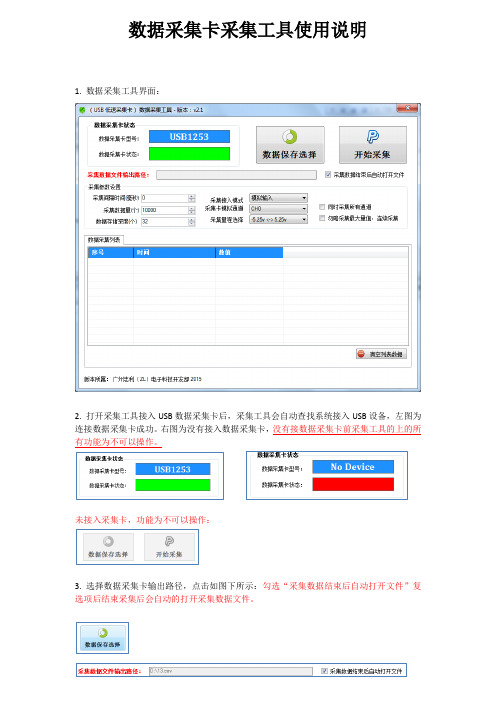
数据采集卡采集工具使用说明1. 数据采集工具界面:2. 打开采集工具接入USB数据采集卡后,采集工具会自动查找系统接入USB设备,左图为连接数据采集卡成功。
右图为没有接入数据采集卡,没有接数据采集卡前采集工具的上的所有功能为不可以操作。
未接入采集卡,功能为不可以操作:3. 选择数据采集卡输出路径,点击如图下所示:勾选“采集数据结束后自动打开文件”复选项后结束采集后会自动的打开采集数据文件。
4. 采集参数设置:A.采集间隔时间(毫秒):采集每次数据点之间的等待时间设置,设置为0表示不等待连续采集数据。
B.采集数据量(个):最大采集数量值,采集到最大值后程序自动停止结束。
勾选“勿略采集最大量值,连续采集”复选框后此设置将无效。
采集结束在点击“停止采集”按键后结束。
C.数据存储深度(个):存储深度主要解决实时显示数据软件所占用的时间,存储深度值越大显示数据越慢,此显示速度慢不影响正常采集速度,只是影响显示速度。
如采集时频率比较慢时需要设置采集间隔时间,把存储深度设置为1表示实时值。
D.采集接入模式:采集模拟分为三种:模拟输入(单极性),差分输入,真双极输入。
模拟输入只能采集大于0V以上的电压值,不能采集负电压。
差分输入可以测试正负电压,测试正负电压需要按差分方式接线,差分方式接线与地线无关。
真双极输入可以测试正负电压,可以直接测试负电压。
采集工具会根据采集卡类型显示不同的输入模式,工具只会显示支持的模式选择项。
详细支持输入模式请参考产品说明书参数规格。
E.采集卡输入通道:输入通道表示采集卡指定的采集通道,不同型号采集有不同数量的采集通道。
采集卡支持:单通道采集和全通道采集功能。
全通道采集功能可以勾选“同时采集所有通道”复选框。
F.采集量程选择:不同类型采集卡支持不同的量程选择,详细参数可以参考用户说明。
5.清空列表数据点击“清空列表数据”按键后会清除列表数据,注意:清空后的数据不可恢复:6.数据采集:点击“开始采集”按键后采集工具自动开始采集数据,点击“停止采集”后程序自动停止并保存采集数据。
NI板卡数据手册
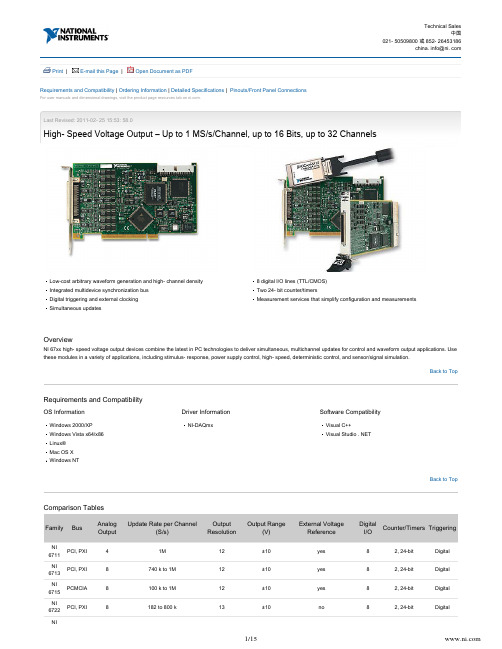
Back to TopBack to Top| | Print E-mail this Page Open Document as PDFLast Revised: 2011-02- 25 15:53: 58.0High- Speed Voltage Output – Up to 1 MS/s/Channel, up to 16 Bits, up to 32 ChannelsLow-cost arbitrary waveform generation and high- channel density Integrated multidevice synchronization bus Digital triggering and external clocking Simultaneous updates8 digital I/O lines (TTL/CMOS)Two 24- bit counter/timersMeasurement services that simplify configuration and measurementsOverviewNI 67xx high- speed voltage output devices combine the latest in PC technologies to deliver simultaneous, multichannel updates for control and waveform output applications. Use these modules in a variety of applications, including stimulus- response, power supply control, high- speed, deterministic control, and sensor/signal simulation.Requirements and CompatibilityOS InformationWindows 2000/XP Windows Vista x64/x86Linux®Mac OS X Windows NTDriver InformationNI-DAQmxSoftware CompatibilityVisual C++Visual Studio . NETComparison TablesFamilyBusAnalog OutputUpdate Rate per Channel(S/s)Output ResolutionOutput Range(V)External Voltage ReferenceDigital I/OCounter/Timers TriggeringNI 6711PCI, PXI 41M 12±10yes 82, 24-bit Digital NI 6713PCI, PXI 8740 k to 1M 12±10yes 82, 24-bit Digital NI 6715PCMCIA 8100 k to 1M 12±10yes 82, 24-bit Digital NI 6722PCI, PXI8182 to 800 k13±10no82, 24-bitDigitalNIBack to Top6723PCI, PXI 3245 to 800 k13±10no 82, 24-bit Digital NI 6731PCI 41M 16±10yes 82, 24-bit Digital NI 6733PCI, PXI8740 k to 1M13±10yes82, 24-bitDigitalApplication and TechnologyFeaturesThe versatile NI high- speed voltage output devices commonly replace several kinds of instruments including stand- alone proportional integral derivative (PID) controllers, low-speed arbitrary waveform generators, and function generators.Waveform GenerationThese devices are capable of updating at rates up to 1 MS/s, giving you the ability to generate waveforms up to 500 kHz. When using these devices, you have complete control of each data point that is updated on the output for each channel. This feature is significant because you can define not only common waveforms such as square, sine, or sawtooth but also complex waveforms. For instance, you are able to create a sine wave that is overlaid with noise in which the amplitude and noise shape are user- defined. In practice, the waveform is defined in a software buffer, within PC memory, and is streamed to the voltage output device using direct memory access (DMA) data transfers. Using DMA transfers,the amount of memory located on board the voltage output device is minimized and swapped with inexpensive PC memory.Real- Time ControlYou can use NI high- speed voltage output devices with the NI LabVIEW Real- Time Module to deliver real- time, deterministic control loop execution. Because they arecompatible with LabVIEW Real- Time, common control algorithms such as PID are simple to implement but, more importantly, you may prototype and implement complex, cutting-edge control algorithms as well. High- performance control, on the order of eight PID loops running in excess of 20 kHz each, is possible with this combination of hardware and software. Each high- speed voltage output device offers multichannel simultaneous updates and hardware- timed single- point updates.Multidevice SynchronizationEach high- speed voltage output device offers the ability to be master or slave of a multidevice timing and triggering system. Use integration technologies such as the RTSI bus,PXI trigger bus, and PFI pins to trigger and synchronize to a wide variety of I/O types. These I/O types range from analog input, image acquisition, motion control, and high- speed digitizers to multifunction data acquisition devices. With these integration infrastructures, you can create powerful, custom test and control systems with ease.Measurement Services SoftwareNational Instruments measurement services software, built around NI-DAQmx driver software, features intuitive application programming interfaces, configuration tools, I/O assistants, and other tools designed to reduce system setup, configuration, and development time. This software,part of your data acquisition purchase, includes helpful features such as:Automatic code generation – The DAQ Assistant is an interactive guide that helps you navigate through configuring, testing, and programming analog output tasks and automatically generates the necessary code for NI LabVIEW, LabWindows/CVI, and Measurement Studio software.Cleaner code development – Basic and advanced software functions have been combined into one easy-to- use yet powerful set to help you build cleaner code and move from basic to advanced applications without replacing functions.High- performance driver engine – NI- DAQmx delivers maximum I/O system throughput with a multithreaded driver.Test panels – With the NI Measurement & Automation Explorer (MAX) configuration utility, you can test all of your module functionality before you begin development.Scaled channels – Easily scale your voltage data into the proper engineering units using the NI- DAQmx measurement- ready virtual channels by choosing from a list of common sensors and signals or creating your own custom scale .LabVIEW integration – All NI-DAQmx functions create the waveform data type, which carries acquired data and timing information directly into more than 400 LabVIEW built-in analysis routines for display of results in engineering units on a graph.NI-DAQmx Base DriverNI-DAQmx Base (available at ) offers Mac OS X and Linux users a programming interface similar to NI- DAQmx. It features ready-to- use LabVIEW VIs and C ni. com/downloads function features similar to those included in NI- DAQmx driver software.NI DAQCard- 6715 Hardware Block DiagramNI 671x and NI 673x Hardware Block DiagramNI 672x Hardware Block DiagramHigh- Speed Voltage Output Cables and Accessories Recommended ConfigurationsShielded options for minimal noise interferenceDirect connectivity options such as BNCLow-cost options for OEMFront- mount terminal block for PXICustom connectivity with the CA-1000I/O Connector BlocksBNC-2110 – Shielded I/O connector block with signal- labeled BNC connectors for easy connectivity of your analog output (AO), digital I/O (DIO), and counter/timer signals. Dimensions – 20.3 by 11.2 by 5.5 cm (8.0 by 4.4 by 2.2 in.)BNC- 2110.............................................................................. 777643-01BNC-2115 – Shielded I/O connector block with signal- labeled BNC connectors for easy connectivity of your extended analog output on NI 6723 devices. Dimensions – 20.3 by 11.2 by 5.5 cm (8.0 by 4.4 by 2.2 in.)BNC- 2115.............................................................................. 777807-01SCB-68 – Shielded I/O connector block that gives you rugged, very low- noise signal termination. The SCB- 68 also houses silk- screened component locations for easy addition of simple signal conditioning circuitry for your AO channels. Dimensions – 19.5 by 15.2 by 4.5 cm (7.7 by 6.0 by 1.8 in.)SCB-68 .................................................................................. 776844-01CA-1000 – Configurable enclosure that gives you user- defined connectivity and flexibility through customized panelettes. Dimensions – 30.7 by 25.4 by 4.3 cm (12.1 by 10 by 1.7 in.)CA-1000 .............................................................................. 777664-01TBX-68 – 68 screw terminals for easy connection of field signals to 68- pin DAQ devices. It includes one 68- pin male connector for direct connection to 68- pin cables. The TBX-68 is mounted in a protective plastic base with hardware for mounting on a standard DIN rail. Dimensions – 12.50 by 10.74 cm (4.92 by 4.23 in.)TBX-68 .................................................................................. 777141-01CB-68LP, CB-68LPR – 68 screw terminals for easy connection of field signals to AO devices. They include one 68- pin male connector for direct connection to 68- pin cables. The connector blocks include standoffs for use on a desktop or for mounting in a custom panel. The CB- 68LP has a vertical mounted 68-pin connector. The CB- 68LPR has a right-angle mounted connector and can also be used with the CA-1000. Dimensions – 14.35 by 10.74 cm (5.65 by 4.23 in.); 7.62 by 16.19 cm (3.00 by 6.36 in.)CB-68LP ................................................................................ 777145-01CB- 68LPR............................................................................... 777145-02TB-2705 – 68- pin screw- terminal block for NI PXI- 671x and PXI-673x modules. Latches to the front of your PXI module with locking screws and provides strain relief as well as easy access to your analog, digital, trigger, and counter/timer signals through screw terminals. Does not work with NI 6703 or NI 6704 devices. Dimensions – 8.43 by 10.41 by2.03 cm (3.32 by4.1 by 0.8 in.)TB-2705 ................................................................................ 778241-01Synchronization CablesRTSI Bus Cables – Used to connect timing and synchronization signals among measurement, vision, motion, and CAN boards for PCI. For systems with long and short boards, use the extended RTSI cable.2 boards . . . . . . . . . . . . . . . . . . . . . . . . . . . . . . . . . . . . . . . 776249- 023 boards . . . . . . . . . . . . . . . . . . . . . . . . . . . . . . . . . . . . . . . 776249-034 boards . . . . . . . . . . . . . . . . . . . . . . . . . . . . . . . . . . . . . . . 776249-045 boards . . . . . . . . . . . . . . . . . . . . . . . . . . . . . . . . . . . . . . . 776249-05Extended, 5 boards . . . . . . . . . . . . . . . . . . . . . . . . . . . . . . . 777562-05Shielded I/O CablesSH68-68- EP – Shielded 68- conductor cable terminated with two 68-pin female 0.050 series D- type connectors, featuring individually shielded analog twisted pairs for reduced crosstalk with high- speed devices. This cable works with all NI 671x and NI 673x devices.1 m . . . . . . . . . . . . . . . . . . . . . . . . . . . . . . . . . . . . . . . . . . . . 184749-01SHC68-68- EP – Shielded cable for connecting and latching the NI DAQCard- 6715, NI 6722, and NI 6723 to standard 68-pin accessories. Latching screws secure the shielded connector to the device itself for stability. Use this cable for a DAQCard located in the bottom PCMCIA slot of a laptop.0.5 m . . . . . . . . . . . . . . . . . . . . . . . . . . . . . . . . . . . . . . . . . 186838- 0R51 m . . . . . . . . . . . . . . . . . . . . . . . . . . . . . . . . . . . . . . . . . .186838- 01SHC68U- 68-EP – Identical to the SHC68-68- EP except the DAQCard connector is inverted so you can use two latching DAQCard devices in adjacent slots. Use this cable with a DAQCard inserted in the upper PCMCIA slot of a laptop.Back to Top0.5 m . . . . . . . . . . . . . . . . . . . . . . . . . . . . . . . . . . . . . . . . . 187406- 0R51 m . . . . . . . . . . . . . . . . . . . . . . . . . . . . . . . . . . . . . . . . . . 187406-01SH68-C68- S – Shielded cable for connecting and latching NI 672x devices to standard 68-pin accessories.2 m . . . . . . . . . . . . . . . . . . . . . . . . . . . . . . . . . . . . . . . . . . . . 186381-02Ribbon I/O CablesR6868 – 68- conductor flat ribbon cable terminated with two 68-pin connectors. Use this cable to connect the NI 670x, NI 671x, and NI 673x devices to low- cost 68- pin accessories.1 m . . . . . . . . . . . . . . . . . . . . . . . . . . . . . . . . . . . . . . . . . . . . 182482-01RC68-68 – 68- conductor flat ribbon cable terminated with one VHDCI 68- pin connector and one 68-pin SCSI II connector. Use this cable to connect the NI 6722 devices and DAQCard- 6715 with standard 68-pin accessories.1 m . . . . . . . . . . . . . . . . . . . . . . . . . . . . . . . . . . . . . . . . . . . . 187252-01Ordering InformationFor a complete list of accessories, visit the product page on .ProductsPart Number Recommended Accessories Part NumberNI PCI- 6723NI PCI- 6723Requires: 2 Cable , 2 Connector Block778701-01Connector 0:Cable: Shielded - SH68- C68-S Cable (2m)186381-02 Connector Block: Spring- Screw_Terminals - SCB-68 **Also Available: BNC_Terminals 776844-01Connector 1:Cable: Shielded - SH68- C68-S Cable (2m)186381-02 Connector Block: Spring- Screw_Terminals - SCB-68 **Also Available: BNC_Terminals776844-01NI PCI- 6722NI PCI- 6722Requires: 1 Cables , 1 Connector Blocks778705-01Cables: Shielded - SH68- C68-S Cable (2m)186381-02Connector Blocks: Spring- Screw_Terminals - SCB-68 **Also Available: BNC_Terminals776844-01Back to TopBack to TopNI PXI- 6722NI PXI- 6722Requires: 1 Cable , 1 Connector Block778999-01Cable: Shielded - SH68- C68-S Cable (2m)186381-02Connector Block: Spring- Screw_Terminals - SCB-68 **Also Available: BNC_Terminals776844-01NI PXI- 6723NI PXI- 6723Requires: 2 Cable , 2 Connector Block778998-01Connector 0:Cable: Shielded - SH68- C68-S Cable (2m)186381-02 Connector Block: Spring- Screw_Terminals - SCB-68 **Also Available: BNC_Terminals 776844-01Connector 1:Cable: Shielded - SH68- C68-S Cable (2m)186381-02 Connector Block: Spring- Screw_Terminals - SCB-68 **Also Available: BNC_Terminals776844-01Software Recommendations用于Windows 的LabVIEW专业版开发系统用于开发大型项目的 高级软件使用DAQ助手 (DAQ Assistant) 和仪器I/O助手(Instrument I/O Assistant) 自动生成代码与各种硬件紧密集成高级测量分析和数字 信号处理连通DLL、 ActiveX和. NET对象创建DLL、可执行 程序和MSI安装程 序NI LabWindows/CVI (Windows版)实时高级二维图形和 图表与IVI、 VISA、DAQ、 GPIB和串口,完全实现硬件兼容数组操作、信号处理 统计和曲线拟合的分析工具具有网络变量的简易 式跨平台通信LabWindows 标志由 Microsoft 公司授权测量工作室. NET工具NI Measurement Studio专业版支持针对 Microsoft Visual Studio . NET 2005/2008/2010可定制的 Windows Form和Web Form控件, 面向测试与测量用户界 面设计硬件集成支持, 搭 配数据采集和仪器控 制库自动代码生成, 搭 配数据采集、仪器控制和参数助手具有网络变量的跨平 台通信分析库适合数组运 算、信号生成、加窗、滤波器、信号处 理Support and ServicesSystem Assurance ProgramsNI system assurance programs are designed to make it even easier for you to own an NI system. These programs include configuration and deployment services for your NI PXI,CompactRIO, or Compact FieldPoint system. The NI Basic System Assurance Program provides a simple integration test and ensures that your system is delivered completely assembled in one box. When you configure your system with the NI Standard System Assurance Program, you can select from available NI system driver sets and application development environments to create customized, reorderable software configurations. Your system arrives fully assembled and tested in one box with your software preinstalled.When you order your system with the standard program, you also receive system- specific documentation including a bill of materials, an integration test report, a recommended maintenance plan, and frequently asked question documents. Finally, the standard program reduces the total cost of owning an NI system by providing three years of warranty coverage and calibration service. Use the online product advisors at ni. com/advisor to find a system assurance program to meet your needs.CalibrationNI measurement hardware is calibrated to ensure measurement accuracy and verify that the device meets its published specifications. NI offers a number of calibration services to help maintain the ongoing accuracy of your measurement hardware. These services allow you to be completely confident in your measurements, and help you maintain compliance to standards like ISO 9001, ANSI/NCSL Z540-1 and ISO/IEC 17025. To learn more about NI calibration services or to locate a qualified service center near you,contact your local sales office or visit ni. com/calibration.Technical SupportGet answers to your technical questions using the following National Instruments resources.Support - Visit ni. com/support to access the NI KnowledgeBase, example programs, and tutorials or to contact our applications engineers who are located in NI sales offices around the world and speak the local language.Back to TopDiscussion Forums - Visit forums. for a diverse set of discussion boards on topics you care about.Online Community - Visit community. to find, contribute, or collaborate on customer- contributed technical content with users like you.RepairWhile you may never need your hardware repaired, NI understands that unexpected events may lead to necessary repairs. NI offers repair services performed by highly trained technicians who quickly return your device with the guarantee that it will perform to factory specifications. For more information, visit ni. com/repair.Training and CertificationsThe NI training and certification program delivers the fastest, most certain route to increased proficiency and productivity using NI software and hardware. Training builds the skills to more efficiently develop robust, maintainable applications, while certification validates your knowledge and ability.Classroom training in cities worldwide - the most comprehensive hands-on training taught by engineers.On-site training at your facility - an excellent option to train multiple employees at the same time.Online instructor- led training - lower- cost, remote training if classroom or on- site courses are not possible.Course kits - lowest- cost, self- paced training that you can use as reference guides.Training memberships and training credits - to buy now and schedule training later.Visit ni. com/training for more information.Extended WarrantyNI offers options for extending the standard product warranty to meet the life- cycle requirements of your project. In addition, because NI understands that your requirements may change, the extended warranty is flexible in length and easily renewed. For more information, visit ni. com/warranty.OEMNI offers design- in consulting and product integration assistance if you need NI products for OEM applications. For information about special pricing and services for OEM customers, visit ni. com/oem.AllianceOur Professional Services Team is comprised of NI applications engineers, NI Consulting Services, and a worldwide National Instruments Alliance Partner program of more than 600 independent consultants and integrators. Services range from start-up assistance to turnkey system integration. Visit ni. com/alliance.Detailed SpecificationsThis document lists the specifications for the NI 6722/6723 analog output devices. The following specifications are typical at 25 °C unless otherwise noted.Note With NI- DAQmx, National Instruments has revised its terminal names so they are easier to understand and more consistent among NI hardware and softwareproducts. The revised terminal names used in this document are usually similar to the names they replace. For a complete list of Traditional NI-DAQ terminal names and their NI- DAQmx equivalents, refer to the Terminal Name Equivalents section of Chapter 2, , of the .I/O Connector Analog Output Series User Manual Analog OutputOutput Characteristics Number of channels NI 6722 8 voltage outputs NI 6723 32 voltage outputs Resolution13 bits, 1 in 8,192Max update rateNumber of ChannelsMax Update RateUsing Local FIFO (kS/s) 1Using Host PC Memory (kS/s) 21800800271471484761821633390.924253603220445Type of DAC Double- buffered, voltageFIFO buffer size 2,047 samplesDMA channels 3Data transfers DMA, interrupts, programmed I/ODMA modes Scatter- gatherAccuracy InformationNominal Range at Full Scale (V)Absolute Accuracy% of Reading Offset (mV)Temp Drift (% /°C)Absolute Accuracy at Full Scale (mV)24 Hours90 Days 1 Year±100.0335%0.0355%0.0377%±7.0100.0005%10.78Absolute accuracy = (% of Reading × Voltage) + Offset + (Temp Drift × Voltage) Note: Temp drift applies only if ambient is greater than ±10 °C of previous external calibration.Transfer CharacteristicsRelative accuracy (INL) ±2.0 LSB maxDNL ±0.9 LSB maxMonotonicity 13 bitsVoltage OutputRange ±10 VOutput coupling DCOutput impedance 0.1 Ω maxCurrent drive ±5 mA maxOutput stability Any passive loadProtection Short- circuit to groundPower-on state 0 V (±200 mV)External Reference InputRange ±11 VOvervoltage protection ±27 V powered on, ±12 V powered offInput impedance 10 kΩDynamic CharacteristicsSlew rate 0.7 V/μsNoise 1.0 mV, DC to 1 MHzrmsChannel crosstalk – 65 dB with SH68-C68- S cable (generating a 10 V, 100 point sinusoidal at 100 kHz on the reference channel)Settling time 45 μs typ, 55 μs max to ±0.5 LSBGlitch energy (at mid- scale transition)Magnitude 400 mVDuration 2 μsChannel- to- channel update glitchMagnitude 100 mVDuration 1.2 μsNote Channel- to- channel update glitch is the energy glitch that occurs on all channels as the result of a channel update. For example, if you update the value of Channel 7, all other channels will experience this glitch regardless of whether their output voltages change.StabilityCalibrationRecommended warm-up time 15 minCalibration interval 1 yrOnboard calibration referenceLevel 5.000 V (±2.5 mV) (actual value stored in EEPROM)Temperature coefficient ±5.0 ppm/°C max Long- term stability ±15 ppm/√1, 000 h Digital I/ONumber of channels 8 input/output Compatibility TTL/CMOSDigital logic levelsLevel Min MaxInput low voltageInput high voltageInput low current (V = 0 V)inInput high current (V = 5 V)in 0 V2.0 V——0.8 V5.0 V–320 μA10 μAOutput low voltage (I = 24 mA)OLOutput high voltage (I = –13 mA)OH —4.35 V0.4 V—Power-on state Input (high- impedance)Data transfers Programmed I/OTiming I/ONumber of channels 2 up/down counter/timers, 1 frequency scaler ResolutionCounter/timers 24 bitsFrequency scaler 4 bitsCompatibility 5 V TTL/CMOSBase clocks availableCounter/timers 20 MHz, 100 kHzFrequency scaler 10 MHz, 100 kHzBase clock accuracy ±0.01%Max external source frequencyFrequency scaler 20 MHzExternal source selections PFI <0.. 9>, RTSI <0..6>External gate selections PFI <0.. 9>, RTSI <0..6>Min source pulse duration 10 ns, edge- detect modeMin gate pulse duration 10 ns, edge- detect modeData transfersUp/down counter/timers DMA (scatter- gather), interrupts, programmed I/O Frequency scaler Programmed I/ODMAChannels 1 (scatter- gather)Data source/destination Analog output, counter/timer 0, counter/timer 1 TriggersDigital TriggerPurposeAnalog output Start trigger, gate, clockCounter/timers Source, gateSource PFI <0.. 9>Compatibility 5 V TTLResponse Rising or falling edgePulse width 10 ns minRTSI Bus (PCI Only)Trigger lines <0..6> 7RTSI clock 1PXI Trigger Bus (PXI Only)Trigger lines <0..5> 6Star trigger 1Clock 1Bus InterfaceNI PCI- 6722/6723 3.3 V or 5 V PCI master, slave NI PXI- 6722/6723 PXI/CompactPCI master, slave Power Requirement+3.3 VDC (±5%) 300 mA+5 VDC (±5%) 1.5 A typ, 3 A max (not including power sourced from +5 V pin on I/O connector)Power available at I/O connector +4.65 to +5.25 VDC at 1 APhysicalDimensions (not including connectors)NI PCI- 6722/6723 17.4 × 9.8 cm (6.85 × 3.85 in.)NI PXI- 6722/6723 16 × 10 cm (6.3 × 3.9 in.)I/O connectorNI 6722 1 68-pin VHDCINI 6723 2 68-pin VHDCIMaximum Working VoltageMaximum working voltage refers to the signal voltage plus the common- mode voltage.Channel- to-earth ±11 V, Installation Category IChannel- to- channel ±22 V, Installation Category IEnvironmentalThe NI 6722/6723 is intended for indoor use only.Operating temperature 0 to 50 ° CStorage temperature –20 to 70 °CHumidity 5 to 90% RH, noncondensingMaximum altitude 2,000 metersPollution Degree 2Note Clean the device with a soft, non- metallic brush. Make sure that the device is completely dry and free from contaminants before returning it to service. SafetyThis product is designed to meet the requirements of the following standards of safety for electrical equipment for measurement, control, and laboratory use: IEC 61010-1, EN 61010- 1UL 61010- 1, CSA 61010-1Note For UL and other safety certifications, refer to the product label or the section.Online Product CertificationElectromagnetic CompatibilityThis product is designed to meet the requirements of the following standards of EMC for electrical equipment for measurement, control, and laboratory use: EN 61326 EMC requirements; Minimum ImmunityBack to TopEN 55011 Emissions; Group 1, Class ACE, C- Tick, ICES, and FCC Part 15 Emissions; Class ANote For EMC compliance, operate this device with shielded cabling.CE ComplianceThis product meets the essential requirements of applicable European Directives, as amended for CE marking, as follows:73/23/EEC; Low- Voltage Directive (safety)89/336/EEC; Electromagnetic Compatibility Directive (EMC)Note Refer to the Declaration of Conformity (DoC) for this product for any additional regulatory compliance information. To obtain the DoC for this product, visit ni., search by model number or product line, and click the appropriate link in the Certification column.com/certification Online Product CertificationRefer to the product Declaration of Conformity (DoC) for additional regulatory compliance information. To obtain product certifications and the DoC for this product, visit ni., search by module number or product line, and click the appropriate link in the Certification column.com/certification Waste Electrical and Electronic Equipment (WEEE)EU Customers At the end of their life cycle, all products be sent to a WEEE recycling center. For more information about WEEE recycling centers and National must Instruments WEEE initiatives, visit .ni. com/environment/weee. htm 1These numbers apply to continuous waveform generation, which allows for the fastest waveform generation because it does not use the PCI bus. The max update rate in FIFO mode does not change regardless of the number of devices in the system. The NI 6722/6723 does not take any time to reset the FIFO to the beginning when cycling through it.2These results were measured using a PCI- 6722/6723 device with a 550 MHz Pentium III machine. These numbers may change when using more devices or when other CPU or bus activity occurs.Pinouts/Front Panel ConnectionsNI 6722 68-Pin AO I/O Connector Pin AssignmentsNI 6723 68-68- Pin Extended AO I/O Connector Pin AssignmentsBack to Top©2009 National Instruments. All rights reserved. CompactRIO, CVI, DAQCard, FieldPoint, LabVIEW, Measurement Studio, MITE, National Instruments, National Instruments Alliance Partner, NI, ni. com, and RTSI are trademarks of National Instruments. The mark LabWindows is used under a license from Microsoft Corporation. Windows is a registered trademark of Microsoft Corporation in the United States and other countries. Other product and company names listed are trademarks or trade names of their respective companies. A National Instruments Alliance Partner is a business entity independent from National Instruments and has no agency, partnership, or joint- venture relationship with National Instruments.| | | |我的个人信息RSS隐私权说明法律信息联系NI© 2012 National Instruments Corporation. All rights reserved.。
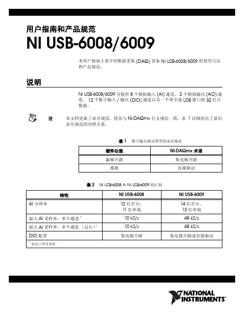
NI USB6008 6009 用户指南
行的测量。该类别需参见当地配电标准 (例如,标准壁装插座电源在
美国为 115 V,在欧洲为 230 V)。此类测量包括家用电器、便携式工
具和类似设备的测量。
• Measurement Category III 适用于在建筑物设施中进行的测量。此类
1 电气设备安全标准 IEC 61010-1 对测量类别进行了分类,测量类别也称为安装类别。
2 工作电压是指任何绝缘体上可能存在的最大交流电压有效值或直流电压值。
3 MAINS 是指为设备提供电力的危险带电供电系统。符合条件的电路也可连至用于测量目的的 MAINS 系统。
NI USB-6008/6009 用户指南和产品规范
数据采集设备开发虚拟仪器、数据采集和设备控制应用程序。点击开始 »
程序 »National Instruments»NI-DAQ»NI-DAQmx C Reference Help
查看文档。
.NET 语言,未安装 NI 应用软件
如已安装 Microsoft .NET Framework 1.1 或更高版本,可在 NI-DAQmx 中使用 Visual C# 和 Visual Basic .NET 编程语言创建应用程序 (无需 Measurement Studio)。 API 文档需安装 Microsoft Visual Studio .NET 2003 或 Microsoft Visual Studio 2005。
设备工作环境的污染等级应小于等于二级。污染是指固态、液态或气态杂 物,它会降低设备的绝缘强度或表面电阻率。污染等级说明如下:
• 污染等级 1 是指无污染或仅有干燥的、非导电性污染。此污染无影响。 • 污染等级 2 是指大多数情况下,仅产生非导电性污染。但需考虑偶然由
NI最新推出一系列USB数据采集卡
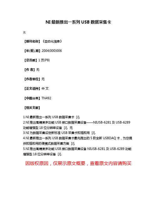
NI最新推出一系列USB数据采集卡
无
【期刊名称】《自动化信息》
【年(卷),期】2004(000)006
【总页数】1页(P8)
【作者】无
【作者单位】无
【正文语种】中文
【中图分类】TN492
【相关文献】
1.NI最新推出一系列USB数据采集卡 [J],
2.NI推出高精度多功能USB接口数据采集设备——NIUSB-6281及USB-6289功能增强型18位分辨率设备 [J], 无
3.NI为数据采集设定新标准 USB采集卡即插即用 [J],
4.NI最新推出一系列USB数据采集卡最先推出的5款全新USBDAQ卡,为您提供即插即用的便携式数据采集方案 [J],
5.NI推出高精度多功能USB接口数据采集设备NIUSB-6281及USB-6289功能增强型18位分辨率设备 [J],
因版权原因,仅展示原文概要,查看原文内容请购买。
NI数据采集(DAQ)设备入门指南说明书

DAQ Getting Started GuideThis guide describes how to confirm your NI data acquisition (DAQ) device is operating properly. Install your application and driver software, then your device, using the instructions packaged with your device. Confirm Device RecognitionComplete the following steps:unch MAX by double-clicking the NI MAX icon on the desktop, or (Windows8) by clickingNI MAX from NI Launcher.2.Expand Devices and Interfaces to confirm your device is detected. If you are using a remoteRT target, expand Remote Systems, find and expand your target, and then expand Devices andInterfaces. If your device is not listed, press <F5> to refresh the configuration tree. If the device isstill not recognized, refer to /support/daqmx.For a Network DAQ device, do the following:•If the Network DAQ device is listed under Devices and Interfaces»Network Devices, right-click it and select Add Device.•If your Network DAQ device is not listed, right-click Network Devices, and select Find Network NI-DAQmx Devices. In the Add Device Manually field, type the Network DAQdevice’s host name or IP address, click the + button, and click Add Selected Devices. Yourdevice will be added under Devices and Interfaces»Network Devices.Note If your DHCP server is set up to automatically register host names, the device registers thedefault host name as cDAQ-<model number>-<serial number>, WLS-<serial number>,or ENET-<serial number>. You can find the serial number on the device. If you cannot find thehost name of that form, it may have been modified from the default to another value.If you still cannot access your Network DAQ device, click the Click here for troubleshootingtips if your device does not appear link in the Find Network NI-DAQmx Devices window orgo to /info and enter the Info Code netdaqhelp.Tip You can test NI-DAQmx applications without installing hardware by using an NI-DAQmxsimulated device. For instructions on creating NI-DAQmx simulated devices and importingNI-DAQmx simulated device configurations to physical devices, in MAX, select Help»Help Topics»NI-DAQmx»MAX Help for NI-DAQmx.3.Right-click the device and select Self-Test. When the self-test finishes, a message indicates successfulverification or if an error occurred. If an error occurs, refer to /support/ daqmx.4.For NI M and X Series PCI Express devices, right-click the device and select Self-Calibrate.A window reports the status of the calibration. Click Finish.Configure the Device SettingsSome devices, such as the NI-9233 and some USB devices, do not need properties for configuringaccessories, RTSI, topologies, or jumper settings. If you are installing only devices without configurable properties, skip to the next step. Configure each device with configurable settings that you install:1.Right-click the device name and select Configure. Be sure to click the device name under thefolder for the system (My System or Remote Systems) and NI-DAQ API in which you want tocontrol the device.For Network DAQ devices, click the device name and then the Network Settings tab to configurenetwork settings. For additional information on configuring Network DAQ devices, refer to yourdevice documentation.2.Configure the device properties.•If you are using an accessory, add the accessory information.•For IEEE 1451.4 transducer electronic data sheet (TEDS) sensors and accessories, configure the device and add the accessory as previously described. Click Scan for TEDS. To configureTEDS sensors cabled directly to a device, in MAX, right-click the device under Devices andInterfaces and select Configure TEDS.3.Click OK to accept the changes.Install Signal Conditioning or Switch DevicesIf your system includes SCXI signal conditioning modules, Signal Conditioning Components (SCC)such as SC carriers and SCC modules, terminal blocks, or switch modules, refer to the getting started guide for the product to install and configure the signal conditioning or switch hardware.Attach Sensors and Signal LinesAttach sensors and signal lines to the terminal block or accessory terminals for each installed device.You can find device terminal/pinout locations in MAX, the NI-DAQmx Help, or the devicedocumentation. In MAX, right-click the device name under Devices and Interfaces, and selectDevice Pinouts.For information about sensors, refer to /sensors. For information about IEEE 1451.4 TEDS smart sensors, refer to /teds. If you are using SignalExpress, refer to Use NI-DAQmx withYour Application Software.Run Test PanelsUse the MAX test panel as follows.1.In MAX, expand Devices and Interfaces or Devices and Interfaces»Network Devices.2.Right-click the device to test, and select Test Panels to open a test panel for the selected device.3.Click the tabs at the top and Start to test the device functions, or Help for operating instructions.4.If the test panel displays an error message, refer to /support.5.Click Close to exit the test panel.DAQ Getting Started Take an NI-DAQmx MeasurementNI-DAQmx Channels and TasksA physical channel is a terminal or pin at which you can measure or generate an analog or digital signal.A virtual channel maps a name to a physical channel and its settings, such as input terminal connections,the type of measurement or generation, and scaling information. In NI-DAQmx, virtual channels areintegral to every measurement.A task is one or more virtual channels with timing, triggering, and other properties. Conceptually, a taskrepresents a measurement or generation to perform. You can set up and save configuration information in a task and use the task in an application. Refer to the NI-DAQmx Help for complete information about channels and tasks.Use the DAQ Assistant to configure virtual channels and tasks in MAX or in your application software. Configure a Task Using the DAQ Assistant from MAXComplete the following steps to create a task using the DAQ Assistant in MAX:1.In MAX, right-click Data Neighborhood and select Create New to open the DAQ Assistant.2.In the Create New window, select NI-DAQmx Task and click Next.3.Select Acquire Signals or Generate Signals.4.Select the I/O type, such as analog input, and the measurement type, such as voltage.5.Select the physical channel(s) to use and click Next. the task and click Finish.7.Configure individual channel settings. Each physical channel you assign to a task receives a virtualchannel name. To modify the input range or other settings, select the channel. Click Details forphysical channel information. Configure the timing and triggering for your task. Click Run. Use NI-DAQmx with Your Application SoftwareThe DAQ Assistant is compatible with version 8.2 or later of LabVIEW, version 7.x or later ofLabWindows™/CVI™ or Measurement Studio, or with version 3 or later of SignalExpress.SignalExpress, an easy-to-use configuration-based tool for data logging applications, is at Start»AllPrograms»National Instruments»NI SignalExpress or (Windows8) NI Launcher.To get started with data acquisition in your application software, refer to the tutorials:Application Tutorial LocationLabVIEW Go to Help»LabVIEW Help. Next, go to Getting Started with LabVIEW»GettingStarted with DAQ»Taking an NI-DAQmx Measurement in LabVIEW.LabWindows/CVI Go to Help»Contents. Next, go to Using LabWindows/CVI»Data Acquisition»Taking anNI-DAQmx Measurement in LabWindows/CVI.Measurement Studio Go to NI Measurement Studio Help»Getting Started with the Measurement StudioClass Libraries»Measurement Studio Walkthroughs»Walkthrough: Creating aMeasurement Studio NI-DAQmx Application.SignalExpress Go to Help»Taking an NI-DAQmx Measurement in SignalExpress.© National Instruments3DAQ Getting Started GuideExamplesNI-DAQmx includes example programs to help you get started developing an application. Modifyexample code and save it in an application, or use examples to develop a new application or add example code to an existing application.To locate LabVIEW, LabWindows/CVI, Measurement Studio, Visual Basic, and ANSI C examples, go to /info and enter the Info Code daqmxexp. For additional examples, refer to .To run examples without hardware installed, use an NI-DAQmx simulated device. In MAX, selectHelp»Help Topics»NI-DAQmx»MAX Help for NI-DAQmx and search for simulated devices. TroubleshootingIf you have problems installing your software, go to /support/daqmx. For hardwaretroubleshooting, go to /support and enter your device name, or go to /kb.If you need to return your National Instruments hardware for repair or device calibration, refer to / info and enter the Info Code rdsenn to start the Return Merchandise Authorization (RMA) process.Go to /info and enter rddq8x for a complete listing of the NI-DAQmx documents and their locations.More InformationAfter you install NI-DAQmx, the NI-DAQmx software documents are accessible from Start»All Programs»National Instruments»NI-DAQ»NI-DAQmx document title or(Windows8) NI Launcher. Additional resources are online at /gettingstarted.You can access online device documentation by right-clicking your device in MAX and selecting Help»Online Device Documentation. A browser window opens to /manuals with the results of a search for relevant device documents. If you do not have Web access, documents for supported devices are included on the NI-DAQmx media.Worldwide Technical SupportFor support information, refer to /support for access to everything from troubleshooting and application development self-help resources to email and phone assistance from NI ApplicationEngineers. Visit /zone for product tutorials, example code, webcasts, and videos.Visit /services for NI Factory Installation Services, repairs, extended warranty, calibration, and other services.To ensure measurement accuracy, NI factory calibrates all applicable hardware and issues a BasicCalibration certificate, which you can get online at /calibration.Visit /training for self-paced training, eLearning virtual classrooms, interactive CDs,Certification program information, or to register for instructor-led, hands-on courses at locations around the world.For support available at the National Instruments worldwide offices, visit , or contact your local office at /contact. National Instruments corporate headquarters is located at 11500 NorthMopac Expressway, Austin, Texas, 78759-3504.DAQ Getting Started Refer to the NI Trademarks and Logo Guidelines at /trademarks for more information onNational Instruments trademarks. Other product and company names mentioned herein are trademarksor trade names of their respective companies. For patents covering National Instrumentsproducts/technology, refer to the appropriate location: Help»Patents in your software, thepatents.txt file on your media, or the National Instruments Patent Notice at /patents.You can find information about end-user license agreements (EULAs) and third-party legal notices inthe readme file for your NI product. Refer to the Export Compliance Information at /legal/export-compliance for the National Instruments global trade compliance policy and how toobtain relevant HTS codes, ECCNs, and other import/export data.© 2003–2013 National Instruments. All rights reserved.373737H-01Jul13。
用NI的数据采集卡实现简单电子测试之1——USB-6009简介
⽤NI的数据采集卡实现简单电⼦测试之1——USB-6009简介本⽂从本⼈的163博客搬迁⾄此。
⼏年以来,⼀直担任学校“虚拟仪器”课程教师。
以前上课都以介绍LabVIEW编程为主,硬件实验⼀直没有开展。
这次借“西部⾼校实⼒提升⼯程”的机会,学院采购了⼀批NI的数据采集卡,终于有机会让学⽣动⼿开展⼀点硬件实验了。
这次采购的是⼊门级的USB数据采集卡——USB-6009,NI没有为这卡提供外围实验电路,要⽤他上实验课还得⾃⼰动⼿为这个“⼩宝贝”设计⼏个实验,并配些外围电路。
接下来的⼏篇博⽂,将分⼏次介绍为学⽣设计的实验及外围电路,写到哪算哪吧。
今天先从⼩宝贝⼯具USB-6009介绍起。
(NI官⽅⽹站上介绍资料的内容就不原样重复了,只把我觉得有⽤、有趣和⼤家会感兴趣的内容摘⼀下)在NI众多的数据采集卡中,USB-6009可以算是性能最低的了,价格也相对最低——官⽅渠道约⼩3000元(个⼈觉得还是⽐国产的其他数据采集卡还是贵多了)。
USB-6009性能不⾼,但“⿇雀虽⼩,五脏俱全”,常见的功能⼀应俱全,基本能够体现LabVIEW+NI数据采集卡的开发特点。
先来张外观照⽚。
再看看内部电路板(PCB的顶层,底层没东西)。
⼀、USB-6009的内部构成打开后盖,看到USB-6009主要有两个芯⽚,⼀个是Silicon Labs的单⽚机,另⼀个是TI的⼗四位ADC,这两个芯⽚决定了USB-6009的基本性能。
单⽚机上的激光丝印看不出它的型号,但“Silicon Labs”、“TQFP-32封装”、“有USB DEVICE接⼝”⼏个条件⼀综合,⼤概能猜出来了:C8051F320——2.3KB RAM+16KB Flash。
TI的ADS7871是个功能挺全⾯的ADC。
四个全差分通道,或变为⼋个单端通道。
其他参数包括:14位分辨率;带有⽚上PGA;参考电压等都和USB-6009⼀样。
个⼈觉得这个ADC最⼤的缺点就是最⾼采样率只有48KBPS。
usb数据采集卡V53使用说明书

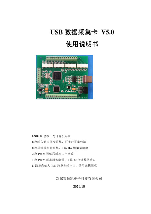
USB 数据采集卡V5.3使 用 手 册新郑市恒凯电子科技有限公司2016/9USB2.0总线AD 采集模块 4路同步单端输入16位 200KHz AD,192K FIFO 缓冲 2路12位DA,无缓冲16路单向输入口/16路单向输出口 2路32位PWM、单脉冲发生器2路32位PWM 等精度测量输入在开始使用前请仔细阅读下面说明检查打开包装请查验如下:USB数据采集卡V5.3一块20线电缆及接口板各一套。
安装将数据采集卡插入主机的任何一个USB2.0插槽中并将外部的输入、输出线连好。
如果主机USB电源供应能力差,请连接附送的电源。
保修本产品自售出之日起一年内,用户遵守储存、运输和使用要求,而产品质量不合要求,凭保修单免费维修。
因违反操作规定和要求而造成损坏的,需缴纳器件费及相应的运输费用,如果板卡有明显烧毁、烧糊情况原则上不予维修。
如果板卡开箱测试有问题,可以免费维修(限购买板卡10天内)。
软件支持服务自销售之日起提供6个月的免费开发咨询。
(如有刊误,敬请批评指正!)目录目 录 (2)一、USB数据采集卡V5.3说明 (4)USB数据采集卡V5.3板简介 (4)特点: (4)主要特点 、性能: (5)AD部分: (5)DA输出 (5)开关量输入输出及计数器 (5)软件支持: (6)其他特性 (6)二、原理说明 (7)2-1:模拟输入AI及模拟输出AO (7)AD数据排列 (7)AD数据转换 (7)内部定时器时钟与外部时钟 (8)触发开始采样 (8)过采样及相关说明 (8)2-2:开关量部分的原理: (12)2-3:PWM及单脉冲输出原理 (12)PWM方波输出 (12)单次脉冲输出(SP模式,软件触发单稳态输出) (13)2-5:模拟输出DA (13)三、安装与连接 (14)3-1:安装 (14)关于USB (14)USB延长线 (14)3-2:信号连接注意事项 (14)3-3:连接器插座定义 (15)16 DIN定义: (15)16 DOUT定义: (16)3-4:配套端子板 (16)四、软件 (18)4-1:软件安装与说明 (18)软件说明 (18)驱动安装 (18)测试软件安装 (22)4-2:接口函数说明 (25)设备操作函数 (25)AD操作函数 (25)DA操作函数 (28)PWM及脉冲输出函数 (28)PWM 测量函数 (29)单向开关量输入操作函数 (29)单向开关量输出操作函数 (29)4-3:VC程序编程说明 (32)4-4 Labview程序编程说明 (33)一、USB数据采集卡V5.3说明USB数据采集卡V5.3板简介USB数据采集卡V5.3是一款基于USB总线的高性能多功能数据采集卡,具有4路单端16位高速同步模拟信号采集(最高同步采样速率200KSPS,同步采样即每通道都是200KSPS)、2路12位模拟信号输出(只有单次低速输出模式)、16路数字信号单向输入/16路数字信号单向输出、2路32位PWM等精度测量输入、2路32位PWM或单脉冲输出。
USB6009数采卡的说明

USB-6009数采卡介绍1.简介NI 公司的USB-6009数采卡提供8个模拟输入通道,2个模拟输出通道,12位的数字I/O 口,以及一个32位计数器,它与电脑通过USB 接口连接。
使用USB-6009数采卡之前,首先按照图1进行组装,然后安装必要的驱动程序,具体过程,参考NI-DAQmx 软件的安装。
①端口类别及标号②接插件③标签(需粘帖)④USB 接口线图1 USB-6009数采卡USB-6009数采卡1~16号端子是模拟输入输出端子排,17~32号端子是数字输入输出端子排。
具体端子定义参见下图2、3,及表1、表2。
图2 模拟信号端子排表1 模拟信号端子排定义图3 数字信号端子排表2 数字端子排定义2.性能参数及基本构造1)模拟量输入:各模拟信号输入后,经过图4电路进行处理图4 模拟输入通道输入的模拟信号Analog Input ,经过多路选择器与PGA (Programmable-Gain Amplifier 增益可设放大器,PGA 的增益在差分输入时,根据输入电压范围自动在1、2、4、5、8、10、16上调整,而在单端输入是,固定为1)连接,经放大的信号经过ADC转换成数字信号,存储在FIFO(First In First Out)存储器中。
这里,可以设定PFI 0端为数字触发输入。
在数字触发模式下,模拟信号采集会在PFI 0端上升沿后进行。
主要性能参数:ADC-----逐次比较型ADC输出-----差分输入14位,单端输入13位模拟输入信号-----8路单端输入、4路差分输入,由软件设定最大采样率-----48KS/s输入电压范围-----单端±10V差分±20V, ±10V, ±5V, ±4V, ±2.5V, ±2V,±1.25V, ±1V输入阻抗-----144Kohm2)模拟量输出:模拟信号输出电路如图5示图5 模拟输出通道USB 6009有两个独立的Analog Output模拟输出通道,可输出0~5V 电压。
usb数据采集卡使用说明书V2.0
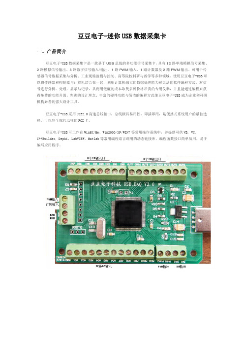
豆豆电子-迷你USB数据采集卡一、产品简介豆豆电子-USB数据采集卡是一款基于USB总线的多功能信号采集卡,具有12路单端模拟信号采集、2路模拟信号输出、8路数字信号输入/输出、1路PWM输入、1路计数器及2路PWM输出。
可用于传感器信号数据采集与分析、工业现场监测与控制、高等院校科研与教学等多种领域。
使用豆豆电子-USB可以将传感器和控制器与计算机结合在一起,利用计算机强大的数据处理能力和灵活的软件编程方式,对信号进行分析、处理、显示与记录,从而用低廉的成本取代多种价格昂贵的专用仪器,并且能通过编程来获得免费的功能升级。
先进的设计理念、丰富的硬件功能与简洁的编程方式使豆豆电子-USB成为企业和科研机构必备的强大设计工具。
豆豆电子-USB采用USB2.0高速总线接口,总线极具易用性,即插即用,是便携式系统用户的最佳选择,可以完全取代以往的PCI卡。
豆豆电子-USB可工作在Win9X/Me、Win2000/XP/WIN7等常用操作系统中,并提供可供VB, VC,C++Builder, Dephi,LabVIEW,Matlab等常用编程语言调用的动态链接库,编程函数接口简单易用,易于编写应用程序。
单位:mm二、性能指标2.1、USB总线性能●USB2.0高速总线传输●使用方便,能够实现自动配置,支持设备的热插拔即插即用2.2、模拟信号输入●模拟输入通道: 12路单端●输入端口耐压: 0—3.3V●输入信号量程: 0—3.3V●模拟输入阻抗: 10M●分辨率: 12Bit(4096)●最大总误差: < 0.2%●采样时钟: 100sps-100Ksps内部时钟(多通道50K)2.3、模拟信号输出●模拟输出通道: 2路单端(同步)●模拟输出范围: 0-3.3V●模拟输出电流: 1毫安●分辨率: 12Bit(4096)●非线性误差: ±2LSB●扫描时钟: 1sps-1000Ksps内部时钟2.4、数字信号输入/输出●输入/输出通道: 8路●输入/输出模式: 全输入/全输出●输入电平: 兼容TTL或CMOS●输出电平: CMOS2.5、PWM测量输入●个数: 1●输入电压: 0-3.3V●输入频率: 1—1MHz●输入占空比: 1%--99%●频率及占空比测量误差:1%2.6、计数器●计数器个数: 1●输入电平: TTL或CMOS●计数位: 32位(最大65535*65535)2.7、PWM输出●PWM输出通道: 2●PWM输出电平: CMOS●输入占空比:1%--99%●输出频率:1—1MHz2.8、工作温度●0℃ - 70℃三、应用领域便携式仪表和测试设备传感器信号采集与分析工业控制四、软件支持提供Windows95/98/NT/2000/XP/WINDOWS 7(32bit)下的驱动程序,提供通用DLL文件,并提供在LabVIEW和LabWindows图像化语言编写的应用软件范例程序。
数据采集卡说明指导书

PC-6311D模入模出接口卡技术阐明书1.概述:PC-6311D 模入模出接口卡合用于具备ISA 总线PC系列微机,具备较好兼容性,CPU从当前广泛使用64位解决器直到初期16位解决器均可合用,操作系统可选用典型MS-DOS,当前流行Windows系列,高稳定性Unix等各种操作系统以及专业数据采集分析系统 LabVIEW 等软件环境。
在硬件安装上也非常简朴,使用时只需将接口卡插入机内任何一种ISA总线插槽中,信号电缆从机箱外部直接接入。
也可插入我所研制PC扩展箱内使用。
PC-6311D模入模出接口卡安装使用以便,程序编制简朴。
其模入模出及I/O信号均由卡上37芯D型插头及另配转换插头与外部信号源和设备连接。
对于模入某些,顾客可依照实际需要选取单端或双端输入方式。
对于模出某些,顾客可依照控制对象需要选取电压或电流输出方式以及不同量程。
2. 重要技术参数:2.1 模入某些2.1.1输入通道数:(标*为出厂原则状态,下同)单端32路;* / 双端16路2.1.2输入信号范畴:0V~10V*;/ ±5V2.1.3输入阻抗:≥10MΩ2.1.4A/D转换辨别率:12位2.1.5A/D转换速度:10μS2.1.6A/D启动方式:程序启动/外触发启动2.1.7A/D转换结束辨认:程序查询/中断方式2.1.8A/D转换非线性误差:±1LSB2.1.9A/D转换输出码制:单极性原码*/双极性偏移码2.2.10系统综合误差:≤0.2% FSR2.2 模出某些:2.2.1输出通道数:2路 (互相独立,可同步或分别输出,具备上电自动清零功能。
)2.2.2输出范畴:电压方式:0~5V;0~10V*;±5V;±2.5V电流方式:0~10mA;4~20mA2.2.3输出阻抗:≤2Ω (电压方式)2.2.4D/A转换器件:DAC12102.2.5D/A转换辨别率:12位2.2.6D/A转换输入码制:二进制原码(单极性输出方式时)*;二进制偏移码(双极性电压输出方式时)2.2.7D/A转换综合建立时间:≤2μS2.2.8D/A转换综合误差:电压方式:≤0.2% FSR电流方式:≤ 1% FSR2.2.9电流输出方式负载电阻范畴:使用机内+12V电源时:0~250Ω外加+24V电源时:0~750Ω2.3 数字量输入输出某些:2.3.1DI:8路;TTL原则电平2.3.2 DO:8路;TTL原则电平;有输出锁存功能2.4 电源功耗:+5V(±10%)≤400mA;+12V(±10%)≤100mA;-5V(±10%)≤10mA2.5 使用环境规定:工作温度:10℃~40℃;相对湿度:40%~80%;存贮温度:-55℃~+85℃2.6 外型尺寸:(不含档板)长×高=182.6mm×106.7 mm (7.2英寸×4.2英寸) 3. 工作原理:PC-6311D模入模出接口卡重要由模数转换电路、数模转换电路、数字量输入输出电路、接口控制逻辑电路构成。
NI 数据采集卡使用说明书
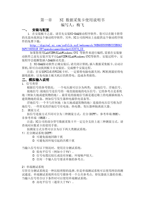
第一章 NI 数据采集卡使用说明书编写人:梅飞一、 安装与配置1. 在安装板卡之前,请首先安装NI-DAQ驱动程序软件。
您可以在随卡附带的光盘内找到这个驱动程序软件。
另外,NI公司的网站上也提供这个驱动程序软件的免费下载:/softlib.nsf/websearch/90B60D5899BCCCDB86256FC700581B 89?opendocument&node=132070_US如果您使用LabVIEW或LabWindows/CVI 等软件来进行编程,需要在安装驱动软件之前先安装开发平台LabVIEW或LabWindows/CVI等软件。
安装过程中,安装程序会提醒您插入DAQ驱动光盘。
2. NI-DAQ驱动软件正确安装后,请关闭计算机,插入数据采集板卡,启动计算机,即可自动找到板卡并安装好,完成整个安装过程。
注意:在安装PCI或者PXI板卡时,一定要将电脑电源关闭;PC机则最好将电源线拔掉,以免电脑主板关机后仍然带电,造成各类损伤。
二、模拟输入说明1. 信号类型根据信号的参考情况, 一个电压源可以分为两类: 接地信号、浮地信号。
接地信号:接地信号是信号的一端直接接地的电压信号。
它的参考点是系统地(例如大地或建筑物的地)。
最常见的接地信号源是通过墙上的电源插座接入建筑物地的设备,例如信号发生器和电源供电设备等。
浮地信号:一个不与任何地(如大地或建筑物的地)连接的电压信号称为浮地信号。
一些常见的浮地信号有电池、热电偶、变压器和隔离放大器。
2. 测量方式按信号连接方式不同可分为三种测量方式:差分(DIFF);参考单端(RSE);非参考单端(NRSE)。
注意:NI公司的部分型号数据采集卡不一定完全支持上述三种测量方式,请查询对应数采卡的使用手册。
按测量方式分类可以分为以下两大类测试系统:1)差分测试系统(DIFF)可避免接地回路干扰可避免因环境引起的共模干扰当输入信号有以下情况时,使用差分测试系统:低电平信号(例如小于1V)。
USB采集卡说明书
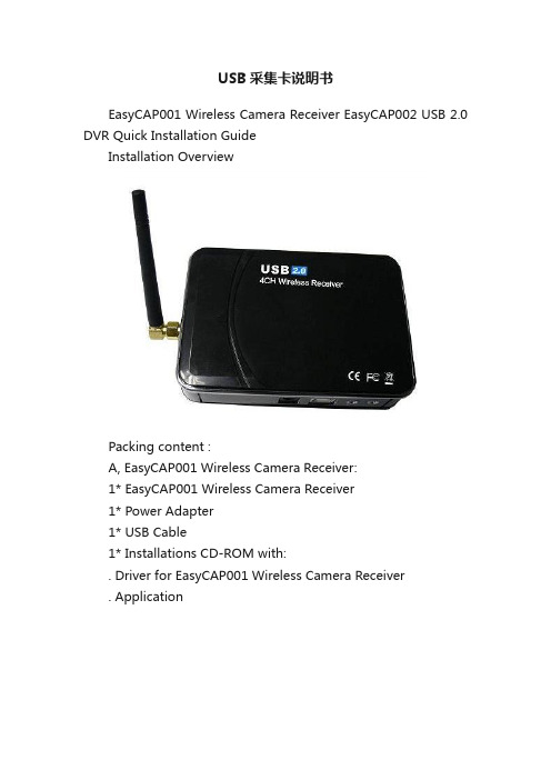
USB采集卡说明书EasyCAP001 Wireless Camera Receiver EasyCAP002 USB 2.0 DVR Quick Installation GuideInstallation OverviewPacking content :A, EasyCAP001 Wireless Camera Receiver:1* EasyCAP001 Wireless Camera Receiver1* Power Adapter1* USB Cable1* Installations CD-ROM with:. Driver for EasyCAP001 Wireless Camera Receiver. ApplicationB, EasyCAP002 USB 2.0 DVR1* EasyCAP002 USB 2.0 DVR1* Installations CD-ROM with:. Driver for EasyCAP002 USB 2.0 DVR. Application Connecting the EasyCAP001 Wireless Camera Receiver when you use it by TV, Monitor, or LCD Monitor: You must connect the Power Adapter to Wireless Camera Receiver when you use it by TV, Monitor, or LCD Monitor.(But no need this when you connect it to computer). And you can use Remote Controller to set any function (You can find the instruction for using remote controller in the bottom of this guide).Driver-Installationote: “If you have any anti-virus software enabled, please disable it during the installation of the software.”When you firstconnect the EasyCAP001 Wireless Camera Receiver ( or EasyCAP002 USB 2.0 DVR) to yourcomputer a Hardware Assistant will appear, the “USB 2.0 Video Capture Controller” will be recogni zed.Insert the “Installations CD-ROM” into your CD drive.Select the option “Install Driver” and click “Next”.If prompted “Can Windows connect to Windows Update to search for software?” select “No, not this time” and select “Next”. Select the option “I nstall the software automatically”and click “Next”.A window may appear about the “STK1160 ATV BDA” notpassing the windows logo testing, select “Continue Anyway”.When “Completing the Found New Hardware wizard” windowappears click the “Finish” button to complete the driverinstallation.ote: ”If any further components are found please repeat the NNabove process until you receive the message “Found newhardware: Your hardware is installed and configured use”You will now need to check that The drivers are installed correctly.Right Click on My Computer and Left Click on Properties. Click on Hardware tab and then Device Manager.In the “Device Manager”, click on the “+symbol”on the“Sound Video and Game controllers”section. If thedriver is installed correctly you should see the “STK1160ATV BDA”. If it has a Yellow mark next to it then thismeans that the driver is not installed correctly. You willneed to remove the driver and disconnect theEasyCAP001 Wireless Camera Receiver ( orEasyCAP002 USB 2.0 DVR) from the computer and re-connect is to install the driver again.Software InstallationTo start the Application Installation, click Start / Run then type your CD-ROM and click “Install.Select your language for the installation and Click “Next” or / and“Install”.Click “finish” to complete setup, restart your computer if needed.Run MultiViewer which you just installed.Introduction MultiViewerMultiViewerMultiViewer is a 4-channel wireless video surveillance software for Windows. It has advanced video viewer separate algorithm, various alert functions including schedule timer sanp, channel control, and sound. It can handle up to 4-channels video input, captures images up to 30 frames per second from USB video capture device. It uses be installed in Windows's video encoder and audio encoder , high quality video and audio effect , record file format A VI. The files can played with Windows Media Player or Real Player etc. JPEG image snapshots can be made from video images. Other features include secure Manual Control Channel,audio listening etc.Features1.Send e-mails attachment with image.2.Save image on Hard Disk.3.Sound alarm.4.Video signal filter, for filtrate Active and Invalid chunnel.5.Signal lost alarm.6.Motion Detection.7.Adjustable sensitivity.8.Automatically lock, while not any operate.9.Schedule Monitoring sessions, for timer snap.10.Record video/audio(with usb2.0 audio interface),snap shot.11.Automatic Space Managment. Stop recorder or capture still automatically on disk full.12.Support 4 Channel Video input on one computer.13.Support On Screen Display. Displys date and time ,or channel description on video.14.Supports manual open/close Invalid channel, or add/delete channel description.15.Supports login and logout, by UserName and Password.16.Supports running background stealthy.System requirementsWindows 2000/XP or better1.7GHz CPU or better128M memory or betterMicrosoft DirectX 9.0CUSB2.0 InterfaceAudio Card / True Color VGA CardMULTIVIEWER APPLICATION USER GUIDEThe MultiViewer Application can be started by clicking on the MultiViewer icon or by using the Start menu. The Following window should appear:A. Viewer Mode - Select viewer mode, such as Four Viewer, Big & Four Viewer and Single Viewer.B. Viewer Window - Show video image.C. Audio Play - For audio remote listening, with USB2.0 Audio interface .D. Login&Logout - Login and Logout the MultiViewer, by Username and Password.E. Camera/Channel Selection - Click the buttion,select Camera/Channel.F. Auto turning foucs - Click the "ON" buttion to enable, and click the "OFF" buttion to disable.G. Channel Settings -Such as channel description, channel active/inactive etc.H. System Settings - Adjust video recorder settings, such as Save A VI File Path etc.I. Record -Start and end video recordJ. Property - Advanced Settings video picture settings and fine tuning.K. Show Stamp -Show MultiViewer's system information,such as channel description, etc.L. Timer Snap - Captures and saves a bitmap picture after Schedule end.Timer adjustable by clicking on have file options button. Ref. N)M. Snap Shot -Capture and saves an instant bitmap picture.N. Save File - Settings Schedule for timer snap, displays and allows capture of destination path and filename of bitmap capture file.O. Security&Surveillance - Include E-Mail Sever Setup, Motion Detction Setup, Signal Lost Setup, Sensitivity Setup, and Auto Logout Setup.Schedule Timer Capture Still1. Settings Timer Snap Schedule and Save Image File Path [*](ref. N in Figure1)2. Click on Timer snap Button (ref. L in Figure1)(Note. Default files will be saved under MultiViewer installing folder. Such as: C:\Program Files\MultiViewer\Picture ) [*] Default Settings as follows Figure :Video Capturing1. Click on the Recorder button to begin recording. (ref. I in Figure1).2. To stop recording click on the same button.3. Output file path [*] can be changed by clicking the System button ( ref. H in Figure1)[*] Default files will be saved under MultiViewer installing folder. Such as: C:\Program Files\MultiViewer\Video Channul SettingsYou can select the video channel active or inactive by simply selecting CH1 of the CH4 options. You can add chunnel description in the viewer screen. The default setting as follows Figure :If you seletc the "Manual" button, MultiViewer will immediately stop control video channel, and main panel as showIf you click the "Reset" button, MultiViewer will start signal fiter for search the video channel again, and main panel as showNote:You can click the "SEARCH" button, to stop search the video channel.Security&Surveillance SettingsYou can select the motion detection, signal loset alarm, auto logout active or inactive by simply selecting the options. You can adjust the sensibility. The setting as follows Figure :If you select the "Open alarm sound" button, MultiViewer open alarm while condition active, and main panel as showNote:[1]You an click the "ALARM" button, to stop play sound.[2]Default still will be saved under MultiViewer installingfolder. Such as C\Program Files\MultiViewer\Picture\Motion. Advanced SettingsThe advanced settings window allows the user to adjust image characteristics by clicking on the Camera Controls tab. Camera Controls T abUse the picture property window shown below to adjust picture quality. By sliding the Control Adjust Bar the effect can be seen immediately on the viewer window. These setting can be saved by clicking the save button or cancelled by restoring thedefault settings.Check Box control features include:- NTSC, PAL, Vertical Flip, Mirror Flip and Backlight Composition.Instruction of remote controller (EasyCAP001)Note: The remote control only work for control the hardware device, not for the application of this device. Please do not use the channel auto-view function with both application and remote control at same time.When you connect the device to computer, or with power supply to connect to other show monitor with AV-IN, the greenlight will on, click the “power” button on the remote controller, the green light will be off, it means the device will be controlled by remote, and in this situations, the application wont control the channel selection if you connect the device to computer. (So, we do not suggest you use remote controller when you connect this device to computer).Key functionsPower on/off: only works for when using power adaptor.CH1~CH4: to select the 1~4 channel on.Auto: stop/start channel auto-view, automatically select CH1-CH2-CH3-CH4, then CH1...The default speed is 1 time/second (you can also change the speed with using "CH1~CH4", for example: when you click "CH1" then click "Auto" the speed will be 1 time/second, CH2 for 2 time/second and so on...Set: If you do not want to view any channel(s) of your camera, because some reason or you do not have 4 cameras, you can choose to skip the channel(s) when you using channel auto-view function. Use "SET" key and “CH1~CH4” keys you can set the LED light on and off for channel1~channel4 to make the relevant channel(s) be skipped. (light on means the channel working light off means the channel is skipped)。
NI采集卡的多通道不同功能采集的配置操作方法
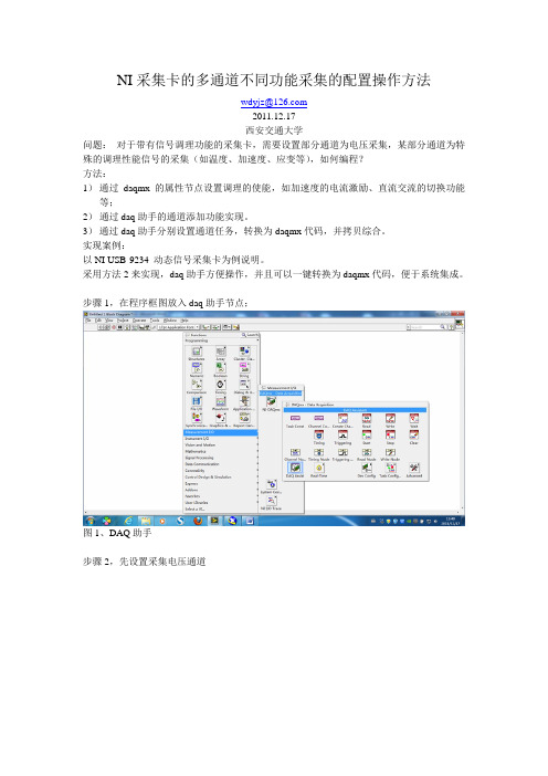
NI采集卡的多通道不同功能采集的配置操作方法
wdyjz@
2011.12.17
西安交通大学
问题:对于带有信号调理功能的采集卡,需要设置部分通道为电压采集,某部分通道为特殊的调理性能信号的采集(如温度、加速度、应变等),如何编程?
方法:
1)通过daqmx 的属性节点设置调理的使能,如加速度的电流激励、直流交流的切换功能等;
2)通过daq助手的通道添加功能实现。
3)通过daq助手分别设置通道任务,转换为daqmx代码,并拷贝综合。
实现案例:
以NI USB-9234 动态信号采集卡为例说明。
采用方法2来实现,daq助手方便操作,并且可以一键转换为daqmx代码,便于系统集成。
步骤1,在程序框图放入daq助手节点;
图1、DAQ助手
步骤2,先设置采集电压通道
图2、设置采集电压
步骤3,设置电压采集的具体参数
图3、电压采集参数设置(通道0)步骤4,添加加速度采集通道
图4、添加加速度采集通道
步骤5,设置加速度采集参数
图5、加速度通道参数采集设置步骤6,采集效果
图6、采集效果图
步骤7,转换为daqmx 代码
步骤8,转换后的效果。
USB视频采集卡使用说明书
其余三个 口均不接
2.测试线和采集卡的连接方法 测试线莲花头一端接在 USB 视频采集卡的黄色端子,另一端有 2 头
出线,分别是信号线(接 VTO)和地线,注意:测试线有 2 个出头,连 接时需要用万用表测一下导通;其中和莲花头外壳导通的接 GND,和 莲花头中心导通的接 VTO。
产品特性
◎ 支持 USB2.0,无需打开机箱,支持热插拔,支持笔记本电脑 ◎ 自行调整画面大小、最高分辨率可达 720×576,24 位真彩色 ◎ 最新技术 USB AUDIO、立体声输入输出 ◎ 图像亮度、对比度、饱和度、色度可自定义 ◎ 可捕捉高品质动态及静态画面,采集画面顺畅不间断 ◎ 输入接口有 AV 及 S 端子,可在台式机或手提电脑上观看录像、VCD、 DVD、摄像机等设备输出的视频影象 ◎ 支持 MPEG1/2 等多种实时压缩格式,方便制作 VCD/SVCD/DVD ◎ 兼容 WINDOW XP/Win7,兼容 Direct8.1、9.0
即在属性对话框中的 Image 标签下,选择“PAL/M”和“组合”选项, 确定后,即可在显示区看到摄像头图像了;如果此时还没有图像显示, 请调到第二步检查电气连接是否正确。
2.《USB 视频采集卡-Win7 版》
第一步 打开文件包,点击 Setup,进行软件安装。一直点击下 一步进行安装。
安装完成后,在桌面上回生成如下图所示的图标
插好 USB 视频采集卡,打开软件。如果 USB 视频采集卡没有插好, 或者 USB 口驱动电流不足,或者 USB 口接触松动,打开软件的时候会 出现以下错误:
更换 USB 口或者重新拔插几次,就可以打开软件了。如果重复几 次不可以打开软件,那么重新启动系统或者调到第三步重新安装软件 和驱动。
NI数据采集卡使用入门
NI数据采集卡使用入门NI (National Instruments) 数据采集卡是一种专门用于测量和记录各种类型的电信号、模拟信号和数字信号的硬件设备。
该采集卡被广泛应用于科研实验室、工业自动化和测试测量等领域。
本文将为您介绍如何使用NI数据采集卡进行基本的数据采集和分析。
首先,确保您已经安装了NI数据采集卡及其相关软件。
NI数据采集卡通常需要安装NI-DAQmx驱动软件以及LabVIEW开发环境。
安装完成后,您可以通过电缆将数据采集卡与被测设备连接起来。
接下来,我们需要编写一个简单的数据采集程序。
在LabVIEW中,您可以利用Drag-and-Drop编程的方式轻松构建这样的程序。
首先,打开LabVIEW软件并创建一个新的VI(Virtual Instrument)。
然后,从函数面板中拖放出一个“DAQ Assistant”组件。
在DAQ Assistant界面中,您可以选择数据采集卡的型号,并配置您希望测量的输入通道和参数。
在配置完成后,您需要添加数据保存和分析的功能模块。
您可以从函数面板中选择合适的函数模块,例如“Write to Measurement File”用于保存数据至文件,或者“Signal Processing”模块用于对数据进行处理和分析。
将这些功能模块拖放到主VI中,并根据需求进行参数配置。
在程序编写完成后,您可以通过点击LabVIEW界面中的运行按钮来启动数据采集和分析。
程序会使用预设的配置参数,自动从数据采集卡读取数据,并按照您的设置进行保存和分析。
此外,如果需要对数据进行实时的监测和显示,您可以在LabVIEW界面中添加相应的控件元素。
例如,您可以在Front Panel中添加一个Chart图表控件,用于实时显示采集到的数据。
同样地,您可以从函数面板中选择合适的控制模块,例如“Loop”结构来循环读取数据进行实时显示。
最后,当您完成数据采集和分析后,可以选择将数据保存至文件或者导出至其他软件进行进一步的处理。
usb数据采集卡使用说明书V50(新驱动)
USB数据采集卡 V5.0使用说明书USB2.0 总线,与计算机隔离8路输入通道同步采集,可实时采集传输8路单端模拟量采集,2路DA模拟量输出2路PWM可编程频率占空比输出1路PWM频率脉宽测量,1路32位计数器端口8 路单向输入口/8 路单向输出口,采用光耦隔离新郑市恒凯电子科技有限公司2015/10在开始使用前请仔细阅读下面说明检查打开包装请查验如下:¾USB数据采集卡 V5.0一块;¾高屏蔽USB数据传输电缆一根;保修本产品自售出之日起一年内,用户遵守储存、运输和使用要求,而产品质量不合要求,凭保修单免费维修。
因违反操作规定和要求而造成损坏的,需缴纳器件费及相应的运输费用,如果板卡有明显烧毁、烧糊情况原则上不予维修。
如果板卡开箱测试有问题,可以免费维修(限购买板卡10天内)。
软件支持服务自销售之日起提供6个月的免费开发咨询。
目录一、 USB 数据采集卡V5.0 说明 (1)1.1 板卡简介 (1)1.2 软件支持 (2)1.3 应用领域 (2)1.4 售后服务 (2)二、性能指标 (3)2.1 USB总线性能 (3)2.2 模拟信号输入 (3)2.3 模拟信号输出 (3)2.4 数字信号输入/输出 (3)2.5 PWM测量输入 (4)2.6 计数器 (4)2.7 PWM输出 (4)2.8、工作温度 (4)三、安装与连接 (5)3.1 安装 (5)3.1.1 关于USB (5)3.1.2 USB延长线 (5)3.2 信号连接注意事项 (5)3.4 端子定义及排序说明 (6)3.4 板子尺寸 (7)3.5 各类信号链接方式 (7)四、软件的安装与使用 (10)4.1 驱动的安装与软件的使用 (10)4.1.1 驱动的安装 (10)4.1.2 软件的使用 (12)4.2 接口函数说明 (16)4.2.1 设备操作函数 (16)4.2.2 AD操作函数概况 (17)4.2.3 其它输入输出操作函数 (20)4.2.4 多板卡同时使用相关函数 (23)4.2.5 过采样及相关说明 (24)五、客户程序使用采集卡教程 (28)5.1 VC编程教程 (28)5.2 编程教程 (28)5.3 LABVIEW编程教程 (29)5.4 Labwidows/CVI (32)一、 USB 数据采集卡V5.0 说明恒凯电子-USB数据采集卡采用USB2.0高速总线接口,总线极具易用性,即插即用,是便携式系统用户的最佳选择,可以完全取代以往的PCI卡。
- 1、下载文档前请自行甄别文档内容的完整性,平台不提供额外的编辑、内容补充、找答案等附加服务。
- 2、"仅部分预览"的文档,不可在线预览部分如存在完整性等问题,可反馈申请退款(可完整预览的文档不适用该条件!)。
- 3、如文档侵犯您的权益,请联系客服反馈,我们会尽快为您处理(人工客服工作时间:9:00-18:30)。
Industrial Digital I/O Device for USB –60 V, Channel-to-Channel IsolatedOverview and ApplicationsThe National Instruments USB-6525 is a full-speed USB device with eight normally open, channel-to-channel isolated, solid-state relay outputs and eight ±60 VDC channel-to-channel isolated digital inputs. The NI USB-6525 offers features for industrial control and manufacturing test applications, such as factory automation, embedded machine control, and production line verification. The solid-state relay outputs have a 60 VDC/30 V rms switching voltage and 500 mA/ch maximum switching current, making them ideal for controlling pumps, valves, motors, and other industrial actuators. The eight isolated digital input channels break ground loops and offer protection from noise and spikes on external signals. You can also use one of the digital input channels as a 5 kHz, 32-bit event counter for counting digital pulses.HardwareThe USB-6525 has eight channel-to-channel optically isolated inputs,P1.<0..7>, and eight channel-to-channel optically isolated, solid-state relay outputs, P0.<0..7>. The isolated inputs consist of an optocoupler, a depletion-mode MOSFET-based current-limiting circuit, and a Schottky diode. Each channel has its own positive and negative terminals capable of detecting a wide range of DC signals, from 5 V TTL logic levels to DC power supply levels up to 60 V.PFI 0 (an alias to P1.7) can also function as the source for a 32-bit counter. In this mode, the device counts low to high transitions on P1.7. You can arm and disarm the counter as well as read or reset the count through software.You can connect loads to the solid-state relay outputs with an AC or DC power source. The default power-on state of the solid-state relays is open. The relays also remain open when the computer and the USB-6525device are powered off.•Small, portable digital I/O device •Eight channel-to-channel optically isolated inputs (±60 VDC)•Eight channel-to-channel optically isolated, solid-state relay outputs (60 VDC/30 V rms max)•500 mA maximum switching current per channel•One 32-bit event counter•Full-speed USB (12 Mb/s) bus interface •Built-in, removable connectors for easy connectivity•USB cable strain relief Operating Systems•Windows Vista/XP/2000Recommended Software •LabVIEW•LabWindows™/CVI •Measurement Studio •LabVIEW SignalExpressOther Compatible Software •Visual Studio .NET•C, C++•Visual BasicMeasurement Services Software (included)•NI-DAQmx driver software •Measurement & Automation Explorer configuration utility•LabVIEW SignalExpress LEdata-logging softwareNI USB-6525IsolationIsolation is a form of built-in signal conditioning that provides an extended voltage range for direct connectivity to industrial sensors and actuators. The USB-6525 provides channel-to-channel isolation where each channel is physically and electrically separated from the others. Isolation provides three main benefits:1.Safety from hazardous high voltages and transients2.Rejection of common-mode voltages3.Removal of ground loopsSafety from High-Voltage TransientsIsolation electrically separates high-voltage front-end channels from each other and the low-voltage back end of the USB-6525. Signalsare passed between the two sections of the device using optocouplers. By separating the two sections, any voltages within the isolation specifications are prevented from entering the USB bus section or other channels. Isolation provides protection for the user, data acquisition system, and measurement data.Common-Mode Voltage RejectionA voltage common to both sides of a differential circuit pair iscalled common-mode voltage. This phenomenon is typical in noisy environments containing machinery and inductive loads. The differential voltage across the circuit pair is the desired signal, whereas the common voltage signal is the unwanted signal that may have been coupled into the transmission line. The USB-6525 can measure signals from lines with signal plus common-mode voltage of up to 60 VDC.Ground Loop RemovalGround loops are the most common source of noise in data acquisition applications. They occur when two connected terminals in a circuit are at different ground potentials, causing current to flow between thetwo points. This additional voltage can cause significant error in the measurement. When a ground loop exists, the measured voltage isthe sum of the signal voltage and the potential difference that exists between the signal source ground and the measurement system ground. This potential is generally not a DC level; therefore, the result is a noisy measurement system. By offering an isolated floating ground on the front end, the isolated USB-6525 devices are able to prevent ground loops from forming.SoftwareNational Instruments measurement services software, built aroundNI-DAQmx driver software, includes intuitive application programming interfaces, configuration tools, I/O assistants, and other tools designed to reduce system setup, configuration, and development time. National Instruments recommends using the latest version of NI-DAQmx driver software for application development in National Instruments LabVIEW, LabWindows/CVI, and Measurement Studio. To obtain the latest version of NI-DAQmx, visit /support/daq/versions. NI measurement services software speeds up your development with features including:•A guide to create fast and accurate measurements with no programming using DAQ Assistant•Automatic code generation to create your application in LabVIEW; LabWindows/CVI; LabVIEW SignalExpress; and Visual Studio .NET,C/C++/C#, or Visual Basic using Measurement Studio •Multithreaded streaming technology•More than 3,000 free software downloads to jump-start your project available at /zone•Software configuration of all digital I/O features without hardware switches/jumpers•Free LabVIEW SignalExpress LE data-logging softwareThe USB-6525 is compatible with the following versions (or later) of NI application software – LabVIEW, LabWindows/CVI, and Measurement Studio versions 7.x or LabVIEW SignalExpress. You can also use your NI digital I/O device with ANSI C, Microsoft Visual C++, Visual Basic, and the Microsoft .NET languages C# and Visual Basic .NET. The USB-6525 is not compatible with the Traditional NI-DAQ (Legacy) driver.Ordering InformationNI USB-6525..........................................................................779640-01 Includes NI-DAQmx software, LabVIEW SignalExpress LE data-logging software, anda USB cable.NI USB-6000 Series Prototyping Accessory........................779511-01 Includes breadboarding area with cover and strain relief.SpecificationsThese specifications are typical at 25 °C, unless otherwise noted.Isolated InputsNumber of channels............................8, ch-ch isolatedInput voltage range.............................-60 to 60 VDCDigital logic levelsInput current........................................ 3.0 mA/channel maxSolid-State Relay OutputsNumber of channels............................8, ch-ch isolatedRelay type...........................................Normally open solid-state relay(SSR)Switching voltage...............................60 VDC/30 V rms max Switching current (per channel).........500 mA max, full operationtemperature range Switching rate (90% duty cycle)......... 5 operations per second Relay open time..................................60 µs typRelay close time.................................. 1.2 ms typOn-resistance......................................550 mΩ, maxOff-leakage current (max)...................0.6 µA typCounterNumber of counters............................ 1 (P1.7 can be configured asa counter) Resolution...........................................32 bitsCounter measurements.......................rising edge counting Maximum input frequency.................. 5 kHzMinimum high pulse width.................20 µsMinimum low pulse width..................180 µsBus InterfaceUSB B 2.0 full-speed (12 Mb/s)Power RequirementsInput voltage....................................... 4.5 to 5.25 VDC in configuredstateActive current......................................150 mA maxSuspend current..................................350 µA typPhysical CharacteristicsDimensionsWithout connectors........................ 6.35 by 8.51 by 2.31 cm(2.50 by 3.35 by 0.91 in.)With connectors.............................8.18 by 8.51 by 2.31 cm(3.22 by 3.35 by 0.91 in.)I/O B series B receptacle,(2) 16 position (screw terminal)plug headers Screw-terminal wiring........................16 to 28 AWG copper conductorwire with 10 mm (0.39 in.) ofinsulation stripped from the end Torque for screw terminals.................0.22 to 0.25 N · m(2.0 to 2.2 lb in.)WeightWith connectors.............................Approx. 87 g (3.1 oz)Without connectors........................Approx. 64 g (2.3 oz)IsolationChannel-to-channel ............................60 VDC continuousChannel-to-earth ground ....................60 VDC continuous Withstand ..........................................60 VDC continuousNote:Do not use this module for connection to signals or for measurements within Measurement Categories II, III, or IV. EnvironmentNI 6528 and PXI-6529 devices are intended for indoor use only. Pollution degree (IEC-60664) (2)Operating EnvironmentAmbient temperature .........................0 to 55 °CRelative humidity................................10 to 90%, noncondensing Maximum altitude ..............................2,000 m at 25 °C ambienttemperature(tested in accordance with IEC-60068-2-1, IEC-60068-2-2, and IEC-60068-2-56)Storage EnvironmentAmbient temperature .........................-40 to 85 °CRelative humidity ...............................5% to 95%, noncondensing (tested in accordance with IEC-60068-2-1, IEC-60068-2-2, and IEC-60068-2-56)Safety and ComplianceSafetyThis product is designed to meet the requirements of the following standards of safety for electrical equipment for measurement, control, and laboratory use:•IEC 61010-1, EN 61010-1•UL 61010-1, CSA 61010-1Note:For UL and other safety certifications, refer to the product label or visit /certification, search by model number or product line, and click the appropriate link in the Certification column. Electromagnetic CompatibilityThis product is designed to meet the requirements of the following standards of EMC for electrical equipment for measurement, control, and laboratory use:•EN 61326 EMC requirements; Minimum Immunity•EN 55011 Emissions; Group 1, Class A•CE, C-Tick, ICES, and FCC Part 15 Emissions; Class ANote:For EMC compliance, operate this device according toproduct documentation.CE ComplianceThis product meets the essential requirements of applicable European Directives, as amended for CE marking, as follows:•73/23/EEC; Low-Voltage Directive (safety)•89/336/EEC; Electromagnetic Compatibility Directive (EMC) Note:Refer to the Declaration of Conformity (DoC) for this product for any additional regulatory compliance information. To obtain the DoC for this product, visit /certification, search by model number or product line, and click the appropriate link in the Certification column.Waste Electrical and Electronic Equipment (WEEE)EU Customers:At the end of their life cycle, all products must be sent to a WEEE recycling center. For more information about WEEE recycling centers and National Instruments WEEE initiatives, visit/environment/weee.htm.NI Services and SupportNI has the services and support to meet your needs around the globe and through the application life cycle – from planning and development through deployment and ongoing maintenance. We offer services and service levels to meet customer requirements in research,design, validation, and manufacturing. Visit /services .Training and CertificationNI training is the fastest, most certain route to productivity with our products. NI training can shorten your learning curve, save development time, and reduce maintenance costs over the application life cycle. We schedule instructor-led courses in cities worldwide, or we can hold a course at your facility. We also offer a professional certification program that identifies individuals who have high levels of skill and knowledge on using NI products. Visit /training .Professional ServicesOur NI Professional Services team is composed of NI applications and systems engineers and a worldwide National Instruments Alliance Partner program of more than 600 independent consultants andintegrators. Services range from start-up assistance to turnkey system integration. Visit /alliance .OEM SupportWe offer design-in consulting and product integration assistance if you want to use our products for OEM applications. For information about special pricing and services for OEM customers, visit /oem .Local Sales and Technical SupportIn offices worldwide, our staff is local to the country, giving you access to engineers who speak your language. NI delivers industry-leading technical support through online knowledge bases, our applications engineers, and access to 14,000 measurement and automationprofessionals within NI Developer Exchange forums. Find immediate answers to your questions at /support .We also offer service programs that provide automatic upgrades to your application development environment and higher levels of technical support. Visit /ssp .Hardware ServicesNI Factory Installation ServicesNI Factory Installation Services (FIS) is the fastest and easiest way to use your PXI or PXI/SCXI combination systems right out of the box.Trained NI technicians install the software and hardware and configure the system to your specifications. NI extends the standard warranty by one year on hardware components (controllers, chassis, modules)purchased with FIS. To use FIS, simply configure your system online with /pxiadvisor .Calibration ServicesNI recognizes the need to maintain properly calibrated devices for high-accuracy measurements. We provide manual calibration procedures, services to recalibrate your products, and automated calibration software specifically designed for use by metrology laboratories. Visit /calibration .Repair and Extended WarrantyNI provides complete repair services for our products. Express repair and advance replacement services are also available. We offerextended warranties to help you meet project life-cycle requirements. Visit /services.National Instruments • info@ • 800 813 3693*351494A-01*351494A-012007-8768-301-101-D。