工程力学英文版课件04 Equilibrium of a Rigid Body
Chapter 7 Equilibrium of a Rigid Body (Statics静力学)
Keyong Wang Department of Engineering Mechanics School of Mechanical Engineering Shanghai University of Engineering Science
2
7.1 Conditions for Rigid-body 7.2 Free-Body Diagram 7.3 Equations of Equilibrium 7.4 Two- and Three-Force Members 7.5 Constraints and Statical Determinacy
If this resultant force and couple moment are both equal to zero, then the body is said to be in equilibrium.
Mathematically, the equilibrium of a body is expressed as
Fig. 7-1 It is important to be able to determine the forces in the cables used to support this submarine to insure that they do not fail. In this chapter we will study how to apply equilibrium methods to determine the forces acting on the supports of a rigid body such as this.
3
CHAPTER OBJECTIVES
工程力学全英文Engineering Mechanics (30)
12
The Procedure of Analysis
to determine the relative displacement between two points A and B on axially loaded member 1. Internal Force
The method of sections; How to determine the location of the section?
Part II: Mechanics of Materials
Axial load
AXIAL LOAD
Average normal stress in axial loaded member
• The localization of the stress distribution
• The deformation of the axial loaded member • Analysis of indeterminate axial load member • Analysis of thermal stress and stress concentration • The stress on the inclined surface of an axial loaded member
If the force varies continuously along the member’s length, arbitrary location and P(x); If several constant external forces, each segment between any two external forces
AB 0
Since the end supports are fixed. Thus relative displacement of one end of the bar with respect to the other end to be equal to zero
结构力学(英) Chapter2 Equilibrium and Geometric Stability PPT精品课件

P1 m
A
m
a
XA
l
YA V
M
N
YA
V
M N
P2 P3 B
YB
YB
6
Statically Determinate Structures
P
A
C
B
a
RA Pb l
Pb / l
b l
RB
Pa l
P
Pa / l
Shear Diagram
The equations of statics alone are sufficient to compute the reactions and the distribution of internal forces.
M1 M2
+ Mx = M1,x M2,x = 0
z
+ My = M1,y M2,y = 0
+ Mz = M1,z M2,z = 0
x
3
Equilibrium of Planar Structure
4
External Forces
External Forces are the actions of other bodies to the structure under consideration.
n = number of structural components r = number of unknown reaction components If r = 3n, the structure is statically determinate If r > 3n, the structure is statically indeterminate
英汉双语弹性力学ppt课件
3
第二章 平面问题的基本理论
§2-1 平面应力问题与平面应变问题 §2-2 平衡微分方程 §2-3 斜面上的应力主应力 §2-4 几何方程刚体位移 §2-5 物理方程 §2-6 边界条件 §2-7 圣维南原理 §2-8 按位移求解平面问题 §2-9 按应力求解平面问题。相容方程 §2-10 常体力情况下的简化 §2-11 应力函数逆解法与半逆解法 习题课
无外力作用。
y
x
注意:平面应力问题z =0,但 问题相反。
ቤተ መጻሕፍቲ ባይዱz 0,这与平面应变
8
2.Plane strain problem Very long column bears the face force in parallel with plate face and doesn’t change
Elasticity
1
2
Chapter 2 The Basic theory of the Plane Problem
§2-1 Plane stress problem and plane strain problem
§2-2 Differential equation of equilibrium §2-3 The stress on the incline.Principal stress §2-4 Geometrical equation.The displacement of the rigid body §2-5 Physical equation §2-6 Boundary conditions §2-7 Saint-Venant’s principle §2-8 Solving the plane problem according to the displacement §2-9 Solving the plane problem according to the patible equation
工程力学英文版课件00 Introduction
Stability:
Capacity of a component or a structural element to retain the original state of equilibrium.
18
Under the requirement that the strength, rigidity, stability criteria are satisfied, provide the necessary fundamental theory and method of calculation for determining reasonable shape and dimension, choosing proper materials for the components with the most economic price.
21
Concentrated Force: A concentrated force represents the effect of a loading which is assumed to act at a point on a body. Force is defined as any action that tends to change the state of rest of a body to which it is applied. Three properties of force: Magnitude Direction Point of application
Transmissibility of Force The point of application of a force may be moved along its line of action without altering the effect of the force on any rigid body to which it is applied.
工程力学第四章PPT课件

力的平衡
总结词
力的平衡条件与平衡状态
详细描述
力的平衡是指物体在受到力的作用时,处于静止或匀速直线 运动的状态。平衡状态下的物体所受的合力为零,即合力矩 为零。在工程实践中,通过合理布置支撑、加强结构等措施 ,可以保证物体的平衡状态。
力的合成与分解
总结词
力的合成法则与力的分解法则
VS
详细描述
力的合成是指两个或多个力共同作用在物 体上,可以用一个等效的力来代替它们。 力的合成遵循平行四边形法则或三角形法 则。力的分解则是将一个力分解为两个或 多个等效的分力。力的合成与分解在解决 工程实际问题中具有重要意义。
案例三:建筑结构的抗震设计
总结词
抗震设计是确保建筑物在地震中保持稳定的关键因素 ,通过合理的抗震设计,可以减少建筑物在地震中的 损坏和人员伤亡。
详细描述
建筑结构的抗震设计主要考虑建筑物在地震作用下的动 态响应和稳定性。通过建立建筑物的动力学模型,可以 模拟建筑物在不同等级地震下的变形、应力和破坏情况 。这有助于工程师优化建筑物的结构设计、地基处理和 材料选择,提高建筑物的抗震性能和安全性。同时,抗 震设计还需要考虑建筑物的使用功能和成本效益等因素 ,以满足实际需求。
静力学还涉及到工程中的许多问题, 如物体的稳定性、压杆的稳定性等, 这些问题都需要通过静力学分析来解 决。
静力学在桥梁、建筑、机械等领域都 有广泛应用,例如建筑设计时需要计 算建筑结构的受力情况,以确保结构 的稳定性。
动力学应用
动力学主要研究物体运动状态的变化规律,包括运动物体的速度、加速度、力等物理量的分 析。
材料力学在土木工程、机械、航空航天等领域有广泛应用,例如桥梁和 建筑结构需要承受各种载荷的作用,机械零件也需要承受各种应力和应
工程力学全英文Engineering Mechanics (31)

Part II:Mechanics of MaterialsTorsionStudy object: A long straight member subjected to a torsional loading •How to determine the stress distribution?•How to determine the angle of twist?•Statically indeterminate analysis of the member in torsion?Torsion:If a member is subjected to the action of a pair of moments which are of a common magnitude and opposite senses,and lie in planes perpendicular to the longitudinal axis,the member is said to be in torsion.Screwdriver bar Transmission shaftTorque: a moment that tends to twist a member about its longitudinal axis. Shaft: a member that deforms mainly in torsion.Assumptions :•The cross section remains a plane,and the size and shape remain the same (a rigid plane).•The cross section rotates about the longitudinal axis through an angle.The small element on the surface is under pure shear:By observation :Longitudinal lines : remain straight , twisted angle;the length of shaft remains unchangedRadial lines : remain straight and rotate about the center of the cross sectionCircumferential lines : remain the same and rotate about the longitudinal axis TORSIONAL DFORMATION OF A CIRCULAR SHAFT t M tMAngle of twist : the relative angular displacement between two cross-sections,()x φ The angle of twist varies linearly with x .()x φφ∆The angle of twist of the back face: ()x φThe angle of twist of the front face: ()x φφ+∆causes the element to be subjected to a shear strain.Isolate an element from the shaft After deformation Before deformationIf andx dx ∆→d φφ∆→Since and are the same for all points on the cross section at x dφdxThe shear strain within the shaft varies linearly along any radial line from zero to .max γρd constant dx φ=at a specific position x c cdx d ///max γργφ==max γργ⎪⎭⎫ ⎝⎛=cImportant points (review)☐Assumptions:for a shaft with a circular cross section subjected to a torque.•The cross-section remains a plane•The length of the shaft and its radius remain unchanged•Its radial lines remain straight and circles remain circular☐The shear strain varies linearly along any radial line.r If the material is linear-elastic, then Hooke’s law applies, G τγ=A linear variation in shear strain leads to a corresponding linear variation in shear stress . The integral depends only on the geometry of the shaft.2max max A T dA J c c ττρ==⎰Polar moment of inertia max ()()A A T dA dA c ρρτρτ==⎰⎰Each element of area located at ,is subjected to aforce of .The resultant internal torque producedby this force is dA ρ()dT dA ρτ=()dF dA τ=TORSIONAL FORMULAmax γργ⎪⎭⎫ ⎝⎛=c max τρτ⎪⎭⎫ ⎝⎛=cT J ρτ=wheremaxτT :c :J :Torsional formulaPolar moment of inertia()cc A cd d dA J 0403022)41(222ρπρρπρπρρρ⎰⎰⎰====42c J π=Note: J is a geometric property of the circular area and is always positive. The commonunit is mm 4Solid shaft Tubular shaft ()4402i c c J -=πO 2cρρd d 2d =A O 2c i 2c 0ρρdThe internal torque T develops a linear distribution of shear stress along each radial line in the plane of the cross-section,it also develops an associated shear-stress distribution along an axial plane.Why?T Jρτ=The internal torque T develops a linear distribution of shear stress along each radial line in the plane of the cross-section,it also develops an associated shear-stress distribution along an axial plane.Why?(complementary property of shear stress))(x TAbsolute Maximum Torsional Stress of a shaft -A torque diagramThis diagram is a plot of the internal torque T versus its position x along the shaft length. Sign convention: By right-hand rule, if the thumb directs outward from the shaft, then the internal torque is positive.The Procedure of Analysis to determine the shear stress for a shaft under torsion1. Internal Loading (Torque)Section the shaft perpendicular to its axis at the point where the shear stress is to be e free-body diagram and the equilibrium equations to obtain the internal torque.2. Cross Section Properties (Polar moment of inertia )3. Shear Stress Distribution (Torsional formula)T J ρτ=42c J π=()4402i c c J -=πJTc =max τThe shaft is supported by two bearings and is subjected to three torques. Determine the shear stress developed at point A and B , located at section a-a of the shaft.Example 1ABInternal Torque.The bearing force reactions on the shaft are zero, since the applied torques satisfy moment equilibrium about the shaft’s axis.The free body diagram of the left segment.mkN T T m kN m kN M x ⋅==-⋅-⋅=1250030004250 ;0∑ABmkN T ⋅=1250AB Cross Sectional Property. The polar moment of inertia for the shaft is 474 )10(97.4) 75(2mm mm J ==πShear Stress. Since point A is at ρ=c = 75 mm and point B at ρ= 15 mmGPa mm kN mm mm m kN J Tc A 89.1/89.1)10(97.4)75)(1250(247==⋅==τGPa mmmm m kN J T B 377.0)10(97.4)15)(1250(47=⋅==ρτAns.Important points (review)☐For a linear elastic homogenous material, the shear stress along any radial line of the shaft varies linearly from zero to a maximum value at the outer surface.☐The shear stress is also linearly distributed along an adjacent axial plane of the shaft due to the complementary property of shear stress.☐Torsional formula:valid for a shaft with circular cross-section and made of homogenous material with a linear-elastic behavior.Deformation of the shaftdxd γφρ=(linear elastic material)d dxρφγ=)(/)(x J x T ρτ=Gx J x T )(/)(ργ=γτG =dxGx J x T d )()(=φANGLE OF TWISTdxGx J xT d )()(=φIntegrating over the entire length L of the shaft,⎰=Ldx Gx J x T 0)()(φTORSIONJGTL =φ∑=JGTL φConstant Torque and Cross-Sectional Area⎰=L dx Gx J x T 0)()(φ⎰=Ldx E x A x P 0)()(δAEPL =δ(Axially loaded bar)TTT 2T 1T 3Sign ConventionRight-hand rule,the torque and angle will be positive,provided the thumb is directed outward from the shaftTo determine the angle of twist of one end of a shaft with respect to the other end:1. Internal Loading (Torque)•The method of section and the equation of moment equilibrium2. Angle of Twist•The polar moment of inertia J (x );•or •A consistent sign convention for the shaftGdx x J x T )(/)(⎰=φJG TL /=φ✓If the torque varies continuously along the shaft’s length, a section should be made at the arbitrary position, T (x )✓If several constant external torques exist, the internal torques in each segment between any two external torques much be determined (a torque diagram)The Procedure of AnalysisExample 2The two solid steel shafts shown are coupled together using the meshed gears. Determine the angle of twist of end A of the shaft AB when the torque T=45N·m is applied.G=80GPa.Shaft AB is free to rotate within bearing E and F,whereas shaft DC is fixed at D.Each shaft has a diameter of20mm.1. Internal Torque. F ree body diagrams of the shafts are shown in figures. Step 1:Solution300Nm 150.0m/45N m 150.0/,0m 150.00=⋅===⨯-→=∑T F F T MABx ()()mN 5.22m 075.0N 003m 075.0,0-m 075.00⋅=⨯=⨯==⨯=F T T F Mx D x D CDx ∑→2. Angle of Twist.To solve the problem, we need to calculate the rotation of gear C with respect to the fixed end D in shaft DC .rad 0269.0]N/m )10(80[)m 010.0)(2/()m 5.1)(m N 5.22(294/+=⋅+==πφJG TL DC DC Since the two gears are in mesh, of gear C causes gear B to rotate C φBφrad0134.0 )m 075.0)(rad 0269.0()m 15.0(=→=B B φφm 010.0=c GPa80=GThen we need to determine the angle of twist of end A with respect to end B of shaft AB .The rotation of end A is therefore determined by adding and since bothangles are in the same direction .B φB A /φrad0.0850 rad 0.0716rad 0134.0/+=+=+=B B A A φφφAns.m 010.0=c GPa 80=G rad0134.0 =B φHomework assignments: 5-3, 5-9, 5-27, 5-38,5-58, 5-71()()()()()[]rad 0716.0m/N 1080m 010.02/m 2m N 45294/=⋅+==πϕJG TL AB BAEquilibrium:;0=--=∑B A xT T T MThere are two unknowns, therefore this problem is indeterminate.Compatibility or the kinematic condition: two ends are fixed:/=B A φSTATICALLY INDETERMINATE TORQUE-LOADED MEMBERS=-JGL T JG L T BC B AC A ()BC ACL LL +=⎪⎭⎫⎝⎛=L L T T BC A ⎪⎭⎫ ⎝⎛=L L T T AC B TORSION;0∑==B A xT T T M-- ;0=/BA φThe Procedure of AnalysisTo determine the unknown torques in statically indeterminate shafts:•Equilibrium equationsDraw a free-body diagram of the shaft to identify all internal torques.Write the equations of moment equilibrium about the axis of the shaft.•CompatibilityExpress the compatibility condition in terms of the rotational displacements caused by the reactive torques.•Solving unknownsSolve the equilibrium and compatibility equations for the unknown reactive torques.Pay attention to the sign of the results.Example 3The shaft is made from a steel tube,which is bonded to a brass core.A torque of T=250N·m is applied at its end,plot the shear-stress distribution along a radial line of its cross-section.(G st=80GPa,G br=36GPa)Solution:Equilibrium. A free-body diagram of the shaft . The reaction has been represented by twounknown amount of torques resisted by the steel, T st and by the brass, T br .m N 250=⋅+--br st T T Compatibility. The angles of twist at fixed end A should be the same for both the steel and brass since they are bonded together .brst φφφ==Applying the load-displacement relationship , , we haveJG TL /=φbrbr br st st st J G LT J G L T =brst T T 33.33=(1)(2)m N 28.7m N 72.242⋅=⋅=⇒br st T TThe shear stress in the brass core varies from zero at its center to the maximum at the interface, using the torsional formulaMPa 63.4mm)/2)(10(mm)mm/m)(10 m)(10N 28.7()(43max =⋅==πτbr br br J c T For the steel, the minimum shear stress is at this interfaceMPa 30.10])mm 10(mm) /2)[(20(mm) mm/m)(10 m)(10N 72.242()(443min=-⋅==πτst inner st st J c T The maximum shear stress is at the outer surfaceMPa 630.20])mm 10(mm) /2)[(20(mm)mm/m)(20 m)(10N 72.242()(443max =-⋅==πτst outer st st J c Tm N 28.7mN 72.242⋅=⋅=br st T Trad )10(1286.0N/mm)10(36N/mm 63.43232-===G τγAns.Homework assignments: 5-75, 5-82, 5-85The shear stress is discontinuous at the interface because the materials have different moduli .The stiffer material (steel)carries more shear stress.However,the shear strain is continuous at the interface.Shear strain at the interface:MPa63.4)(max =br τMPa30.10)(min =st τMPa630.20)(max =st τ。
工程力学课件(双语版)

(FS)
Sample problem 4-3 The spool in Fig. (a) weights 25N, and its center of gravity is located at the geometric center. The weight of block C is 50N. The coefficients of static friction at the two points of contact are as shown. Determine the largest horizontal force P that can be applied without disturbing the equilibrium of the system.
a. Static case (no P) No friction force, no relative motion, no tendency of relative motion. b. Static case (P <Fmax) No relative motion, but having the tendency of relative motion and a friction force existing. 0F =P<Fmax=SN S: coefficient of static friction c. Case of impending sliding (P=Fmax ) The surfaces on the verge of sliding. F =Fmax=SN d. Dynamic case (P>Fmax ) Surfaces sliding relative to each other. F=Fk=kN k: coefficient of kinetic friction s , k 的大小可由实验测定,它们与接触物体的材料和表 面状态有关。常用材料的s , k见表5-1。
工程力学专业外语60页PPT
Elastic Range: • Linear elastic: • Nonlinear elastic:
Plastic Range: • Yield point
• Yield strength • Ultimate strength
力学 mechanics 牛顿力学 Newtonian mechanics 经典力学 classical mechanics 静力学 statics 运动学 kinematics 动力学 dynamics 动理学 kinetics 宏观力学 macroscopic mechanics, macromechanics 细观力学 mesomechanics 微观力学 microscopic mechanics, micromechanics 一般力学 general mechanics 固体力学 solid mechanics 流体力学 fluid mechanics 理论力学 theoretical mechanics 应用力学 applied mechanics 工程力学 engineering mechanics 实验力学 experimental mechanics 计算力学 computational mechanics 理性力学 rational mechanics 物理力学 physical mechanics 地球动力学 geodynamics 分析力学 analytical mechanics
1. Stress and strain are related terms used to define the intensity of internal reactive forces in a deformed body and associated unit change of dimension, shape, or volume by externally applied forces.
大学物理英文版

§1-1 Frame of Reference Particle(质点)
1. Frame of Reference(参照系)
•张达宋 《物理学基本教程》 •李行一等, 《物理学基本教程教学参考书》 •李行一等,《物理学基本教程》习题分析与解答 •张三慧等, 《大学物理学》 •Halliday et.al 《Fundamentals of Physics》 •W. Sears et.al 《University Physics》 •史蒂芬.霍金,《时间简史》 •盛正卯等,《物理学与人类文明》 •B.K.里德雷,《时间、空间和万物》 •…………..
4.Units(单位)
International System of Units(SI: Syst me International d’Unit s 法语) is used in China
mass
m
kg:千克 kilogram
length
L m:米 meter
Time
t s:秒 second
5. Scalar and vector(标量和矢量): Two types of physical quantities(量):
教 学基本 要 求
1. 理解描述质点运动物理量的定义及其矢量性、相 对性和瞬时性; 2. 掌握运动方程的物理意义,会用微积分方法求解 运动学两类问题; 3. 掌握平面抛体运动和圆周运动的规律; 4. 理解运动描述的相对性,会用速度合成定理和加 速度合成定理解题。
重要历史人物
工程力学专业英语翻译PPT课件
Note that E has the same units as stress. The modulus of elasticity is sometimes called Young’s modulus, after the English scientist Thomas Young (1773-1829) who studied the elastic behavior of bars. For most materials the modulus of elasticity in compression is the same as in tension.
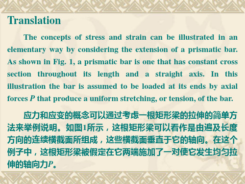
Eq.(1) can be regarded as the equation for the uniform stress in a prismatic bar. This equation shown that stress has units of force divided by area. When the bar is being stretched by the force P , as shown in the figure, the resulting stress is a tensile stress; if the forces are reversed in direction, causing the bar to be compressed, they are called compressive stress.
工程力学专业英语词组+解释

正应力 normal stress
切应力 shear stress
静水压力 hydrostatic pressure
集中力 concentrated force
分布力 distributed force
静定梁 statically determinate beam
静不定梁 statically indeterminate beam
相容方程 compatibility equation
补充方程 complementary equation
中性轴 neutral axis
圆截面 circular cross section
曲率半径的倒数 reciprocal of radius of curvature
纵轴 longitudinal axis
悬臂梁 cantilever beam
简支梁 simply supported beam
微分方程 differential equation
两端作用扭矩 twisted by couples at two ends
刚体 rigid body
扭转角 twist angle
静力等效 statically equivalent
相互垂直平面 mutually perpendicular planes
通过截面形心 through the centroid of the cross section
一端铰支 pin support at one end
一端固定 fixed at one end
弯矩图 bending moment diagram
工程力学双语课件ch06-ForceAnalysisofStructuresandMachines重点

27
6.6 Method of she point A:
研究A点: Again Y 0 由Y 0
Sb cos45o P 0
28
Sb 2P
6.6 Method of sections
① 研究整体求支反力 解:
X 0 XA 0 MB 0
YA P
Y 3a P 2a P a 0
21
6.6 Method of sections
② Draw a cut I-I, study the leftA'
hand section of the truss.
24
6.6 Method of sections
3. The judgments of the internal forces of special elements 三、特殊杆件的内力判断 ① If no load acts on a two-element joint and the two elements are not collinear, the internal forces of them are zero, they are called zero elements. 两杆节点无载荷、且两杆不在 S1 S2 0 一条直线上时,该两杆是零杆。 ② If no load acts on a three-element joint and two elements of them are collinear, the third is a zero element. 三杆节点无载荷、其中两杆在一条 直线上,另一杆必为零杆 S S
工程力学英文版课件04 Equilibrium of a Rigid Body

? Study Table 4-1
? Internal forces are never shown on the free-body diagram, since they occur in equal but opposite collinear pairs and therefore cancel out.
? If a support prevents translation of a body in a particular direction, then thethat direction.
? If rotation is prevented, then the support exerts a couple moment on the body.
6
IMPORTANT POINTS ? No equilibrium problem should be solved without first drawing
the free-body diagram, so as to account for all the forces and couple moments that act on the body.
Identify each loading and give dimensions. The forces and couple moments that are known should be labelled with their proper magnitudes and directions. Letters are used to represent the magnitudes and direction angles of unknown forces and couple moments. Establish an x, y coordinate system so that these unknowns can be identified.
工程力学英文版课件02 Equilibrium of Concurrent Forces
N1 G G
N2
7
II. Some reactive forces 1. Rope, chain and driving belt Only tension can be applied on them, so the reactive forces act along the rope at the contact point directing away from the body.
18
Two-Force Member: forces are applied at only two points on a member, the member is called a 19 two-force member.
[Example] Draw the free-body diagram of all components shown in figure.
§3–4 Equilibrium by Rectangular
Component Method
2
§3-1 Construction of a Free-body Diagram
1. Conditions for Equilibrium A body under the concurrent forces system in a plane is in a state of equilibrium if the resultant force on it are zero.
Mathematical r 2 (r h) 2 Method: tg 0.577 r h
F Ptg
NB
cos
27
§3-3 Four or More Forces in Equilibrium
工程力学英文版课件06 Forces in Space
A force in space
is a vector that has
three rectangular
g
components. A
b
O
q
Fxy
right-hand coordinate system will be used.
3
The three rectangular components of a force
specific weight of the body, measured as a weight
per unit volume, then
dP g dV
and therefore
xC
xg dV g dV
yC
yg dV g dV
zC
zg dV g dV
(2) (2)
30
Center of Mass
1
Forces in Space
§7–1 Components of a Force in Space §7–2 Resultant of Concurrent forces in Space §7–3 Equilibrium of a Concurrent Force System §7–4 Support Conditions for Bodies in Space §7–5 Equilibrium of a Rigid Body in Space §7–6 Center of Gravity and Centroid for a Body
2
§7-1 Components of a Force in Space
In previous chapters coplanar force systems
- 1、下载文档前请自行甄别文档内容的完整性,平台不提供额外的编辑、内容补充、找答案等附加服务。
- 2、"仅部分预览"的文档,不可在线预览部分如存在完整性等问题,可反馈申请退款(可完整预览的文档不适用该条件!)。
- 3、如文档侵犯您的权益,请联系客服反馈,我们会尽快为您处理(人工客服工作时间:9:00-18:30)。
Equilibrium of a three-force body A body acted on by three forces is called a three-force body.
If a body is subjected to only three forces, then it is necessary that the forces be either concurrent or parallel for the body to be in equilibrium.
3
2. Construction of free-body diagrams Successful application of the equation of equilibrium requires a
complete specification of all the known and unknown external forces that act on the body. It is necessary to show all the forces and couple moments that the surroundings exert on the body so that these effects can be accounted for when the equations of equilibrium are applied. For this reason, a thorough understanding of how to draw a free-body diagram is of primary importance for solving problems in mechanics.
11
§5-3 Equilibrium of a Rigid Body
Equilibrium of a two-force body When a body is subjected to no couple moments and forces
are applied at only two points on a body, the body is called a twoforce body. For equilibrium of a two-force body the force acting at one point must be equal in magnitude, opposite in direction, and have the same line of action as the force acting at the other point.
7
• Study Table 4-1
• Internal forces are never shown on the free-body diagram, since they occur in equal but opposite collinear pairs and therefore cancel out.
8
§5-2 Equations of Equilibrium
Equations for equilibrium of a rigid body When a body is subjected to a system of forces, which all lie in
the x-y plane, then the forces can be resolved into their x and y components. Consequently, the conditions for equilibrium in two dimensions are:
4
Procedure for drawing a free-body diagram To construct a free-body diagram for a rigid body or group of
bodies considered as a single system, the following steps should be performed: Draw outlined shape. Imagine the body to be isolated or cut ‘free’ from its constraints and connections and draw its outlined shape. Show all forces and couple moments. Identify all the external forces and couple moments that act on the body. Those generally encountered are due to
Fx Fy
0 0
M A 0
(1)
9
Alternative sets of equilibrium equations Although equations (1) are most often used for solving coplanar
equilibrium problems, two alternative sets of three independent equilibrium equations may also be used. One such set is:
• The weight of a body is an external force, and its effect is shown as a single resultant force acting through the body’s centre of gravity G.
• Couple moment can be placed anywhere on the free-body diagram, since they are free vectors. Forces can act at any point along their lines of action, since they are sliding vectors.
6
IMPORTANT POINTS • No equilibrium problem should be solved without first drawing
the free-body diagram, so as to account for all the forces and couple moments that act on the body.
13
[Example 1] A crane as shown in figure, P=700kN, W=200kN (The maximum lifting weight). Determine (a) The range of the weight of the balance member Q. (b) when Q=180kN, the reactive forces at 0 0
(3)
M C 0
Here it is necessary that points A, B and C do not lie on the same
line.
Any one of the three sets of equations may be used to solve an equilibrium problem. The problem can be simplified if we select equations that result in only one unknown in each equation. Only three of the equations can be independent.
• If a support prevents translation of a body in a particular direction, then the support exerts a force on the body in that direction.
• If rotation is prevented, then the support exerts a couple moment on the body.
1
Equilibrium of a Rigid Body
§5–1 Introduction §5–2 Equations of Equilibrium §5–3 Equilibrium of a Rigid Body §5–4 Statical Determinacy and Constraint
5
(1) Applied loadings, (2) reactions occurring at the supports or at points of contact with other bodies (see Table 4-1, 4-2), and (3) the weight of the body.
Many mechanical elements act as two- or three-force body, and the ability to recognize them in a problem will considerably simplify an equilibrium analysis.
MFaA
0 0
(2)
M B 0
When using these equations, it is required that a line passing
through points A and B is not perpendicular to the a axis.
10
A second alternative set of equations is: