Wire-Bonding工艺介绍和Gold-Wire特性
Wire_bonding铝丝超声焊技术科普知识

Wire bonding铝丝超声焊技术科普知识一、什么是Wire bonding铝丝超声焊技术?铝丝超声焊是其实是使用铝作为金属丝的一种wire bonding技术。
而Wire bonding是一种初级内部互连方法,用作连到实际的裸片表面或器件逻辑电路的最初一级的内部互连方式,这种连接方式把逻辑信号或芯片的电讯号与外界连起来。
Wire bonding有两种形式:球焊和楔焊。
金丝球焊是最常用的方法,在这种制程中,一个熔化的金球黏在一段在线,压下后作为第一个焊点,然后从第一个焊点抽出弯曲的线再以新月形状将线(第二个楔形焊点)连上,然后又形成另一个新球用于下一个的第一个球焊点。
金丝球焊被归为热声制程,也就是说焊点是在热(一般为150)、超声波、压力以及时间的综合作用下形成的。
第二种压焊方法是楔形制程,这种制程主要使用铝线,但也可用金线,通常都在室温下进行。
楔焊将两个楔形焊点压下形成连接,在这种制程中没有球形成。
铝线焊接制程被归为超声波线焊,形成焊点只用到超声波能、压力以及时间等参数。
不同制程类型的采用取决于具体的应用场合。
比如金线压焊用于大批量生产的场合,因为这种制程速度较快。
铝线压焊则用于封装或PCB不能加热的场合。
另外,楔形压焊制程比金线压焊具有更精细的间距。
目前,金线压焊的间距极限为60μm;采用细铝线楔形压焊可以达到小于60μm的间距。
在此技术中所用金属线,即Bonding Wire是半导体器件和集成电路组装时,为使芯片内电路的输入/输出连接点与引线框架的内接触点之间实现电气连接的内引线。
Bonding Wire作为连接内引线,应具有电导率高,导电能力强,与导体材料的结合力强,化学性能稳定等性能优点。
Bonding Wire的直径,通常在25到75μm之间。
市场上主要有四种材料用作Bonding Wire,分别为金、银、铜和铝。
二、 Wire Bonding技术在电动汽车动力电池领域的应用Wire bonding自从1970年起一直广泛应用于微电子和电力电子领域。
wire bonding 介绍
DEFECT
封裝簡介
晶片Die
金線 Gold Wire 導線架
Lead fram
封裝流程
Wafer Grinding
ห้องสมุดไป่ตู้
Wafer Saw
Die Bonding
toaster
Wire Bonding
Die Surface Coating
Molding
Laser Mark
BGA
Solder Ball Placement
Eagle
MACHINE SPECIFICATIONS (II) •Vision System •Pattern Recognition Time 70 ms / point •Pattern Recognition Accuracy + 0.37 um •Lead Locator Detection 12 ms / lead (3 leads/frame) •Lead Locator Accuracy + 2.4 um •Post Bond Inspection First Bond, Second Bond Wire Tracing •Max. Die Level Different 400 – 500 um
lead
Capillary rises to loop height position
pad
lead
Capillary rises to loop height position
pad
lead
Capillary rises to loop height position
pad
lead
Capillary rises to loop height position
Wire-Bonding工艺以及基本知识 PPT

Capillary的選用:
Hole径(H)
Hole径是由规定的Wire径WD(Wire Diameter)
来決定
H
H=1.2~1.5WD
WD
Capillary主要的尺寸:
H:Hole Diameter (Hole径) T:Tip Diameter B:Chamfer Diameter(orCD) IC:Inside Chamfer IC ANGLE:Inside Chamfer Angle FA:Face Angle (Face角) OR:Outside Radius
Die 第一焊点搜索速度1st Search Speed 1
3. 第一焊點接触階段
最初的球形影响参数: 接觸压力和预备功率 Impact Force and Standby Power
1/16 inch 總長L
Capillary尺寸對焊線品質的影響:
1. Chamfer径(CD) Chamfer径过于大的话、Bonding強度越弱,易造成虛焊.
CD
CD
大家应该也有点累了,稍作休息
大家有疑问的,可以询问和交流
2. Chamfer角(ICA ) Chamfer角:小→Ball Size:小 Chamfer角:大→Ball Size:大
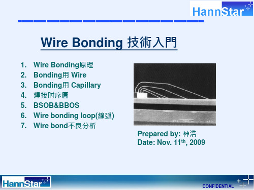
1.Wire Bonding原理
IC封裝中電路連接的三種方式: a. 倒裝焊(Flip chip bonding) b. 載帶自動焊(TAB---tape automated bonding) c. 引線鍵合(wire bonding)
Wire Bonding------引線鍵合技術
Wire Bonding的作用
Wire Bonding的四要素: ➢ Time(時間) ➢ Power(功率) ➢ Force(壓力) ➢ Temperature(溫度)
引线键合(WireBonding)

引线键合(WireBonding)引线键合(Wire Bonding)——将芯片装配到PCB上的方法 | SK hynix Newsroom结束前工序的每一个晶圆上,都连接着500~1200个芯片(也可称作Die)。
为了将这些芯片用于所需之处,需要将晶圆切割(Dicing)成单独的芯片后,再与外部进行连接、通电。
此时,连接电线(电信号的传输路径)的方法被称为引线键合(Wire Bonding)。
其实,使用金属引线连接电路的方法已是非常传统的方法了,现在已经越来越少用了。
近来,加装芯片键合(Flip Chip Bonding)和硅穿孔(Through Silicon Via,简称TSV)正在成为新的主流。
加装芯片键合也被称作凸点键合(Bump Bonding),是利用锡球(Solder Ball)小凸点进行键合的方法。
硅穿孔则是一种更先进的方法。
为了了解键合的最基本概念,在本文中,我们将着重探讨引线键合,这一传统的方法。
一、键合法的发展历程图1. 键合法的发展史:引线键合(Wire Bonding)→加装芯片键合(Flip Chip Bonding)→硅穿孔(TSV)下载图片为使半导体芯片在各个领域正常运作,必须从外部提供偏压(Bias voltage)和输入。
因此,需要将金属引线和芯片焊盘连接起来。
早期,人们通过焊接的方法把金属引线连接到芯片焊盘上。
从1965年至今,这种连接方法从引线键合(Wire Bonding),到加装芯片键合(Flip Chip Bonding),再到TSV,经历了多种不同的发展方式。
引线键合顾名思义,是利用金属引线进行连接的方法;加装芯片键合则是利用凸点(bump)代替了金属引线,从而增加了引线连接的柔韧性;TSV作为一种全新的方法,通过数百个孔使上下芯片与印刷电路板(Printed Circuit Board,简称PCB)相连。
二、键合法的比较:引线键合(Wire Bonding)和加装芯片键合(Flip Chip Bonding)图2. 引线键合(Wire Bonding) VS加装芯片键合(Flip Chip Bonding)的工艺下载图片三、引线键合(Wire Bonding)是什么?图3. 引线键合的结构(载体为印刷电路板(PCB)时)下载图片引线键合是把金属引线连接到焊盘上的一种方法,即是把内外部的芯片连接起来的一种技术。
Wire Bond 工艺培训

1. Wire与DIE之间不能接触。 测量标准:大于两倍线径。 2. Wire与Lend之间不能接触。 测量标准:大于两倍线径。 3. Wire与Wire之间不能相交。 测量标准:大于两倍线径。 4. Wire与Gnd之间不能接触 (主要运用与QFN产品)
15
压焊线弧类型
➢ 普通弧
基础概念
压焊是做什么的?
压焊就是用金、铜等导线将粘在框架上的芯 片与框架管脚连通,即芯片可通过管脚与外部 电路形成通路,来发挥其功能。
1
基础概念
焊线原理:
在高温、超声波振动、压力等因素下,使金 与铝、金与银这两种相互接触的金属发生软化 变形,同时两种金属间发生原子扩散,形成金 属化合物,即合金,达到焊接效果。
2
劈刀
3
劈刀
劈刀分为普通劈刀(左)和柱状劈刀(右) 劈刀的材料分为陶瓷、人造宝石等
4
劈刀
柱状劈刀(密间距劈刀)
5
案例分析
Capillaries头部沾污引起的Ball Size 球形不良
Wire Bond加工过程中劈刀打到异物, Power未将异常清理掉,导致残留 在劈刀头部。
导致Ball size 出现球形不良球变形 现象。
32
压焊的异常案例
Ball Size 功率圈比对:
Ball Size完整无异常
Ball Size不完整有异常
球形功率圈良好无异常 Wire Pell后无Peelling现象 Wire Pell后无脱球现象 Ball Size两边距离Pad 6um Ball Size Z距离在范围内
球形异常/无功率圈 Wire Pell后出现Peelling现象 Wire Pell后有脱球现象 Ball Size两边距离Pad 6um Ball Size Z距离超过范围
wire bonding 详细学习资料 ppt课件
wire bonding 详细学 ASSEMBLY F习LO资W料OF PLASTIC IC
Wire Bond 原理 M/C Introduction Wire Bond Process Material SPEC Calculator DEFECT
wire bonding 详细学 习资料
• Low impact force •Real time Bonding Force monitoring • High resolution z-axis position with 2.5 micron per step resolution • Fast contact detection • Suppressed Force vibration • Fast Force response • Fast response voice coil wire clamp
(3 leads/frame) •Lead Locator Accuracy + 2.4 um •Post Bond Inspection First Bond, Second Bond
Wire Tracing •Max. Die Level Different 400 – 500 um
•Facilities •Voltage 110 VAC (optional 100/120/200/210/ •220/230/240 VAC
wire bonding 详细学 习资料
•Linear 3 phase AC Servo motor •High power AC Current Amplifier •DSP based control platform •High X-Y positioning accuracy of +/- 1 mm •Resolution of 0.2 mm
wire_bonding__介绍

lead
Capillary rises to loop height position
pad
lead
Capillary rises to loop height position
pad
lead
Capillary rises to loop height position
pad
lead
Capillary rises to loop height position
Eagle
MACHINE SPECIFICATIONS (II) •Vision System •Pattern Recognition Time 70 ms / point •Pattern Recognition Accuracy + 0.37 um •Lead Locator Detection 12 ms / lead (3 leads/frame) •Lead Locator Accuracy + 2.4 um •Post Bond Inspection First Bond, Second Bond Wire Tracing •Max. Die Level Different 400 – 500 um
WIRE BOND PROCESS INTRODUCTION
CONTENTS
ASSEMBLY FLOW OF PLASTIC IC Wire Bond 原理 M/C Introduction Wire Bond Process Material SPEC Calculator
SEARCH SPEED1
pad
SEARCH TOL 1
lead
Free air ball is captured in the chamfer
Wire-Bonding工艺以及基本知识参考幻灯片
Smaller CD – Smaller
MBD
Bigger CD – Bigger
MBD
CD MBD
CA:70(Degree
)
CD MBD
CA:120(Degre
e)
将Chamfer角由90°变更為120°可使Ball形状变大,随之 Ball的宽度变宽、与Pad接合面積也能变宽。
Chamfer Angle:90°
Chamfer Angle:120°
CONFIDENTIAL
3. OR(Outer Radius)及FA(Face Angle): 对Hill Crack、Capillary的OR(Outer Radius)及FA(Face Angle)的數值是重要影響因素
2nd Neck部 Crack発生ห้องสมุดไป่ตู้
荷重过度附加接触面导致破损 Crack発生
1/16 inch 總長L
CONFIDENTIAL
Capillary尺寸對焊線品質的影響:
1. Chamfer径(CD) Chamfer径过于大的话、Bonding強度越弱,易造成虛焊.
CD
CD
CONFIDENTIAL
2. Chamfer角(ICA ) Chamfer角:小→Ball Size:小 Chamfer角:大→Ball Size:大
CONFIDENTIAL
3.Bonding用 Capillary
Capillary的選用:
Hole径(H)
Hole径是由规定的Wire径WD(Wire Diameter)
来決定
H
H=1.2~1.5WD
WD
Capillary主要的尺寸:
H:Hole Diameter (Hole径) T:Tip Diameter B:Chamfer Diameter(orCD) IC:Inside Chamfer IC ANGLE:Inside Chamfer Angle FA:Face Angle (Face角) OR:Outside Radius
Wire Bond 工艺培训
金线
8
金线
线径(μm) 18 20 23 25 38 50
供应商
贺利氏 励福 贺利氏 励福 励福 贺利氏 励福 康强
含金量
99.90% /
99.99% / /
99.99% /
99.99%
型号
HA10 KL1 HA6 KM1 KM1 HD3 KM1 KG3
B/L(gf)
>5 >6 >6 >7 >9 >9 >21 >32
打线方式管脚到管脚连线打线方式反向打线方式先在需要焊线个金球再在金球上打上鱼尾打线方式多个焊点之间相互短接主要方法是在焊点之间使用植球进行短接要求焊点之间间距小于10um
基础概念
压焊是做什么的?
压焊就是用金、铜等导线将粘在框架上的芯 片与框架管脚连通,即芯片可通过管脚与外部 电路形成通路,来发挥其功能。
为最简单的弧形,通常用于 焊点在芯片边缘的产品连线。
➢ 平弧(平台弧、工作弧)
通常用于有跨芯片的线弧或比 较长的线弧,后面拐角可根据 需要调整高低。
16
压焊线弧类型
➢ Bga类线弧
常用于长线弧(2mm以上金 线),线弧中间有2-4个拐角。
17
压焊线弧类型
➢ M弧
可以调出较低线弧,目前用来作 0.5mm胶体厚度QFN\DFN、 TO系列产品
1
基础概念
焊线原理:
在高温、超声波振动、压力等因素下,使金 与铝、金与银这两种相互接触的金属发生软化 变形,同时两种金属间发生原子扩散,形成金 属化合物,即合金,达到焊接效果。
2
劈刀
3
劈刀
劈刀分为普通劈刀(左)和柱状劈刀(右) 劈刀的材料分为陶瓷、人造宝石等
4
劈刀
柱状劈刀(密间距劈刀)
Wire-Bonding工艺以及基本知识

A. 15(15XX):直徑1/16 inch (約1.6mm),標準氧化鋁陶瓷 B. XX51:capillary產品系列號 C. 18: Hole Size 直徑為0.0018 in.(約46μm ) D. 437:capillary 總長0.437 in.(約11.1mm) E. GM: capillary tip無拋光; (P: capillary tip有拋光) F. 50: capillary tip 直徑T值為0.0050 in. (約127μm) G. 4: IC為0.0004 in. (約10μm) H. 8D:端面角度face angle為 8° I. 10:外端半徑OR為0.0010 in.(約25μm) J. 20D:錐度角為20° K. CZ1:材質分類,分CZ1,CZ3,CZ8三種系列
1.Wire Bonding原理
IC封裝中電路連接的三種方式: a. 倒裝焊(Flip chip bonding) b. 載帶自動焊(TAB---tape automated bonding) c. 引線鍵合(wire bonding)
Wire Bonding------引線鍵合技術
Wire Bonding的作用
线夹 打开– Wire Clamp Open
在第一焊点搜索高度开始, 焊头使用固定的 速度搜索接触高度 At Search Height Position Bond Head Switch to Constant Speed(Search Speed) to Search For Contact
第一焊点搜索高度1st Search Height
Smaller CD – Smaller
MBD
Bigger CD – Bigger
MBD
Wire-Bonding工艺以及基本知识 PPT课件

CONFIDENTIAL
3. OR(Outer Radius)及FA(Face Angle): 对Hill Crack、Capillary的OR(Outer Radius)及FA(Face Angle)的數值是重要影響因素
2nd Neck部 Crack発生
荷重过度附加接触面导致破损 Crack発生
BSOB 時BOND HEAD的動作步驟:
CONFIDENTIAL
BSOB的二個重要參數:
1. Ball Offset:此項設定值球時,當loop base 拉起後,capillary 要向何方向拉弧 設定範圍: -8020, 一般設定: -60
設定值為正值 : 代表capillary 向lead 的方向拉弧 設定值為負值 : 代表capillary 向die 的方向拉弧
Die 第一焊点搜索速度1st Search Speed 1
CONFIDENTIAL
3. 第一焊點接触階段
最初的球形影响参数: 接觸压力和预备功率 Impact Force and Standby Power
线夹打开- Wire Clamp Open
最初的球形和质量決定于1ST BOND : CONTACT TIME CONTACT POWER, CONTACT FORCE,
Smaller CD – Smaller
MBD
Bigger CD – Bigger
MBD
CD MBD
CA:70(Degree
)
CD MBD
CA:120(Degre
e)
将Chamfer角由90°变更為120°可使Ball形状变大,随之 Ball的宽度变宽、与Pad接合面積也能变宽。
wirebonding封装工艺

wirebonding封装工艺
Wirebonding封装工艺是一种把金属线接到封装器件表面的加工办法。
Wirebonding封装工艺可以广泛应用于电子封装和IC封装行业,特别是
当焊接办法无法实现时,Wirebonding封装技术可以发挥作用。
Wirebonding封装工艺主要步骤有三:前处理、Wirebonding和清洁处理。
前处理过程主要是对封装表面形态和电化学性能进行处理,以保证Wirebonding和表面清洁处理工艺正常进行;Wirebonding过程包括定位、钢丝熔合、焊接和压印,Wirebonding正确及有效地完成了金属线被熔接
到电子封装器件表面的过程;清洁处理过程是对已完成处理的封装器件进
行清洁处理,以确保最终产品的清洁度和完好度。
wire_bonding__介绍
WIRE BONDWIRE BOND PROCESS INTRODUCTIONCONTENTSÂASSEMBLY FLOW OF PLASTIC IC ÂWire Bond 原理M/C IntroductionÂM/C IntroductionÂWire Bond ProcessWire Bond ProcessÂMaterialÂSPECÂCalculatorÂDEFECTG ld Wi晶片Die金線Gold Wire導線架Lead framWafer Grinding Die Bonding Wafer Saw toaster Wire Bonding Die SurfaceCoating Molding Laser MarkSolder BallPlacement SingulationBGA PackingDejunk TRIM SolderPlatingDejunk TRIM SURFACE MOUNTPKG Solder Plating TRIM/FORMING THROUGH HOLE PKGWire Bond 原理Ball Bond Wedge Bond (2d B d)( 1st Bond )( 2nd Bond )Gold wirepadleadB.PRINCIPLEPRESSUREVIBRATION AL2O3MOISTURECONTAMINATIONGOLD BALLGLASSAlSiO2Si銲接條件ÂHARD WELDINGÂPressure (Force)A lif&FÂAmplify & FrequecyÂWelding Time (Bond Time) Welding Time(Bond Time)e d g e patu e(eate)ÂWelding Tempature (Heater)ÂTHERMAL BONINGÂThermal CompressureÂUltrasonic Energy (Power)Bond Head ASSY•Low impact force•Real time Bonding Force monitoringReal time Bonding Force monitoring•High resolution z-axis position with 2.5 micron per step resolutionstep resolution•Fast contact detection•Suppressed Force vibrationSuppressed Force vibration•Fast Force responseF t i il i l•Fast response voice coil wire clampX Y Table•Linear 3 phase AC Servo motorHigh power AC Current Amplifier•High power AC Current Amplifier•DSP based control platform•High X-Y positioning accuracy of +/-1 mm Hi h X Y iti i f/1•Resolution of 0.2 mmW/H ASSY •changeover•· Fully programmable indexer & tracks·Fully programmable indexer&tracks•· Motorized window clamp with soft close feature•· Output indexer with leadframe jam protection feature•Tool less conversion window clamps and top plate enables fast device•Bonding SystemB di M th d Th i (TS)MACHINE SPECIFICATIONS (I)•Bonding Method ÎThermosonic (TS)•BQM Mode ÎConstant Current, Voltage, Power and Normal(Programmable)•Loop Type ÎNormal, Low, Square & J •XY Resolution Î0.2 um•Z Resolution (capillary travelling motion)Î2.5 um •Fine Pitch Capability Î35 mm pitch @ 0.6 mil wire N f B di Wi t 1000•No. of Bonding Wires Îup to 1000•Program Storage Î1000 programs on Hard Disk •Multimode Transducer System •Multimode Transducer SystemÎProgrammable profile, control and vibration modes•Vision System MACHINE SPECIFICATIONS (II)y•Pattern Recognition Time Î70 ms / point •Pattern Recognition Accuracy Î+ 0.37 um •Lead Locator Detection Î12 ms / lead(3 leads/frame)•Lead Locator Accuracy +24um•Lead Locator Accuracy Î+ 2.4 um •Post Bond Inspection ÎFirst Bond, Second BondWire Tracing g•Max. Die Level Different Î400 –500 um •Facilities•Voltage 110 VAC (optional 100/120/200/210/•220/230/240 VAC•Material Handling System MACHINE SPECIFICATIONS (III)g y•Indexing Speed Î200 –250 ms @ 0.5 “ pitch •Indexer Resolution Î1um•Leadframe Position Accuracy +2milLeadframe Position Accuracy Î 2 mil •Applicable Leadframe ÎW = 17 –75 mm @ bonding area in Y = 65mm= 17 –90 mm @ bonding area in Y = 54mmL =280mm [Maximum]L = 280 mm [Maximum]T = 0.075 –0.8 mmApplicable Magazine W =100mm (Maximum)•Applicable Magazine ÎW = 100 mm (Maximum)L = 140 –300 mmH = 180 mm (Maximum)M i Pi h 2410(009”039“)•Magazine Pitch Î 2.4 –10 mm (0.09” –0.39 “)•Device Changeover Î< 4 minutes•Package Changeover Î< 5 minutes•Number of Buffer Magazine Î3 (max. 435 mm)Bonding ProcessgThe Wire BondTempPREHEAT BONDSITE10 200+/--10 CU L/F200+/--10 200+/CU L/F200+/10 230+/--10 AL L/F210+/--10 230+/AL L/F210+/BGA 150+/--10 160+/10 160+/--10 BGA 150+/10 160+/--10 TFBGA150+/--10 160+/ TFBGA150+/10160+/ LBGA 150+/--10 160+/10 160+/--10 LBGA 150+/150+/10160+/-LBGA150+/-160+/ NOT INCLUDE DEDICATE LINEi th h fin the chamferppadleadin the chamferi th h fSEARCH HEIGHTpadleadi th h f in the chamferpad SEARCH SPEED1 SEARCH TOL1pleadSEARCH TOL 1in the chamfer in the chamferpad SEARCH SPEED1 SEARCH TOL1pleadSEARCH TOL 1in the chamferin the chamferSEARCH SPEED1SEARCH TOL 1SEARCH TOL1pad leadin the chamferin the chamferSEARCH SPEED1SEARCH TOL 1SEARCH TOL1pad leadin the chamferin the chamferSEARCH SPEED1SEARCH TOL 1SEARCH TOL1pad leadSEARCH SPEED1SEARCH TOL 1SEARCH TOL1pad leadIMPACT FORCESEARCH SPEED1SEARCH TOL 1SEARCH TOL1pad leadContactContactPRESSUREUltraSonicVibrationheatpad leadBaseBasePRESSUREUltraSonicVibrationheatpad leadheight positionheight positionpad leadheight positionheight positionpad leadheight positionheight positionpad leadheight positionheight positionpad leadheight positionheight positionpad leadheight positionheight positionRHpad leadRD (Reverse Distance)()pad leadpad leadpad leadWIRE CLAMPCLOSE‘CLOSE’CalculatedWire Lengthpad leadCalculatedWire Lengthpad leadSEARCHDELAYpad leadTRAJECTORY pad leadTRAJECTORY pad leadTRAJECTORY pad leadTRAJECTORY pad leadTRAJECTORY pad leadTRAJECTORY pad leadTRAJECTORY pad leadTRAJECTORY pad leadTRAJECTORY pad leadTRAJECTORY pad lead2nd Search Height 2nd Search Height Search Speed 2pad leadSearch Speed 2Search Tol 2Search Speed 2pad lead Search Speed 2Search Tol 2。
- 1、下载文档前请自行甄别文档内容的完整性,平台不提供额外的编辑、内容补充、找答案等附加服务。
- 2、"仅部分预览"的文档,不可在线预览部分如存在完整性等问题,可反馈申请退款(可完整预览的文档不适用该条件!)。
- 3、如文档侵犯您的权益,请联系客服反馈,我们会尽快为您处理(人工客服工作时间:9:00-18:30)。
金线焊接工具---劈刀
劈刀决定的一些参数: 1、Bond Pad Pitch
金线焊接工具---劈刀
T--Tip Diameter, BTNK—Bottleneck Height&Angle, CA—Cone Angle Will affect bond pad pitch.
2、1st Bond Diameter
Not move
affect Not affect
Go up with capillary
Form ball when 6000v on it
Not affect Not affect
金线球形焊接工艺介绍
Stage1
Stage2
Stage3
Stage4
Stage5
Stage6
Stage7
Stage8
H—Hole Diameter, ICA—Inner Chamfer Angle CD—Chamfer Diameter Will affect 1st bond diameter
金线焊接工具---劈刀
3、Wire Diameter
H—Hole Diameter
Hole diameter is usually 1.5X wire diameter
wire
Ultrasonic and force
Form ball when 6000v on it
Not affect
Go up to chamfer, affect touch die surface
Not move
Not affect
Form loop shape Not affect
Squashed and form 2nd bond
金线球形焊接工艺介绍
参数设置(power,force,time); 3、污染
材料本身的污染; 操作不当引起的污染;
其他焊接工艺介绍
1、铝线楔形焊接工艺 用于2mil及4~20mil铝线焊接;
2、金线条带焊接工艺 更好的电性能;
3、铜连接 更好的机械和热性能,低消耗;
金线焊接工具---劈刀
劈刀的结构(参数):
FA -- Face Angle OR -- Outer radius H -- Hole Diameter CD -- Chamfer Diameter T -- Tip Diameter
ICA -- Inner Chamfer Angle OD -- Outer diameter CA -- Cone Angle L -- Length BTNKH -- Bottleneck Height BTNKA -- Bottleneck Height
为5N(99。999%)黄金。 金线有两种: Doping和Alloy. Doping金线比5N Au有更好的机械性能。 Alloyed金线有更好的强度,但会损失一定
的电性能。
金线特性和选择
金线的几个特征参数: 1、breaking load
金线特性和选择
金线的几个特征参数: 2、neck strength 3、HAZ(heat affect zone)length
金线球形焊接工艺介绍
金线球形焊接工艺介绍
焊接质量的检测: 1、wire pull strength 2、ball shear strength 3、wire peel 4、crater test(etching)
金线球形焊接工艺介绍
影响焊接质量的因素: 1、材料
金线成分不同,要求的工艺参数也不同; 芯片加工工艺对焊接质量有直接影响; Leadframe/substratede材料和镀层; 2、机器的设置 capillary的安装; heatblock的安装和调整;
4、Looping
CA--Chamfer Angle, BTNK—Bottleneck Height&Angle
5、2 nd bond quality
T– Tip Diameter, FA—Face Angle, OR– Outer Radius
金线特性和选择
金线材质: 金线基材为4N(99。99%)黄金,经提纯
Gold Wire B、焊接表面
Die----Al Leadframe/substrate----Ag/Au
金线球形焊接工艺介绍
C、焊接温度 180℃~250℃
D、焊接能量 超声震动
它的工艺过程可以粗略分为四步: FAB→1st bond→looping→2nd bond
金线球形焊接工艺介绍
金线球形焊接工艺介绍
金线特性和选择
4、FAB(free air ball)hardness 5、current load rating;
金线特性和选择
ቤተ መጻሕፍቲ ባይዱ
金线特性和选择
6、resistivity (Ohm mm2/m)
金线特性和选择
选择金线的方法: Loop height Loop length Wire sweep Electrical performance Mechanical performance
5、2nd bond form
6、tail length create
7、 disconnect
Press the wire to lead Go up to a desired height Go up
8、new FAB stopped
open open close close open close close
金线球形焊接工艺介绍
stage 1、FAB
capillary stopped
Wire clamp
close
2、1st bond Go down to die surface, form
3、capillary rise
Go up to loop height
4、looping
Move from loop height point to 2nd bond
金线特性和选择
金线特性对封装工艺的影响
Breaking Load
HAZ length
low
Wire bigger sweep
Second better
bondability
high
lower
worse
short
Loop lower height
Loop height Stability in Low loop
bond pad
Smaller (better) higher
bigger
Pull lower strength
higher
better
long
higher
worse
金线特性和选择
金线特性对封装工艺的影响
FAB hardness
Neck strength
soft hard
low High
Ball diameter Bigger (Stability) (worse)
Shear lower strength
Damage to smaller
Wire Bonding工艺介绍和Gold Wire特性及选择
第一部分:Wire bonding工艺介绍 1、Wire bonding的几种形式
金线球形焊接; 铝线楔形焊接; 金线条带焊接; 铜连接;
金线球形焊接工艺介绍
金线球形焊接工艺是利用超声将芯片和导线 框架/基板用金线加以连接的工艺。 它的工艺条件: A、焊接材料