碳计算器使用说明书(CFC-101)
Model 450A-1数字口袋大气质碳 monoxide 测量器说明说明书
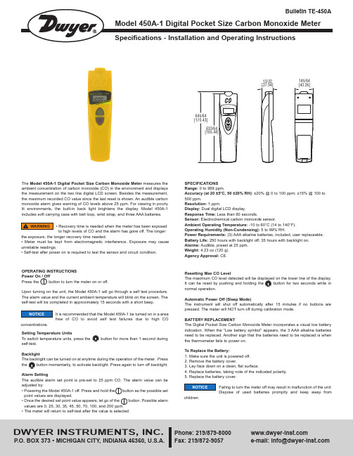
13/32145/64CALIBRATIONA periodic check of the system calibration is recommended.To enter calibration mode, turn off meter and press the and the button simultaneously for 2 seconds. For calibration, there are two options.0 ppm Calibration:Place meter in an area free of CO and enter calibration mode. The unit will calibrate automatically. The display will blink until calibration is complete. This takes about 10 minutes.100 ppm/500 ppm Calibration:After entering calibration mode, hold the button. 0,100, and 500 ppm will cycle through on the bottom of the display. Release the button when preferred calibration value is reached. Place meter in sealed box filled with the selected calibration gas standard for 15 minutes. Check if the reading meets calibration standard. If it does not, repeat the procedure.MAINTENANCEModel 450A-1is not field serviceable and should be returned if repair is needed (field repair should not be attempted and may void warranty). Be sure to include a brief description of the problem plus any relevant application notes. Contact customer service to receive a return goods authorization number before shipping.DWYER INSTRUMENTS, INC.Phone: 219/Fax: 219/872-9057e-mail:*******************©Copyright 2013 Dwyer Instruments, Inc.Printed in U.S.A. 8/13FR# R6-443742-00 Rev.2ppm 0-192535501002004008001600Symptoms and Applicable Standard Normal background levels.Maximum indoor air quality level; Maximum allowable concentration perASHRAE residential standards 62-1989 for living area.Maximum limit of 8 hours of continuous exposure per California OSHAworkplace standards.Maximum 8 hours of average exposure level per US OSHA workplacestandards.Maximum concentration for continuous exposure in any 8 hours averagelevel per OSHA standards.Remove employees from enclosed space if the CO concentrationexceeds 100 ppm per OSHA exposure limit.Mild headache, fatigue, nausea, and dizziness within 2-3 hours.Frontal headache, life threatening after 3 hours; Maximum concentrationin flue gases per the US EPA and AGA standards.Dizziness, nausea, convulsions, death within 2-3 hours.Nausea within 20 minutes, death within 2-3 hours.LEVELS AND EFFECT OF COProblemPower on but no displayDisplay disappears Calibration failureE 2E 3E 4E 31E 33E 35Solution• Verify that the time since power on has been over 300 mS.• Verify that the batteries are in good contact with the correct polarity.• Replace batteries with new batteries and try again.• Determine if the low battery indicator is on the screen before display disappears. If so, replace with new batteries.•Determine if the low battery indicator shows before calibration. If so,replace with new batteries and retry calibration.• Verify that the standard gas is correct.• The value is underflow.• The value is overflow.• The value is in error because of the original data.• A/D failure. Return meter for repair.• Measurement circuits failure. Return meter for repair.• Self-test failure• Turn the meter on again in area free of CO.• If error displays again, sensor failure. Return meter for repair.TROUBLESHOOTING。
碳计算器使用说明书(CFC-101)
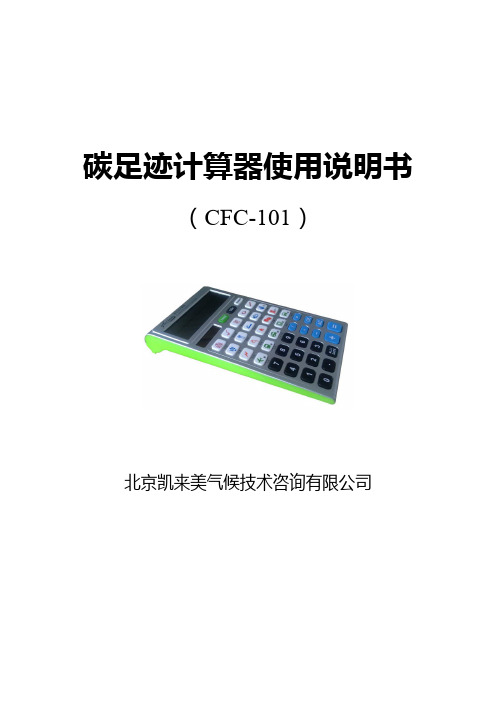
碳足迹计算器使用说明书(CFC-101)北京凯来美气候技术咨询有限公司计算器界面简介CFC-101碳足迹计算器使用说明书本计算器是一款革命性产品,专为低碳人士设计开发,在具备常规计算器功能的基础上,独创性地载入碳足迹计算功能,将人们在日常生活中“衣、食、住、行、用”各生活要素的消费数量换算成碳足迹数量,以判别其对环境的友好程度。
本计算器通俗易懂、简明扼要、老少咸宜,不仅是一款普及低碳知识,推动节能减排的科普工具,更是人们手边一款难得的多功能计算设备。
本计算器计算参数来源于科技部《全民节能减排手册》和国家发改委能源所。
本计算器具备碳足迹计算和常规办公计算两个模式,默认为常规办公计算模式,要进行碳足迹计算需通过“CO2”键切换。
在下面的章节中进行针对性介绍。
1.按键简介2.碳足迹计算模式您可以在按“ON/OFF”键开机进入常规计算模式后按“CO2”切换至碳足迹计算模式进行碳足迹计算。
●按相应功能键后“衣、食、住、行、用”中与其对应的图标和单位亮起,输入消费数量后按“=”键即可得出该消费数量对应的碳足迹值(得出的碳足迹值同时还会被记入内存里)。
●选择其他功能键进行相应的碳足迹计算(得出的碳足迹值同样也被累加进内存里)。
●计算完毕后按“ALL/DATE”键可以循环显示“衣、食、住、行、用”的碳足迹合计值、各自的小计值(显示在下行)及其所占合计值的比例(显示在上行)。
●按“TREE”键显示消除碳足迹所需植树棵数。
若需要进行新一轮碳足迹计算,可以按“AC”键使显示屏以及内存清零,或按“ON/OFF”键关开机后再按“CO2”键重新进入碳足迹计算模式。
计算实例:计算某人购买衣服5件、饮用白酒20Kg、用电1000度、驾驶小轿车5000Km以及使用一次性筷子200双所产生的碳足迹。
3.常规计算模式您可以在开机后直接进入常规计算模式进行常规计算。
3.1四则运算3.2记忆操作及利率和税率计算●M+:将显示屏上的数字与内存中的数字相加;●M-:将内存中的数字与显示屏上的数字相减;●MR:调用内存中的数据;●MC:清除内存中的数据;●MU:按下该键将进行利率和税率计算;关于"MU"的用法如下:3.3百分比计算4.注意事项请详细阅读以下使用注意事项,并将本说明书存放在易于取阅的位置以便日后随时查用。
Fluke 01A 电子数字燃料计说明书
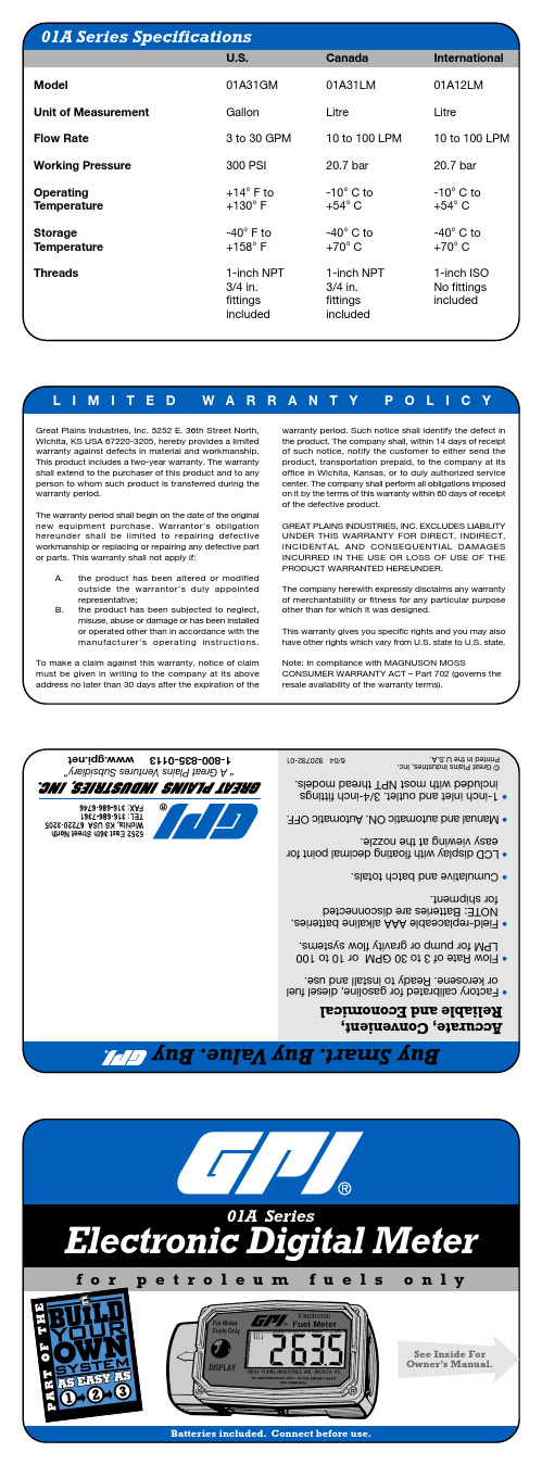
U.S.
Model
01A31GM
Unit of Measurement
Gallon
Flow Rate
3 to 30 GPM
Working Pressure
300 PSI
Operating Temperature
+14° F to +130° F
Storage Temperature
-40° F to +158° F
Threads
1-inch NPT 3/4 in. fittings included
Canada
01A31LM
Litre
10 to 100 LPM
20.7 bar
-10° C to +54° C
-40° C to +70° C
1-inch NPT 3/4 in. fittings included
4. Make sure the O-ring is fully seated and secure the faceplate with the four screws. The O-ring may need to be stretched to seat properly.
Calibration
The 01A Series meter is very sensitive to electric signals if operated within one to two inches of some electric motors.
Maintenance
Proper handling and care will extend the life and service of the meter.
用户手册_用于风机节能的计算器
FanSave 3.1 用户手册用于风机传动的节能计算器版本3.13AFE 64232681 REV C EN生效日: 04.03.2002Copyright © ABB Oy, Drives 20021 —概述FanSave是一款运行于Microsoft Excel (97版或以上)的计算工具,用以估计与其他风机控制系统相比,使用变速交流传动(变频器)带来的节能效果。
可在阻尼器控制、斜度控制、单速叶片控制与双速叶片控制方面进行比较。
计算是基于典型风机运行特点的。
因此,计算结果的准确度限定为±10%,其也受到输入数据准确度的影响。
结果只用于估计之目的。
本程序的结果不能用作保证节能的基础。
可打印计算结果。
3.1版中新增内容添加了使用美制的可能性。
添加了在北美市场提供的交流传动型号。
在推荐的传动型号列表中,添加了中压交流传动。
在3.1版中,使用“CO2排放量”,而不用“GHG排放量”。
3.0版中新增内容对用户接口进行了更新,用户不用滚屏就可以看到整个FanSave视图(适用于1024x768 像素或以上的桌面区域)。
可以评估由于能源消耗下降所带来的温室气体(GHG)排放减少量。
现在的投资准则也包括了净现值(NPV),所给出的收益指数用于投资项目排名。
2 —启动并运行程序所需软件运行能源计算工作簿时,需要使用Microsoft®Excel 97或以上版本。
使用FanSave工作簿之前,用户应对Microsoft Excel有一定的熟悉。
所提供的文件用于风机传动计算的FanSave文件合并到了Excel 工作簿FanSave31.xls之中。
安装可从光盘或软盘打开并运行计算工作簿,也可将文件拷贝到硬盘。
如果经常使用该程序,建议进行硬盘安装。
打开工作簿正常启动Excel。
进行风机计算时,打开FanSave31.xls。
要打开工作簿, 从位于屏幕顶部的菜单条上选定文件,然后从下拉菜单上选定打开。
2019-除碳器说明书-精选word文档 (9页)
本文部分内容来自网络整理,本司不为其真实性负责,如有异议或侵权请及时联系,本司将立即删除!== 本文为word格式,下载后可方便编辑和修改! ==除碳器说明书篇一:除二氧化碳器说明书除二氧化碳器Instruction for Decarbonator使用说明书Operation Instruction Manual无锡电站辅机厂Wuxi Power Auxiliary Equipment Works一、用途除二氧化碳器是用于驱除在水中的软化,除盐过程中,原水经过氢离子交换后,水中的重碳酸被破坏而产生的大量游离二氧化碳的设备,它设置于氢离子之后。
可以去除水中的二氧化碳,减少对设备的腐蚀,减轻阴离子交换的负荷,提高水处理设备系统的经济性与出水水质。
二、主要技术数据工作压力:常压工作温度:常温淋洒密度:60米3/米2时进水温度:15℃进水CO2含量:≤390毫克/升出水CO2含量:≤5毫克/升三、工作原理当含有H2CO3的水通过进水装置均匀地从容器顶部往下流过填料层时,水在填料的表面形成一种薄膜的流动,薄膜的流动造成了水中CO2和容器底部鼓进来的空气密切接触的条件,使水中气体与空气中气体容易自由交换,由于空气里的CO2含量很小,它的压力只占大气压力的0.003%左右,所以,水中的CO2就很容易扩散到空气里去,当水逐渐往下流动时,它所接触的却是比较新鲜的空气(因空气向上流动,越到容器上部,空气里吸收的CO2越多。
“新鲜”指空气中所吸收的CO2较少)更有利于CO2扩散出来,水流至底部时,水里的绝大部分CO2已被去除,残余的CO2含量在5毫克/升左右。
四、结构简述1. 进水装置:采用支管式结构,用硬聚氯乙稀管或不锈钢管制作。
2. 多孔板及填料:多孔板:小直径设备上采用硬聚氯乙稀板制作,大直径设备上采用钢板衬胶。
填料:采用Φ25×25×3陶瓷环或Φ50聚丙烯塑料空心多面球。
3. 进水管管径的选择按2米/秒流速考虑。
DYC1000定碳仪中文说明书
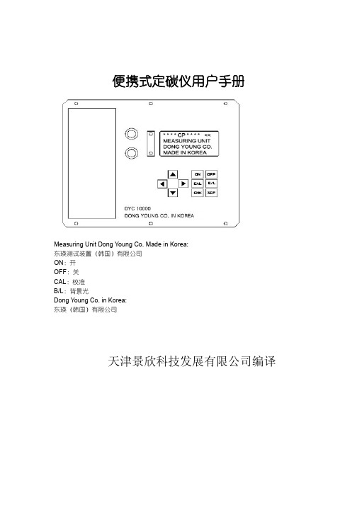
便携式定碳仪用户手册Measuring Unit Dong Young Co. Made in Korea:东瑛测试装置(韩国)有限公司ON:开OFF:关CAL:校准B/L:背景光Dong Young Co. in Korea:东瑛(韩国)有限公司天津景欣科技发展有限公司编译1.简介DYC-10000作为数字式手持校准氧探头测试仪器应用在热处理领域。
DYC-10000解决了模拟仪表测量偏差问题并使测量精度简单化。
2.特性1. 同时显示碳势测量值和室内温度2. 便于校准3. 自动完成常温补偿4. 自动显示,显示范围大于测试范围(包括大于或小于测试范围)。
5. 采用轻便的内置电池6. 电池(锂电池)待机时间长7. 随着电池电压的下降,设备自动关机3.安装3.1部件名称和功能CP:碳势TEMP:温度ON:开OFF:关CAL:校准B/L:背景光1. 用于试验线圈的连接端2. 温度传感器防护盖,确保室温测试3. 测试值和变换方向显示4. 电池状态显示5. 递增键6. 位移键(左移)7. 递减键8. 位移键(右移)9. 电源开启键10. 电源关闭键11. 背景灯开闭键12. 碳势测试状态切换键13. 碳势检测切换键14. 碳势校对状态切换键15. 试验线圈和适配器接收器3.2电源功能1)按住开启或关闭键,并持续一秒钟以上。
2)按下开启键,显示信息如图1所示。
3)本仪器可测试到适配器DC 12V电压,甚至包括充电电池的电压。
在右上角显示电池充电或放电状态。
(1) AC适配器的使用(将适配器插孔插到右下角的位置。
)锂电池充电和碳势测试可同步进行。
①如果电池正在充电,“CHG”字样在右上方闪烁。
②如果充电完成,“CHG”将不再显示。
(2) 内置电池的使用①电池三种状态,放电<<<,<<,<显示<<<充满电②电池状态的辨识<,通过适配器再次充电如果电源关闭,仍可以单独充电。
CS101说明书(V2 00)
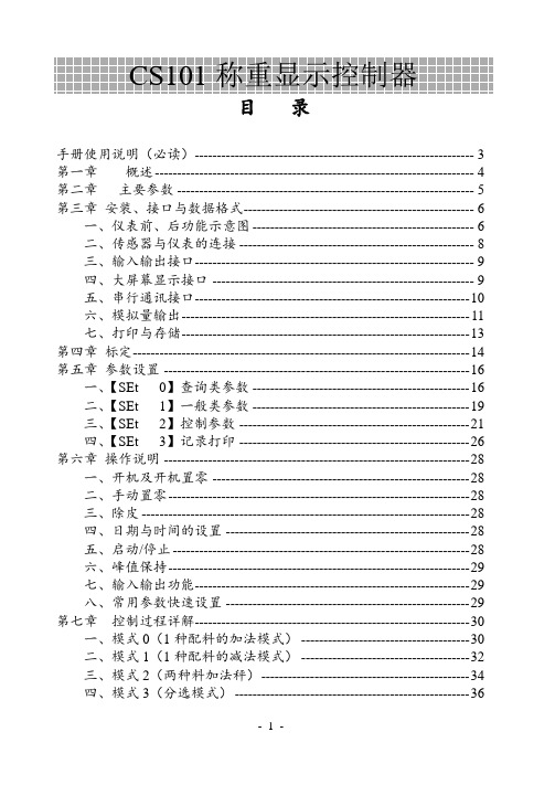
目录手册使用说明(必读)--------------------------------------------------------------- 3 第一章概述 ------------------------------------------------------------------------ 4 第二章主要参数 ------------------------------------------------------------------- 5 第三章安装、接口与数据格式---------------------------------------------------- 6一、仪表前、后功能示意图 -------------------------------------------------- 6二、传感器与仪表的连接 ----------------------------------------------------- 8三、输入输出接口--------------------------------------------------------------- 9四、大屏幕显示接口 ----------------------------------------------------------- 9五、串行通讯接口-------------------------------------------------------------- 10六、模拟量输出----------------------------------------------------------------- 11七、打印与存储----------------------------------------------------------------- 13 第四章标定---------------------------------------------------------------------------- 14 第五章参数设置 --------------------------------------------------------------------- 16一、【SEt 0】查询类参数 ------------------------------------------------- 16二、【SEt 1】一般类参数 ------------------------------------------------- 19三、【SEt 2】控制参数 ---------------------------------------------------- 21四、【SEt 3】记录打印 ---------------------------------------------------- 26 第六章操作说明 --------------------------------------------------------------------- 28一、开机及开机置零 ---------------------------------------------------------- 28二、手动置零-------------------------------------------------------------------- 28三、除皮 -------------------------------------------------------------------------- 28四、日期与时间的设置 ------------------------------------------------------- 28五、启动/停止 ------------------------------------------------------------------- 28六、峰值保持-------------------------------------------------------------------- 29七、输入输出功能-------------------------------------------------------------- 29八、常用参数快速设置 ------------------------------------------------------- 29 第七章控制过程详解-------------------------------------------------------------- 30一、模式0(1种配料的加法模式) -------------------------------------- 30二、模式1(1种配料的减法模式) -------------------------------------- 32三、模式2(两种料加法秤)----------------------------------------------- 34四、模式3(分选模式) ----------------------------------------------------- 36第八章维护保养及注意事项 ----------------------------------------------------41 附录一出错信息提示--------------------------------------------------------------43 附录二大屏幕数据波形图及格式------------------------------------------------44 附录三串行通信-指令应答方式的数据格式 --------------------------------45 附录四常见问题处理方法 ---------------------------------------------------------47亲爱的用户:在使用仪表前,敬请仔细阅读说明书!- 2 -手册使用说明(必读)为客户能正确使用仪表,用户必须了解本手册中相关内容。
活性炭油气回收系统用户使用手册
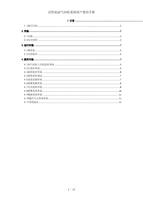
1.引言 .................................................................................................................1.1编写目的 (2)2.用途 (2)2.1功能 (2)2.2安全保密 (2)3.运行环境 (3)3.1硬设备 (3)3.2支持软件 (3)4.使用手册 (3)4.1油气回收上位机监控系统 (3)4.2主监控界面 (3)4.3流程监控界面 (6)4.4系统单机调试 (7)4.5设备监测界面 (7)4.6报警监测界面 (8)4.7历史趋势界面 (9)4.8报警查询界面 (10)4.9数据查询界面 (11)4.10操作日志查询界面 (11)4.11系统退出 (12)活性炭油气回收监控系统--用户使用手册1.引言1.1编写目的本文的目的就是能够让用户更清楚的了解油气回收上位机监控系统的使用流程,方便用户,让用户能够以最快的速度熟悉系统,快速上手。
2.用途2.1功能(1)系统登陆:根据不同的用户分配相应的权限对系统进行监测、管理。
方便了不同用户的管理及监测。
(2)流程监控界面:直观的监控了整个系统的工作流程。
在该界面可以随时的监测到系统中的每个泵、阀的启动及停止状态;温度、压力、液位及流速的时实数值。
(3)报警状态监测界面:监测了整个系统运行状态中的报警信息,包括各个阀的开、关报警;温度、压力、液位、流量的高范围及低范围的报警。
(4)设备状态监测界面:监测了整个系统运行状态中的各种报警信息,包括各个阀的开、关状态;温度、压力、液位、流量显示状态。
(5)历史趋势界面:可以根据您选择的时间段,查看各个阶段内整个系统中流量、温度、压力的变化趋势图。
(6)报警查询界面:可以根据时间查询所有发生过报警的历史记录。
(7)数据查询界面:可以根据时间来查询所有温度、压力、液位、等的历史记录。
CFC100-C使用说明
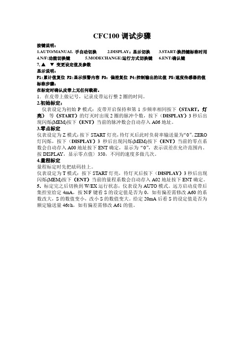
CFC100调试步骤按键说明:1.AUTO/MANUAL 手自动切换2.DISPLAY:显示切换3.START:换挡键标称时用4.N/F:功能切换键5.MODECHANGE:运行方式切换键6.ENT:确认键7.▲▼变更设定值及参数显示说明:F1:累计值复位 F2:显示报警内容 F3:偏差复位 F4:控制输出的比值 F5:速度传感器的值标称步骤:在标定时确认皮带上无任何载荷。
1.在皮带上做记号,记录皮带运行整2圈的时间。
2.初始标定:仪表设定为初始P模式:皮带开启保持和第1步频率相同按下(START,灯亮)等(START)的灯灭时出现2圈的脉冲个数,按下(DISPLAY)3秒后出现闪烁(MEM)按下(ENT)当前的脉冲数会自动存入A06地址。
3.零点标定仪表设定为Z模式:按下START灯亮,待灯灭后此时负荷率输送量为“0”。
ZERO 灯闪烁,按下(DISPLAY)3秒后出现闪烁(MEM)按下(ENT)当前的零点系数会自动存入A00地址按下ENT确定,显示为“0”,表示误差在允许范围内。
按DISPLAY,显示零点值〉350,不同的速度多做几次。
4.量程标定量程标定时先把砝码挂上。
仪表设定为T模式:按下START灯亮,待灯灭后按下(DISPLAY)3秒后出现闪烁(MEM)按下(ENT)当前的量程系数会自动存入A02地址按下ENT确定。
5.标定完之后切换到W/EX运行状态,仪表设为AUTO模式。
远方启动皮带后集控室给定4mA,按N/F键看S的设定值是否为0,如有偏差需修改A60的系数改大,S的数值变小,改小S的数值变大。
给定20mA后看S的设定值是否为额定输送量46t/h,如有偏差需修改A61的值。
电子皮带秤给煤机控制柜调试参数(CFC100-C)(5)变频器主要参数注意:运行方式设开关:1设为OFF,2设为ON变频器复位:P0010=30 P0970=1。
Itron CENTRON C1S 单相能耗计量器说明说明书

C1SCENTRON ® MeterThe CENTRON C1S solid-state meter is used for measuring single-phase energy consumption. With this solid-state meter, Itron presents a platform for residential metering with the flexibility to adapt as your needs expand and change.The CENTRON C1S is available as an energy meter with an LCD register. As an option, the meter is available with interchangeable personality modules,including demand, time-of-use (TOU), load profile and various communication options.FEATURES Flexible Platform»The CENTRON meter can easily be upgraded to any of the option modules available»All calibration data is permanently stored in the base of the meter on the CENTRON metrology boardPersonality Modules»The interchangeable personality modules are part of a snap-in register assembly »The personality module houses all register or communication functions Enhanced Performance »Low starting watts »Low burden»Captures energy that was not monitored in the past by electromechanical meters Tamper Resistant»Measures energy even if the meter is invertedStandard Features »Electronic LCD register »Polycarbonate cover»Test LED Unattended Processing Option Module Upgrades »Demand module (C1SD) »TOU with demand module (C1ST) »Load profile with TOU and demand module (C1SL)»R300 900 MHz RF module (C1SR)Option Availability »Glass cover »Electronic detent»Identification/Accounting aidsC1S 20024032S 5x1Undetented G980194G980181C1S 32024032S 5x1Undetented G980236G980213C1S 2012023S 5x1Undetented G980247G980248C1S 20240 34S 5x1 Undetented G980255 G980223CN1S 200120 3 12S 5x1 Undetented G980257 G980195CN1S200120325S5x1UndetentedG980265G980266SPECIFICATIONSPounds (approx)Kilograms4 Meter Cartons 8.9 4.04120 Meter Pallets 260-265117.936Specifications Power RequirementsVoltage Rating: 240 Frequency: 60Hz, 50hz Operating Voltage:Operating Range: ± 3 Hz± 20% (60 Hz); ±10% (50 Hz)Operating EnvironmentTemperature: -40° to +85°C Humidity: 0% to 95% non-condensing Transient / Surge Suppression ANSI C37.90.1-1989 IEC 61000-4-4ANSI C62.45-1992AccuracyANSI C12.20 0.5 accuracy class General LCD Display Five-digit liquid crystal display Data digit height: 0.4” Annunciator height: 0.088” Electronic load indicator Characteristic DataStarting watts: 5 wattsTemperature Rise Specifications Meets ANSI C12.1 section 4.7.2.9Burden Data*Voltage circuit: Voltage: 240Watts: 0.5 VA: 7.5Technical DataMeets applicable standards: »ANSI C12.1 - 1995 »ANSI C12.10 - 1997»ANSI C12.20 (Class 0.5) - 1998 »ANSI C37.90.1 - 1989 »ANSI C62.45 - 1992 »IEC 61000-4-4 »IEC 61000-4-2»FCC Part 15, Subclass C Reference Information»CENTRON Technical Reference Guide »CENTRON C1SR Specification Sheet »CENTRON C1SC Specification Sheet »Specification Sheet» »Resetter InstructionsPounds (approx)Kilograms4 Meter Cartons 13.96 6.35120 Meter Pallets335151.956SPECIFICATIONS Dimensions。
火类FC400CH可地址碳氮氮煙+熱測測器说明书
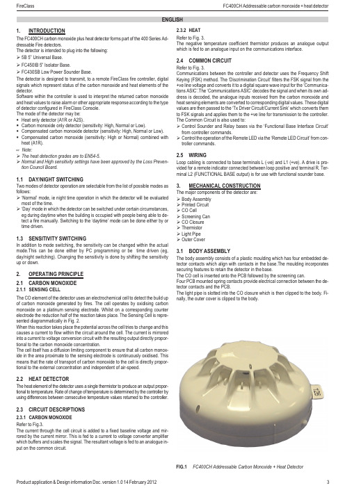
1.014201232.3.2HEAT Refer to Fig.3.The negative temperature coefficient thermistor produces an analogue output which is fed to an analogue input on the communications interface.2.4COMMON CIRCUITRefer to Fig.3.Communications between the controller and detector uses the Frequency Shift Keying (FSK)method.The ‘Discrimination Circuit’filters the FSK signal from the +ve line voltage and converts it to a digital square wave input for the ‘Communica-tions ASIC’.The ‘Communications ASIC’decodes the signal and when its own ad-dress is decoded,the analogue inputs received from the carbon monoxide and heat sensing elements are converted to corresponding digital values.These digital values are then passed to the ‘Tx Driver Circuit/Current Sink’which converts them to FSK signals and applies them to the +ve line for transmission to the controller.The Common Circuit is also used to:ØControl Sounder and Relay bases via the ‘Functional Base Interface Circuit’from controller commands.ØControl the operation of the Remote LED via the ‘Remote LED Circuit’from con-troller commands.2.5WIRINGLoop cabling is connected to base terminals L (-ve)and L1(+ve).A drive is pro-vided for a remote indicator connected between loop positive and terminal R.Ter-minal L2(FUNCTIONAL BASE output)is for use with functional sounder base.3.MECHANICAL CONSTRUCTIONThe major components of the detector are:ØBody Assembly ØPrinted Circuit ØCO CellØScreening Can ØCO Closure ØThermistor ØLight Pipe ØOuter Cover3.1BODY ASSEMBLYThe body assembly consists of a plastic moulding which has four embedded de-tector contacts which align with contacts in the base.The moulding incorporates securing features to retain the detector in the base.The CO cell is inserted onto the PCB followed by the screening can.Four PCB mounted spring contacts provide electrical connection between the de-tector contacts and the PCB.The light pipe is slotted into the CO closure which is then clipped to the body.Fi-nally,the outer cover is clipped to the body.1.INTRODUCTIONThe FC400CH carbon monoxide plus heat detector forms part of the 400Series Ad-dressable Fire detectors.The detector is intended to plug into the following:Ø5B 5”Universal Base.ØFC450IB 5”Isolator Base.ØFC430SB Low Power Sounder Base.The detector is designed to transmit,to a remote FireClass fire controller,digital signals which represent status of the carbon monoxide and heat elements of the detector.Software within the controller is used to interpret the returned carbon monoxide and heat values to raise alarm or other appropriate response according to the type of detector configured in FireClass Console.The mode of the detector may be:§Heat only detector (A1R or A2S).§Carbon monoxide only detector (sensitivity:High,Normal or Low).§Compensated carbon monoxide detector (sensitivity:High,Normal or Low).§Compensated carbon monoxide (sensitivity:High or Normal)combined with heat (A1R).+Note:ØThe heat detection grades are to EN54-5.ØNormal and High sensitivity settings have been approved by the Loss Preven-tion Council Board.1.1DAY/NIGHT SWITCHINGTwo modes of detector operation are selectable from the list of possible modes as follows:Ø‘Normal’mode,ie night time operation in which the detector will be evaluated most of the time.Ø‘Day’mode in which the detector can be switched under certain circumstances,eg during daytime when the building is occupied with people being able to de-tect a fire manually.Switching to the ‘daytime’mode can be done either by or time driven.1.3SENSITIVITY SWITCHINGIn addition to mode switching,the sensitivity can be changed within the actual mode.This can be done either by PC programming or be time driven (eg,day/night switching).Changing the sensitivity is done by shifting the sensitivity up or down.2.OPERATING PRINCIPLE 2.1CARBON MONOXIDE2.1.1SENSING CELLThe CO element of the detector uses an electrochemical cell to detect the build up of carbon monoxide generated by fires.The cell operates by oxidising carbon monoxide on a platinum sensing electrode.Whilst on a corresponding counter electrode the reduction half of the reaction takes place.The Sensing Cell is repre-sented diagrammatically in Fig.2.When this reaction takes place the potential across the cell tries to change and this causes a current to flow within the circuit around the cell.The current is mirrored into a current to voltage conversion circuit with the resulting output directly propor-tional to the carbon monoxide concentration.The cell itself has a diffusion limiting component to ensure that all carbon monox-ide in the area proximate to the sensing electrode is continuously oxidised.This means that the rate of transport of carbon monoxide to the cell is directly propor-tional to the external concentration and independent of air-speed.2.2HEAT DETECTORThe heat element of the detector uses a single thermistor to produce an output propor-tional to temperature.Rate of change of temperature is determined by the controller by using differences between consecutive temperature values returned to the controller.2.3CIRCUIT DESCRIPTIONS2.3.1CARBON MONOXIDE Refer to Fig.3.The current through the cell circuit is added to a fixed baseline voltage and mir-rored by the current mirror.This is fed to a current to voltage converter amplifier which buffers and scales the signal.The resultant voltage is fed to an analogue in-put on the commoncircuit.ENGLISHFC400CH Addressable Carbon Monoxide +Heat DetectorFIG.14 1.01420124.5.1.2EFFECT OF AIRFLOW ON SENSITIVITYThe signal status of the FC400CH detector has been specifically designed to be in-sensitive to abnormal air velocities.The effect of normal air velocities upon sensi-tivity is negligible.4.5.1.3EFFECT OF TEMPERATURE ON SENSITIVITYThe carbon monoxide detector incorporates temperature compensation and its condition current will be substantially constant over its specified operating range.4.5.1.4EFFECT OF ATMOSPHERIC PRESSURE ON SENSITIVITYThe sensitivity of the detector is not effected by changes in atmospheric pressure unless they happen very quickly ie explosions.4.5.2RESPONSE TO FIRE TESTSThe response of the FC400CH carbon monoxide detection element of the detector to real or large-scale test fires will be dependent on the detection mode chosen and the sensitivity set in the control unit.Other factors however,such as the rate of development of the fire,and relative ox-ygen supply are also important.The fire tests defined in prEN54pt.7which are in-tended for ionisation and optical detectors are less appropriate for carbon monoxide fire detectors as their design means that they produce significant levels of carbon monoxide only in their later stages.However,the FC400CH using compensated carbon monoxide combined with A1R heat (sensitivity High and Normal)mode,pass all tests laid down in prEN54pt 7including the fire tests.4.5.3HEAT DETECTOR4.5.3.1GENERALThe performance of heat detectors is defined in European Standard prEN54-5.5.DETECTOR ADDRESSThe loop address of the detector is held in internal E 2PROM which is pro-grammed from the FC490ST Address Programmer.+Note:this device use one address only on the loop.6.ADDRESS FLAGRefer to Fig.6.The address flag is used to identify the address and zone of the de-tector.The address flags are supplied in one of two packs (address 1-127or 128-255,with a different colour for each loop)and are ordered separately from the detector.The address flag is fitted to the bottom of the detector.When the detector is fitted to the base and turned until fully located the address flag is then transferred to the base.If the detector is removed from the base,the address flag remains with the base.7.ORDERING INFORMATIONFC400CH Carbon Monoxide +Heat detector.Address Flag Labels -Loop A (White).Address Flag Labels -Loop B (Yellow).8.RECYCLING INFORMATIONCustomers are recommended to dispose of their used equipments (panels,detec-tors,sirens,and other devices)in an environmentally sound manner.Potential methods include reuse of parts or whole products and recycling of products,com-ponents,and/or materials.9.WASTE ELECTRICAL AND ELECTRONIC EQUIPMENT (WEEE)DIRECTIVEIn the European Union,this label indicates that this product should NOT be disposed of with household waste.It should be deposited at an appropriate facility to enable recovery and recycling.The manufacturer reserves the right to change the technical specifications of this product without prior notice.4.TECHNICAL SPECIFICATION4.1MECHANICALDimensions:The overall dimensions are shown in Fig.5(less base ).MaterialsBody,cover,and closure:FR110‘BAYBLEND’flame retardant.Weight Detector:0.088kg Detector +Base:0.152kg4.2ENVIRONMENTALTemperature Operating:-0oC to +55oC Storage:-20o C to +55oC+The detector may be operated for short periods between the limits of 0oC to -20oC but with reduced performance.+The detector may be operated for short periods between the limits +55oC to+70o C,prolonged use between these limits will degrade the performance and shorten the life of the detector.Relative Humidity:95%(non-condensing )Shock:Vibration:prEN54Pts.5and 7Impact:Corrosion:prEN54Pts.5and 7The detectors comply with Lloyd’s Register Test Specification Number 1(1996).Environmental Category ENV2plus Salt Mist test.4.3ELECTROMAGNETIC COMPATIBILITYThe detector complies with the following:Øproduct family standard EN50130-4in respect of Conducted Disturbances,Radi-ated Immunity,Electrostatic Discharge,Fast Transients and Slow High Energy;ØEN50081-1for Emissions.4.4ELECTRICAL CHARACTERISTICSThe following characteristics (Table 1)apply at 25o C and nominal supply voltage of 37.5V unless otherwise specified.Table 1:Electrical Characteristics*No remote indicator fittedAddressable circuit voltage:40V dc max.with addressable waveform (polarity conscious).4.5PERFORMANCE CHARACTERISTICS4.5.1CARBON MONOXIDEThe FC400CH carbon monoxide sensing element with base,forms an address-able detector which transmits,to remote equipment,signals representing the state of the sensing cell.The control equipment evaluates these signals against prede-termined criteria and decides when an alarm condition should be signalled.The in-formation given below therefore relates to the performance of the carbon monoxide element of the detector simply as a transducer,since the system alarm response is determined by the control unit.4.5.1.1RESPONSE TO CARBON MONOXIDEThe response to carbon monoxide will vary from detector to detector.For this rea-son each detector is characterised on manufacture and calibration values are stored in the internal detector memory.The controller will then normalise the out-put signal from the detector such that the output is equivalent to 2.5bits/ppm car-bon monoxide above a threshold of 20bits.Carbon monoxide may be present in some environments under certain circumstances (high values of pollution or ex-treme environmental conditions).However,the deviation is unlikely to be signifi-cant compared with the alarm threshold level.Schema a blocchi semplificato del rilevatoreSimplified Block Schematic Diagram of detectorFIG.3Vereinfachte Block-Schemadarstellung des Melders FC400CHELETTROLITAELECTROLYTEELEKTROLYTELETTRODO CONTATORECOUNTER ELECTRODEGEGENELEKTRODEELETTRODO ATTIVOSENSING ELECTRODEMESSELEKTRODE BARRIERA DI DIFFUSIONEDIFFUSION BARRIERDIFFUSE BARRIERECONTATTICONTACT PINSANSCHLUSSSTIFTE Schema del sensoreRepresentational Diagram of CO Sensing CellFIG.2Diagramm der CO-Messzelle120.415.966D o c .v e r s i o n 1.0S h e e t 114.F e b r u a r y 12–S u b j e c t t o c h a n g e w i t h o u t n o t i c e .I S T S U B L 3F C 400C H 1.0140212V 1BLOCCAGGIO DEPRESSIONSDI MONTAGGIO RECESS SAGOMATA A ´D`PART A ´U`CHANNEL SPORGENZE RETAINING Inserimento della linguetta indirizzo FIG.6Fitting Address LabelCarrierDimensioni generali del rilevatore FC400CH Overall Dimensions of FC400CH detector FIG.5Abmessungen des MeldersFC400CHSezione e vista superiore del rilevatore Sectioned and Top View of the detector FIG.4Schnittdarstellung und Ansicht von oben©FireClassVia Gabbiano 22,Z.Ind.S.Scolastica 64013Corropoli (TE),ItalyHillcrest Business Park Cinderbank Dudley West Midlands DY29AP United Kingdom **************************。
学生用fx-991MS卡西欧计算器使用说明书
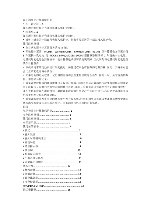
取下和装上计算器保护壳•在开始之前 (1)如图所示握住保护壳并将机体从保护壳抽出。
•结束后 (2)如图所示握住保护壳并将机体从保护壳抽出。
•机体上键盘的一端必须先推入保护壳。
切勿将显示屏的一端先推入保护壳。
使用注意事项•在首次使用本计算器前务请按5 键。
•即使操作正常﹐MODEx。
115MS/MODEx。
570MS/MODEx。
991MS 型计算器也必须至少每3 年更换一次电池。
而MODEx。
95MS/MODEx。
100MS型计算器则须每2 年更换一次电池。
电量耗尽的电池会泄漏液体﹐使计算器造成损坏及出现故障。
因此切勿将电量耗尽的电池留放在计算器内。
•本机所附带的电池在出厂后的搬运﹑保管过程中会有轻微的电源消耗。
因此﹐其寿命可能会比正常的电池寿命要短。
•如果电池的电力过低﹐记忆器的内容将会发生错误或完全消失。
因此﹐对于所有重要的数据﹐请务必另作记录。
•避免在温度极端的环境中使用及保管计算器。
低温会使显示画面的反应变得缓慢迟钝或完全无法显示﹐同时亦会缩短电池的使用寿命。
此外﹐应避免让计算器受到太阳的直接照射﹐亦不要将其放置在诸如窗边﹐取暖器的附近等任何会产生高温的地方。
高温会使本机机壳褪色或变形及会损坏内部电路。
•避免在湿度高及多灰尘的地方使用及存放本机。
注意切勿将计算器放置在容易触水受潮的地方或高湿度及多灰尘的环境中。
因如此会损坏本机的内部电路。
目录取下和装上计算器保护壳 (1)安全注意事项 (2)使用注意事项 (3)双行显示屏 (7)使用前的准备 (7)k模式 (7)k输入限度 (8)k输入时的错误订正 (9)k重现功能 (9)k错误指示器 (9)k多语句 (10)k指数显示格式 (10)k小数点及分隔符 (11)k计算器的初始化 (11)基本计算 (12)k算术运算 (12)k分数计算 (12)k百分比计算 (14)k度分秒计算 (15)kMODEIX, SCI, RND (15)记忆器计算 (16)k答案记忆器 (16)k连续计算 (17)k独立记忆器 (17)k变量 (18)科学函数计算 (18)k三角函数/反三角函数 (18)Ch。
除碳器说明书

除碳器说明书篇一:除二氧化碳器说明书除二氧化碳器Instruction for Decarbonator使用说明书Operation Instruction Manual无锡电站辅机厂Wuxi Power Auxiliary Equipment Works一、用途除二氧化碳器是用于驱除在水中的软化~除盐过程中~原水经过氢离子交换后~水中的重碳酸被破坏而产生的大量游离二氧化碳的设备~它设置于氢离子之后。
可以去除水中的二氧化碳~减少对设备的腐蚀~减轻阴离子交换的负荷~提高水处理设备系统的经济性与出水水质。
二、主要技术数据工作压力:常压工作温度:常温淋洒密度:60米3/米2时进水温度:15?进水CO2含量:?390毫克/升出水CO2含量:?5毫克/升三、工作原理当含有H2CO3的水通过进水装置均匀地从容器顶部往下流过填料层时~水在填料的表面形成一种薄膜的流动~薄膜的流动造成了水中CO2和容器底部鼓进来的空气密切接触的条件~使水中气体与空气中气体容易自由交换~由于空气里的CO2含量很小~它的压力只占大气压力的0.003%左右~所以~水中的CO2就很容易扩散到空气里去~当水逐渐往下流动时~它所接触的却是比较新鲜的空气(因空气向上流动~越到容器上部~空气里吸收的CO2越多。
“新鲜”指空气中所吸收的CO2较少)更有利于CO2扩散出来~水流至底部时~水里的绝大部分CO2已被去除~残余的CO2含量在5毫克/升左右。
四、结构简述1. 进水装置:采用支管式结构~用硬聚氯乙稀管或不锈钢管制作。
2. 多孔板及填料:多孔板:小直径设备上采用硬聚氯乙稀板制作~大直径设备上采用钢板衬胶。
填料:采用Φ25×25×3陶瓷环或Φ50聚丙烯塑料空心多面球。
3. 进水管管径的选择按2米/秒流速考虑。
4.五、使用方法1. 启动和供水(1) 启动清水泵~开启投运的阳离子交换器运行进水门和空气门~待空气放尽关闭空气门。
开启该交换器疏水门~顺流至水质符合规范~并检查没有跑树脂现象以后~即开启鼓风机~然后关闭疏水门~开启阳离子交换器出水门向除碳器进水~进行除碳工作。
TOC4100操作说明书
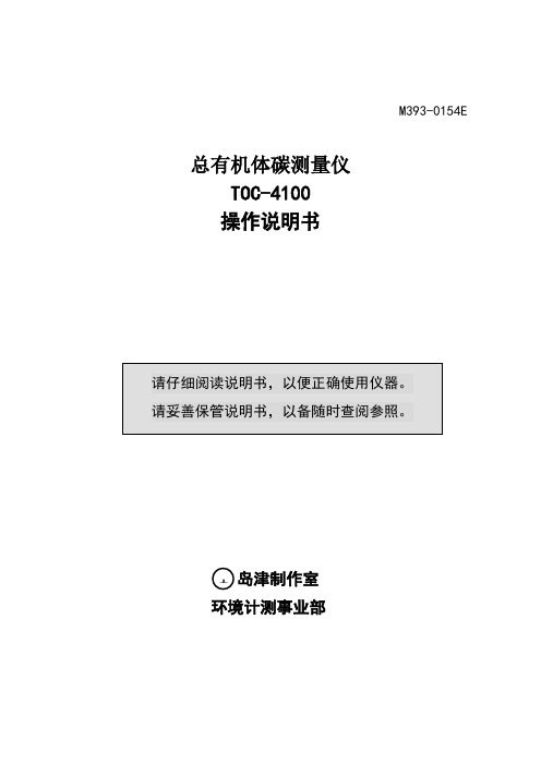
M393-0154E总有机体碳测量仪TOC-4100操作说明书岛津制作室环境计测事业部注意由于对设备内部的修理有危险,必须由经本公司专门训练的人员修理。
请勿擅自进行超出本说明书规定的维修范围的拆装和改装。
安全上的注意事项本设备未设防爆结构,请勿在危险地区使用。
点源请使用AC100±10V。
1.前言首先,为您采用总有机体碳测量仪TOC-4100表示感谢。
TOC-4100是根据作为TOC测定法JIS*等方面广泛使用的“燃烧氧化—红外线分析法”原理,测定水中碳量的装置。
为能正确使用本装置,请在使用前仔细阅读本操作说明书,读后,请放在需要时随时可取的地方妥善保存。
※有关的JIS规格JIS K-0102 《工厂排水试验方法》JIS K-0805 《有机体碳(TOC)自动测量器》JIS K-0551 《超纯水中的有机体碳(TOC)试验方法》1.1使用上的注意事项使用本装置时,必须严格遵守下列注意事项。
运转时的注意事项1)电炉升温时,电炉中央部附近(燃烧管插入口附近)温度极高,绝对不要用手触摸。
<防止烫伤>2)电炉升温时,载气必须流通。
3)装置左侧面上连接排水出口的外部配管,尽量使用流量阻力小的配管,而且不要高于排水出口的位置。
用阻力大的配管会因排水不畅,造成装置内部溢出。
<防止部件腐蚀>维护检修时注意事项及其它1)装卸、更换燃烧管时,必须等到电炉温度降至室温以下再进行。
<防止烫伤>2)电炉未装燃烧管的状态下,电炉不要升温。
不得已升温时,试样注入口用部件(白色塑料部件),为避免受到来自炉心部(约680℃)的放射热而变形,应该先取下,或用石英等隔热材料将炉心部的孔盖住。
<防止部件损伤>3)安装连接8通阀和6通阀的各接头时,不能用手拧紧。
使用工具强拧紧时,内部的阀体会因力量过大而变形,造成阀内部修楼。
<防止损坏部件>4)往8通阀上连接配管,装卸试样管内部配管等,或驱动部分进行维修时,装置必须停止运转。
CZCQ-101充气泵说明书
CZCQ-101充气泵说明书
重要的安全指导:(注意:减少触电风险)
1、不要拆解产品。
不要尝试修理或者改变产品。
可提交给有资质的服务商进行所有产品的服务和修理。
2、不要将产品放在容易掉落或者有水或者任何液体的地方。
3、如果产品落入液体中,不要接触产品。
4、此产品只能使用12V直流电源
5、产品在使用过程中一定要全程有人监视。
警告:防止人受伤
6、避免儿童操作本产品。
当在儿童附近使用本产品时,一定要密切监督。
7、充气泵在使用时或者开始使用的时候会变得非常热,除了接触开关键外,在使用中禁止用手触碰泵的任何部位。
8、禁止在火或者爆炸性气体或使用了气雾剂产品的操作场所使用本产品。
9、禁止在氧气管理的场所使用本产品。
10、禁止泵入空气以外的其它气体。
11、禁止在困倦的时候操作本产品。
12、禁止将充气泵给未知最大允许气压的物品充气。
*?禁止将充气泵喷嘴朝向任何人或者人体任何部位。
13、本充气泵装备了自动复位温度保护装置,当温度保护器复位时,充气泵将自动断电停止工作。
14、操作充气泵时请带上安全手套或护目镜。
15、请在通风的场地使用本产品。
操作指南:
请仔细阅读本操作指南,确保您能享受到本产品的便利以及和正确使用本产品。
FUHO 101.06 操作手冊说明书
计算器按键的使用说明
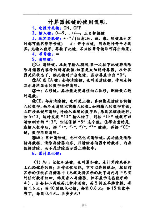
计算器按键的使用说明.1、电源开关键:ON、OFF2、输入键:0—9、. +/—:正负转换键3、运算功能键:+ - * / (注意:加、减、乘、除键在计算时都可能代替等号键) √:开平方键,用来进行开平方运算。
先输入数字,再按下此键,不必按等号键即可得出结果。
4、等号键:=5、清除键:①C:清除键。
在数字输入期间,第一次按下此键将清除除存储器内容外的所有数值.如果是太阳能计算器,在计算器关闭状态下,按此键则开启电源,显示屏显示出“0”。
②AC或CA键:全部清除键,也叫总清除键,作用是将显示屏所显示的数字全部清除。
③→:右移键。
其功能是荧屏值向右位移,删除最右边的尾数。
④CE:部分清除键,也叫更正键。
其功能是清除当前输入的数字,而不是清除以前输入的数。
如刚输入的数字有误,立即按此键可清除,待输入正确的数字后,原运算继续进行。
如5+13,这时发现“13”输入错了,则按“CE”键就可以清除刚才的“13”,但还保留“5”这个数。
值得注意的是,在输入数字后,按“+”、“-”、“/”、“*”键的,再按“CE”键,数字不能清除。
⑤MC:累计清除键,也叫记忆式清除键。
其功能是清除储存数据,清除存储器内容,只清除存储器中的数字,内存数据清除,而不是清除显示器上的数字。
6、累计显示键:(1)M+:记忆加法键,也叫累加键。
是计算结果并加上已经储存的数;用作记忆功能,它可以连续追加,把目前显示的值放在存储器中(也就是将显示的数字与内存中已有的任何数字相加,结果存入存储器,但不显示这些数字的和)。
如去和小商贩买几种冰淇凌,买5筒五羊牌雪糕,每筒1.6元;买10筒绿色心情,每筒0.8元;买15筒蒙牛布丁,每筒0.4元。
共多少元?如先输入“5×1.6”→按“M+”键(把“5×1.6”的结果计算出来并储存起来)→然后输入“10×0.8”→按“M+”键(把“10×0.8”的结果计算出来并和前面储存的数相加)→接着输入“15×0.4”→按“M+”键(把“15×0.4”的结果计算出来并和前面储存的数相加)→最后按“MR”键(把储存的数全部取出来)→则出结果“22”(2)M-:记忆减法键,也叫累减键。
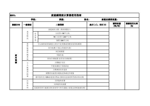
碳排放计算器使用指南
个 人 交 通
交 通 用 具 类 型 交 通 工 具 类 型
标准轿车(小排量车辆) SUV汽车(大排量车辆) 柴油车(各类柴油车) 摩托车 自行车 火车 公交车(站与站间距约0.8公里) 地铁(站与站间距约1.8公里) 出租车(计价器显示数据) 双动力汽车(混合型即节能型汽车)
公 共 交 通 商 务 交 通 出 差 、 旅 游 等 ) (
姓名:
家庭总碳排放量:
碳排放量 (吨/年) 能源使用比例 (%)
能源分布
一级指标
是打(√);否打(*)
家 用 能 源
一级指标
二级指标
双动力汽车(混合动力车即节能汽车)
年度交通公里数 (天数 *日公里数)
碳排放量 (吨/年)
能源使用比例(%)
地 面 交 通 计 算 家 庭 全 部 成 员 的 综 合 使 用 情 况 ) 空中交通(所 有成员) (
附件3:
家庭碳排放计算器使用指南
学校: 班级:
二级指标
家庭成员人数(填具体数字) 基 本 情 况 家 庭 能 源 供 暖 系 统 个 人 能 源 消 耗 量 环 保 科 技 住 房 类 型 小房型≤90平方米 90<大房型≤200平方米 别墅>200平方米 空心墙和屋顶保暖层(居住不是顶楼或顶楼有屋顶的都算) 防风装置(门窗之间装防风条) 双层玻璃窗 节能灯泡 附加空调装置(家里有空调就算) 习惯随手关灯 不使电器处于待机状态 习惯淋浴而非盆浴 调整居室温度以避免过热或过冷现象 循环使用至少30%家庭废旧物品(报纸及包装材料等的回收比例) 太阳能热水器 太阳能发电装置 家庭使用再生能源比例(绿电等可再生能源占家庭总消耗能源比例)
交 通 工 具 类 型
标准轿车(小排量车辆) SUV汽车(大排量车辆) 柴油车(各类柴油车) 摩托车 自行车 火车
- 1、下载文档前请自行甄别文档内容的完整性,平台不提供额外的编辑、内容补充、找答案等附加服务。
- 2、"仅部分预览"的文档,不可在线预览部分如存在完整性等问题,可反馈申请退款(可完整预览的文档不适用该条件!)。
- 3、如文档侵犯您的权益,请联系客服反馈,我们会尽快为您处理(人工客服工作时间:9:00-18:30)。
碳足迹计算器使用说明书
(CFC-101)
北京凯来美气候技术咨询有限公司
计算器界面简介
CFC-101碳足迹计算器使用说明书本计算器是一款革命性产品,专为低碳人士设计开发,在具备常规计算器功能的基础上,独创性地载入碳足迹计算功能,将人们在日常生活中“衣、食、住、行、用”各生活要素的消费数量换算成碳足迹数量,以判别其对环境的友好程度。
本计算器通俗易懂、简明扼要、老少咸宜,不仅是一款普及低碳知识,推动节能减排的科普工具,更是人们手边一款难得的多功能计算设备。
本计算器计算参数来源于科技部《全民节能减排手册》和国家发改委能源所。
本计算器具备碳足迹计算和常规办公计算两个模式,默认为常规办公计算模式,要进行碳足迹计算需通过“CO2”键切换。
在下面的章节中进行针对性介绍。
1.按键简介
2.碳足迹计算模式
您可以在按“ON/OFF”键开机进入常规计算模式后按“CO2”切换至碳足迹计算模式进行碳足迹计算。
●按相应功能键后“衣、食、住、行、用”中与其对应的图标和单位亮起,输
入消费数量后按“=”键即可得出该消费数量对应的碳足迹值(得出的碳足迹值同时还会被记入内存里)。
●选择其他功能键进行相应的碳足迹计算(得出的碳足迹值同样也被累加进内
存里)。
●计算完毕后按“ALL/DATE”键可以循环显示“衣、食、住、行、用”的碳足
迹合计值、各自的小计值(显示在下行)及其所占合计值的比例(显示在上行)。
●按“TREE”键显示消除碳足迹所需植树棵数。
若需要进行新一轮碳足迹计算,可以按“AC”键使显示屏以及内存清零,或按“ON/OFF”键关开机后再按“CO2”键重新进入碳足迹计算模式。
计算实例:计算某人购买衣服5件、饮用白酒20Kg、用电1000度、驾驶小轿车5000Km以及使用一次性筷子200双所产生的碳足迹。
3.常规计算模式
您可以在开机后直接进入常规计算模式进行常规计算。
3.1四则运算
3.2记忆操作及利率和税率计算
●M+:将显示屏上的数字与内存中的数字相加;
●M-:将内存中的数字与显示屏上的数字相减;
●MR:调用内存中的数据;
●MC:清除内存中的数据;
●MU:按下该键将进行利率和税率计算;
关于"MU"的用法如下:
3.3百分比计算
4.注意事项
请详细阅读以下使用注意事项,并将本说明书存放在易于取阅的位置以便日后随时查用。
4.1 安全注意事项
⏹电池
●安装电池时,电池正负极方向务必放置正确。
●若电池出现漏液,请及时取出以避免漏液损坏周围的零件甚至造成火灾及伤
人事故。
●若长时间不使用计算器,请将电池取出
●从计算器中取出的电池,务必将其放置于儿童无法触及的安全地方,防止被
意外吞食。
●万一电池被儿童意外吞食,请立即求医救治。
●该计算器使用了双重电源:一种为太阳能电源,另一种是纽扣电池电源。
在
外部光源较暗的情况下,当所记忆数据自行消失或者显示屏上数字变淡,且按“ON/OFF”键关机再开机后也无法恢复原来的亮度,若将计算器移至有足够亮度的外部光源下,显示屏又恢复原来的亮度时,则说明电池即将没电,请及时更换新的电池。
●切勿对电池充电、拆卸或使电池短路,更不要直接加热或焚烧电池。
●请使用指定的电池
●请把废旧电池集中放入废旧电池回收箱,以便集中处理。
⏹计算器的处理
●请勿焚烧本计算器,避免部分零件因焚烧而发生爆炸而导致火灾及伤人事件。
●请将报废的计算器放置于回收箱中,切勿随意丢弃本计算器。
4.2 使用注意事项
⏹计算器的使用
●请勿碰触内部零件,避免撞击、掉落、压折以及过重地压迫按钮。
同时避免
在极端温度、过高湿度以及多灰尘的环境使用或保存本计算机。
●请勿随意拆卸本计算机。
●在您开始常规计算前,请先确认是否按下ON/OFF键,使计算器开机,同时
请确认显示屏中下行是否显示出“0”。
●在进行碳足迹计算前,请先确认在开机前提下,是否按下CO2键,使计算器
进入到碳足迹模式,同时请确认显示屏上行是否显示出“0”,下行“0”消失,显示屏左方显示“CO2”及“Kg”。
⏹计算器的清洁
●请勿使用石油精、油漆稀释剂、苯类等挥发性液体清洁本计算器。
⏹计算器输入数据的更正
●在数据输入后,按“计算符号键”或按“=”键之前发现输入的数据有误时,
按“→”键,从末位的数值开始逐个消除,然后再度输入正确的数据进行计算。
或者,按“CE”键清除当前输入,再度输入正确的数据进行计算。
亦或按“AC”键清除以前所有输入并重新计算。
⏹计算器报错与解除方法
当计算器计算结果超过容量或计算逻辑错误时,在屏幕左方会出现“E”,同时会停止此后的计算。
●报错出现的情况:
1)两种模式下,无论是中途、最终结果或内存内的总和达到或超过1×10¹²时。
2)常规计算模式下,计算过程中出现不合数学逻辑的计算时(如任意数除以“0”)。
3)碳足迹计算模式下,未作任何碳足迹计算,按ALL/DATE键两次时。
●报错解除方法:
上述三种报错情况出现时,可按AC键,在系统内存清空、系统清零后重新进行计算。
或按CE键,“E”消失,同时系统解除不可操作模式,您可以在解除报错后显示的数值的基础上进行操作。
亦或按“ON/OFF”键关机再开机后重新计算。
⏹计算器自动关机
●计算器在无任何操作情况下放置5分钟左右时间后会自动关机,同时内存中
的数据将会清零。
此时按“ON/OFF”键则重新开机。
⏹计算器死机
●若计算器出现无法进行任何输入、按ON/OFF键无法开关机、模式无法切换、
显示屏上数字出现乱码等情况,说明计算机死机。
您可以使用细长的物体,插入计算器背面中间下方的圆孔内,按下“RESET”按钮后即可完成计算器重置。
(完)。