SystemVerilog快速入门PPT课件
SystemVerilogveriflcation精品PPT课件
Verilog
System Verilog
It uses the “always” procedure to represent Sequential logic Combinational logic Latched logic
What is SystemVerilog?
System verilog is the superset of verilog It supports all features of verilog plus add on features It’s a super verilog additional features of system verilog will be discussed
1. Writing Testbenches using SystemVerilog - Janick Bergeron
2. Verification Methodology Manual - Janick Bergeron
3. SystemVerilog For Verification - Chris Spear
What is SystemVerilog?
What is SystemVerilog?
SystemVerilog is a hardware description and Verification language(HDVL) SystemVerilog is an extensive set of enhancements to IEEE 1364 Verilog-2001 standards It has features inherited from Verilog HDL,VHDL,C,C++ Adds extended features to verilog
Verilog语法基础PPT教案学习

#10 num <= rega << 5 ; // num =
01_1000_0000
#10 regb <= rega << 5 ; // regb =
1000_0000
#20 num <= rega >> 3; // num =
00_0000_0001
#20 regb <= rega >> 3 ; // regb =
x
to b");
x
else $display(" a is not
equal to b");
a = 2'b1x;
z
b = 2'b1x;
0
if (a === b)
0
$display(" a is
0
identical to b");
1
else
$display(" a is not
Case等只i能d用e于nt行i为ca描l述t,o不b能"用);于RTL描述。
regc; reg val;
initial begin rega = 4'b0011; regb = 4'b1010; regc = 4'b1x10;
end initial fork
#10 val = rega == regb ; // val = 0
#20 val = rega != regc; // val = 1
第9页/共72页
注意逻辑等与 case等的差别 2‘b1x==2’b0x
值为0,因为不相等 2‘b1x==2’b1x
值为x,因为可能不 相等,也可能相等
FPGA入门培训教材共45张PPT课件
# STEP#4: run router, report actual utilization and timing, write checkpoint design, run drc, write verilog and xdc out route_design write_checkpoint -force $outputDir/post_route report_timing_summary -file $outputDir/post_route_timing_summary.rpt report_timing -sort_by group -max_paths 100 -path_type summary -file $outputDir/post_route_timing.rpt report_clock_utilization -file $outputDir/clock_util.rpt report_utilization -file $outputDir/post_route_util.rpt report_power -file $outputDir/post_route_power.rpt report_drc -file $outputDir/post_imp_drc.rpt write_verilog -force $outputDir/bft_impl_netlist.v write_xdc -no_fixed_only -force $outputDir/bft_impl.xdc
Verilog 有限状态机设计 ppt课件

第八章 有限状态机设计
Verilog 有限状态机设计
MOORE状态机 MEALY状态机 有限状态机的几种描述方式 有限状态机的状态编码
8.1 有限状态机
构成
组合逻辑 状态译码、产生输出 时序逻辑 存储状态
分类
Moore 输出是现态的函数 Mealy 输出是现态和输入的函数
always @(state) /*该过程产生输出逻辑*/
begin case(state) S3: z=1'b1; default:z=1'b0;
endcase end endmodule
“101”序列检测器(单过程描述)
module fsm4_seq101(clk,clr,x,z); input clk,clr,x; output reg z; reg[1:0] state; parameter S0=2'b00, S1=2'b01, S2=2'b11, S3=2'b10;/*状态编码,采用格雷(Gray)编码方 式*/
parameter S0=2'b00,S1=2'b01,S2=2'b11,S3=2'b10;
/*状态编码,采用格雷(Gray)编码方式*/
always @(posedge clk or posedge clr) /*该过程定义当前状态*/
begin
if(clr) state<=S0; //异步复位,s0为起始状态
(1)用三个过程描述:即现态(CS)、次态(NS)、 输出逻辑(OL)各用一个always过程描述。
(2)双过程描述(CS+NS、OL双过程描述):使用两 个always过程来描述有限状态机,一个过程描述现态和次 态时序逻辑(CS+NS);另一个过程描述输出逻辑(OL)。
Verilog的讲义52页PPT
0
0x
9
9.40ns
9
01
10
10.00ns 10
11
19
19.40ns 19
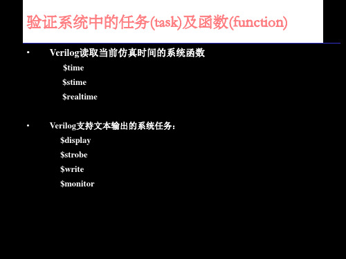
显示信号值 — $display
• $display输出参数列表中信号的当前值。 语法:$display([“ format_specifiers”,] <argument_ list>)
• $display输出时自动换行。
%m %t
hex octal decimal binary ASCII string strength module time
转义符
\t \n \\
\" \< 1-3 digit octal number> %0d
tab 换行 反斜杠 双引号 上述的ASCII表示 无前导0的十进制数
显示信号值—$write和$strobe
9.53ns
initial
10
01
begin
10 10.00ns 10
11
$display("time realtime20stime19\.t53ns
20
in1 \t o1 ");
10
$timeformat(-9, 2, "ns", 10);
$monitor("%d %t %d \t %b \t %b", $time, $realtime,
• $write与$display相同,不同的是不会自动换行。
$write($time, “%b \t %h \t %d \t %o \t”, sig1, sig2, sig3, sig4);
• $strobe与$display相同,不同的是在仿真时间前进之前的信号值。 而$display和$write立即显示信号值。也就是说$strobe显示稳定状态 信号值,而$display和$write可以显示信号的中间状态值。
System-Verilog-与功能验证分析

功能验证技术和方法学概要
功能验证技术和方法学概要
激励产生形式 1)用户直接输入,即直接测试(direct test)。 2)种子随机生成,即随机测试(random test)。 3)用户可控的随机输入,即约束随机测试 (constraint random test)
实际项目中我们通常三者结合着去检查比对结果。
功能验证技术和方法学概要
功能验证流程 验证过程可以被分解成三个主要阶段: 1)制定验证策略和验证计划; 2)创建验证平台,运行和调试; 3)覆盖率分析和回归测试。
功能验证技术和方法学概要
制定验证策略和验证计划
功能验证技术和方法学概要
创建验证平台,运行和调试;
System Verilog 与功能验证
功能验证技术和方法学概要
为什么需要IC验证 IC设计复杂度巨大,规模已达上亿门级。 70%验证, 30%设计。 验证是IC设计的关键部分。
功能验证技术和方法学概要
功能验证技术和方法学概要
什么是验证 验证是确保设计和预定的设计期望一致(吻合) 的过程。
功能验证技术和方法学概要
覆盖率驱动验证 覆盖率驱动验证方法学涉及以下技术: 事务级验证、约束随机激励产生、自动化结果 比较、覆盖率统计分析和直接测试。
功能验证技术和方法学概要
事务级验证 事务级验证允许在一个更高的抽象层次来创建 验证场景。 信号级VS事物级:低效VS高效,简单VS复杂。
功能验证技术和方法学概要
功能验证技术和方法学概要
覆盖率分析和回归测试
功能验证技术和方法学概要
verilog数字系统设计教程PPT课件

• 复杂数字系统的构成; • 基本电路和 Verilog 的对应关系; • 同步有限状态机在电路中的作用; • 时钟树与自动综合技术
数字逻辑电路的构成
- 组合逻辑:输出只是输入逻辑电平的函
数(有延时),与电路的原始状态无关。
• 时序逻辑:输出不只是输入的逻辑电
平的函数,还与电路所处的状态有关。
8 ‘ d 31
8‘d
t
out[15:0]
202
16 ‘ d
16‘ d
t
Sn 开
93
606
t 关
全局时钟网和平衡树结构
触发器1
全局时钟网络 触发器 图1 全局时钟网示意图
缓冲器
触发器n
图2 平衡树结构示意图
避免冒险和竞争
• 由于组合逻辑和布线的延迟引起
a
c
b
a
b
t
c
t
clock
避免冒险和竞争与流水线
t
t
带寄存器的八位数据通路控制器的波形
ControlSwitch
in[7]
out[7]
CLOCK
out[7]
D Q[7]
ControlSwitch
in[0]
out[0]
CLOCK
out[0]
D Q[0]
带寄存器的八位数据通路控制器的Verilog描述
`define ON 1 ‘b 1 `define OFF 1 ‘b 0 wire ControlSwitch; wire clock wire [7:0] out, in;
ControlSwitch in[7]
out[7]
…... …...
in[0]
SystemVerilog Assertions (SVA) EZ-Start Guide英文精品课件
SystemVerilog Assertions (SVA) EZ-Start GuideAugust 2006© 1995-2006 Cadence Design Systems, Inc. All rights reserved.Printed in the United States of America.Cadence Design Systems, Inc., 555 River Oaks Parkway, San Jose, CA 95134, USATrademarks: Trademarks and service marks of Cadence Design Systems, Inc. (Cadence) contained in this document are attributed to Cadence with the appropriate symbol. For queries regarding Cadence’s trademarks, contact the corporate legal department at the address shown above or call 800.862.4522.All other trademarks are the property of their respective holders.Restricted Print Permission: This publication is protected by copyright and any unauthorized use of this publication may violate copyright, trademark, and other laws. Except as specified in this permission statement, this publication may not be copied, reproduced, modified, published, uploaded, posted, transmitted, or distributed in any way, without prior written permission from Cadence. This statement grants you permission to print one (1) hard copy of this publication subject to the following conditions:1.The publication may be used solely for personal, informational, and noncommercial purposes;2.The publication may not be modified in any way;3.Any copy of the publication or portion thereof must include all original copyright, trademark, and otherproprietary notices and this permission statement; and4.Cadence reserves the right to revoke this authorization at any time, and any such use shall bediscontinued immediately upon written notice from Cadence.Disclaimer: Information in this publication is subject to change without notice and does not represent a commitment on the part of Cadence. The information contained herein is the proprietary and confidential information of Cadence or its licensors, and is supplied subject to, and may be used only by Cadence’s customer in accordance with, a written agreement between Cadence and its customer. Except as may be explicitly set forth in such agreement, Cadence does not make, and expressly disclaims, any representations or warranties as to the completeness, accuracy or usefulness of the information contained in this document. Cadence does not warrant that use of such information will not infringe any third party rights, nor does Cadence assume any liability for damages or costs of any kind that may result from use of such information.Restricted Rights: Use, duplication, or disclosure by the Government is subject to restrictions as set forth in FAR52.227-14 and DFAR252.227-7013 et seq. or its successor.SystemVerilog Assertions (SVA)EZ-Start GuideIn general, there are three components to efficient verification: stimulus generation, coverage, and checking. Cadence Design Systems, Inc. provides companion EZ-Start packages for each of these three areas. The focus of this EZ-Start package and its accompanying executable example is assertion-based verification (ABV). Specifically, dynamic ABV simulation using the SystemVerilog assertion language (SVA).This document is a self-guided introduction to using dynamic ABV and writing SVA. The following sections describe the three major steps involved in ABV:!Picking a focus area!Identifying behavior and mapping to property types!Implementing assertionsPicking a Focus AreaThe first step in ABV is to pick a focus area for your assertions. In general, you want to start with areas that are likely to contain bugs or that will benefit from additional visibility. For example, the following lists areas that typically have a good ROI for assertions and, therefore, represent good starting points for assertions.!Interfaces between blocks!Control logic that contains corner cases!Critical functions within the designNote: If the schedule permits, this list can be expanded to include other areas within the design.Identifying Behavior and Mapping to Property TypesAfter you choose a focus area, you can then identify interesting behavior within the focus area and then express them in natural language form. Once you have expressed the behavior in natural language form, you can map the behavior to various property types. A property is a description of the functional behavior of signals over time. An assertion states that a given property is an important aspect of the behavior of the design, and that the design must behave consistently with this property. Writing assertions starts with defining the properties of a design.The following table lists questions that can help identify the different types of properties in a design. Each of these questions map to a property type that can be used to create templates for your assertions.Table 1 Basic Questions and Property TypesQuestion Property TypeAre there signals that have a set behavior thatInvariantsmust occur independent of time?Bounded InvariantsAre there signals that have a set behavior thatmust occur within a certain time frame?Boundary CasesDoes the design contain boundary conditionsthat must trigger a set behavior?Bug IdentificationAre there ways to specify values or sequencesthat would describe an error condition?Signal ValuesIs the behavior of certain signals critical to thefunctionality of the design?Note: Although this set of questions is not exhaustive, it is a good starting point for developing assertions.The following sections describe each of these property types.InvariantsAn invariant is a condition that must always (or never) occur. Invariants are one of the easier property types to describe, because they do not involve time. Examples of invariants are:!One-hot signals!Boolean conditions that must always occur, or never occur!Special cases where an object must hold true, given a particular conditionBounded InvariantsA bounded invariant is a condition that must be invariant during a bounded period of time. Most often there are signals within the register transfer level (RTL) that can help identify this window of time. Otherwise, you can use auxiliary code to create a start and end signal that will identify this window and improve readability.Boundary CasesBugs often hide in boundary cases. You can develop an assertion that ensures a boundary condition produces the expected behavior.Bug IdentificationBug identification assertions describe behavior that must never occur in a design. The advantage of this type of assertion, opposed to describing behavior that must happen, is that RTL code does not get duplicated, which is usually a concern when you are writing RTL assertions.Signal ValuesOne of the most basic ways to describe a signal’s behavior is to identify when the signal:!Must have a value of 0 or 1!Transitions from 0 to 1, and from 1 to 0!Retains its current value!Changes valueIf this can be done without duplicating the RTL (or by a person other than the designer), then this is the most complete way to develop an assertion. This technique might be best for critical signals.Implementing AssertionsNow that you have selected your focus areas, extracted interesting behavior, translated that behavior into natural language form, and mapped the behavior to the various property types, you can express these property types in actual SVA syntax. Before doing this, you need to understand some basic SVA syntax.Basic SVA SyntaxThis section uses a sample Signal Value assertion to illustrate the fundamental SVA constructs.The following assertion is derived from the following natural-language statement: “If there is a rising edge on the request, then a grant must be issued within 1 to 3 cycles.”1. 2. 3. 4. 5. Figure 1 Sample Signal Value AssertionYou can then break down the example into the following:Assertion Label—Identifies the assertion. This is used for reports and debugging.(required)Directive— Specifies how the assertion is used during the verification process--as anassertion or constraint, or for collecting coverage information (required)Clocking—Indicates how or when the signals in the assertion are sampled (required)Disabling Condition—Disables the assertion during certain conditions (optional)Property Expressions (required)a. System Functions—Indicates one of the SVA system functions that are used toautomate some common operations. For example: $rose, $fell, $past, and$onehot. Refer to the “Writing SystemVerilog Assertions” chapter of the Assertion Writing Guide for information on the SVA system and sampled-value functions that are supported in the current release.b. Implication Operator ( |-> or |=>)—Specifies that the behavior defined on the right-hand side of the operator be checked only if the condition on the left-hand sideoccurs. There are two forms of the implication operator: overlapping (|->) and non-overlapping (|=>).The overlapping operator indicates that the last cycle of the LHS sequenceoverlaps the first cycle of the RHS sequence.The non-overlapping operator indicates that there is no overlap and that the firstcycle of the RHS sequence must occur one cycle after the LHS sequencecompletes.6.Note: When you are trying to capture an assertion in the standard written form,the implication operator typically maps to the word “then”.c. Cycle Operator (##)—Distinguishes between cycles of a sequence. Cycles arerelative to the clock defined in the clocking statement. Use a fixed number (##n) to specify a specific delay or a range operator (as specified in the next sub-bullet) to specify a range.d. Non-consecutive repetition operator ([*])—Enables the repetition of signals. Usethe form [*n] to represent a fixed repetition, or [*n:m]to specify a range ofrepetition from n to m. You can also apply the range operator to the cycleoperator.End of Statement Delimiter—Indicates the end of an assertion (required)Implementing Property TypesYou can leverage the syntax described in the previous section to create templates for each of the property types discussed earlier. The following table maps the different property types to SVA constructs that you can use in property expressions.Note: This table suggests SVA syntax that can be used in property expressions. This table does not cover the other aspects on an assertion, which were discussed in the previous section (such as assertion labels, directives, clocking, disabling conditions, and so on). Table 2 Property Types and SVA SyntaxQuestion Property Type Useful SVA SyntaxInvariant (onehot) $onehot(), $onehot0()Invariant (Illegal Combinations) ! (Boolean condition)Are there signals that are supposed to behave a certain way independent of time?Invariant (Special Cases) (special case) |-> (expected behavior) (special case) |=> (expected behavior)Are there signals that are supposed to behave a certain way within some window of time? BoundedInvariants(start) |-> ((!finish && cond)[*n:m] ##1finish && cond)(start) |-> ((!finish && cond)[*n:m] ##1finish)(start && !finish) |=> ((!finish &&cond)[*n:m] ##1 finish)Note: ##1 indicates a delimiter—not a 1-cycledelayAre there any boundary conditions in the design in which some behavior needs to be exhibited when that condition is reached? Boundary Cases (boundary case sequence) |-> (expectedsequence)Are there ways todescribe values orsequences that woulddescribe an errorcondition?Bug Identification Not (sequence)Are there signals that are critical to the functionality of the design? Signal Values (condition |=> $rose(sig))(condition |=> $fell(sig))(condition |=> sig == $past(sig))(condition |=> sig != $past(sig))Arbiter ExampleYou can now apply this ABV process to the arbiter example described in the Arbiter Specification,.which is included with this document. The arbiter example is typically a very good focus area for assertions, because it is control logic that often contains many corner case conditions.Mapping the BehaviorThe following lists arbiter example’s interesting behavior and maps this behavior to the various property types.Table 3 Arbiter Behavior MappingBehavior Property TypeGrant signals are zero one hot. InvariantOnce granted, the Busy signal must beasserted until Done.Bounded invariantThe arbiter must be fair for B. Boundary CasesYou must never see a GntB, when only ReqA is asserted.Bug IdentificationBusy must be asserted one cycle after agrant. Signal ValuesCreating the Assertion SyntaxAfter you map the behavior to a property type (Table 3), you can create the actual syntax for the assertion.! Invariant —Grant signals are zero one hot.assert_grant_zeroonehot : assert property (@(posedge clk) disable iff (!ResetN) $onehot0({GntA, GntB}));! Bounded invariant: Once granted, the Busy signal must be asserted until Done.assert_Busy_until_Done : assert property (@(posedge clk) disable iff (!ResetN) (GntA || GntB) |=> Busy[*0:$] ##1 Busy && Done); ! Boundary cases —The arbiter should be fair for B.assert_fair_for_B : assert property (@(posedge clk) disable iff (!ResetN)(GntA ##1 Busy[*0:$] ##1 Done&&ReqA&&ReqB |=> GntB));! Bug identification —You must never see a GntB, when only ReqA is asserted.assert_never_grant_wo_req : assert property (@(posedge clk) disable iff (!ResetN) not (ReqA && !ReqB ##1 GntB));! Signal values —Busy must be asserted one cycle after a grant.assert_Busy_active : assert property (@(posedge clk)disable iff (!ResetN) (GntA || GntB) |=> $rose(Busy)); Running the Assertions in the SimulatorUse the following steps to run these assertions in the Incisive Design Team Simulator:1. 2. 3. Go to the directory that contains the arbiter example:cd <example_install_dir>/iusUse the following command to run the example:run_simIn the console window, observe that the assertion –summary command shows that all the assertions have been executed, but one assertion fails.From the toolbar, click the Assertion Browser button . The Assertion Browserdisplays a flat list of all of the assertions in a design and provides the assertion’s name,4.5.6. module, instance, class, finished count, failed count, and so on. The assertions are listed in table format.Double-click any assertion. This displays the source code for the assertion. Notice how the assertions are embedded directly into the arbiter RTL file.Close the Source Browser.Select the assert_fair_for_B assertion. Add it to the waveform by selecting it and clicking on the Waveform button from the toolbar.Note: The waveform displays the state of the given assertion. The red circle indicates where the assertion fails and represents the starting point for debug.7. Using the steps discussed in this document and in the arbiter specification, you can addmore assertions to the <example install dir>/rtl/arbiter.v file and rerun.ConclusionThrough the course of this document, you have been exposed to an ABV process that uses SVA. This includes picking focus areas for assertions, identifying properties that are characteristic to the design, implementing assertions using SVA, and viewing assertions in a real example. After completing these steps, you can try implementing SVA in your own designs.。
systemVerilog快速入门PPT

第一讲: SystemVerilog 基本知识
夏宇闻
神州龙芯集成电路设计公司 2008
Verilog HDL的发展历史
1984: Gateway Design Automation 推出 Verilog 初版 1989: Gateway 被Cadence Design Systems 公司收购 1990: Cadence 向业界公开 Verilog HDL 标准 1993: OVI 提升 the Verilog 标准,但没有被普遍接受 1995: IEEE 推出 Verilog HDL (IEEE 1364-1995)标准 2001: IEEE 推出 Verilog IEEE Std1364-2001 标准 2002: IEEE 推出 Verilog IEEE Std1364.1-2002 标准 2002: Accellera 对 SystemVerilog 3.0 进行标准化 – Accellera 是OVI & VHDL International (VI)合并后的 国际标准化组织 2003: Accellera 标准化后的SystemVerilog 3.1 2006: IEEE 推出带SystemVerilog 扩展的Verilog新标准
------------------------- SystemVerilog ------------------------------interfaces dynamic processes nested hierarchy 2-state modeling byte unrestricted ports packed arrays implicit port connections array assignments enhanced literals enhanced event control time values & units unique/priority case/if logic-specific processes root name space
第四章 Verilog基本语法(一)PPT教学课件

2020/12/11
玉溪师范学院
参数
➢ 参数是一个常量。用parameter定义一个标识符来代表 一个常量。参数经常用于定义时延和变量的宽度。
格式: parameter param1 = const_expr1,
param2 = const_expr2,
…,
paramN = const_exprN;
assign #XOR_DELAY S=A^B;
assign #AND_DELAY C=A&B;
endmodule
19
TOP HA
2020/12/11
玉溪师范学院
参数值的模块引用
module TOP3(NewA,NewB,NewS,NewC); input NewA, NewB; output NewS,NewC; HA #(5,2) Ha1 (NewA, NewB, NewS, NewC);ut
selb
26
2020/12/11
玉溪师范学院
reg型
寄存器是数据存储单元的抽象 reg型数据常用来表示always块内的指定信号,常代表触
发器 reg型数据用initial或者always块中指定信号 reg型数据的缺省值是x。可以被赋正值或者负值。当它作
为一个表达式中的操作数时候,作为无符号数。 reg数据类型定义格式为
2.0 ; -0.1等
科学记数法,例如:
235.1e2 等于23510.0
234_12e2
等于2341200.0
实数小数通过四舍五入被隐式地转换为最相近的整数。例如:
42.446, 42.45 转换为整数42
92.5, 92.699 转换为整数93
-5.62 转换为整数-6
SystemVerilog 快速语法参考
Extended Literal Values • integer literals and logic literals • unsized literal with a preceding apostrophe (’), e.g., ’0, ’1, ’X, ’x, ’Z, ’z // sets all bits to this value • real literals: fixed-point format or exponent format • time literals: s, ms, us, ns, ps, fs, step • string literals enclosed in quotes: \v for vertical tab, \f for form feed, \a for bell, \x02 for hex number
SystemVerilog
Ming-Hwa Wang, Ph.D. COEN 207 SoC (System-on-Chip) Verification Department of Computer Engineering Santa Clara University Introduction SystemVerilog is a standard (IEEE std 1800-2005) unified hardware design, specification, and verification language, which provides a set of extensions to the IEEE 1364 Verilog HDL: • design specification method for both abstract and detailed specifications • embedded assertions language and application programming interface (API) for coverage and assertions • testbench language based on manual and automatic methodologies • direct programming interface (DPI) Purpose: provide a standard which improves productivity, readability, and reusability of Verilog-based code, extends for higher level of abstraction for system modeling and verification, provides extensive support for directed and constrained-random testbench development, coverage-driven verification, and formal assertion-based verification Extensions to Verilog • extended data types • C data types: int, typedef, struct, union, enum • other data types: bounded queues, logic (0, 1, X, Z) and bit (0, 1), tagged unions • dynamic data types: string, class, dynamic queues, dynamic arrays, associated arrays including automatic memory management • dynamic casting and bit-stream casting • automatic/static specification on per-variable-instance basis • extended operators • wild equality and inequality • built-in methods to extend the language • operator overloading • streaming operators • set membership • extended procedural statements • pattern matching on selection statements • loop statements • C-like jump statements: return, break, continue • final blocks that execute at the end of simulation (inverse of initial) • extended event control and sequence events • extended process control • extensions to always blocks to include synthesis consistent simulation semantics • extensions to fork … join to model pipelines • fine-gram process control
VerilogHDL语言基础教材教学课件

1990年代,Verilog HDL成为IEEE标准,并不断发展完善。
新版本
随着数字电路设计的发展,Verilog HDL不断推出新版本,支持更高级的硬件描述和验证功能。
Verilog HDL的历史和发展
01
02
03
04
ASIC设计
在ASIC设计中,Verilog HDL用于描述数字电路的结构和行为。
FPGA设计
在FPGA设计中,Verilog HDL用于描述逻辑块、路由和IO接口等。
仿真验证
Verilog HDL还用于数字电路的仿真验证,通过模拟电路的行为来检测设计中的错误和缺陷。
学术研究
在数字电路和系统设计领域,Verilog HDL广泛应用于学术研究、教学和实验中。
Verilog HDL的应用领域
测试平台编写是指编写用于测试Verilog设计的测试平台代码。测试平台代码可以使用Verilog语言编写,并使用仿真测试平台进行测试和验证。
仿真测试平台
测试平台编写
仿真和测试平台
Verilog HDL设计实例
04
组合逻辑设计
总结词:组合逻辑设计是Verilog HDL中最基础的设计之一,主要用于实现逻辑函数。
02
数字系统设计涉及逻辑门、触发器、寄存器、组合逻辑、时序逻辑等基本数字逻辑单元的设计和组合,Verilog HDL语言能够方便地描述这些结构和行为。
03
数字系统广泛应用于计算机、通信、控制等领域,通过Verilog HDL语言可以实现高效、可靠的数字系统设计。
01
Verilog HDL的未来发展
发展趋势和挑战
THANKS
ASIC设计涉及逻辑设计、电路设计、物理实现等环节,Verilog HDL语言能够描述硬件结构和行为,为ASIC设计提供强大的支持。
VERILOGA语言编程入门

• analog begin
V(res) <+ I(res) * rs;
vd = V(dio);
id = is * (limexp(vd/$vt) - 1.0);
if (vd < vj) begin
qd = cjo * vj * (1.0 - 2.0 * sqrt(1.0 - vd/vj));
end else begin
remind this when you use log or ln
• 1/2 is 0 , like in C (1.0/2.0 is 0.5)
• Limexp instead of exp if you have convergence issues
13
qd = cjo * vd * (1.0 + vd / (4.0 * vj) );
end
I(dio) <+ id;
I(dio) <+ ddt(qd);
end
endmodule
7
=, <+, ==
•= : assigns a VARIABLE
vd = V(dio);
•<+ : adds a contribution a voltage or current
2
Hardware DESCRIPTION languages
• Verilog: digital systems
• Can be synthetized if low-level code
• VerilogA: analog equations • Appropriate for compact models
analysis • BUT you understand performance better • BUT VerilogA can often be as fast as C today
- 1、下载文档前请自行甄别文档内容的完整性,平台不提供额外的编辑、内容补充、找答案等附加服务。
- 2、"仅部分预览"的文档,不可在线预览部分如存在完整性等问题,可反馈申请退款(可完整预览的文档不适用该条件!)。
- 3、如文档侵犯您的权益,请联系客服反馈,我们会尽快为您处理(人工客服工作时间:9:00-18:30)。
process control direct C function calls
------ from C / C++ --------
classes dynamic arrays inheritance associative arrays strings references
<<=
>>>= <<<=
alias
const &= |=
^= %=
5
SystemVerilog 是Verilog-2001扩展后的超集
---------------------------------- Verilog -2001 -------------------------------
ANSI C style ports standard (* attributes *) generate $value$plusargs configurations localparam `ifndef `elsif `line memory part selects constant functions @* variable part select
-------- from C / C++--------
int
globals
break
shortint enum continue
longint typedef return
Byte structures do-while
Shortreal unions ++ --
+= -= *= /=
void
casting >> =
3
SystemVerilog 是Verilog-2001扩展后的超集
----------------------- SystemVerilog ------------------------------
assertions mailboxes test program blocks semaphores clocking domains
SystemVerilog 讲座
第一讲: SystemVerilog 基本知识
2008
1
Verilog HDL的发展历史
1984: Gateway Design Automation 推出 Verilog 初版 1989: Gateway 被Cadence Design Systems 公司收购 1990: Cadence 向业界公开 Verilog HDL 标准 1993: OVI 提升 the Verilog 标准,但没有被普遍接受 1995: IEEE 推出 Verilog HDL (IEEE 1364-1995)标准 2001: IEEE 推出 Verilog IEEE Std1364-2001 标准 2002: IEEE 推出 Verilog IEEE Std1364.1-2002 标准 2002: Accellera 对 SystemVerilog 3.0 进行标准化
-------- from C / C++--------
multi dimensional arrays signed types Automatic ** (power operator)
6
SystemVerilog 是Verilog-2001扩展后的超集
------------------------- Verilog -1995 -------------------------------
4
SystemVerilog 是Verilog-2001扩展后的超集
------------------------- SystemVerilog -------------------------------
interfaces dynamic processes nested hierarchy 2-state modeling byte unrestricted ports packed arrays implicit port connections array assignments enhanced literals enhanced event control time values & units unique/priority case/if logic-specific processes root name space
– Accellera 是OVI & VHDL International (VI)合并后的 国际标准化组织 2003: Accellera 标准化后的SystemVerilog 3.1 2006: IEEE 推出带SystemVerilog 扩展的Verilog新标准
2
为什么称 SystemVerilog 3.x?
SystemVerilog 是 对Verilog 革命性的扩展 Verilog 1.0
- IEEE 1364-1995 “Verilog-1995” 标准 – 第一代 IEEE Verilog 标准 Verilog 2.0 - IEEE 1364-2001 “Verilog-2001” 标准 – 第二代 IEEE Verilog 标准 – 显著提升了 Verilog-1995 标准的性能 SystemVerilog 3log 标准 – DAC-2002 - SystemVerilog 3.0 – DAC-2003 - SystemVerilog 3.1
modules $finish $fopen $fclose initial wire reg parameters $display $write disable integer real function/task $monitor events time always @ `define `ifdef `else wait # @ packed arrays assign `include `timescale fork–join 2D memory
