FM300 6槽主控机笼使用说明书
FM32X6+3风扫煤磨机使用说明书
目录1.主要技术性能2.主要特点及工作原理3.结构概述4.安装要求4.1 安装前的准备工作4.2 磨机筒体衬板的安装4.3 磨机主轴承的安装4.4 磨机大齿圈的安装5.试运转5.1 试运转前的准备工作5.2 空负荷试运转5.3 负荷试运转6. 操作、维护及检修6.1 操作6.2 维护与检修6.3 润滑剂及使用7 附录螺栓螺母的紧固力矩1.主要技术性能1.1 规格:© 3.2X( 6+3) m磨机筒体有效内径1仓3120mm2仓3070mm 磨机筒体有效长度1仓3000mm2仓6000mm 1.2 用途:烘干兼粉磨无烟煤1.3 生产能力:24t/h1.4出磨成品细度:80卩m,筛余12%1.5入磨物料粒度(mm): < 25, (95%通过) 1.6入磨物料水份:w 10%1.7煤磨水份:w 1%1.8入磨气体温度:300C( Max400C)1.9出磨气体温度:60〜80E1.10 磨机转速( r/min ):17.81.11 研磨体装载量(t): -46t(max)1.12 填充率: 23.5%1.13 主轴承最大用水量: 2m 3/h1.14 主传动电动机型号:YRKK560-6额定功率: 710kw同步转速: 988r/min额定电压: 6000V1.16 主传动减速机型号: MBY710公称传动比: 7.1额定功率: 710kw输入转速: 988r/min1.17 辅助传动电动机型号: YEJ200L1-6额定功率: 18.5kw满载转速: 970r/min额定电压: 380V1.18 辅助传动减速机型号:ZSY280- I额定功率: 18.5KW公称传动比:100输入转速:970r/min盘磨转速:0.17r/min1.19 主轴承润滑系统型号:GYXZ-25A(两套)高压泵:电动机:型号:Y112M-6功率: 2.2KW公称流量: 2.5L/min公称压力:32Mpa电加热器:型号:SRY2-220/3 功率:3X 3kW 220V冷却水用量: 3.0 m 3/h1.20所有冷却水水温w 28C,水压在0.3〜0.5Mpa之间,水质为“软水”。
M_300用户手册中文版

M300双引擎数字效果处理器 用户手册M300 DUAL ENGINE PROCESSORUSER’S MANUAL目录快速启动-----------------------------------------------------------------------------------------------------3 导言-----------------------------------------------------------------------------------------------------------5 前面板------------------------------------------------------------------------------------------------------6 后面板--------------------------------------------------------------------------------------------------------9 信号流向图--------------------------------------------------------------------------------------------------10 典型设置-----------------------------------------------------------------------------------------------------11 操作——输入/输出区段----------------------------------------------------------------------------------17 多重效果引擎-----------------------------------------------------------------------------------------------19 混响引擎-----------------------------------------------------------------------------------------------------21 存储–调用M300的显示-------------------------------------------------------------------------------22 路由-----------------------------------------------------------------------------------------------------------24 多重-效果----------------------------------------------------------------------------------------------------25 混响-----------------------------------------------------------------------------------------------------------29 附录—MIDI执行图表--------------------------------------------------------------------------------31 附录—MIDI连接控制和复位及批转储------------------------------------------------------------32 附录—技术规格-------------------------------------------------------------------------------------------33 附录—重要的安全指导-------------------------------------------------------------------------------35The Chinese version is provided by Tian Chuang, an authorized by T.C. Electronic.Tian Chuang is not responsible for any misunderstanding, and reserves the right to make improvement of changes inthe products and programs described without notice.快速启动——假如你真的不想等待假若你真的不想等待而想立即听到你的新型M300双效果处理器的海量效果,请你执行下述快速设置指南中的几个步骤:l 拆开M300的包装箱同时检查是否由于运输造成了设置损坏。
FM801 主控制器模块使用说明书 B

硬件产品用户手册北京和利时系统工程股份有限公司FM801 主控单元模块目录1.基本说明 (1)1.1 简介 (1)1.2组成 (1)2.原理说明 (2)3.使用说明 (2)3.1前面板说明 (2)3.2状态指示灯说明 (3)3.3接线端子定义 (4)3.4站号设置 (4)3.5安装和固定 (4)3.6 如何连入网络 (5)3.7冗余配置说明 (7)3.8掉电保护设置 (8)3.9手动复位 (8)4.主控单元的维护 (9)5.技术指标 (10)6 与旧型产品的比较 (10)HollySys主控单元FM801主控单元模块1.基本说明1.1 简介FM801型主控单元是MACS系统现场控制站的核心设备,与专用机笼配合使用(如FM300,以下说明均以FM300为例),实现对本站下IO模块数据的采集及运算和接受服务器的组态命令及数据交换。
通过冗余以太网接口把现场控制站的所有数据上传到MACS系统服务器,操作员站/工程师站指令也通过以太网下传到FM801。
1.2组成FM801型主控单元为盒式插件结构,如图1-1所示。
FM801的前面板有状态指示灯、掉电保护开关、复位按钮、电源指示灯;后面板的64针插头插在FM300内的64针插座上,实现与FM300的连接;通信接口、站号设置、电源接口位于机笼FM300的背板上。
图1-1 FM801外观图HollySys 1FM801 主控单元模块2.原理说明FM801接口电路原理框图如图2-1所示。
DP主站接口采用数字信号处理技术(DSP)和高速通用异步收发器(UART)实现DP通讯,DSP与PC/104总线接口采用双口RAM。
静态数据存储器(SRAM)实现掉电保护和重要数据备份功能。
两个以太网接口SENT1、SENT2采用10Base-T(使用RJ45连接器)网络标准,实现与外部(服务器站/操作员站/工程师站)的数据交换,一个以太网接口RNET用于主/从主控单元间的数据备份。
ALX系列搅笼机产品说明书

GENERAL SAFETY1.All electrical work must be done in accordance with all applicable electrical codes by aqualified electrician.2.Prior to wiring ensure the power supply is locked in the OFF position and that the motornameplate voltage matches the supply voltage.3.Do not install or operate this fan in an environment where combustible materials, gases orfumes are present.4.Caution:the fan contains rotating parts and electrical service. Appropriate safetyprecautions should be taken during installation, operation and maintenance. When servicing the fan motor may be hot, allow time for cooling down.5.Before starting the unit, ensure the wheel rotates freely.6.Check and tighten where necessary all nuts, bolts & set screws prior to fan start up (assome may have loosened during shipment).7.Please follow all applicable national, state/provincial and local codes, all of them willsupersede this manual.8.Failure to follow the safety instructions in this manual may cause serious injury ordeath due to electrical shock or high speed rotating parts.The purpose of this manual is to aid in the proper installation and operation of the blowers. These instructions are intended to supplement good general practices and are not intended to cover detailed instruction procedures.IT IS THE RESPONSIBILITY OF THE PURCHASER TO ASSURE THAT THE INSTALLATION AND MAINTENANCE OF THIS EQUIPMENT IS HANDLED BY QUALIFIED PERSONNEL.Inspect all shipments carefully for damage. THE RECEIVER MUST NOTE ANY DAMAGE ON THE CARRIER’S BILL OF LADING AND FILE A CLAIM IMMEDIATELY WITH THE FREIGHT COMPANY.DO NOT LIFT THE UNIT BY THE HOOD OR MOTOR. PLEASE LIFT THE UNIT BY HORIZONTAL SUPPORTS.DIMENSION & COMPONENTABDECGFA BDECGFUPBLAST MODELSDOWNBLAST MODELSNOTE: DUE TO MOTOR MANUFACTURERS VARIANCES IN DESIGN,PLEASE SEE PAGE 5 FOR MOTOR DIMENSIONAL GUIDELINES.DOWNBLASTUPBLAST Downblast Direct Drive ShownNote: Belt drive units are weighted without motor & drives.Upblast Belt Drive ShownMotor plate detail varies on different sizes!1. A qualified electrician in accordance with all local and National Electrical Codes should do all wiring.2.Ensure power supply is disconnected and locked out prior to making electrical connections.3.Wire the motor according to the wiring diagram on motor label or on the sticker inside the motor wrap. All motors should be wired tothe same rotation as indicated on the sticker on the top plate.4.Leave enough slack in the wiring to allow for motor movement when adjusting the belt tension.5.Excess wire must be restrained in order to prevent it from entering the pulley, shaft or wheel rotating area.6.Disconnect switches are recommended and should be located near the fan in order to, swiftly cut off power in case of an emergencyand maintain complete control of the power source.Some single phase direct drive motor’s running RPM can be adjustable with a variable speed control (please contact factory for more information). The speed control knob starts at off position, then high to low adjust range. At high speed, the speed control would allow the motor running at its maximum RPM. Dial the knob to the low side would let the speed control regulate the voltage on the motor to reduce the RPM.A minimum speed adjustment is needed to limit the motor RPM range. Follow this procedure to set the minimum speed.1.Motor must be in servicing status to allow the minimum speed setting. Motor would not slow down unless proper load is applied.Motor RPM would be changed under different system (static pressure).2.Turn the main control knob to the lowest speed position.3.Locate and adjust the minimum speed setting, it can be found on the control box itself.4.Motor RPM range would be from full RPM to the RPM just set.The lowest minimum voltage that may be applied to the motors is 65VAC. Running at lower voltage can cause premature failure to the motor.For 3 phase motors, a variable frequency drive (VFD) is required to adjust motor speed.VARIABLE SPEED CONTROL – SINGLE PHASEVARIABLE FREQUENCY DRIVE – THREE PHASEINSTALLATIONSTANDARD WIRING INSTRUCTIONS1.Install roof curb, caulk and flash to ensure the water tightness.2.Rotate the blower wheel by hand. Wheel should not be rubbing against the housing inlet. If rubbing occurs, loosen the set screws on the wheel hub and shift the wheel to obtain clearance. Then re-tighten all set plete all subsequent duct connections.4.Secure the fan to the curb cap. Do not lift the unit by the hood or motor. Lift the unit by horizontal supports on direct drive or by motormounting plate for belt drive unit.e at least 8 proper fasteners to connect the blower base to the roof curb.6.Verify if the power supply is compatible with the equipment.7.Make sure the power line is shut down before wiring the motor to power line.8.Remove top cap, connect power line to the motor/disconnect switch as indicated.9.For all up blast units, the electrical supply enters the motor compartment through the vent tube.10.Ensure all fasteners and set screws are tightened.11.Place the top cap back on the hood.12.Caulk and flash the fan base including the fan base corners and roof curb to ensure good water tightness.MESSAGE DISPLAYED...Spd-followed by the instantaneous speed in rpm dE-followed by S + demand in %E1-No communications E2-Under VoltageAll up-blast models are UL/cUL listed, they are capable to meet UL762 for Commercial Kitchen application:•The National Fire Protection Association (NFPA) publication NFPA 96 is the primary source for this application. Also consult local authorities for all other applicable codes and guidelines before installation.•Exhaust fans used in kitchen ventilation applications must have external wiring. (Wiring must not be installed in the airstream).•Installation must include a means for inspecting, cleaning and servicing the exhaust fan. (Curb hinge, grease collector and outdoor disconnect switches are available for purchase as accessories)•No dampers can be used in the system.UL762 RESTAURANT EXHAUST APPLICATIONPower is connected to the motor and control module through the junction box and wiring harness provided.Note:For 115VAC operation the blue jumper provided (taped to wire harness) must be inserted into motor power connector. See diagram.Caution: Operating the motor at 208-230VAC with the jumper will cause significant damage to the motor.AC Supply - 115/208-230VACEC motors are equipped with a control module that allows for accurate manual adjustment of motor speed. Motor speed range is from 300 to 1800rpm or maximum rpm for that model.The control module features a 4 digit LED display that indicates % demand of full speed and motor speed in rpm. The display also indicates an error code message for minor diagnostics if required.Motor speed can be changed by adjusting the speed control pot located on the control module. A small screwdriver can be used to make the speed adjustment.EC (Electronically Controlled) MOTOR SPEED CONTROLNote:EC motors have a soft start feature. When the power is turned on the control module gathers information from the motor then begins the start up process. After a few seconds the motor will start to turn and reach full set speed in 10-15 seconds.Remote Speed Control Option (please contact factory for further information)PRE-START INSPECTION1.Lock out all power sources.2.Inspect all fasteners and set screws and tighten as required.3.Inspect belt alignment and tension where applicable.4.Confirm power source voltage and motor voltage are the same and that the motor is wired correctly.5.Rotate the wheel to ensure that neither the fan blade nor the belts come into contact with the housing.6.Inspect the fan and the ductwork to ensure they are free of debris.7.Check to ensure that all guards and accessories are securely mounted.START UPTurn the fan on and inspect for the following:1.Direction of rotation.2.Improper motor amperage.3.Excessive vibration.4.Unusual noise.5.Improper belt tension or alignment (only applicable on belt-drive unit).If a problem is discovered shut off the fan and refer to the section on troubleshooting to discover the cause of the problem. The fan should be inspected after 30 minutes, 8 hours & 24 hours of operation to ensure all fasteners are tight and belts are properly tensioned and aligned. MAINTENANCEDisconnect and secure to the OFF position all electrical power to the fan prior to inspection or servicing. Failure to comply with this safety precaution could result in serious injury or death.1.Ventilator should be checked at least once a year. For critical or severe applications a routine check every two to three months issuggested.2.When moving or installing a belt, don’t force the belt over the sheave. Loosen the motor mount so that the belt can be easily slippedover the sheave.3.The belt, on belt driven units, should be removed and carefully checked for cracks, ply separation or irregular wear. A smallirregularity in the contact surface of the belt will result in noisy operation. If any of these defects are apparent the belt should be replaced. At the same time check the sheaves for chips, dents or rough surfaces that could damage the belt.4.The correct belt tension is important. Too tight a belt will result in excess bearing pressure, which can cause premature bearing failureand may cause the motor to overload. Too loose a belt will result in slippage, which will burn out belts. Proper belt deflection should be 1/64” (half way between sheave centers) for each inch of belt span when a force of approximately 5 lbs. is applied.5.The belt alignment should be checked to be sure that the belt is running perpendicular to the rotating shafts. Motor and drive shaftsmust be parallel.6. A periodic inspection of all fasteners should be carried out to ensure they have not loosened due to vibration. Particular attentionshould be paid to fasteners attaching the wheel to the shaft and those attaching the shaft to the bearing.FAN TROUBLESHOOTINGFAN MOTOR DIMENSIONAL GUIDELINESMOTOR MOUNTINGPOSSIBLE ISSUEWARNINGMAKE SURE THE UNIT IS NOT CAPABLE OF OPERATIONDURING REPARATION.111212410113Canarm Ltd. - Corporate Head Office 2157 Parkedale Avenue, PO Box 367 Brockville, Ontario Canada K6V 5V6Tel: (613) 342-5424; Fax: (613) 342-8437 *********************************132414WARRANTYCANARM Ltd.warrants every new fan to be free of defects in material and workmanship to the extent that, within a period of one yearfrom the date of purchase CANARM Ltd.shall either repair or replace at CANARM ’s option, any unit or part thereof, returned freight prepaid, and found to be defective.This warranty does not include any labour or transportation costs incidental to the removal and reinstallation of the unit at the user’s premises.Components repaired or replaced are warranted through the remainder of the original warranty period only; it is null and void in case of alteration, accident, abuse, neglect, and operation not in accordance with instructions.NOTICE: No warranty claims will be honored by CANARM Ltd.unless prior authorization is obtained.。
FC300操作说明书

MG.33.AA.41 - VLT® 是 Danfoss 的注册商标
3
1. 如何阅读这些操作说明
VLT®AutomationDrive FC 300 操作 说明
FC 300 的相关文献
- 《VLT® AutomationDrive FC 300 操作说明》提供了安装和运行该变频器所需要的信息。
® 为保证人身安全而必须避免意外启动时,请将 FC 300 与主电源断开。 ® 要避免意外启动,请始终先激活 [OFF](关闭)键,然后再更改参数。 ® 电气故障、临时过载、主电源故障或电动机连接丢失都可能导致已停止的电动机重新启动。带有安全停止功能的 FC 300(即采用 A1 机箱的 FC
301 以及 FC 302)提供了意外启动保护,但前提是安全停止端子 37 应处于低电压水平或断开状态。
1. 如何阅读这些操作说明
AC
1
AWG
A
AMA
ILIM
°C
DC
D-TYPE
EMC
ETR
FC
g
Hz
kHz
LCP
m
mH
mA
ms
min
MCT
nF
Nm
IM,N
fM,N
PM,N
UM,N
par.
PELV
PCB
IINV
RPM
s
TLIM
V
MG.33.AA.41 - VLT® 是 Danfoss 的注册商标
5
2. 安全说明和一般警告
该功能是按照 EN 954-1 中安全类别 3 的要求设计和验收的。这个功能被称为“安全停止”。在系统中集成并使用安全停止功能之前,必须对系统进行
300系列操作手册600-1200A
操作手册ASCO 300 系列 自动转换开关H design 600--1200安培目 录 章节 安 装........................... 1 动作顺序........................... 2 测试与维护......................... 3 调整与设置......................... 4 控制功能........................... 5 索 引........................ 封底 须由有经验和许可证的电工安装ATS本手册中危险用以警告高压可能导致的电击、灼伤或死亡。
本手册中警告用以警告可能的人身伤害。
本手册中小心用以警告可能的设备损坏。
有关所有安装细节请参见随机携带的安装图纸及接线图纸。
铭 牌 转换开关铭牌包含每一台ASCO 300系列ATS的参数。
只能在铭牌所示的极限值范围内使用ATS。
目录号标识 典型的目录号如下所示,其中包括各个单元的解释。
例中所示:4极、600安、480伏、I类外箱的ASCO 300系列ATS目录号。
中性线B-转换C-叠加空白-固定相线极数2-单相3-三相电 流60080010001200控制器1-标准1X-带有附件外 箱C-I类F-3R类G-4类*L-12类*空白-无外箱中性线连接电源连接转换开关端子排TB,发电机启动端子及状态接点电源连接薄膜操作面板控制器*只对600-1000安培有效中性线连接ASCO 300系列自动转换开关(ATS)符合UL1008有关ATS的标准。
ASCO 300系列自动转换开关同样符合CSA C22.2第178条有关自动转换开关的标准。
所有控制功能均为UL认可部件,来保证ASCO自动转换开关符合OSHA安全需求,并被电气核查员接受。
ASCO 300系列自动转换开关适用于应急和备用电源系统。
它们符合NEC Article 700 和 UL 1008有关应急系统规定的条件。
SM120、SM121 电缆连接型机笼使用说明书(后出

目录1.1简介 (2)1.2尺寸 (2)1.3安装 (2)1.4SM120 主控机笼 (3)1.5SM121 I/O机笼 (7)1.1简介后接线型主控机笼SM120:Ö2个冗余电源模块+ 6个I/O模块+2个冗余主控模块;Ö冗余PROFIBUS-DP接口;Ö冗余以太网接口;Ö双路220V AC交流输入;Ö拨码开关“CN”设定主控站地址Ö拨码开关“TR”接通终端匹配电阻;后接线型I/O机笼SM121:Ö2个冗余电源模块+8个I/O模块;Ö冗余PROFIBUS-DP接口(控制网);Ö双路220V AC交流输入;Ö拨码开关“RN”设定机笼号;Ö拨码开关“TR”接通终端匹配电阻;1.2尺寸如图1所示,单位: mm。
1.3安装机笼安装:z根据机笼的尺寸,确定安装平面的螺钉孔;z选用M5 十字槽盘头螺钉,拧入约2/3螺纹,在螺钉和安装平面之间留下一定空隙;z将机笼安装孔对准螺钉套入,轻轻向下推使安装孔和螺钉套紧;z拧紧螺钉;模块安装:z对于I/O模块,将机笼对应槽位的防混淆码与模块的防混淆码与拨成一致;z对准64针连接器孔,将模块沿滑轨水平缓缓推入机笼对应的槽位。
当听到“咔”的一声,说明模块已经安装到位;z I/O模块通过预制电缆与端子模块连接。
预制电缆线采用25芯线径为0.2mm的屏蔽双绞黑色电缆,有1.2米、1.5米、1.8米、2.2米、2.6米、6米多种规格可选;1.4SM120 主控机笼如图4所示,SM120机笼共有10个槽位,由左至右依次可配置2个冗余电源模块、6个I/O模块和2个冗余主控模块。
前面板上设有主控站地址拨码开关、终端匹配拨码开关、冗余PROFIBUS-DP接口和冗余以太网RJ45接口; 后面板上设有交流电源输入端、电源报警输出端和预制电缆插座。
z主控站地址设定前面板上的6位拨码开关“CN”用于设置主控单元站地址。
SM150 4槽主控机笼使用说明书
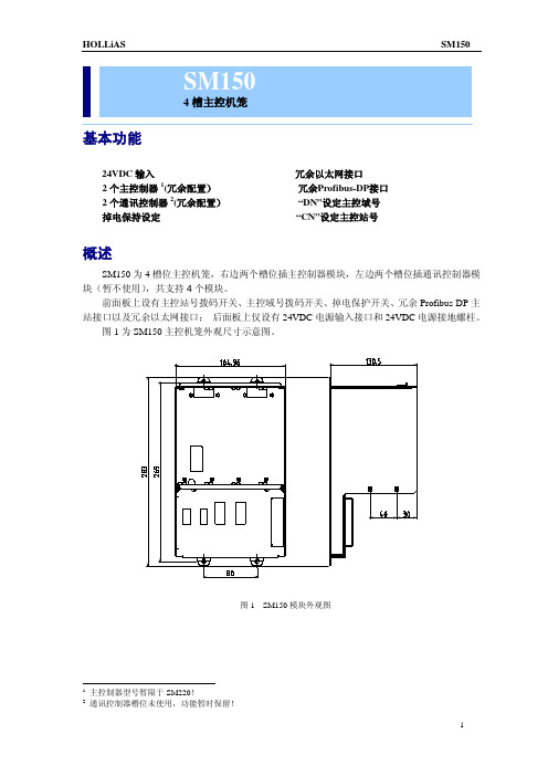
3 通讯控制器槽位未使用,功能暂时保留! 6
HollySys
HollySys
HollySys
HollySys
HollySys
HollySys
HollySys
HollySys
HollySys
HollySys
HollySys
HollySys
HollySys
DP DP A网 B网
NM910
NM910
NM610
NM610
NM610
NM610
NM610
拨码开关“DN”的第 7 位为主控制器掉电保护功能的设定开关;拨码开关“DN”的第 6 位、 第 8 位无连接,设定无效。
主控域号=20×K1+21×K2+22×K3+23×K4+24×K5
(其中 Ki=0 (i=1~5)表示第 i 位拨码的二进制数值)
例如:7 号域的拨码开关从高位到低位依次设定为“00111”,对应的十进制数值 7 就是主控 单元的域号,如图 4 所示。
以太网 以太网
1
2
直流配电
NULL
NULL
SM220
SM220
冗余24/48V输出
查询电源 输出
SNET1
B机 B
SNET2
SNET1
主控机笼 A A机 SNET2
DP DP A网 B网
HollySys
HollySys
HollySys
HollySys
HollySys
HollySys
HollySys
HollySys
终端匹配电阻
SM150 主控机笼内置,且固定连通 DP 总线终端匹配电阻,因此只须在总线链路末端的 I/O 机笼上才接通终端匹配电阻,用于吸收信号的反射和回波,位于总线链路中间的其他机笼则禁 止接通终端匹配电阻。
双笼电梯型使用说明(DOCX页)
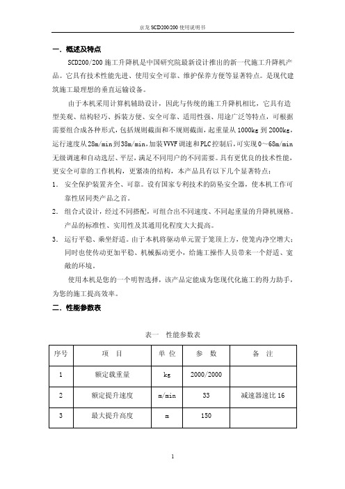
一.概述及特点SCD200/200施工升降机是中国研究院最新设计推出的新一代施工升降机产品。
它具有技术性能先进、使用安全可靠、维护保养方便等显著特点。
是现代建筑施工最理想的垂直运输设备。
由于本机采用计算机辅助设计,因此与传统的施工升降机相比,它具有造型美观、结构轻巧、拆装方便、安全可靠、适用性强、用途广泛等特点,可根据需要组合成各种形式,包括规则截面和不规则截面,起重量从1000kg到2000kg,运行速度从28m/min到38m/min,加装VVVF调速和PLC控制后,可实现0~68m/min 无级调速和自动选层、平层,满足不同用户的不同需要。
具有更优良的技术性能,更安全可靠的工作机构,更紧凑的结构,本产品具有以下几个显著特点:1.安全保护装置齐全、可靠。
设有国家专利技术的防坠安全器,使本机工作可靠性居同类产品之首。
2.组合式设计,经过不同搭配,可组合出不同速度、不同起重量的升降机规格。
产品的标准性、实用性及其通用化程度大大提高。
3.运行平稳、乘坐舒适。
由于本机将驱动单元置于笼顶上方,使笼内净空增大;同时也使传动更加平稳、机械振动更小,给施工操作人员带来一个舒适、宽敞的环境。
使用本机是您的一个明智选择,该产品定能成为您现代化施工的得力助手,为您的施工提高效率。
二.性能参数表表一性能参数表序号项目单位参数备注1 额定载重量kg 2000/20002 额定提升速度m/min 33 减速器速比163 最大提升高度m 1504 吊笼内空(长×宽)m×m 3×1.35 吊笼内部高度m 2.26 启动电流 A 2707 工作电流 A 708 电能耗量KVA 13×39 电机功率KW 11×3 JC=100%|JC=25%10 标准节质量kg 14011 整机自重t 20 H=150m12 安全器型号SAJ3.0-1.2三.构造原理简介本机主要包括以下几个部分:导轨架、驱动体、驱动单元、电气系统、安全器座板、防坠安全器、限位装置、上电气箱、吊笼、下电器箱、底架护栏、电缆卷筒、电缆导架、附着装置、电缆臂架、手动起重机、滑车系统、天轮等。
FC300操作说明书

" 快速设置 .................................................................. 36 " 参数列表 .................................................................. 38 " 参数选择 .................................................................. 39
! 安全说明和一般警告 ...................................................... 7
" 处理说明 .................................................................. 7 " 软件版本 .................................................................. 7 " 高压警告 .................................................................. 8 " 安全说明 .................................................................. 8 " 避免意外启动 .............................................................. 9 " FC 302 的安全停止 .......................................................... 9 " IT 主电源 ................................................................. 9
栏木机使用说明书

DTL型铁路道口电动栏木机安装使用说明书目 录第一节 概述第二节 结构原理第三节 电动栏木机的部件特点及技术要求第四节 包装及随机附件第五节 栏木机安装使用注意事项第六节 维修配件第七节 图纸声明:安装前请仔细阅读说明书本公司保留随时更改本说明书的权利,恕不另行通知。
第一节 概述1. 用途道口电动栏木机主要应用在铁路与公路的平交道口上,在列车接近道口时,阻挡公路上的行人和车辆通过,保证行车安全。
2. 主要技术指标·工作环境:环境温度-40℃~+70℃,相对湿度不大于90%(+25℃时)周围环境中无发生爆炸危险、足以腐蚀金属及破坏绝缘的有害气体或导电尘埃。
·技术特性:3. 安装尺寸基础预埋螺栓尺寸:300mm*300mm 4*Φ22mm栏杆中心距底脚基面高 800mm栏木机中心距栏杆顶端≤10米第二节 结构原理1. DTL型电动栏木机由装有电磁摩擦制动器的电动机、装有离合器结构的减速机、回路控制器、栏杆、平衡块、托架、箱体、底座等组成。
(图1)2. 传动原理:1)电动机轴上的齿轮带动减速机齿轮经三级减速使输出轴旋转,带动栏杆升降。
(图2)2)装在输出轴上的扇形齿轮旋转至0O和90O时被摇板限位。
同时输出轴上的小齿轮带动回路控制器中的齿轮轴使凸轮旋转,从而使接点接通或断开,达到使栏杆处于水平或垂直两个极限状态时电机停转的目的。
(图3)3. DTL型电动栏木机的回路控制器一般使用两组接点。
一是在栏杆上升至垂直位置,该接点接触(称为90O接点)。
另一是在栏杆下落至水平位置,该接点接触(称为0O接点)。
它们与控制箱内的升落杆继电器组成的功能如下:1)列车区段无车占用时栏杆在垂直位置,90O接点接触,升杆与落杆继电器在吸起状态,电磁摩擦制动器断电制动,使栏杆保持在垂直位置。
2)列车进入控制区段时自动或手动使继电器落下,电磁摩擦制动器得电解锁,使电动机旋转,栏杆开始落下至水平位置。
这时,0O接点接触,落杆继电器吸起,使电动机断电而停转,并使电磁摩擦制动器断电制动,保持栏杆在水平位置。
FM300操作说明书

1. 安全说明
1.安全说明
请检查此操作手册和产品类型是否匹配。 请查看此手册中包含的所有备注和说明。手册中包含了前期准备和 安装、操作及维护各个阶段需要查看的重要信息。因此技术人员以 及设备负责人或授权人员必须仔细阅读此操作说明。 请将此操作手册放置在操作现场便于取阅的地方。针对此操作手册 或者产品有任何不明白或疑惑的地方,请联系制造商。
• 避免阳光和紫外线的照射
• 存储的湿度必须是< 90%,无冷凝。
2.应用
2. 应用
FM300 是一款适用于工业应用的,用来在规格参数允许范围内监测露点的传感 器。这些规格参数可以在“技术参数”章节中找到。 FM300 能够测量以下数据:
• 压缩空气或工业气体的露点 • 压缩空气或工业气体的微水(PPM) 测量单位的出厂设置:露点°Ctd、微水 PPM。其他单位可以通过可选的显示 器或服务套装进行设置。 FM300 露点传感器不能用于爆炸领域。若在爆炸区域使用,请联系制造商。 FM300 露点传感器主要用于工业环境中的压缩空气系统。
1.安全说明
常规安全说明 • 爆炸区域内不允许使用该产品
• 请在准备阶段和安装使用过程中查看国家法规。 备注
• 不允许分解产品。
• 请使用扳手将产品安装妥当。 注意! 仪器故障会影响测量值! 产品必须正确安装并定期维护,否则将导致错误的测量数据, 从而导致错误的测量结果。
• 安装设备时请查看气体流向。气体流向标记在外壳上。
• 此传感器只能安装在室内使用!假如要安装在室外,必须避免太阳直晒和雨水 冲洗。 • 我们强烈建议不要将 FM300 长期安装在潮湿的环境中。这种潮湿环境通常存 在于压缩机出口。
7. 安装
在安装传感器之前
1
FM320 8槽主控机笼模块使用说明书
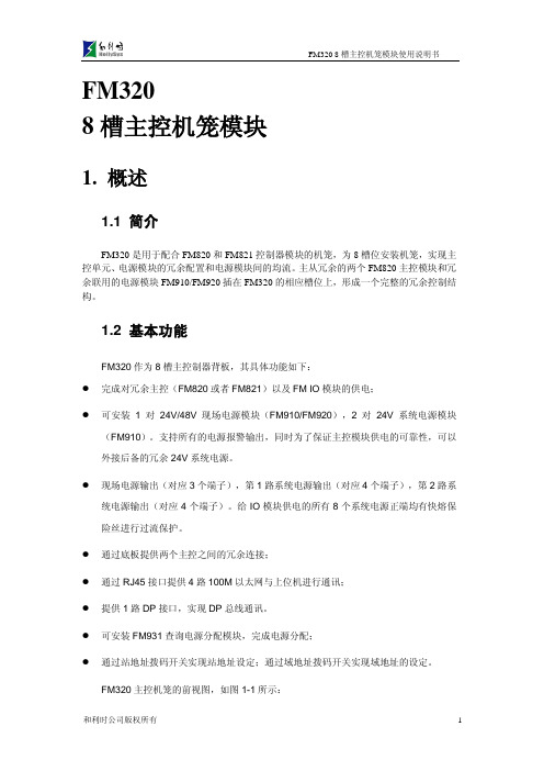
FM320 作为 8 槽主控制器背板,其具体功能如下: 完成对冗余主控(FM820 或者 FM821)以及 FM IO 模块的供电; 可安装 1 对 24V/48V 现场电源模块(FM910/FM920),2 对 24V 系统电源模块
(FM910)。支持所有的电源报警输出,同时为了保证主控模块供电的可靠性,可以 外接后备的冗余 24V 系统电源。 现场电源输出(对应 3 个端子),第 1 路系统电源输出(对应 4 个端子),第 2 路系 统电源输出(对应 4 个端子)。给 IO 模块供电的所有 8 个系统电源正端均有快熔保 险丝进行过流保护。 通过底板提供两个主控之间的冗余连接; 通过 RJ45 接口提供 4 路 100M 以太网与上位机进行通讯; 提供 1 路 DP 接口,实现 DP 总线通讯。 可安装 FM931 查询电源分配模块,完成电源分配; 通过站地址拨码开关实现站地址设定;通过域地址拨码开关实现域地址的设定。 FM320 主控机笼的前视图,如图 1-1 所示:
PE
图 2-4 电源模块部分的后盖板接线
4 个 5.08mm 间距 3 针插座与 3#、4#电源模块相连,提供第 2 路系统电源,每个插座对 应 1 个快熔保险丝。3 个 5.08mm 间距 3 针插座与 5#、6#现场电源相连,提供 48VDC/24VDC 查询电源输出。
第一路、第二路 220VAC 输入插座外接现场 220VAC 交流电源,“L1”、“L2”为火线 输入端,“N1”、“N2”为零线输入端,“E1”、“E2”应与左下角的机壳接地保护螺钉 “PE”相连。
24V+(1) GND(4)
第一路系统电源2
SNET1
SNET1
SNET2
SNET2
FC300系列操作手册

放电时间!
未打开变频器电源时,变频器直流回路的电容器可能仍有 电。为了避免出现电气事故,应断开交流主电源、所有永磁 电动机、所有远程直流回路电源,包括备份电池、UPS,以 及与其它变频器的直流回路连接。请等电容器完全放电后, 再执行维护或修理作业。等待时间详见放电时间表。如果 在切断电源后不等待规定的时间就执行维护或修理作业,将 可能导致死亡或严重伤害。
输出功率
• 为实现有效的操作和控制,输
入电源、内部处理、输出和电 动机电流都会受到监测
• 系统还会监测并执行用户界面
命令和外部命令
• 可以实现状态输出和控制
表 1.3 图 1.3 图例
6
MG33AM41 - VLT® 是 Danfoss 的注册商标
简介
VLT® AutomationDrive 操作 手册
表 1.2 图 1.2 的图例
11 继电器 2(04、05、06) 12 吊环 13 安装槽 14 接地线夹 (PE) 15 电缆应力消除/PE 接地 16 制动端子(-81、+82) 17 负载共享端子(直流总线)(-88、+89) 18 电动机输出端子 96 (U)、97 (V)、98 (W) 19 主电源输入端子 91 (L1)、92 (L2)、93 (L3)
2 安装
2.1 安装场址检查清单 2.2 变频器和电动机安装前检查清单 2.3 机械安装
2.3.1 冷却 2.3.2 起吊 2.3.3 安装 2.3.4 紧固力矩 2.4 电气安装 2.4.1 要求 2.4.2 接地要求 2.4.2.1 漏电电流 (>3.5 mA) 2.4.2.2 使用屏蔽电缆接地 2.4.3 电动机连接 2.4.4 交流主电源接线 2.4.5 控制线路 2.4.5.1 访问 2.4.5.2 控制端子类型 2.4.5.3 控制端子的接线 2.4.5.4 使用屏蔽型控制电缆 2.4.5.5 控制端子功能 2.4.5.6 跳线端子 12 和 27 2.4.5.7 端子 53 和 54 开关 2.4.5.8 机械制动控制 2.4.6 串行通讯 2.5 安全停止 2.5.1 端子 37 安全停止功能 2.5.2 安全停止试运行
FM820 FM系列主控制器模块使用说明书
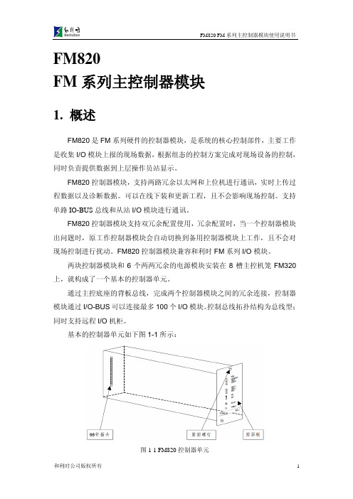
FM820FM系列主控制器模块1. 概述FM820是FM系列硬件的控制器模块,是系统的核心控制部件,主要工作是收集I/O模块上报的现场数据,根据组态的控制方案完成对现场设备的控制,同时负责提供数据到上层操作员站显示。
FM820控制器模块,支持两路冗余以太网和上位机进行通讯,实时上传过程数据以及诊断数据。
可以在线下装和更新工程,且不会影响现场控制。
支持单路IO-BUS总线和从站I/O模块进行通讯。
FM820控制器模块支持双冗余配置使用,冗余配置时,当一个控制器模块出问题时,原工作控制器模块会自动切换到备用控制器模块上工作,且不会对现场控制进行扰动。
FM820控制器模块兼容和利时FM系列I/O模块。
两块控制器模块和6个两两冗余的电源模块安装在8槽主控机笼FM320上,就构成了一个基本的控制器单元。
通过主控底座的背板总线,完成两个控制器模块之间的冗余连接,控制器模块通过I/O-BUS可以连接最多100个I/O模块。
控制总线拓扑结构为总线型;同时支持远程I/O机柜。
基本的控制器单元如下图1-1所示:图1-1 FM820控制器单元FM820主控模块为盒式插件结构,前面板有模块状态指示灯、掉电保护开关、复位按钮及电池仓旋钮。
后面板的96针插头实现与FM320 8槽主控机笼的连接,通讯接口、站地址、域地址、电源接口均位于FM320机笼的背板上。
2. 使用说明2.1.状态指示灯与前面板说明FM820主控制器前面板上有丰富的状态灯,现场实时显示电源、网络、通道的工作状态,为维护人员提供直观和快捷的故障提示。
表2-1 状态指示灯说明灯名称颜色状态含义RUN 绿亮正常运行灭停止运行STANDBY 黄亮主控单元为从灭主控单元为主ERROR 红亮主控故障或未完成初始化灭主控单元正常运行PROJECT 绿亮主控有工程闪工程下装或备份灭主控没有工程SYNC黄亮同步通路正常闪同步数据正常灭同步通路故障(单主控)SNET1 黄亮系统网1链接正常闪系统网1链接正常并处于数据交换灭系统网1故障SNET2 黄亮系统网2链接正常闪系统网2链接正常并处于数据交换灭系统网2故障CNET 黄亮控制网节点正常闪控制网节点正常且有数据交换灭控制网节点故障面板紧固螺钉状态指示灯掉电保护开关复位按钮可更换电池仓面板把手图2-1 FM820主控前面板图2.2.安装与固定主控单元采用“模块+机笼”组合的结构,安装在机柜中。
RF300大型环形天线用户手册说明书

Laplace Instruments LtdLAPLACE INSTRUMENTS LTDRF300Large Loop Antenna (Van Leen Loop)2 metre diameterMk II-AUSER MANUALVer 2.00 October 2011Serial number: XXXXDistributed by:Reliant EMC LLC3311 Lewis AveSignal Hill CA 90755408-916-5750This Page intentionally blankIndex1.0 Introduction2.0 Packing List3.0 Assembly4.0 Calibration loop5.0 Calibration6.0 OperationAppendixA. Calibration dataB. Latest changes to standardsCISPR15 & CISPR16.This Page intentionally blank1.0 IntroductionThe RF300 large loop antenna has been developed to meet the requirements of EN55015: 2006 + A2: 2009, section 9.9.1, which refers to CISPR16-1-4: 2007 + A1: 2008 section 4.6.1. This specifies the limits for magnetic field induced current for luminaires with lamp operating frequencies in excess of 100Hz.Construction of the RF300 is as detailed in annex C of EN55016. This antenna is fully compliant with the standard and details of the calibration factors are included in this manual. These antenna factors should be added to the results to obtain correct measurements that can be compared directly with the limits.Test setup and limits should be conducted as required by EN55015, section 4.4.The design of the RF300 is such that it can be readily erected and provide a rigid and stable configuration for accurate and repeatable measurements.A calibration loop (RF300C) is available as an option if on-site calibration is deemed necessary. The RF300C allows the calibration loop to be used on all three axes and rotated within each as required by the standards.Quantity Item2 Plates A2 Plates B4 Plates C8 Plates D3 Loop antennas (Blue)4 Corner posts4 Base extensions1 Central pillar4 Saddle Clips31 Grip screws (M10)31 Grip nuts (M10)8 M6 x 12 screws and nuts3 Loop transducers (current sensors)1 Switch Unit1 Short BNC—BNC cable, patch cable1 BNC—BNC cable (5m), output cable3 BNC—BNC cable (1.5m), loop leads1 10dB attenuator2 TiewrapsFigure 15Arrangement at top of loops. Use 2 tywraps in series for adequatelength.5.0 CalibrationThe calibration technique is fully described in CISPR16. It requires the use of a signal generator covering the range 9KHz to 30MHz with a50ohm output that is calibrated for 1v rms emf.See appendix AThe calibration data for each loop is virtually identical. The following details therefore apply to all three axes, although full data for each axis is given in the appendix.For reference, the ‘ideal’ curve is shown in graph 1. This is taken directly from EN55016, annex C, Figure C8.The antenna factor data for the RF300 are also given.This ‘antenna factor’ correction data effectively converts the output from the RF300 (measured in dBuV) directly to dBuA.The data can be used with any analyser or receiver capable of EMC measurements.The estimated measurement uncertainty is 3dB.For a detailed explanation of the calibration of the RF300 and discussion of changes to CISPR15 (EN55015) and CISPR16, see appendix BIf using the SA1002 or SA3000 analyser:The RF300 is listed under the normal Inputs menu. Just select this device and the software automatically applies the appropriate correction factors so that the trace reads correctly in dBuA and can be compared directly with the EN55015 limits.Further details are given in section 6.16.0 OperationDetails of the measurements and limits are given in EN55015, section 4.4. A copy of this should be consulted if performing compliance tests.The UUT should be mounted on a wooden frame or table in the centre of the antenna. The position is not critical.Connecting cables to the EUT should leave the volume enclosed by the loops in such a way as to be kept away from the loops to avoid capacitive coupling. See Fig C6 in CISPR16.Each axis (loop) should be measured in turn. Each should meet the requirements of the standard. The loops are individually selected by connecting the short patch lead to the appropriate input socket as shown in fig 11.6.1 Measurement with the SA1002 or SA3000 and EMCEngineer Windows software.1. Select the RF300 item under the input menu. The vertical scale will indicate units of dBuA. (If this item is not available, you need a later version of the software. Contact your supplier)2 Under the limits menu, select the EN55015 ......... 2m loop antenna limit line.3. Connect the switch unit to the analyser input.4. With the UUT switched off, check the background signal level. At frequencies below 1MHz, the background can be very strong. If strong signals do exist, check that the analyser is not in compression by changing the input attenuator setting on the analyser and comparing scans. Apart from the base line, the traces should overlay. If this happens then it is OK to use the analyser with that attenuator setting. If not, increase the attenuation and try again.5. If the background is strong, it is advisable to either find a ‘quieter’ location or screen the room.6. Switch the UUT on. Check the levels of signal over the background levels using the techniques used for conventional radiated testing as described in the user guide.The levels displayed are fully compensated for the RF300 characteristicsAPPENDIX ACALIBRATION DATA1. CISPR16 ‘ideal’ plot2. Calibration data.3. RF300 actual sensitivity plots and RF300correction plot (Antenna Factor)This Page intentionally blankThis Page intentionally blankThis Page intentionally blankAppendix BChanges to standards CISPR15 and CISPR16, 2009Technical Report Laplace Instruments Ltd January 2010 RF300 Large loop antenna, an analysis of changes to the standards These changes are due to the amendments to CISPR15 and CISPR16The latest versions are now …..CISPR15:2006 + A2:2009 andCISPR16-1-4:2007 + A1:2008The key changes related to LLAs are:1. Sections related to the construction and specification of LLAs are moved fromCISPR15 to CISPR16. Note that in the new CISPR15, the requirements for theLLA are referred to Section 4.7.1 in the new CISPR16, which does not exist! Itseems that the reference should be to Section 4.6.1. The same error is repeated in CISPR16 which again refers in Annex C to the non-existent section 4.7.2. The definition of the calibration data has been re-defined.PreviousCISPR15New CISPR16 Notes Significant changesAnnex B Annex C Description, construction andvalidation of LASBoth annexes combined into one.Annex CClause B1 Clause C1 Introduction Loop antenna named LAS (LoopAntenna SystemClause B2 Clause C2 Construction of LAS Additional requirements for cables andconnectors.Clause C3 Construction of loop Information previously included withdiagrams now included in text. Note lowR for inner conductor is required.Clause B3 ----- Positioning of the LAS Requirement for minimum distance tonearby objects,…… not included in newCISPR16Clause B4 Clause C4 Validation New definition for validation factor. (seebelow).Figure B1 Figure C1 General view NoneFigure B2 Figure C2 Position of slits NoneFigure C3 Construction of slits NoneFigure C5 Metal box for current probe NoneFigure B3 Figure C4 Example slit construction NoneFigure B4 Figure C8 Validation factor Converted from dBuA to dB(Ω). Seebelow.Figure C7 Positions of calibration loop NoneFigure C9 Construction of calibration loop NoneFigure C1 Figure C11 Sensitivity vs diameter NoneFigure C2 Figure C10 Conversion factors between loopcurrent and magnetic fieldstrength at a distance. Factors for magnetic field with electric field added. Factors for distance 30m removed.Note 1.The details of the LLA were given in Annex B of CISPR15. These are now transferred to Annex C of CISPR16. Most of the content has remained the same, but Table 1 summarises the changes.Note 2CISPR15 gave the verification data as a plot of loop current in dBuA vs frequency for the standard test signal (1V, open circuit voltage with a source impedance of50ohm). This seems to be a straightforward method, especially as the limits are quoted in dBuA, so it’s a direct correlation between the calibration loop and the limits.CISPR16 is essentially the same information, but presented differently. It specifies the relationship between the source voltage (1V, as specified above) and the output current in the loop as measured by the current probe. Note that the current probe has a transfer characteristic of 1V/A. The relationship between volts and current is ohms, hence the use of dB(ohms) as the ‘validation factor’.The result is therefore a conversion factor scaled in dB(Ω) to convert current to voltage,CISPR16 defines the validation factor dB(Ω) = 20*log(Vs/Ii) where Vs is the source voltage and Ii is the loop current.Vs = 1V = 1,000,000uVUnder ‘old’ CISPR15, for Ii @ 100KHz = 46dBuA = 200uASo the new CISPR16 value is 20*log(1000000/200) = 74 dB(Ω)andOld CISPR15 for Ii @ 30MHz = 29dBuA = 29uASo the new CISPR16 value is 20*log(1000000/29) = 91 dB(Ω)These calculations confirm the relationship between the CISPR15 plot and the CISPR16 validation factor.The plots in the standards assume a current probe with a 1V/A transfer function. Such probes are ‘active’ but provide a flat frequency response. The RF300 uses passive probes which have a non-flat frequency response. This is not important if the probe is ‘inside’ the calibration loop and has a linear transfer function with amplitude. These factors hold true for the probe that is used. So the RF300 antenna uses an antenna factor correction to produce a calibration that agrees with the validation factor. This antenna factor is supplied with each antenna, and is equivalent to the correction factors as supplied with all EMC antennas, test cells, LISNs and other types of transducer.Using the antenna factor data with the RF300 enables the output to be compared directly with the limits as specified in EN55015.LAPLACE INSTRUMENTS LTDDistributed by:Reliant EMC LLC3311 Lewis AveSignal Hill CA 90755408-916-5750。
MPCF300-6孔隙调节型纤维过滤器安装使用说明书.-1doc
关闭反洗水泵,关闭反洗进水阀、反洗排气阀,此时纤维丝处于旋紧状态。
如果长时间待机维丝纤处于放松状态。
五、PCF纤维过滤器使用注意事项
1).设定反冲洗压差(0.05~0.12MPa)时,不要设定过高,(压差设定过高会造成过滤水质恶化,水量减少,排管异常等);
2).气动阀、调节阀、采用对夹式蝶阀,止回阀采用对夹式气动阀。调节阀、止回阀的口径要与PCF过滤器进出水(气)管口口径相匹配。
PCF过滤器PORE CONTROL FLLTER(孔隙调节型纤维过滤器)的工作原理是:用微细且多束的柔软纤维丝,施以回转机具或压榨包等去压榨,使其孔隙变小,水中的悬浮物均被挡住留在过滤纤维丝外,经过滤后得到清洁的处理水。当过滤器内被截留的悬浮污物(杂质)增多,处理水量下降,压力达到设定值时,自动进入反冲洗过程,让过滤器的压榨机具放松,使过滤纤维的孔隙在舒张的状态下,用压缩空气和处理水反冲洗,将污物通过排放管排除,然后又自动进入过滤程序,从而实现去污存清的原理。
3、气缸的控制说明
为保证气缸运行顺畅,必须为气缸提供特殊的电磁阀和足够粗的压缩空气管,本设备MPCF-300,配备的电磁阀型号为:K25D-25,G1螺纹,配气管为Φ32,同时压缩空气管最好从主压缩管道直接引到电磁阀,且配气管为Φ32。以保证气缸的运行速度。
气缸的电磁阀控制按下条步序。
4、设备存放与保管
反冲洗1运行:
关闭原水泵和原水进水阀以及处理水出水阀。打开反洗排气阀、反洗排水阀、反洗进水阀和反洗进气阀,确认纤维丝处于放松状态,然后启动反洗水泵和罗茨风机,持续25秒后旋紧纤维丝5秒,再放松纤维丝25秒,共进行放松、旋紧过程4次。(原水水质不同反洗时间现场确定)
反冲洗2的运行:
保持上述状态,关闭反洗进气阀、罗茨风机、反洗排水阀,放松纤维丝,持续50秒。
FC300 操作说明书(MG33A143)

VLT® AutomationDrive FC 300
FC 300 操作說明書
目錄
如何閱讀操作說明 ........................................................ 3
認可 ...................................................................... 4 符號 ...................................................................... 5 縮寫 ...................................................................... 5
供透過 DeviceNet Fieldbus 控制、監控和規劃傳動裝置的必要資訊。 - VLT AutomationDrive FC 300 MCT 10 Operating Instructions (VLT AutomationDrive FC 300 MCT 10 作業說明) 提供在電
腦上安裝和使用軟體的資訊。 Danfoss Drives 技術文獻也可在 /drives 網站上找到。 認可
「疑難排解」的分頁符號。
FC 300 300 Operating Instructions (VLT AutomationDrive FC 300 作業說明) 提供啟動和運轉
傳動裝置的必要資訊。 - VLT AutomationDrive FC 300 Design Guide (VLT AutomationDrive FC 300 設計指南) 詳細說明關於傳動裝置及客戶
自动装卸笼系统操作规程(3篇)
第1篇一、概述自动装卸笼系统是现代物流领域中的重要设备,主要用于实现货物在仓库、装卸区等场所的自动化装卸作业。
本规程旨在规范自动装卸笼系统的操作流程,确保操作安全、高效、准确。
二、操作前的准备1. 人员培训:操作人员必须经过专业培训,了解自动装卸笼系统的结构、工作原理、操作方法和安全注意事项。
2. 设备检查:操作前应检查自动装卸笼系统各部件是否完好,包括链条、输送带、传感器、控制柜等。
3. 环境检查:确保操作区域环境整洁,无障碍物,地面平坦,无积水。
4. 安全设备:确保安全防护装置(如紧急停止按钮、防护栏等)完好有效。
三、操作步骤1. 启动系统:- 打开控制柜电源开关。
- 启动输送带电机,观察输送带是否正常运行。
- 检查传感器是否正常工作,确保系统能够准确检测货物位置。
2. 装载货物:- 将货物放置在输送带上,注意货物尺寸应符合笼筐规格。
- 检查货物是否平稳放置,避免偏载或超高超宽。
3. 启动提升系统:- 按下提升按钮,启动提升电机,观察笼筐是否平稳上升。
- 检查笼筐是否与输送带保持同步运行。
4. 输送货物:- 确保笼筐在输送带上平稳运行,无卡滞现象。
- 检查输送带速度是否适中,避免过快或过慢。
5. 卸载货物:- 到达指定卸载区域后,按下卸载按钮,启动卸载机构。
- 检查货物是否顺利卸载,避免损坏。
6. 停止系统:- 按下停止按钮,关闭输送带电机和提升电机。
- 关闭控制柜电源开关。
四、操作注意事项1. 严禁超载:装载货物时,严禁超过笼筐设计载重。
2. 禁止违规操作:操作过程中,严禁触摸运动部件,避免发生意外伤害。
3. 紧急情况处理:- 如遇紧急情况,立即按下紧急停止按钮,切断电源。
- 如发生火灾或电气故障,立即报警并切断电源。
4. 维护保养:- 定期检查设备各部件,及时更换磨损件。
- 保持设备清洁,定期润滑。
五、操作记录操作人员应详细记录每次操作的时间、货物种类、数量、设备状态等信息,以便于设备维护和故障排查。
- 1、下载文档前请自行甄别文档内容的完整性,平台不提供额外的编辑、内容补充、找答案等附加服务。
- 2、"仅部分预览"的文档,不可在线预览部分如存在完整性等问题,可反馈申请退款(可完整预览的文档不适用该条件!)。
- 3、如文档侵犯您的权益,请联系客服反馈,我们会尽快为您处理(人工客服工作时间:9:00-18:30)。
输出
L1 第一路 N1 220VAC E1 输入
220VAC 220VAC
L2 风机电源 N2 220VAC
输出
L2 第二路 N2 220VAC E2 输入
L1 备用电源 N1 220VAC
输出
L1 第一路 N1 220VAC E1 输入
去机柜保护地
(a)单路交流供电
HollySys 3
FM300 机笼单元
在需要将查询电源分配为多路的情况下,FM300 背板上最多可以安装两块 FM930 查询电
2.1.1 主控单元部分
2 HollySys
FM300 机笼单元
ON ON
B机站号
A机站号
B机的DP通信、 电源插座
24V+ GND DP+ DP-
B机DP网
24V+ GND DP+ DP-
A机DP网
A机的DP通信、 电源插座
B机的两个RJ45以态网接口
SNET1 SNET2
SNET1 SNET2
A机的两个RJ45以态网接口
B机系统网2.2 交流输入接线说明
只有一路交流输入时,接法如图 2-4(a)所示;两路交流输入时,接法如图 2-4(b) 所示。
2.3 拨码开关的设置
如图 2-2,从下到上依次为第 1~6 位,用于设置主控单元站号,ON 为 0,OFF 为 1.换算 方法如下:
站号=20×K1+21×K2+22×K3+23×K4+24×K5+25×K6 其中,Ki=0 表示第 i 位的开关拨到 ON 位置,Ki=1 表示第 i 位的开关拨到 OFF 位置 (i=1~6)。对于双机系统,两个拨码开关要设成一致。对于单机系统,原则上只设置插有 FM801 一侧的拨码开关,但是为了方便硬件配置的更改,建议无论单机系统或者双机系统,拨码开 关均设成一致。 例:图 2-5 所示为 10 号现场控制站主控单元拨码开关的设置:
风机电源输出和备用电源输出都是 220VAC 电源输出端口,可为现场其他设备供电。
1#2#电源报警输出对应 1#、2#电源模块,3#4#电源报警输出对应 3#、4#电源模块(电源 编号见图 1-1),其中“DOn+”、“DOn-” (n=1~4)为第 n 号电源模块的报警输出正负端。 当电源正常工作时,“DOn+”、“DOn-”端接通;当电源发生故障时,“DOn+”、“DOn-” 端断开。
现场电源
48V/24V+ FGND FGND
DO3+ DO3- DO4+ DO4-
DO1+ DO1- DO2+ DO2-
3#4#电源 报警
1#2#电源 报警
L1 备用电源 N1 220VAC
输出
L1 第一路 N1 220VAC E1 输入
主控单元部分
24V+
24V+
GND
GND
GND
GND
FM300
3#4#电源 报警
1#2#电源 报警
24V+ GND GND
24V+ GND GND
系统电源
L1 备用电源
N1
220VAC 输出
L1 第一路
N1 220VAC 输入
E1
图 2-3 电源部分
220VAC
L2 风机电源 N2 220VAC
输出
L2 第二路 N2 220VAC E2 输入
2.使用说明 ............................................................. 2 2.1 接线端子定义.......................................................................................................... 2 2.2 交流输入接线说明 ................................................................................................. 5 2.3 拨码开关的设置 ...................................................................................................... 5 2.4 安装与固定............................................................................................................. 5
1.2 组成
如图 1-1 所示,一个 FM300 机笼中有 6 个槽位,每个槽位有一个 64 针插座,连接相应 的模块。最左边两个槽插入两块主从冗余主控单元模块 FM801。剩下四个槽位插入电源模块, 依次定义为 1#电源、2#电源、3#电源、4#电源,其中 1#2#电源是系统电源,提供 24VDC, 选用 FM910;3#4#电源是查询电源,提供 48VDC/24VDC,根据不同的查询电压要求,选用 FM920 或 FM910。
源分配模块。FM930 的电源输入由 FM300 背板上的现场电源插座提供。
L2 风机电源 220VAC
N2 输出
L2 第二路 N2 220VAC
输入
E2
48V/24V+ FGND FGND
现场电源
48V/24V+ FGND FGND
DO3+ DO3- DO4+ DO4-
DO1+ DO1- DO2+ DO2-
3.技术指标 ............................................................. 6 4.相关产品 ............................................................. 6
HollySys
步骤二:将螺钉插入 FM300 两侧机械固定构件上的螺孔中,固定 FM300。
注:拆卸方法同上相反,先进行步骤二,再进行步骤一。
3.技术指标
尺 寸 长×宽×高 = 426mm×310mm×177mm(4U 高 19″标准机笼) 安装方式 螺钉紧固 环境温度 0℃~45℃。 工作湿度 5%~95%相对湿度 ,不凝结
2.1.2 电源模块部分
如图 2-3 所示,两个 3 针系统电源插座与 1#2#电源模块相连,提供 24VDC 工作电源输 出;两个 3 针现场电源插座与 3#4#电源模块相连,提供 48VDC/24VDC 查询电源输出。
第一路、第二路 220VAC 输入插座外接现场 220V 交流电源,“L1”、“L2”为火线输入 端,“N1”、“N2”为零线输入端,“E1”、“E2”为交流接地保护端。接线时,“E1”、 “E2”应与左下角的机壳接地保护螺钉 连接,如图 2-4 所示。
12 3 4 5 6 12 3 4 5 6
ON ON
系统电源
B机站号
24V+ GND DP+ DP- B机DP网
SNET1
A机站号
24V+ GND DP+ DP- A机DP网
SNET1
SNET2 B机系统网
SNET2 A机系统网
图 2-1 FM300 后视图
2.1 接线端子定义
如图 2-1 所示,FM300 背板上的接线端子分为两部分:右侧为主控单元的接线端,左侧 为电源模块的接线端。
硬件产品用户手册
FM300
机笼单元
北京和利时系统工程股份有限公司
8/5/2003
在未得到北京和利时系统工程股份有限公司书面明确许可的情况下,无论出于什
去机柜保护地
(b)双路交流供电
图 2-4 交流输入接线方法
4 HollySys
FM300 机笼单元
主控单元
FM300
1#
2#
3#
4#
系统电源
查询电源
紧固螺孔 机械固定构件 64针 插 座
图 1-1 FM300 前视图
FM300 的背板上有通信端口、电源输出端口、电源报警输出端口、220VAC 输入端口、站 号拨码开关等。
HollySys 1
ON
OFF
ON
OFF
=0
=1
=0
=1
ON
12 3 4 5 6
ON
12 3 4 5 6
10号站A机拨码开关设置
10号站B机拨码开关设置
图 2-5 拨码开关设置示意图
注:对拨码开关的操作应该在相应主控单元断电情况下进行。
2.4 安装与固定
步骤一:把 FM300 插入现场控制站机柜上部的支架中。
目 录
1.基本说明 ............................................................. 1 1.1 简介.......................................................................................................................... 1 1.2 组成.......................................................................................................................... 1
如图 2-2 所示,右侧部分与主控单元模块相连,两个 6 位拨码开关,分别用来设定冗余 主控单元的站地址;两个 4 针插座,是主控单元的系统电源和 DP 通讯的输出接口;四个 RJ45 插座,是主控单元的系统网输出接口。
FM300