纸币器BV20中文技术手册
BTA20-600BWRG中文资料
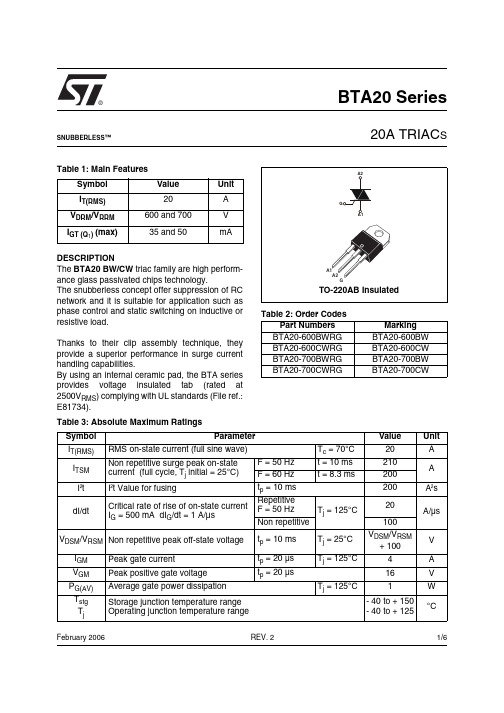
®1/6Table 1: Main FeaturesDESCRIPTIONThe BTA20 BW/CW triac family are high perform-ance glass passivated chips technology.The snubberless concept offer suppression of RC network and it is suitable for application such as phase control and static switching on inductive or resistive load.Thanks to their clip assembly technique, they provide a superior performance in surge current handling capabilities.By using an internal ceramic pad, the BTA series provides voltage insulated tab (rated at 2500V RMS ) complying with UL standards (File ref.:E81734).Symbol Value Unit I T(RMS)20A V DRM /V RRM 600 and 700V I GT (Q 1) (max)35 and 50mABTA20 Series20A TRIAC SREV. 2February 2006SNUBBERLESS™Table 2: Order CodesPart Numbers Marking BTA20-600BWRG BTA20-600BW BTA20-600CWRG BTA20-600CW BTA20-700BWRG BTA20-700BW BTA20-700CWRGBTA20-700CWTable 3: Absolute Maximum Ratings Symbol ParameterValueUnit I T(RMS)RMS on-state current (full sine wave)T c = 70°C20A I TSM Non repetitive surge peak on-state current (full cycle, T j initial = 25°C) F = 50 Hz t = 10 ms 210A F = 60 Hz t = 8.3 ms200I ²t I ²t Value for fusingt p = 10 ms200A ²s dI/dtCritical rate of rise of on-state current I G = 500 mA dI G /dt = 1 A/µsRepetitiveF = 50 HzT j = 125°C20A/µs Non repetitive100V DSM /V RSM Non repetitive peak off-state voltaget p = 10 ms T j = 25°C V DSM /V RSM + 100V I GM Peak gate current t p = 20 µs T j = 125°C4A V GM Peak positive gate voltage t p = 20 µs16V P G(AV)Average gate power dissipation T j = 125°C1W T stg T jStorage junction temperature range Operating junction temperature range- 40 to + 150- 40 to + 125°CBTA20 Series2/6Tables 4: Electrical Characteristics (T j = 25°C, unless otherwise specified)Table 5: Static Characteristics Table 6: Thermal resistance Symbol Test ConditionsQuadrant BTA20Unit BW CW I GT (1)V D = 12 V R L = 33 ΩALL MIN.21mA MAX.5035V GT ALL MAX. 1.5V V GD V D = V DRM R L = 3.3 k Ω T j = 125°C ALLMIN.0.2V I H (2)I T = 500 mA gate openMAX.7550mAI LI G = 1.2 I GTI - IIITYP.50-mAII 90-I - II - IIIMAX.-80dV/dt (2)V D = 67 %V DRM gate openT j = 125°C TYP.750500V/µs MIN.500250(dV/dt)c (2)(dI/dt)c = 20 A/msT j = 125°CTYP.3622V/µs MIN.1811Symbol Test ConditionsValue Unit V TM (2)I TM = 28 A t p = 380 µs T j = 25°C MAX. 1.70V I DRM I RRMV DRM = V RRMT j = 25°C MAX.10µA T j = 125°C3mANote 1: minimum I GT is guaranted at 5% of I GT max.Note 2: for both polarities of A2 referenced to A1.Symbol ParameterValue Unit R th(j-c)Junction to case (AC) 2.1°C/W R th(j-c)Junction to case (DC) 2.8R th(j-a)Junction to ambient60°C/WBTA20 Series3/6Figure 1: Maximum power dissipation versus RMS on-state current (full cycle)Figure 2: Correlation between maximum RMS power dissipation and maximum allowable temperatures (Tamb and Tcase) for different thermal resistances heatsink + contactFigure 3: RMS on-state current versus case temperature (full cycle)Figure 4: Relative variation of thermal impedance versus pulse durationFigure 5: On-state characteristics (maximum values)Figure 6: Non repetitive surge peak on-state current versus number of cyclesBTA20 Series4/6Figure 9: Ordering Information SchemeTable 7: Product SelectorFigure 7: Non-repetitive surge peak on-state current for a sinusoidal pulse with width t p < 10 ms and corresponding value of I 2tFigure 8: Relative variation of gate trigger current and holding current versus junction temperaturePart Numbers Voltage (xxx)Sensitivity Type Package 600 V 700 V BTA20-xxxBWRG X X 50 mA SnubberlessTO-220AB Ins.BTA20-xxxCWRGXX35 mABTA20 Series5/6Figure 10: TO-220AB Insulated Package Mechanical DataTable 8: Ordering InformationOrdering type Marking PackageWeightBase qtyDelivery modeBTA20-600BWRG BTA20-600BW TO-220AB Ins.2.3 g50TubeBTA20-600CWRG BTA20-600CW BTA20-700BWRG BTA20-700BW BTA20-700CWRGBTA20-700CWTable 9: Revision HistoryDate Revision Description of ChangesSep-20011A First issue.08-Feb-20062TO-220AB Ins. delivery mode changed from bulk to tube.BTA20 SeriesInformation furnished is believed to be accurate and reliable. However, STMicroelectronics assumes no responsibility for the consequences of use of such information nor for any infringement of patents or other rights of third parties which may result from its use. No license is granted by implication or otherwise under any patent or patent rights of STMicroelectronics. Specifications mentioned in this publication are subject to change without notice. This publication supersedes and replaces all information previously supplied. STMicroelectronics products are not authorized for use as critical components in life support devices or systems without express written approval of STMicroelectronics.The ST logo is a registered trademark of STMicroelectronics.All other names are the property of their respective owners© 2006 STMicroelectronics - All rights reservedSTMicroelectronics group of companiesAustralia - Belgium - Brazil - Canada - China - Czech Republic - Finland - France - Germany - Hong Kong - India - Israel - Italy - Japan - Malaysia - Malta - Morocco - Singapore - Spain - Sweden - Switzerland - United Kingdom - United States of America6/6。
最新人教版一年级下册语文句子专项基础练习及答案

最新人教版一年级下册语文句子专项基础练习及答案一、按要求写句子。
1.青蛙为什么没参加?(仿写句子)_______为什么________?2.弯弯的月儿像小船。
(写比喻句)________像_________。
3.连词成句。
(只写序号)①小丽②我③好④和⑤朋友⑥是_________________________。
①盼着②自己③快点儿④我⑤长大__________________________。
①花②真③花园里④呀⑤好看⑥的__________________________!二、照样子,写句子。
1.池塘里有一只青蛙。
____有_______。
2.弯弯的月亮像小船。
______像________。
3.我会整理书包。
我会__________。
4.小松鼠从树上跳下来。
____从__________。
三、照样子写句子。
1.例:小猫爱吃鱼。
兔子爱吃_______。
________爱吃________。
________爱吃________。
2.例:你真是个又聪明又勇敢的小家伙!妈妈是个又____又______的人。
____又_____又_______。
____又_____又_______。
3.例:游泳和跑步都是我喜欢的运动。
__________都爱读书。
__________都__________。
四、照样子,把下列句子补充完整。
①冬天,雪花从天上飘下来。
________飘________。
②老牛甩着长长的尾巴慢慢地走着。
________甩________。
③他今天到底来不来呢?________到底________?五、照样子,把词语放在句子中合适的位置。
例:天空上飘着白云。
(蓝蓝的)蓝蓝的天空上飘着白云。
(1)小狗吐出舌头。
(可爱的)_____________________________(2)沿着小路,就能走到公园。
(弯弯的)_____________________________(3)很多个小朋友做游戏。
MX-RB20_部品手册
[V] VHPSG2A141+-1
[X] XBPS730P06KS0 XBPS730P06KS0 XBPS740P08KS0 XEBS730P08000 XEBS730P08000 XEBS740P10000 XEBS740P10000
No.
3 PMAGT0146FCZZ
4 XHBS740P08000
5 XEBS740P10000
6 PSHEZ6610FCZZ
价格等级 部品等级
C
C
AD
C
AA
C
AA
C
C
右定位板 本体更换盖板 磁吸 螺钉 (4×8) 螺钉 (4×10) 右定位板贴片
中文名称
–9–
5 附属品
1
6 5
4
2 3
SHC02124
19 NBLTH0635FCZZ
20 NBLTH0634FCZZ
21 NPLYZ0453FCZZ
22 PSHEZ5394FCZ2
23 NPLYZ0567FCZZ
24 NPLYZ0437FCZZ
25 XRESP50-06000
26 NBRGP0884FCZZ
27 LPINS0133FCZZ
28 XEBS740P10000
– 11 –
No.
价格等级 部品等级
4-6
AA
C
5-5
AA
C
4-1
C
2-31
AA
C
1-14
AA
C
5-4
AA
C
2-25
AA
C
3-8
AA
C
捆钞机操作说明

操作说明2000A /2002/2002B一、开机打开电源,蜂鸣器鸣叫500ms,显示面板上六个发光二极管全部点亮,表示机器处于预热阶段,时间为二分钟。
二分钟以后,显示面板上六个指示灯全灭,此时为自动状态,按下“工作/暂停”按键进入自动工作。
自动工作时,打完直带后蜂鸣器鸣叫,六个指示灯闪烁,表示处于待捆状态,此时将币取出后重新放入进行第一道横带捆扎,捆扎完毕后同样将币取出重新放入进行第二道横带捆扎。
按一下“自动/手动”键,“自动/手动”指示灯点亮,进入手动状态,此时按下显示面板上的各功能键将执行相应的工作。
再按一下“自动/手动”键,“自动/手动”指示灯熄灭,进入到自动状态。
机器在每次开机后将控制交叉点烫合的小电机进行3s的复位,使其退回到初始位置。
正常工作时每执行一个环节,相应的指示灯会点亮,以便于直观的了解其工作过程,工作过程中若有故障,电脑将做出判断是哪个工作环节的问题,并通过蜂鸣器鸣叫和相应的指示灯闪烁给予提示,以便查找故障原因,解决问题。
二、测试“测试”状态时,显示板上温度窗口为安全保护测试显示,可遮挡保护装置相应的发射、接收管,其对应的显示会熄灭,遮挡各位置光耦显示面板上相应指示灯会变化;遮挡中心光眼、侧光眼,显示面板上的相应指示灯也会变化。
注:拨动电脑上的“工作/测试”小开关,可实现“工作/测试”的切换,正常工作时应在“工作”位置上。
三、设置1、温度设置:按一下显示板上“升温”或“降温”按键,温度窗口的显示发光二极管排就会相应增加或减小1格。
其中最小为1格,最大为8格。
2、带长设置:按住显示板上进带按键,接通电源,此时进带指示灯点亮,显示板上发光二极管排显示的为带头长度,带头长度最小为1格,最大为8格,每格代表1㎝,用升温和降温键来调整带头长度,每按一次升温或降温键发光二极管排增加或减少1格,相应带头长度增加或减小1㎝,关机后数据自动保存。
3、单道/三道捆扎设置:按住显示板手动键不放,接通电源,手动指示灯不亮,为单道捆扎,手动指示灯点亮为三道捆扎。
JCB Access电动剪刀快速入门指南说明书

Quick Start Guide JCB AccessElectric Scissors1Operation Transporting the MachineAX – X axis distance Y – Y axis distanceourmeterlatform Raise / Lower Toggle Switchmergency Stopround Controls / Off / Platform Controls Key Switch Please see operator manual for full details./ R Steeringrigger Switch to enable operation attery Level / Fault Code Display latform / Drive Mode Buttonspeed Selectmergency Stoprake Release Lockrake Release PumpHow to Release BrakesEnsure machine can be controlled before releasing brakesPush in brake release lockPump brake release until feels solidCaution – machine is now un-brakedTo reapply pull the brake release lock back out or operate any control on the joystick4Switch Key Left Toggle SwitchTurn the key switch left to enable the ground controls. Use the toggle switch to raise or lower the platform as required.Note: If the platform raise/lower fails to operate, ensure the key switch is in the correct position and all of the emergency stops have been pulled to release.457Trigger & JoystickCradle Release Mode SelectOperate Machine Pull the trigger on the back of the joystick to enable operation.The cradle can be released from the platform by removing the bolt.If CH is shown on the platform controller, the key switch is in the wrong position. The switch must be on platform controls to use them. The machine will Choose from either lift/lower or drive mode. Do not attempt to operate prior to charge status being shown.Pressure SensorsPothole Protection SwitchLimit SwitchesOnly use the original charger installed to the machine with the original batteries. Charge the battery in a well ventilated place. Use an appropriate grounded industrial power supply with correct AC (alternating current) input voltage to charge.If at any time a fault occurs when charging, three battery charge LEDs will blink at the same time. Refer to the operators handbook immediately.AC harge Point C harger Viewing WindowThe flashing LED indicates the charge level. When all three LEDs are solid, the machine is fully charged.Code Description Reaction Instructions 01System intialisation fault Disables all motion Restart the machine 02System communication fault Disables all motion Restart the machine 03Invalid option setting fault Disables all motion Restart the machine 04Load sensing data faultWarning only Contact the dealer 12Chassis up or down switch ON at power-up faultDisable chassis control Contact the dealer 18Pothole guard fault Check pothole protection 31Pressure sensor 1 fault 32Angle sensor fault 36Limp mode42Platform left turn switch ON atpower-up message 43Platform right turn switch on atpower-up message 46Platform joystick enable switch on atpower-up fault 47Platform joystick not in neutral at power-upDiagnostic codes are shown on both the platform controller and through a viewing window on the hydraulic tray door.JCB Sales Limited, Rocester, Staffordshire, United Kingdom ST14 5JP Tel:+441889590312Email:***************** Download the very latest information on this product range at: All rights reserved. No part of this publication may be reproduced, stored in a retrieval system, or transmitted in any form or by any other means, electronic, mechanical, photocopying or otherwise, without prior permission from JCB Sales. All references in this publication to operating weights, sizes, capacities and other performance measurements are provided for guidance only and may vary dependant upon the exact specification of the machine. They should not therefore be relied upon in relation to suitability for a particular application.Guidance and advice should always be sought from your JCB Dealer’. JCB reserves the right to change specifications without notice. Illustrations and specifications shown mayinclude optional equipment and accessories.9818/3000。
IMC02R 欧元 英镑伪币检测器用户手册说明书

Munbyn,More choice for your growing businessIMC02R Counterfeit DetectorUser ManualVersion 1.01Version 1.01Contents1.0. Unpack and Installation122333445681.0. Unpack and Installation 3.0.Technical Parameters1.1. Packing List1.2. Installation Instructions 2.1. Display Appearance 2.2. Turn On/Off the Machine 2.3. B utton Functions 2.3.1 Advance 2.3.2 Return2.4. Inserting the Banknote Correctly 2.5. EUR/GBP Currency Detecting2.6. Inaccurate Detection of Currency Detector 2.0.Operating InstructionsVersion 1.01IMC02R Counterfeit Detector User Manual Page 1 of 9When you receive the package, open and check the packing list in the package.1.1. Packing ListItem NamePicture Quantity (pcs)DescriptionCounterfeit Detector Battery Power Adapter User ManualBill Counterfeit Detector11.1V 500mAh rechargeable battery Power Adaptor1111Table-1 Packing ListVersion 1.01IMC02R Counterfeit Detector User Manual Page 3 of 9Version 1.01IMC02R Counterfeit Detector User ManualPage 2 of 9Turn on the IMC02R by switch the power switch button to on, the screen will light up and the machine will start self-testing. If the self-test is successful, all of the screen lights will be on.Turn off the IMC02R by switch the power switch to off. When the screen lights off, it means the machine has been turned off successfully.Figure 2-2 IMC02R Power Interface2.2. Turn On/Off the Machine2.3. Button Functions 2.0. Operating InstructionsFigure 2-1 IMC02R Display Appearance2.1. Display AppearanceDC Power : Connect the power adapter to a 110V or 220V outlet, then connect the terminal to the machine’s DC12V input socket.Lithium Battery: When the battery was fully charged, the machine can work without power adapter.1.2. Power SupplyBanknote DirectionIndicatorBanknote Direction:AdvanceBanknote Direction:ReturnBanknote Detecting Result:Pass or FailPower switchThe banknote exit direction, advance.2.3.1. AdvanceVersion 1.01IMC02R Counterfeit Detector User ManualPage 5 of 9Version 1.01IMC02R Counterfeit Detector User ManualPage 4 of 9As shown in the following figures, please remove the banknote feeding limit block to adjust the banknote with bigger size.2.5. EUR/GBP Currency DetectingFigure 2-3 Banknote Insertion2.4. Inserting the Banknote CorrectlyFigure 2-4 Banknote InsertionThe banknote exit direction, return.As shown in the following pictures, please insert the banknotes in the left side. If a banknote was incorrectly inserted, the IMC02R may refuse it and alert.2.3.2.ReturnThe banknote feedinglimit blockFigure 2-5 EUR Banknote DetectingFigure 2-6 Bill Damaged Ways 2.6. Inaccurate Detection of Currency DetectorThere are several conditions to affect the accuracy of the currency detector.1) The bill size is out of the range according to IMC02R specification.2) The banknote is damaged with different ways such as lack of corner, tape, hole, tear and folded. As shownin Figure 2-6, it is not recommended to count this kind of bills.3) Other abnormal operation or there is unknown thing inside the IMC02R.If something inside the IMC02R,you need to open the front cover to check, and clean the internal sensors.Version 1.01IMC02R Counterfeit Detector User Manual Page 7 of 9 Version 1.01IMC02R Counterfeit Detector User Manual Page 6 of 9Scan the QR code for Facebookonline chat Contact usIf you meet any problem during using the IMC02R, please contact us.******************+86178****1067+1 403 477 19113.0. Technical ParametersCounterfeit Detection MG (Magnetic), IR (Infrared), UV (Ultraviolet) Error Detection Image, paper quality, size, thickness detection Available currencies USD, EURDisplay Direction, Detection Result IndicationButton Advance/ReturnInterface USB, software upgrade interfaceDetecting Speed<0.5 seconds/piecePower Consumption<10WPower Supply Battery AC 100V-240V 50-60Hz or DC 12V/1.0ARechargeable lithium battery 11.1V / 500 mAhCertifications CE, FCC, ROHSOperating Temperature0°C - 40°CStorage Temperature-20°C - 65°CT able 3-1 Technical ParameterVersion 1.01IMC02R Counterfeit Detector User Manual Page 9 of 9Version 1.01IMC02R Counterfeit Detector User Manual Page 8 of 9。
BVR2100中文
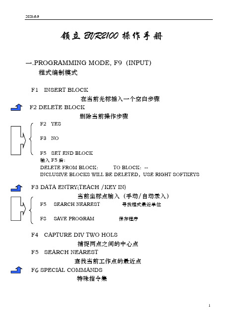
领立BVR2100操作手册一.PROGRAMMING MODE, F9(INPUT)程式编制模式F1 INSERT BLOCK在当前光标插入一个空白步骤F2 DELETE BLOCK删除当前操作步骤F2 YESF3 NOF5 SET END BLOCK输入F5后:DELETE FROM BLOCK:TO BLOCK:--INCLUSIVE BLOCKS WILL BE DELETED,USE RIGHT SOFTKEYS F3 DATA ENTRY(TEACH /KEY IN)当前坐标点输入(手动/自动录入)F5 SEARCH NEAREST 寻找程式最近单位F8 SAVE PROGRAM 保存程序F4 CAPTURE DIV TWO HOLS捕捉两点之间的中心点F5 SEARCH NEAREST查找当前工作点的最近点F6 SPECIAL COMMANDS特殊指令集F7 PROGRAMMING SERVICES辅助命令集F1 SET TOOL PARAMETER 设定各刀具参数F2 SUPT TOG LOCKED/UNLOCKED 输入操作权限密码F5 SET WZERO & ALIGN 设定及调整工作零点F1 SELECT WORK TABLE 1 选择工作台面1F2 SELECT WORK TABLE 2 选择工作台面2F4 MOVE TO WORK ZERO 主轴移动到该机器零点位置F5 TOGGLE TABLE 1 工作台1进/出控制F6 TOGGLE TABLE 2 工作台2进/出控制F7 TOGGLE VACUUM RIGHT/LEFT 吸尘器左/右转换控制F6 FLIP & EXP PROGRAM 图形方向转换及程式扩展F1 SWAP AXIS TOGGLE OFF 将钻孔方件的X,Y轴数据对换F2 MIRROR X TOGGLE OFF 沿X轴镜像该钻孔数据F3 MIRROR Y TOGGLE OFF 沿Y轴镜像该钻孔数据F8 PASSWORD NEW/CHANGE 修改操作权限密码F8 QUICK SAVE快速保存F9 F7 F1(刀具参数设定)TOOL DIA KRPM H—SET H--ACT LINKAGE SZ BZ INFEED PECK 刀具直径转速寿命孔目前使1,1.2,4 z z 每秒分步钻0) 分板机用次数分板机轴轴进刀1) 长度寿分次锣高底速度…命值刀的度度24) 寿命RETRACT ROUTE每秒退刀速度每秒切割速度二.FILE MANAGEMENT MODE, F10(AUXILIARY)档案管理模式F1 LIST PROGRAM显示当前工作目录下的文件清单F2 SAVE AS MARK 1 PROGRAM将当前钻孔数据另存为MARK 1程式F4 DELETE PROGRAM删除磁盘内的程式F5 LOAD MARK 1 PROGRAM调出内部MARK 1程式F7 CLEAR PROGRAM MEMORY删除当前内存所存储的数据F8 OTHER SERVICES其它功能F2 TOGGLE DATA DRIVE A/D 磁盘切换(D盘与A盘互换)F4 TRANSFER PROGRAMS 程式传输COPY DISK FROM TARGET TO DESTINATIONPRESS ANY KEY TO PROCEEDF5 CREATE FOLDER 建立文件目录F6 DELETE FOLDER 删除文件目录三. MANUAL AND DIAGNOSTIC MODE, F11(MANUAL)手动及诊测模式F1 SPINDLE OPERATION主轴控制命令集F2 SET SPINDLE SPEED设定主轴旋转速度F3 SPINDLE TOGGLE ON/OFF对主轴旋转的打开/关闭控制F2 CHANGE TOOL 刀具更换命令集F3 OFF SPINDLE 让主轴停止旋转F5 ASSIGN TOOL NO指定当前工作刀具号F6 SPINDLE UP 让主轴抬起F3 TOGGLE PARK TABLE操作台进/出控制F4 VACUUM TOGGLE吸尘器开/关控制F5 HOME MACHINE机器复位(X,Y,Z三轴归零)显示当前状态及校准F6 CALIBRATE AND STATUS1 OFF 右工作台面出2 OFF 左工作台面出3 OFF 紧急按钮松开4 OFF 桌面左启动按钮松开5 OFF 桌面右启动按钮松开6 OFF 左边门关7 OFF 右边门关8 ON 主轴马达存在ENTER TO RETURNF4 CALIBRATE JOYSTICK校准操作杆F1 DISPLAY JOYSTICK VALUE显示当前跳动参数OLD X VALUE :119 NEW VALUE:121OLD Y VALUE ;121 NEW VALUE:121 F5 UPADATE JOYSTICK VALUE 更新操作杆参数F8 MODIFY MACHINE DATA修改机器参数F1 CALIBERATA M /C 校准机器F4 UPDATE PITCH DATA 更新螺杆节距资料F5 UPDATE SYSTEM OS 更新作业系统F8 MAKE SYSTEM BACKUP DISK 制作系统备份盘四.AUTOMATIC OPERATION MODE, F12(AUTO)自动操作模式F1 RESET(START)开始设定开始孔与其它命令集F2 SET START AND OTHERF1 CUTTER COMPENSATION ON 锣板刀具半径补偿开/关F2 SPIN / VAC END O CYC ON 主轴/吸尘连动开关控制PLEASE CONFIRM CHANGE —Y—YES OR ENTER NO CHANGE F3 ALIGN ARTWK TOGGLE OFF 插图对准选择开/关F4 SET START BLOCK 程式单位选择/ 选孔钻孔ENTER NEW START BLOCK 1-6800:F5 SET START PATTERN 重复板跳位钻孔选择ENTER START PATTERN 1-99:F7 SET WORK ZERO 校位(以第一点为零位) JOG CAMERA TO FIRST HOLE LOCATIONPRESS ENTER WHEN DONEF8 CALIBRATE CAMERA OFFSET CCD校准注;先以CCD找点钻一孔/再让CCD在孔上用摇杆移动调整输入F8后:X:-61.49 Y:-8.51(原来的位置)移动到待调整的位置,敲回车X:--- Y:---此时软件会自动记录下当前调整的位置JOG CAMERA TO RIGHT LOCATION,PRESS ENTER WHEN DONE F3 TOGGLE PARK TABLE操作台进/出控制F4 Z MOTION OFF开始钻孔,Z轴上下开/关控制F5 RUN MODE CONTINUE/SINGLE STEP连续钻孔/单步模式选择F6 TOOL CHANGE MANUAL AUTO换刀方式手动/自动五.键盘功能键(1)多联片板的复制(拼板)P/B mark pattern begin定义块首(在复制多联片板时,首先要将复制的对象定义成一个块)P/E pattern end定义块尾(在复制多联片板时,首先要将复制的对象定义成一个块)P/R repeat array x: y: ---X,Y两个方向之间的间隔距离及需复制的数量(多联片复制)P/O repeat offset x: y;X,Y两个方向之间的间隔距离(单片复制)Eg:(多联片的复制)1. tool 12. mark pattern begin P/B 1.定义块首3. down x # y #4. down x # y#5. down x # y#6. down x # y#7. down x # y#8. down x # y#9. tool up10 pattern end P/E 2.定义块尾11 repeat array x: # y: # --- P/R 3.拼板间隔距离及数量进行完这三个步骤后,输入F9 F7 F6 F6(此步骤是将多联片板进行扩展复制),做完这个操作,此时你便可以查看程序是否复制成功。
纸币器BV20中文技术手册
BOP20操作说明

3.3 基本操作面板(BOP 20)控制电机BOP20(Basic Operator Panel 20)是一个带有背景灯显示和6个按键的基本操作面板。
BOP20可以直接安装在SINAMICS S120的控制单元(CU310 或CU320,固件版本2.4或以上)上进行操作。
3.3.1 BOP 20概述使用BOP20可以在调试的过程中实现对SINAMICS S120实现以下功能:•改变驱动对象,启动或停止驱动轴•实现参数的修改和显示•显示故障信息并复位故障在一个应用简单并使用SINAMICS S120的场合,使用BOP20是一个经济有效的选择。
图3.7 BOP20面板1. BOP20的LED 显示状态如下表所示:表3.2 BOP的LED显示状态2. BOP20的按键信息如下表所示:运行表3.3 BOP的按键信息3. BOP20的功能如下表所示:表3.4 BOP的功能表4. BOP20的相关参数:•对于控制单元➢r0000 BOP20运行显示➢p0003 BOP20访问等级➢p0004 BOP20参数显示过滤➢p0007 BOP20背景灯设置➢p0008 BOP20传动对象选择➢p0009 设备调试,参数过滤➢p0011 BOP20密码输入➢p0012 BOP20密码确认➢r0019 BOP20控制字➢p0977 保存所有参数•对于所有驱动对象➢p0005 BOP20运行显示选择➢p0006 BOP20运行显示模式➢p0013 BOP20用户定义参数➢p0971 保存传动对象参数•对于所有控制单元(如:servo,vector,infeed,TM31)➢p0010 调试参数过滤此外,通过BOP20实现的重要功能有:•工厂复位通过设置控制单元CU上的参数完成工厂复位➢p0009 = 30➢p0976 = 1•Copy RAM to ROM在CU上可以初始化所有参数,并保存在非易失性内存中(CF卡)➢按住P键3秒或➢p0009 = 0➢p0977 = 1•LED识别驱动器对象的主要组成部分(如,电机模块)可以通过参数p0124指数来识别。
MICROS Bump Bar MBB-10 和 MBB-20 用户手册说明书

MD0011-014Revision APage 1 of 15The MICROS Bump BarMBB-10 and MBB-20 User’s Guide This document describes the MBB features, shows how to adjust the speaker and LED from the keypad, as well as determine the firmware version and how to update if required. Other sections describe how to open the unit and configure the MBB circuit board configuration switches, and to service the unit.Introducing the MICROS Bump Bar (2)Adjusting the LED and Speaker from the Keypad (4)MBB Spare Parts (5)Opening the Micros Bump Bar (8)Specification Summary (13)MBB-10 Bracket Dimensional Drawing (14)MBB-20 Bracket Dimensional Drawing (15)MD0011-014Revision APage 2 of 15Introducing the MICROS Bump BarThe MBB-10 and MBB-20 are shown in the Figure below.Figure 1: The MBB-10 and MBB-20•USB Interface - 6ft cable standard.•Extruded aluminum case /w gasket sealed end caps for spill resistance to IP55 standards.•Magnetic keys offer improved tactile response over a membrane switch and millions of actuations. •Blue LED with adjustable brightness.•Internal speaker with adjustable volume.•The alpha and numeric keys can be reversed to allow the MBB interface cable to exit from the left or right.•Order notification through the speaker and LED. Refer to the PMA forspecific POS software support.MD0011-014Revision APage 3 of 15TemplateEach MBB is supplied with a standard template shown in the illustration. Mounting BracketsEach MBB is supplied with a quick release mounting bracket that can be mounted to a counter, wall surface or current third party KDS mounting hardware. The MBB-20 bracket hole locations are compatible with the QSR bumpbar for easy replacement. Refer to the MICROS Bump Bar PMA for more information about KDS mounting options.Adjustable LED and SpeakerThe MBB includes an internal speaker that serves two functions. The speaker sounds each time a key is pressed. If supported by the KDS software, the unit can also beep when an new order is received from the KDS controller. The keypress and order notification beep volume can be adjusted independently directly from the MBB keypad.Figure 2: MBB Speaker and LEDUSB Interface CableThe MBB-10 and MBB-20 both use a 6 ft. (1.8M) USB Interface Cable. If a longer interface cable is required, you can purchase and install an 11 foot (3.5M) cable, P/N 700503-070. Another option is the Belkin F3U130-16, a 16 ft. USB 1.1 cable extender. The MBB has been tested with two of the extender cables connected to the standard KDS controller. The extender cable (P/N700503-071) does not require an external power supply.MD0011-014Revision APage 4 of 15Adjusting the LED and Speaker from the KeypadThe LED brightness and Speaker volume can be adjusted directly from the keypad at any time. Figure 3, below summaries each adjustment.Figure 3: Adjusting the LED and Speaker volume from the Keypad Adjusting the LED BrightnessTo adjust the LED brightness, press and hold the [1] and [A] keys, then tap the[2] key to cycle through the Off, Normal, and Bright settings.Adjusting the Keypad SpeakerTo adjust the volume, press and hold the [1] and [A] keys, then tap the [B] key to cycle through the Off, Normal, and Loud speaker settings.Adjusting the Order Notification BeepTo adjust the order notification volume, press and hold the [1] and [A] keys then tap the [3] key to cycle through the Off, Normal, or Loud settings.Internal Configuration SwitchesThe MBB circuit board includes two switches that can be set to send lower or upper case characters, or reverse the location of the character and numeric keys for increased mounting flexibility. See Figure 10 for more information. To open the MBB and access the configuration switches, see page8.MD0011-014Revision APage 5 of 15MBB Spare PartsIn addition to a 3.5M USB Interface Cable, several other spare parts are available for the MBB-10 and MBB-20.USB Interface CablesFigure 4, below displays the MICROS Part Numbers for the standard 6 foot (1.8M) and optional 11 foot USB cables. Each cable includes a custom molded water resistant strain relief.See page 8 to open the unit.Figure 4: MBB Upgrade and Replacement USB Interface CablesMD0011-014Revision APage 6 of 15Circuit Board, MICROS BUMPBAR - 700364-101Replacement main board, with firmware. A jumper determines if the board supports the MBB-10 or MBB-20.Figure 5: Micros Bump Bar Circuit BoardBracket, MICROS 20-Key BUMPBAR - 600526-026Mounting bracket for 20 Key MBB. The hole centers are compatible with current 3rd party KDS mounting hardware. Mounting hardware not included.Figure 6: MBB-20 Mounting BracketMD0011-014Revision APage 7 of 15Bracket, MICROS 10-Key BUMPBAR - 600526-025Mounting bracket for 10 Key MICROS Bumpbar. Mounting hardware not included.Figure 7: MBB-10 Mounting BracketCOVER KIT, FLANGE, RIGHT & LEFT, /W SCREWS and GASKETS - 000160-012.Replacement left and right end caps, with gaskets and hardware.Figure 8: MBB Flanges, Left-RightMD0011-014Revision APage 8 of 15Opening the Micros Bump BarThe following procedure applies to both the MBB-10 and MBB-20.1.Be sure to disconnect the USB interface cable from the host KDS controller before you open the unit.2.Refer to Figure 9 and remove the pair of screws from the side where the cable exits.3.Pull the flange and USB cable out far enough to expose the circuit board, then continue to pull out the board until the connectors are exposed. Avoid pulling on the keypad ribbon cable when removing the board .Figure 9: Opening the Micros Bump Bar•Refer to page 9 to set the internal configuration switches.•Refer to page 10 to change the USB Interface Cable.•Refer to page11 to change the MBB circuit board.MD0011-014Revision APage 9 of 15Setting the Internal Configuration SwitchesFigure 10 describes the function of the two switches and single 5-pin header on the MBB Control Board.Figure 10: MBB Control Board Configuration SwitchesSW1 - Selects Normal or Reversed CharactersIn the Normal position, numeric characters appear in the top row, ascending from left to right. Alpha characters appear in the bottom row ascending from left to right.SW1 can be set to the ‘Reversed’ position for flexibility when mounting the MBB. The reversed selection places alpha and numeric characters in descending order from left to right.SW2 - Selects Upper or Lower Case CharactersSW2 selects upper or lower case alpha characters. Lower Case is the default.J2 - Selects MBB-10 or MBB-20 ConfigurationJ2 determines if the board supports the MBB-10 (2x5) or MBB-20 (2x10)format.MD0011-014Revision APage 10 of 15Remove/Replace the USB Cable1.Open the MBB case to access the cable as described on page 8.2.Remove the existing cable from mini-USB Connector J1 and the flange strain relief as shown in the Figure below.Figure 11: Replacing the USB Cable3.Connect the USB Interface cable to J1 and the strain relief in the flange cut-out.4.See page12 to reinstall the circuit board and close the MBB.MD0011-014Revision ARemove the MBB Circuit Board1.Open the MBB to access the main circuit board and USB cable as detailed in Figure 9.2.Refer to Figure 12, below. Move CN1 to the raised position before removing or inserting the keypad cable.Figure 12: Removing/Installing the Keypad Ribbon Cable3.Remove the USB cable from J1.4.Remove the configuration jumper from J2 and transfer it to the sameposition on the new board. As shown in Figure 13, the jumper determines if the board supports the MBB-10 or MBB-20.Figure 13: MBB Circuit Board Configuration Jumper5.Install the USB Interface Cable in J1 and the strain relief in the flange cut-out.6.Install the Keypad Ribbon cable. With CN1 in the raised position, insert thecable into the connector. Move CN1 to the locked position.MD0011-014Revision APage 12 of 15Install the MBB Circuit Board1.Place the MBB Board in the grooves located at the front and rear of the case, then start to slide the board into the case.2.As you slide the board into place, make sure the keypad ribbon cable does not become bunched up around CN1. Figure 14 shows the correct position of the keypad ribbon cable.Figure 14: Installing the MBB Control Board3.Install the molded strain relief in the flange cutout before reinstalling theflange screws.Specification SummarySpecificationsKeyswitch Type Duraswitch PushGate® keys rated for > 30 million actuations. Connectivity USB 1.1 /w 6 ft (1.8M) CableIP (IngressProtection)Rating55Dimensions (w/bracket) MBB-10: 6.22”W x 2.87”D x 1.25”H (158mm x 73mm x 32mm) MBB-20: 9.38”W x 2.87”D x 1.25”H (238mm x 73mm x 32mm)Weight (w/bracket) MBB-10: 0.90 lbs (0.41kg) MBB-20: 1.25 lbs (0.57kg)Environmental Operating Temperature: 0°C to 65°C (32°F to 149°F)Storage Temperature: -25°C to 80°C (-13°F to 176°F)Humidity: 90% relative humidity maxMD0011-014Revision AMD0011-014Revision APage 14 of 15MBB-10 Bracket Dimensional DrawingMD0011-014Revision AMBB-20 Bracket Dimensional Drawing。
SHARP电子现金机 Model ER-A410 A420 使用手册说明书

• If the register malfunctions, call your local dealer for service - do not try to repair the register yourself. • For a complete electrical disconnection, pull out the mains plug.
EXTERNAL VIEW OF THE ER-A420 ·························································································8 Front view ···············································································································································8 Rear view················································································································································8
(word完整版)德国布朗卢比PowerMon 中文操作手册

PowerMon OERATION MANUALKOLORIMETERSILIKOMETERIONOMETERNATRIOMETERTITROMETER在安装或开始运行系统时,请仔细阅读本手册。
Bran+Luebbe公司不对由不遵守说明书而造成的损坏负责,并且质保期也会随之失效.使用非Bran+Luebbe原装的配件也会导致质保期的失效。
本说明书中的内容可以由Bran+Luebbe公司单方面更改而无需另行通知。
未经Bran+Luebbe公司的书面许可,本手册的任何部分都不允许以任何方式——电子地或机械地——被复制,传播.即便本手册被译为多种语言的版本,德文的版本为原始版本.目录1 介绍 (4)1.1 本手册的惯例 (4)2 安全建议 (5)3 运行操作 (6)3.1 概述 (6)3.2 触摸屏 (6)3.2.1 初始化 (7)3.2.2 PowerMon 的结构和布局 (8)3.3 结果 (8)3.3.1 表格 (9)3.3.2 图表 (10)3.3.3 信息 (10)3.4菜单 (11)3.4.1 系统 (11)3.4.2 传感器列表 (12)3.4.3 参数列表 (17)3.4.4应用 (17)3.4.5 服务 (23)3.4.6 帮助 (34)3.5 操作模式 (35)3.5.1 测量模式 (36)3.5.2 校准模式 (36)3.5.3 停止模式 (36)3.5.4 错误模式 (37)4 报错信息 (38)4.1 概述 (38)4.2 报错信息概述 (38)1 介绍Bran+Luebbe公司的PowerMon系列分析仪表是新一代完全自动化的在线分析仪表的。
他们用湿化学的方法,可以连续不断地测量液体样品中的多种成分的浓度。
本手册说明了以下两种分析仪表:· POWERMON KOLORIMETER·POWERMON SILIKOMETER·POWERMON LONOMETER·POWERMON NATRIOMETER·POWERMON TITROMETER操作人员需要有一定的基础技术知识.在安装调试前请仔细阅读本手册.将手册一直放在系统的附近,以方便查阅。
维融点钞机B类机维修资料
捻钞轴
捻钞轮芯
捻钞轮
压钞轮(送钞轮)结构说明 压钞轮与磁头的间距大约是 2 张纸币的距离,过紧压钞轮容 易擦到磁头引起干扰误报,也容易损坏磁头,过松磁头感应信号会不稳定容易误报 机器 长时间 使用后压钞 轮表面会产 生很多带有 一定磁性的 物质引起磁 性干扰,建 议定期清扫 压 钞轮与各主要传感器灰尘,以确保机器的工作稳定性
20 元脉冲组数 点 05 版 20 元数据在 6 左右 小于 3 会 报 EE6
10 元 脉 冲 组 数 点 10 元数据在 6 左右 小于 3 会报 EE6
左中磁数据 正常时在 15 左右 如果数 据异常时会误报 EED 数 据过 小可 调整 中小 磁与 压 钞轮 间隙 ,如 果数 据过 大 可清 理压 钞轮 干扰 ,或 更 换磁头或主板
左中磁数据 正常时在 15 左右 如果数 据异常时会误报 EED 数 据过 小可 调整 中小 磁与 压 钞轮 间隙 ,如 果数 据过 大 可清 理压 钞轮 干扰 ,或 更 换磁头或主板
单向滑行组件
1.5 传感器与常见器件结构介绍
电源开关
USB 升级小板
外显接口
其它机型外显接口
码盘
码盘光耦
7805 稳压器
整机供电电源, 如果 7805 引线 开路 或 7805 不 良,可能会出现 开机 不正 常或 开机 无反 应现 象
右红外发射管
右计数红外发射
左计数红外发射
左红外发射管
A1 A2
物体 将发 射信号 反射到接收管
启动发 射管发 出一定 频率的 脉冲信号
当接 收管接收 到发射管 相同 频率的信号时启动将会生效
紫光传感器原理
紫 光灯 发射 紫光
硅光电池对任何光 谱都 会产生反应,所以增加滤 光镜片只对紫光产 生较 强的反应
SODECO纸币器应用手册
SODECO™ SODECO™ SODECO™ SODECO™ SODECO™ SODECO™ SODECO™ SO SODECO™ SODECO™ SODECO™ SODECO™ SODECO™ SODECO™ SODECO™ S
BOP20_DCM使用手册

03/CN/view/zh/109737896C o p y r i g h t ãS i e m e n s A G C o p y r i g h t y e a r A l l r i g h t s r e s e r v e d目录1BOP20 ............................................................................................................. 31.1BOP20简介....................................................................................... 31.2BOP20常用操作................................................................................ 3 1.2.1选择驱动对象..................................................................................... 3 1.2.2查看参数............................................................................................ 3 1.2.3修改参数............................................................................................ 4 1.2.4设置参数互联..................................................................................... 5 1.2.5保存修改到ROM 区 (52)调试.................................................................................................................. 62.1前提条件............................................................................................ 62.2调试步骤............................................................................................ 6 2.2.1参数设置............................................................................................ 6 2.2.2优化调试.. (8)C o p y r i g h t ãS i e m e n s A G C o p y r i g h t y e a r A l l r i g h t s r e s e r v e d 1BOP201.1BOP20简介SINAMICS DCM 标配有BOP20,使用BOP20可以方便快捷的完成DCM 装置的基本调试,BOP20只能调试左侧CUD 。
MEI纸币器说明书1

User-friendlyIt’s the device your customers can trust to perform reliably—time and time again. The low jam rate, high acceptance rate, and increased bill capacity mean more transactions, less customer frustration and greater vending profits. Enhanced securityBorrowing from our gaming industry expertise, we’ve applied the samehigh-security technology to the VN 2500 bill acceptor. Our enhancedmulti-wavelength optics and sophisticated data processing combine to make the VN 2500 a superior value. MEI's current products do not rely on older magnetic technology to provide protection against counterfeit currency but rather, fully encased, optical sensors that rely on advanced algorithms to reduce the acceptance of counterfeit currency and ensure consistent, high-quality recognition. The VN 2500 bill acceptor’s sensors greatly reduce vulnerability to both “yank cheating” and invalid bills.High four-way acceptance rateSatisfy customers by accepting torn, wrinkled, faded, damp, dirty, limp, spindled or mutilated bills. Little or no bill preparation is required andbills can be fed four ways(in either direction, faceup or down).Vending couponsThe MEI coupon program provides custom and generic coupons for free vends or dollar-value vends. The MEI coupon solution uses a unique security coding process to prevent coupons from crossing into competing companies’ operations.Low maintenanceThe streamlined recognition system features sensors embedded undera sealed plastic bill path and elimination of the magnetic head and pinch roller—dramatically reducing debris buildup and the need for cleaning.Resists vandalismThe VN 2500’s enclosed sensors are designed to divert the liquid from “salting” attempts. If “salted,” the bill acceptor is designed to recover without the need for a service call—continuing to operate and satisfy customers. And, the coin-resistant bezel design prevents coins from getting jammed when inadvertently inserted. Plus, an optional Armored bezel for protection against breaking is available.Easy, time-saving setupThe VN 2500 bill acceptor’s design ensures convenient accessto all switches. Easy-to-read labels explain switch settings. With theVN 2500, options can be easily customized on location via a simple-to-use configuration coupon.There are four bezel options for installing. Flat, Compact and VFM bezels allow space for a machine display. The Armored bezel is designed for soft drink machines in areas where break-ins are a potential threat. MEI FLASHPORT™for future flexibilityThe VN 2500 accepts $1, $2 and $5 bills in circulation. Also, the unit’s re-programmable flash memory enables quick, easy updates of software files such as new currency designs or value coupons.0 - VFM Bezel 1 - Compact Bezel 3 - Flat Bezel4 - Armored BezelSeries 2000Reference Model E - Single Price Harness 1 - 110 VAC 2 - 24 VAC/34 VDC2 - 200 Bill Nominal Capacity3 - 300 Bill Nominal Capacity 5 - 500 Bill Nominal Capacity7 - 700 Bill Nominal Capacity VN 2 5 X X - X X X XXVending Currency (eg. US)1U - UpstackerM - MDB Harness 95% or greater for $1, $2, $5 U.S. bills Lengthwise, four-way (face up or down, either direction) Approximately 4 seconds (from bill insertion to completed bill-stacking)MEI Serial Protocol MDBMultiple Pulse—Vending90 to 135 VAC, 60 Hz or 18 to 28 VAC, 60 Hz, 22 to 45 VDC Standby:5 Watts, Acceptance:10 Watts, Full Stack Max: 50 Watts One bill4 pounds 2Operating temperature: -15˚ C to 60˚ C Storage temperature:-40˚ C to 70˚ C1Call MEI for other currency options 2Armored bezel unit weighs 5 poundsVN 2500 BILL ACCEPTOR SPECIFICATIONSVN 2500 CONFIGURATION AND OPTIONSPart Number Description250066027Series 2000 Locking Hasp Kit (two per box)250061038Armored Bezel250062041Sealed Cover (five per box)Part Number Description 250063015200 Bill Magazine 250061016300 Bill Magazine 250069017500 Bill Magazine 250068021700 Bill MagazineRepresentative:The MEI Device is a registered mark. Information is subject to change without notice. MEI has made every effort to ensure that the information in this document is accurate. However, we cannot be held responsible for any errors or omissions. MEXICO MEIQueretaro PlantAv. Santa Rosa de Vitebo #10Parque Industrial Finsa–Queretaro El Marques, Qro, Mexico C.P. 76246Tel: 52 42 382000Fax: 52 42 3820-01SWITZERLAND MEI109, ch. Pont-du-Centenaire Plan-les-Ouates P.O. Box 26501211 Geneva 2, Switzerland Tel: 41 22 884 0505Fax: 41 22 884 0504UNITED KINGDOM MEIEskdale Road Winnersh Triangle WokinghamBerkshire, RG41 5AQ, England Tel: +44 (0)1189 697 700Fax: +44 (0)1189 692 668UNITED STATES MEI1301 Wilson DriveWest Chester, Pennsylvania 19380Tel: 1-610-430-25001-800-345-8215Fax: 00MEI is ISO 9001 certified.©2004 Mars, Incorporated. All rights reserved.For additional technical specifications, contact MEI or contact:WEB SITE:TECHNICAL SUPPORT : meitech.support@ CUSTOMER SUPPORT:meicustomer.service@Options can be easily customized on location via a simple-to-use configuration coupon.The fully encased, optical sensors ensure consistent,high-quality recognition, security and value. The MEI coupon program provides custom and genericcoupons for free vends or dollar-value vends.。
- 1、下载文档前请自行甄别文档内容的完整性,平台不提供额外的编辑、内容补充、找答案等附加服务。
- 2、"仅部分预览"的文档,不可在线预览部分如存在完整性等问题,可反馈申请退款(可完整预览的文档不适用该条件!)。
- 3、如文档侵犯您的权益,请联系客服反馈,我们会尽快为您处理(人工客服工作时间:9:00-18:30)。
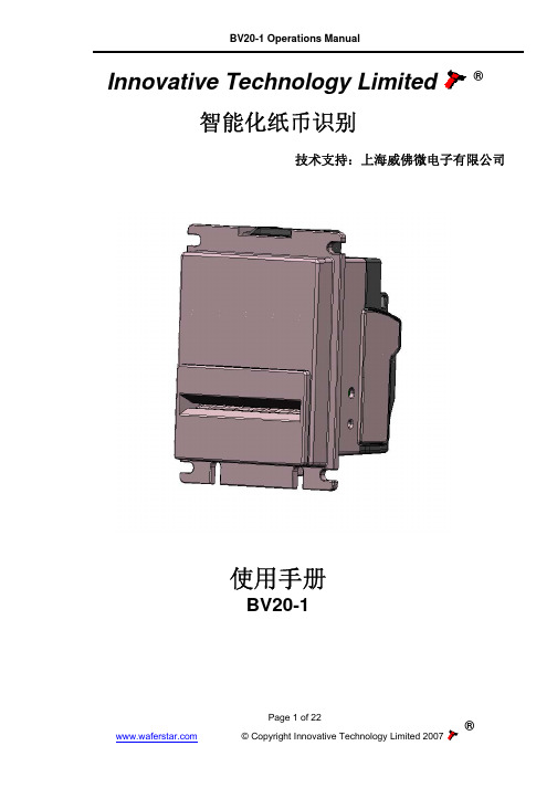
BV20-1 Operations Manual
Innovative Technology Limited ® 智能化纸币识别
技术支持:上海威佛微电子有限公司
Operations Manual
BV20-1
使用手册
BV20-1
Page 1 of 22
®
© Copyright Innovative Technology Limited 2007
电流,电压
供电电压 MDB IF5 供电电压 输入纹波电压 供电电流: 休眠电流 (低电压模式) 待机 工作 峰值
最小 +11V +18V
0
表格 Байду номын сангаас – 电源要求
最大 +15V +48V DC or 34V AC 0.25V @100 Hz
1.2mA 150mA 540mA 1700mA
接口电平 输入
带 2K2 上拉电阻的输出 最大下沉电流
低电平 0V To +0.5V
0.6V 50mA
表格 3 – 接口电平
高电平 +3.7 V +12V 主控板的上拉电平
Page 4 of 22
®
© Copyright Innovative Technology Limited 2007
BV20-1 使用手册
内容
1. 介绍.............................................................................................................................................. 3 2. 手册内容....................................................................................................................................... 3 3. 使用环境以及电源要求................................................................................................................. 4 4. 简要描述....................................................................................................................................... 5 5. 物理接口: 硬件 ............................................................................................................................. 6
5.1 接口所用管脚配置 .................................................................................................................... 6 5.2 设置按钮的功能 ........................................................................................................................ 8 5.2 表格 6 –设置按钮的功能........................................................................................................... 8
®
© Copyright Innovative Technology Limited 2007
3. 使用环境以及电源要求
BV20-1 使用手册
环境
最小
最大
温度 湿度
+3oC 5%
+50oC 95%
表格 1 – 环境要求
注意事项: • 如果输入电压低于 11 伏,BV20 将无法正常工作,拒收纸币。前面的面板指示灯将闪烁以指 示电源问题。 • 我们建议电源最大电流为 1.7A
BV20 程序设置模式 ..................................................................................................................... 8 BV20 配制卡程序设置模式........................................................................................................... 8 如何显示当前 BV20 的接口方式................................................................................................... 8 5.3 附加硬件功能............................................................................................................................ 8 6. 硬件接口协议: ............................................................................................................................ 10 6.1 并行输出:................................................................................................................................ 10 6.2 脉冲输出: ............................................................................................................................. 10 6.5 Smiley® 安全串口协议- SSP.................................................................................................. 10 6.6 MDB 协议 (MDB/ICP)............................................................................................................. 11 7. 如何使用BV20 配置卡................................................................................................................ 11 8. 机械安装..................................................................................................................................... 12 9. 日常维护..................................................................................................................................... 13 9.1 再校验。 ................................................................................................................................. 13 10. 支持工具..................................................................................................................................... 13 10.1 配置卡..................................................................................................................................... 13 10.2 ITL 纸币器管理软件 ................................................................................................................ 13 附件 B – 暂存功能 ......................................................................................................................... 13 附件 C – 接口工具 DA1 – DA2 ...................................................................................................... 14 附件 D – 配置卡 ............................................................................................................................. 16 附件 F – 低功耗模式 ...................................................................................................................... 22