2103.08石灰砂砾(石灰剂量5%),压实厚度每增减1cm
PKCS-#5:基于密码的密码系统说明书版本-2.0.B

组织:中国互动出版网(http://www。
china—pub。
com/)RFC文档中文翻译计划(http://www。
/compters/emook/aboute mook.htm)E—mail:ouyang@china-pub。
com译者:陶志荣(dick_hw jerrytaowx@)译文发布时间:2002—1—9版权:本中文翻译文档版权归中国互动出版网所有.可以用于非商业用途自由转载,但必须保留本文档的翻译及版权信息.Network Working GroupRequest for Comments:2898Category:InformationalB。
KaliskiRSA LaboratoriesSeptember 2000本备忘录的状态本文档为Internet社区提供信息. 它并未定义任何Internet标准.本备忘录的发布不受任何限制.版权声明Copyright (C) The Internet Society (2000). All Rights Reserved.摘要本备忘录代表源自RSA实验室的公钥密码系统标准(PKCS)系列的PKCS #5 v2.0的再版,变更控制仍保留在PKCS过程。
该文档的主体,除了安全性考虑一节,都是直接从那个规范中获得的.本文档提供基于口令的密码系统的实现建议,覆盖密钥导出函数,加密方案,消息鉴别方案,及与该技术等同的ASN.1语法。
建议的意图是供计算机和通信系统的一般程序使用,因此包括了相当数量的灵活性。
它们特别为敏感信息的保护设计,例如PKCS #8[25]中的私钥。
期望有基于这些规范的应用标准和实现轮廓可能包括附加的约束。
其它基于口令的密码技术,例如基于口令的密钥实体认证和密钥建立协议[4][5][26]不在本文档范围。
口令的选取原则也不在本文档范围。
1.介绍本文档为基于口令的密钥系统的实现提供建议,包括了下列的方面:•密钥导出函数•加密方案•消息鉴别方案•与该技术等同的ASN。
ADLRAN ATLAS 800PLUS 使用手册说明书
iv
Affidavit Requirements for Connection to Digital Services • An affidavit is required to be given to the telephone company whenever digital terminal equipment
901 Explorer Boulevard P.O. Box 140000
Huntsville, AL 35814-4000 (256) 963-8000
© 2000 ADTRAN, Inc. All Rights Reserved.
Prinns require that in this manual the following information be provided to the customer:
6. This unit contains no user-serviceable parts. 7. The following information may be required when applying to your local telephone company for
leased line facilities.
without encoded analog content and billing protection is used to transmit digital signals containing encoded analog content which are intended for eventual conversion into voiceband analog signals and transmitted on the network. • The affidavit shall affirm that either no encoded analog content or billing information is being transmitted or that the output of the device meets Part 68 encoded analog content or billing protection specifications. • End user/customer will be responsible for filing an affidavit with the local exchange carrier when connecting unprotected customer premise equipment (CPE) to 1.544 Mbps or subrate digital services. • Until such time as subrate digital terminal equipment is registered for voice applications, the affidavit requirement for subrate services is waived.
5g ssb hdl 代码

一、5G简介5G是第五代移动通信技术的简称,它将提供更快的数据传输速度和更可靠的连接,将极大地改变人们的生活和工作方式。
5G技术的发展促进了物联网、人工智能、智能制造等领域的快速发展,成为推动数字经济发展的关键技术之一。
二、SSB技术介绍SSB是5G中的一种重要技术,全称为Sync Signal Block,即同步信号块。
它是5G中的一种物理信道,用于进行小区搜索和同步。
SSB 的设计和部署对于5G网络的覆盖范围和性能有着重要的影响。
三、HDL代码的作用HDL代码是硬件描述语言(Hardware Description Language)的缩写,它是一种用于描述数字电路的语言,被广泛应用于数字电路的设计与验证。
在5G技术的研发中,HDL代码被用于设计5G基站与终端设备中的数字电路,如SSB信号的发射与接收模块。
四、5G与SSB技术的关系5G技术的发展离不开对SSB技术的不断优化和改进。
通过对SSB信号的频率、功率、波形等参数进行优化,可以提高5G网络的覆盖范围和信号质量,从而提升用户的网络体验。
五、HDL代码在SSB技术中的应用在5G基站的设计中,HDL代码被用于实现SSB信号的发射和接收模块。
通过HDL代码的编写,工程师可以实现对SSB信号的调制解调、功率控制、多天线技术等关键功能,从而确保5G网络的稳定性和性能。
六、HDL代码的优化为了提高5G网络的性能和效率,工程师们不断优化HDL代码,以适应不断变化的网络需求。
他们通过对HDL代码进行仿真、验证和调试,不断提升SSB技术在5G网络中的表现。
七、HDL代码的挑战与未来虽然HDL代码在5G网络中发挥着重要作用,但其面临着一些挑战,包括复杂的系统集成、功耗优化、多天线技术等。
未来,随着5G网络的不断普及和发展,HDL代码将会持续发挥着重要作用,并面临着更多的技术挑战。
八、总结5G与SSB技术的发展离不开HDL代码的支持与优化。
HDL代码在5G网络中扮演着重要的角色,通过对SSB信号等关键技术的优化和改进,将为用户提供更加稳定和快速的网络体验。
15中猜-广东-英语

!) & ' (
#) & ' (
*) & ' (
") & ' !"#$ % '! ! & " & (
"! (CD 7E9/(CD:;<=145 FGHI 4 5 1 J K L M < N O P > Q$@AB $"% &'( ! % )*+89567
&! ()*^_` ab)*^_`1:; +,-.$/01 & ' ( 2U7W678 XY7W >?)*^_`@AB $# &'( ! % )*+BCDEFGH67 *% (%T?)* c\% * $ * ! AUQ$ * $) /0 1 21 ; 5 2 0 5 2 L :8 5 1 J 5 ; 8> : 4 7 :3 :2 0 4 8L 5 5 J 5 7 3 E >2 &) V :2 :2 0 56 : A 4 5 8 ) ') V :2 :2 0 5? 5 1 I 0) V :@ : ;12 ; 4 () E) * !) /0 5 71 ; 5 2 0 5 : 4 7 :6 5 5 2 D> >2 &) & 2" * $E) 6) & 2% * $E) 6) & 2+ * $E) 6) ') () (%d?)* c\% * # * * AUQ$ * #) /0 1 2 4 8 2 0 5> 4 ; 9 8 @ 1 2 0 5 ;3 : 4 7 4 7N 7 9 1 7 37 : L > > &) K ; 1 A 5 9 9 4 7 ) > ') W 4 8 4 2 4 7 4 8 @ ; 4 5 7 3 8 ) >0 () M 1 A 4 7 5 5 2 4 7 ) >16 > () R 1 J 516 5 1 9 @ : ;0 4 6) * *) /0 1 2L 4 9 9 2 0 5> 4 ; 93 :@ : ;0 5 ; @ 1 2 0 5 ;: 7X 1 2 0 5 ; 8S 1 D &) ' B 4 61E ; 5 8 5 7 2 ) ') Y 4 7 4 6B D0 >0 E) (%2?)* c\% * "* + Q$ * ") M : L9 : 7 1 8 4 2 ; 1 4 7 5 3 4 72 0 5 4 ;0 : 6 5 2 : L 7 >0 &) X : ;1 ? : B 2 2 L :3 1 8 ) D ') X : ;1 ? : B 2 8 5 A 5 73 1 8 ) D () X : ;1 ? : B 2 2 5 73 1 8 ) D * %) /0 ; 58 : 6 5E 5 : 9 58 1 3 D1 E &) ' 5 I 1 B 8 5 2 0 5 : 7 20 1 A 51 7 9 1 I 5 8 2 : 9 4 A 5 4 7) D3 DE ') ' 5 I 1 B 8 5 2 0 5 A 5 9 : 8 2 2 0 5 4 ; ; 5 9 1 2 4 A 5 8 ) D () ' 5 I 1 B 8 5 2 0 5 ; 58 5 ; 4 : B 8 9 4 9 9 ) D1 D * +) /0 1 2L 4 9 9 2 0 5 : 7 1 2 5 @ : ; 2 0 5E 5 : 9 5 4 72 0 5 4 ;0 : 6 5 2 : L 7 D3 E &) ( 9 : 2 0 5 8 ) ') X : : 3 ) !"#$ % '! " & " & () R : 7 5 ) D
6633_6635最新错误代码_130121_V2

Err 2 说明复位方法1100 非正常 Unit ID 复位和重试1110 固件通讯状态异常 复位,重新确认 CAN 数据线,确认保险丝。
1111 固件通讯状态异常 1112 FDU 通讯状态异常1113 接受部(CAM) 非正常通讯状态 1114 验钞机(CBV) 非正常通讯状态 1115 废钞箱(RJB) 非正常通讯状态 1116 废钞通道(RJP) 非正常通讯状态 1117 钞箱1(CST1) 非正常通讯状态 1118 钞箱2(CST2) 非正常通讯状态 1119 钞箱3(CST3) 非正常通讯状态 111A 钞箱4(CST4) 非正常通讯状态 111B 固件非正常通讯状态 111C 固件非正常通讯状态 111D 固件非正常通讯状态 111E 固件非正常通讯状态111F 验钞机 SUB(CBV-SUB) 非正常通讯状态 1122 内部通讯错误- FDU 没有ACK 1123 内部通讯错误- CAM 没有ACK 1124 内部通讯错误- CBV 没有ACK 1125 内部通讯错误- RJB 没有ACK 1126 内部通讯错误- RJP 没有ACK 1127 内部通讯错误- 钞箱1 没有ACK 1128 内部通讯错误- 钞箱2 没有ACK 1129 内部通讯错误- 钞箱3 没有ACK 112A 内部通讯错误- 钞箱4 没有ACK 112F 内部通讯错误 CBV-SUB 没有 ACK 1132 内部通讯错误- No BUSY from FDU 1133 内部通讯错误- CAM 没有 BUSY 1134内部通讯错误- CBV 没有 BUSYSCRM 硬件错误代码由3个部分组成首先是保留一部分。
这2个字符可以被忽略。
第二部分是命令代码。
的代码固件命令,使用XFS 服务提供商计划。
最后一部分是错误代码。
可以分析这一领域的H/ W 错误状态。
H/ W 错误代码的详细信息,请看下页。
* Ref. 1: 循环模块硬件错误代码结构错误代码 (4)命令 (2)RESERVED (2)Err 说明复位方法1135 内部通讯错误- RJB 没有Busy 复位,重新确认 CAN 数据线,确认保险丝。
B4235物性表
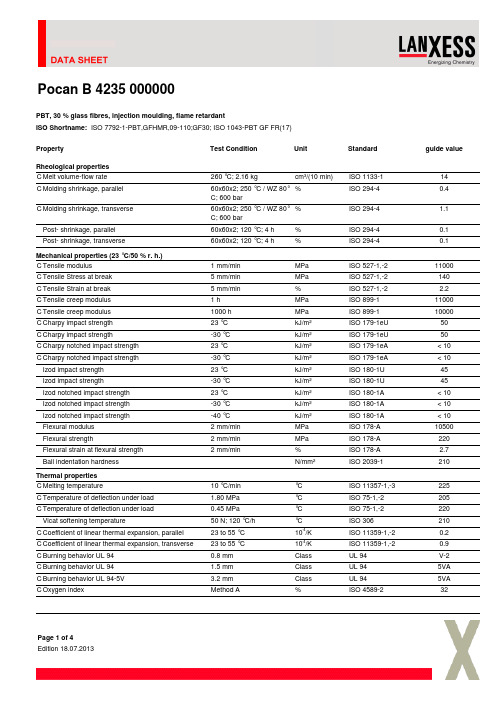
PBT,30%glass fibres,injection moulding,flame retardantISO Shortname:ISO 7792-1-PBT,GFHMR,09-110;GF30;ISO 1043-PBT GF FR(17)PropertyTest ConditionUnitStandardguide valueRheological properties C Melt volume-flow rate 260°C;2.16kgcm³/(10min)ISO 1133-114C Molding shrinkage,parallel 60x60x2;250°C /WZ 80°C;600bar%ISO 294-40.4C Molding shrinkage,transverse 60x60x2;250°C /WZ 80°C;600bar%ISO 294-4 1.1Post-shrinkage,parallel 60x60x2;120°C;4h %ISO 294-40.1Post-shrinkage,transverse60x60x2;120°C;4h%ISO 294-40.1Mechanical properties (23°C/50%r.h.)C Tensile modulus 1mm/min MPa ISO 527-1,-211000C Tensile Stress at break 5mm/min MPa ISO 527-1,-2140C Tensile Strain at break 5mm/min %ISO 527-1,-2 2.2C Tensile creep modulus 1h MPa ISO 899-111000C Tensile creep modulus 1000h MPa ISO 899-110000C Charpy impact strength 23°C kJ/m²ISO 179-1eU 50C Charpy impact strength -30°C kJ/m²ISO 179-1eU 50C Charpy notched impact strength 23°C kJ/m²ISO 179-1eA <10C Charpy notched impact strength -30°C kJ/m²ISO 179-1eA <10Izod impact strength 23°C kJ/m²ISO 180-1U 45Izod impact strength -30°C kJ/m²ISO 180-1U 45Izod notched impact strength 23°C kJ/m²ISO 180-1A <10Izod notched impact strength -30°C kJ/m²ISO 180-1A <10Izod notched impact strength -40°C kJ/m²ISO 180-1A <10Flexural modulus 2mm/min MPa ISO 178-A 10500Flexural strength2mm/min MPa ISO 178-A 220Flexural strain at flexural strength 2mm/min%ISO 178-A 2.7Ball indentation hardness N/mm²ISO 2039-1210Thermal properties C Melting temperature10°C/min °C ISO 11357-1,-3225C Temperature of deflection under load 1.80MPa °C ISO 75-1,-2205C Temperature of deflection under load 0.45MPa °C ISO 75-1,-2220Vicat softening temperature50N;120°C/h °C ISO 306210C Coefficient of linear thermal expansion,parallel 23to 55°C 10-4/K ISO 11359-1,-20.2C Coefficient of linear thermal expansion,transverse 23to 55°C 10-4/K ISO 11359-1,-20.9C Burning behavior UL 940.8mm Class UL 94V-2C Burning behavior UL 94 1.5mm Class UL 945VA C Burning behavior UL 94-5V 3.2mm Class UL 945VA C Oxygen indexMethod A%ISO 4589-232Pocan B 4235000000Page 1of 4PropertyTest Condition Unit Standard guide valueThermal conductivity23°C W/(m·K)ISO 83020.22Resistance to heat (ball pressure test)°C IEC 60695-10-2215Temperature index (Tensile strength)20000h°C IEC 60216-1140Halving interval (Tensile strength)°C IEC 60216-111.7Relative temperature index (Tensile strength)°CUL 746B 140Temperature index (Tensile impact strength)20000h °C IEC 60216-1135Halving interval (Tensile impact strength)°C IEC 60216-19.2Relative temperature index (Tensile impact strength)°CUL 746B 130Temperature index (Electric strength)20000h °C IEC 60216-1145Halving interval (Electric strength)°C IEC 60216-112.4Relative temperature index (Electric strength)°CUL 746B 130Glow wire test (GWFI)0.8mm °C IEC 60695-2-12960Glow wire test (GWFI) 1.6mm °C IEC 60695-2-12960Glow wire test (GWFI) 3.0mm °C IEC 60695-2-12960Glow wire test (GWIT)0.75mm °C IEC 60695-2-13725Glow wire test (GWIT) 1.6mm °C IEC 60695-2-13725Glow wire test (GWIT)3.0mm°CIEC 60695-2-13725Electrical properties (23°C/50%r.h.)C Relative permittivity 100Hz -IEC 60250 4.0C Relative permittivity 1MHz -IEC 60250 3.9C Dissipation factor 100Hz 10-4IEC 6025050C Dissipation factor 1MHz10-4IEC 60250160C Volume resistivity Ohm·m IEC 60093>1E13C Surface resistivity Ohm IEC 60093>1E15C Electric strength1mm kV/mm IEC 60243-129C Comparative tracking index CTI Solution A V IEC 60112175Electrolytic corrosion RatingIEC 60426A 1Other properties (23°C)C Water absorption (Saturation value)Water at 23°C %ISO 620.4C Water absorption (Equilibrium value)23°C;50%RH%ISO 620.1C Density kg/m³ISO 11831660Bulk densitykg/m³ISO 60800Material specific properties C Viscosity numbercm³/gISO 1628-593Processing conditions for test specimens C Injection molding-Melt temperature °C ISO 294250C Injection molding-Mold temperature °CISO 29480Processing recommendations Drying time circulating air dryer h -4-8Drying temperature circulating air dryer°C-120Pocan B 4235000000Page 2of 4PropertyTest ConditionUnit Standard guide value Residual moisture content %Acc.to Karl Fischer 0-0.02Melt temperature (Tmin -Tmax)°C -240-260Mold temperature°C-80-100C These property characteristics are taken from the CAMPUS plastics data bank and are based on the international catalogue of basic data for plastics according to ISO10350.Pocan B 4235000000Page 3of 4DisclaimerDisclaimer for sales productsThis information and our technical advice -whether verbal,in writing or by way of trials -are given in good faith but without warranty,and this also applies whereproprietary rights of third parties are involved.Our advice does not release you from the obligation to verify the information currently provided -especially that contained in our safety data and technical information sheets -and to test our products as to their suitability for the intended processes and uses.The application,use and processing of our products and the products manufactured by you on the basis of our technical advice are beyond our control and,therefore,entirely your own responsibility.Our products are sold in accordance with the current version of our General Conditions of Sale and Delivery.Test valuesUnless specified to the contrary,the values given have been established on standardized test specimens at room temperature.The figures should be regarded as guide values only and not as binding minimum values.Kindly note that,under certain conditions,the properties can be affected to a considerable extent by the design of the mould/die,the processing conditions and the coloring.Processing noteUnder the recommended processing conditions small quantities of decomposition product may be given off during processing.To preclude any risk to the health and well-being of the machine operatives,tolerance limits for the work environment must be ensured by the provision of efficient exhaust ventilation and fresh air at theworkplace in accordance with the Safety Data Sheet.In order to prevent the partial decomposition of the polymer and the generation of volatile decomposition products,the prescribed processing temperatures should not be substantially exceeded.Since excessively high temperatures are generally the result of operator error or defects in the heating system,special care and controls are essential in these areas.LANXESS DEUTSCHLAND GMBH |D -51369LEVERKUSEN ©LANXESS DeutschlandGmbHPocan B 4235000000Page 4of 4。
血管紧张素Ⅱ通过抑制人心房成纤维细胞BKCa通道诱导心房纤维化

基金项目:泸州市人民政府西南医科大学科技战略合作项目(2021LZXNYD Z07,2021LZXNYD J26)通信作者:于风旭,E mail:yuluchuan@163.com·论著·血管紧张素Ⅱ通过抑制人心房成纤维细胞BKCa通道诱导心房纤维化贾春森 李磊 李劲平 谭宏伟 周伟 聂永梅 于风旭(西南医科大学附属医院心脏大血管外科,四川泸州646000)【摘要】目的 探讨在血管紧张素Ⅱ(AngⅡ)诱导心房纤维化的过程中,大电导钙激活钾通道(BKCa通道)的作用机制。
方法 通过组织块贴壁法获取原代人心房成纤维细胞,使用免疫荧光染色进行鉴定。
用浓度为500nmol/L的AngⅡ处理人心房成纤维细胞24h,实时荧光定量PCR与蛋白质印迹法用于检测处理前后纤维化标志基因α 平滑肌肌动蛋白(α SMA)、胶原蛋白Ⅰ(collagenⅠ)和胶原蛋白Ⅲ(collagenⅢ),以及BKCa通道的α与β亚基的mRNA和蛋白表达水平,全细胞膜片钳技术检测AngⅡ处理前后的BKCa通道的电流变化。
结果 (1)人心房成纤维细胞经AngⅡ处理后,α SMA、collagenⅠ和collagenⅢ的mRNA和蛋白表达水平升高;(2)经过AngⅡ处理后,BKCa通道α及β亚基mRNA和蛋白表达水平降低;(3)人心房成纤维细胞存在功能正常的BKCa通道,具有电压依赖性;(4)人心房成纤维细胞BKCa通道的宏观电流幅度在经AngⅡ处理后降低;(5)在人心房成纤维细胞上过表达BKCa通道α亚基后,纤维化标志物α SMA、collagenⅠ和collagenⅢ的表达受到了明显抑制。
结论 AngⅡ可能通过抑制人成纤维细胞BKCa通道的表达和功能来诱导人心房成纤维细胞的纤维化,并最终导致心房纤维化。
【关键词】心房纤维化;血管紧张素Ⅱ;人心房成纤维细胞;大电导钙激活钾通道【DOI】10 16806/j.cnki.issn.1004 3934 2023 11 020AngiotensinⅡInducesAtrialFibrosisbyInhibitingBKCaChannelinHumanAtrialFibroblastJIAChunsen,LILei,LIJinping,TANHongwei,ZHOUWei,NIEYongmei,YUFengxu(DepartmentofCardiovascularSurgery,TheAffiliatedHospitalofSouthwestMedicalUniversity,Luzhou646000,Sichuan,China)【Abstract】Objective Toinvestigatethemechanismoflargeconductancecalcium activatedpotassiumchannel(BKCa)inangiotensinⅡ(AngⅡ) inducedatrialfibrosis.Methods Primaryhumanatrialfibroblastswereobtainedbytissueblockattachmentmethodandidentifiedbyimmunofluorescencestaining.HumanatrialfibroblastsweretreatedwithAngⅡ(500nmol/L)for24h.Real timefluorescentquantitativePCRandWesternblotwereusedtodetectthemRNAandproteinexpressionlevelsoffibrosismarkergenesα SMA,collagenⅠandcollagenⅢ,aswellasαandβsubunitsofBKCachannelsbeforeandaftertreatment.AndwholecellpatchclamptechniquewasusedtodetectthecurrentchangesofBKCachannelsbeforeandafterAngⅡtreatment.Results (1)AfterAngⅡtreatmentofhumanatrialfibroblasts,themRNAandproteinexpressionlevelsofα SMA,collagenⅠandcollagenⅢincreased;(2)AfterAngⅡtreatment,themRNAandproteinexpressionofBKCachannelαandβsubunitsdecreased;(3)HumanatrialfibroblastsexistnormalBKCachannel,whicharevoltagedependent;(4)MacrocurrentamplitudeofBKCachannelinhumanatrialfibroblastsdecreasedafterAngⅡtreatment;(5)AfteroverexpressionofBKCachannelαsubunitonhumanatrialfibroblasts,themRNAandproteinexpressionlevelsoffibrosismarkerα SMA,collagenⅠandcollagenⅢdecreasedsignificantly.Conclusion AngⅡmayinducefibrosisinhumanatrialfibroblastsbyinhibitingtheexpressionandfunctionofBKCachannel,andfinallyinduceatrialfibrosis.【Keywords】Atrialfibrosis;AngiotensinⅡ;Humanatrialfibroblast;Largeconductancecalcium activatedpotassiumchannel 心房颤动(房颤)是临床上最为常见的心律失常,有较高的发病率与死亡率,其发病机制复杂,其中以心房纤维化为代表的结构重构是重要始动因素[1]。
matlab中crtbp函数的用法
matlab中crtbp函数的用法全文共四篇示例,供读者参考第一篇示例:Matlab中的crtbp函数是一个非常常用的函数,用来模拟三体问题中的地月问题。
在地月问题中,太阳是一个质点,地球和月球则分别是两个质点,它们之间通过引力相互作用。
这种模拟可以帮助我们更好地理解三体问题的复杂性,研究宇宙中各种天体之间的运动规律。
在使用crtbp函数之前,我们首先需要了解它的基本用法和参数。
crtbp函数的格式为:\[crtbp(mu0, mu1, mu2)\],其中mu0代表地球-月球系统的质量参数,mu1和mu2则分别表示地球和月球与太阳系统的质量参数。
在地月问题中,mu0通常取值为0.0123,mu1为0.81,mu2为0.0123,这是一个标准的设定。
crtbp函数的返回值是一个6维向量\[y(1), y(2), y(3), y(4), y(5),y(6)\],其中y(1)和y(2)表示小行星的x和y坐标,y(3)和y(4)表示小行星的x和y方向的速度,y(5)和y(6)则表示小行星相对于质心的z坐标和速度。
crtbp函数的用法非常简单,只需要输入地球-月球系统和地球-月球-太阳系统的质量参数,就可以得到小行星在这个系统中的运动轨迹。
我们可以利用这个函数来研究小行星在地月系统中的运动规律,以及判断可能的稳定轨道和不稳定轨道。
除了直接调用crtbp函数进行数值模拟外,我们还可以结合其他函数和工具箱,进一步分析三体问题的性质和演化过程。
在Matlab中,有许多内置函数和工具箱可以用来处理复杂的动力学系统,例如ode45函数用于求解常微分方程组,对动力学系统的演化进行模拟。
通过在Matlab中使用crtbp函数和其他相关工具,我们可以更好地了解三体问题的行为,预测小行星在地月系统中的轨道变化,甚至研究可能的碰撞事件和轨道交叉。
这对于理解宇宙中各种天体之间的相互作用,以及预测一些潜在的天体运动的影响具有重要的意义。
囊胚培养液中游离DNA的重要染色体整倍性研究
·长篇论著·囊胚培养液中游离DNA的重要染色体整倍性研究黄锦 加加林 姚雅馨 陆思嘉 党玉姣 乔杰 刘平基金项目:国家重点研发计划(2018YFC1003104);国家自然科学基金(82071721);北京大学第三医院院临床重点项目(BYSY2018015)作者单位:100191,北京大学第三医院妇产科(黄锦,加加林,党玉姣,乔杰,刘平);国家妇产疾病临床医学研究中心(北京大学第三医院)(黄锦,加加林,党玉姣,乔杰,刘平);亿康基因科技有限公司(姚雅馨,陆思嘉)通信作者:刘平(pingliu7703@sina.com)【摘要】 目的 探讨利用培养液中游离DNA检测对应囊胚的13、15、16、18、21、22号染色体整倍性的效率。
方法本研究共纳入239枚囊胚,所有的胚胎均来源于PGT A周期。
囊胚活检的滋养层细胞采用SNP芯片检测胚胎的整倍性;培养液游离DNA采用无创胚胎染色体筛查(NICS)方法检测整倍性;采用盲法比较两者的结果。
计算NICS在检测13、15、16、18、21、22号染色体整倍性的敏感性、特异性、诊断效率、阳性预测值和阴性预测值。
结果239枚囊胚中的209枚有NICS结果,NICS检出率为87 5%(209/239)。
NICS方法在检测13、15、16、18、21、22号染色体的特异性、效率比较高,均>90%,NICS结果的阴性预测值超过97%;但是敏感性波动较大(33%~100%),阳性预测值较低(<50%)。
结论NICS方法可以检测囊胚整倍性。
当NICS结果显示这些重要染色体(13、15、16、18、21、22号染色体)为整倍体时,对应囊胚该条染色体整倍性几率高;但是当NICS结果显示这些重要染色体为非整倍体时,对应胚胎并不一定为非整倍体。
【关键词】 游离DNA; 非整倍体; 囊胚; 胚胎无创染色体筛查技术; 胚胎植入前遗传学检测【中图分类号】 R71StudyontheimportantchromosomeeuploidyofcellfreeDNAinblastocystculturemediumHUANGJin,JIAJialin,YAOYaxin,LUSijia,DANGYujiao,QIAOJie,LIUPing.DepartmentofObstetricsandGynecology,PekingUniversityThirdHospital,Beijing100191,China[Abstract] Objective ToexploretheefficiencyofcellfreeDNAinculturemediatodetectchromosome13,15,16,18,21and22aneuploidyoftheblastocysts.MethodsAtotalof239blastocystswereincludedinthisstudy,andallwerederivedfromPGT Acycles.SNParraywasusedtodetecttheaneuploidyoftrophoblastcellsofblastocystbiopsy.NICSwasusedtodetecttheaneuploidyofcellfreeDNAinculturemedia.Wecomparedtheresultsofthetwomethodsusingblind.Wealsocalculatedthesensitivity,specificity,diagnosticefficiency,positivepredictivevalueandnegativepredictivevalueofNICSinthedetectionofchromosomes13,15,16,18,21and22aneuploidy.ResultsAmong239blastocystsincludedinthisstudy,209blastocystshadNICSresults,andthedetectionrateofNICSwas87 5%(209/239).ThespecificityandefficiencyofNICSinthedetectionofchromosomes13,15,16,18,21and22werehigherthan90%,andthenegativepredictivevalueofNICSwasover97%.However,thesensitivityfluctuatedgreatly(33%~100%),andthepositivepredictivevaluewaslowerthan50%.ConclusionNICScandetectblastocystaneuploidy.Whenthechromosomes13,15,16,18,21,22areeuploid,theprobabilityishigh.Theembryoisnotnecessarilyaneuploidwhenthechromosomesareaneuploid.[Keywords] cellfreeDNA; aneuploidy; blastocyst; noninvasivechromosomescreening(NICS); preimplantationgenetictesting 近年来胚胎培养液中存在游离DNA(cellfreeDNA,cfDNA)已经在生殖领域引起了越来越多的关注[1]。
浙江省G5联盟2024年高二4月期中物理试题含答案

绝密★考试结束前2023学年第二学期浙江G5联盟期中联考高二年级物理学科试题考生须知:1.本卷共8页满分100分,考试时间90分钟。
2.答题前,在答题卷指定区域填写班级、姓名、考场号、座位号及准考证号并填涂相应数字。
3.所有答案必须写在答题纸上,写在试卷上无效。
4.考试结束后,只需上交答题纸。
选择题部分一、选择题Ⅰ(本题共13小题,每小题3分,共39分。
每小题列出的四个备选项中只有一个是符合题目要求的,不选、多选、错选均不得分)1.下列物理量中为矢量且单位符号正确的是()A.电流(A)B.电场强度(C)C.磁通量(wb)D.磁感应强度(T)2.2024年2月27日,某电动垂直起降航空器完全模拟一家人从深圳蛇口邮轮母港飞至珠海九洲港码头,将单程2.5到3小时的地面车程缩短至20分钟。
该航空器最大航程250公里,最大巡航速度200公里/小时,最多可搭载5人,则下列说法中正确的是()A.航程250公里代表位移B.最大巡航速度200公里/小时指的是瞬时速度C.计算航空器在两地飞行时间时不能视作质点D.航空器升空过程中,以某一乘客为参考系,其他乘客都向上运动3.下列说法符合物理学史的是()A.奥斯特发现了电磁感应现象B.赫兹预言了电磁波的存在C.法拉第最先提出了微观领域的能量量子化概念D.英国物理学家卡文迪许测量出了引力常量G的数值4.质量为m的链球在抛出前的运动情景如图所示,假设在运动员的作用下,链球与水平面成一定夹角的斜面上从1位置匀速转动到最高点2位置,则链球从1位置到2位置的过程中下列说法正确的是()A .链球需要的向心力保持不变B .链球在转动过程中机械能守恒C .运动员的手转动的角速度等于链球的角速度D .运动员的手转动的线速度大于链球的线速度5.如图所示,质量为m 的磁铁贴吸于固定的竖直金属板上,初始时作用于磁铁的推力F 既平行于水平面也平行于金属板,此时金属板对磁铁的作用力为1F 。
现保持推力F 的大小不变,将作用于磁铁的推力F 方向改为垂直金属板,此时金属板对磁铁作用力为2F 。
富士电机 PXH数字显示式调节器 说明书

-4-
1.2 设置及配线
· 本调节器适合于在下述的条件下设置。
环境温度 环境湿度 设置种类 污染度
-10~50°C
90%RH以下(应不结露)
Ⅱ
根据IEC 1010-1
2
· 请确保温度传感器与达到或产生下表所示电压值的场所之间,保持下表所示的爬电距离和空间距离。 无法满足上述要求时,EN61010的安全承诺可能无效。
·CD-ROM ..................................................... 1张
使用说明书
用户手册
通信功能使用说明书(Modbus) 通信示范程序
CD内容
参数装载器使用说明书
参数装载软件
·安装配件...................................................... 2个
Ch2
(控制参数).....................................39
Ch4
(控制参数组态) .............................40
Ch7
(监视器) ........................................42
Ch8
(输入输出定义) .............................42
-3-
使用前须知 安全注意事项
使用前请认真阅读该“安全注意事项”,正确使用本产品。 这里列出的注意事项记载着与安全有关的重要内容,请务必遵守。安全注意事项的等级分为“警告”和 “注意”。
警 告 如使用不当,可能导致死亡或者重伤。
注意
如使用不当,可能导致使用人员受伤及 发生物质损失。
COMTECH570L设备使用说明
CDM-570L卫星调制解调器设备使用说明注意:所有参数设置,请在中心站管理人员指导下进行!!!一、卫星调制解调器设备介绍本系统卫星调制解调器选用美国ComtechEFData公司生产的CDM-570L。
CDM-570L是一台L波段中频的调制解调器,支持连接LNB和BUC射频设备。
支持快捕解调,可通过升级支持Turbo Product Codec编码,也可升级到支持8PSK 和16-QAM调制。
卫星调制解调器CDM-570LCDM-570L的设计是以固件( firmware)和可编程门阵列(FPGA)为基础, 通过串口可容易地对内部闪存(Flash)进行升级。
在1U的设备封装里提供了高灵活性和出色的性能。
主要性能●950-1950 MHz L波段中频●数据速率从2.4 kbps到5 Mbps●快速捕获解调(±32 kHz捕获范围,64 kbps,1/2 QPSK:平均150毫秒)●最高可支持BPSK,QPSK,OQPSK,8-PSK,16-QAM多种调制方式●前向纠错可支持Turbo Product Codec,维特比,Reed-Solomon和TCM●自动上行功率控制(AUPC)及EDMAC功能●支持非平衡环路时钟●内置1:1备份控制器(Y-电缆用于数据,简单和并非昂贵的外部切换模块用于IF切换)●可支持和连接LNB、BUC●可提供BUC 10MHz参考信号和建立FSK通信,BUC供电电源可选●LNB供电和外10MHz参考●后向兼容CDM-500/CDM-550,CDM-550T和CDM-600、CDM-600L●支持以太监控接口●可选IP数据接口模块●可配外置1:1和1:10冗余切换开关Turbo Product Codec●CDM-570L提供传统的前项纠错(FEC)方式外,还可升级支持TurboProduct Codec (TPC)编码作为选项。
TPC技术提高了编码增益,降低了编码延时,并提供可观的带宽节省。
QB 1.5使用手册

使用手册目录1QBR主功能 (3)1.1实时行情 (3)1.1.1最优报价 (3)1.1.2我的关注 (9)1.1.3报价变动与实时成交 (13)1.1.4国债期货 (16)1.2基础数据 (20)1.2.1经纪商日评 (20)1.2.2债券日历 (20)1.3债券设置 (22)1.3.1筛选管理 (22)1.3.2提醒管理 (24)2QBA主功能 (27)2.1债券计算器 (27)2.2持有期计算器 (30)2.3综合分析 (37)2.4集成定价 (40)2.5曲线分析 (47)2.6融资杠杆 (48)2.7成交分析 (53)3辅助功能 (59)3.1窗口置顶、最大化及弹出 (59)3.2ESC窗口快捷关闭 (59)3.3用户反馈 (59)3.4在线客服 (59)3.5QB设置 (59)4网络设置 (60)1QBR主功能1.1实时行情1.1.1最优报价a)查看最优报价实时更新的最优报价情况可以在<最优报价>窗口中查看。
其中,“全部”标签页显示本账户下所有有权限的经纪公司的实时报价,其他标签页显示不同货币经纪公司的实时报价。
经纪商标签页可以拖动,拖动同时“我的关注”和“个券详情”中的经纪商位置联动,该排序排序保存在服务器。
选中相应标签页,如下图所示,即可以查看该部分实时报价。
●Bid:买盘价●Ofr:卖盘价●Vol.Bid:买盘量●Vol.Ofr:卖盘量b)筛选功能可根据各种条件对债券进行筛选。
需要对所有筛选条件进行多选时,按住ctrl点击相关条件即可。
●产品类型:筛选条件分为地方债、国债、央票、金融债、地方债、短融、中票、企业债和其他(包括COB、CBB、NCB、CSB、CBS、MBS、LBS等)。
●剩余期限:可依据固定的剩余期间进行筛选。
当固定条件无法满足时,可依据需求自定义期限:在中可输入剩余期限。
点击可以切换筛选条件,中选择到期日的区间范围。
●双边:可筛选到双边报价的债券报价。
UM805 811 812 4引脚μP电压监控器带手动复位输入说明书
4-Pin μP Voltage Monitors with Manual Reset InputUM805/811/812 SOT143General DescriptionThe UM805/811/812 are low-power microprocessor (μP) supervisory circuits used to monitor power supplies in μP and digital systems. They provide excellent circuit reliability and low cost by eliminating external components and adjustments when used with 5V-powered or 3V-powered circuits. The UM805/811/812 also provide a debounced manual reset input.These devices perform a single function: They assert a reset signal whenever the V CC supply voltage falls below a preset threshold, keeping it asserted for at least 140ms after V CC has risen above the reset threshold. Reset thresholds are available for operation with a variety of supply voltages.The UM805 has an open-drain output stage, while the UM811/812 have push-pull outputs. The UM805’s open-drain RESET _____________output requires a pull-up resistor that can be connected to a voltage higher than V CC . The UM805/811 have an active-low RESET _____________output, while the UM812 has an active-high RESET output. The reset comparator is designed to ignore fast transients on V CC , and the outputs are guaranteed to be in the correct logic state for V CC down to 1V .Low supply current makes the UM805/811/812 ideal for use in portable equipments. The devices come in a 4-pin SOT143 package.ApplicationsFeaturesz Computers z Controllersz Portable/Battery-Powered Equipments z Intelligent Instrumentsz Critical μP and μC Power Monitoringz No External Components z V CC Transient Immunityz Correct Logic Output Guaranteed to V CC =1.0V z Precision V CC Monitoring of 3.0V, 3.3V and 5.0V Suppliesz 2μA Supply Currentz 140ms Minimum Power-On Reset Pulse Width z Guaranteed Over TemperaturezAvailable in 3 Output Configurations: Open-Drain Active-Low RESET __________Output (UM805)Push-Pull Active-Low RESET __________Output(UM811) Push-Pull Active-High RESET Output (UM812) z 4-Pin SOT143 PackagezWide Operation Temperature: -40°C to +85°CPin Configurations Top ViewOrdering InformationUM8 XX Z P XX: Output Type =05 Open-Drain Active Low =11 Push-Pull Active Low =12 Push-Pull Active High Z: Reset Threshold (V) =L 4.63 =M4.38 =J 4.00 =T 3.08 =S 2.93 =R 2.63 =Z 2.32P: Package Type =E SOT143Typical Operating CircuitM: Month Code UM805/811/812SOT143Pin DescriptionPinNumberPin Name Function1 GND Ground 2RESET ______________ (UM805/811) Active-Low Reset Output. RESET _____________remains low while V CC is below the reset threshold or while MR _______is held low. It remains low for the Reset Active Timeout Period (t RP ) after the reset conditions areterminated. See Figure 1. UM811:CMOS push-pull output (sources and sinks current).UM805: Open-drain, active low, NMOS output (sinks current only). Connect a pull-up resistor from RESET ______________to any supply voltage up to 6V. RESET (UM812)Active-High Reset Output. RESET remains high while V CC is below the reset threshold or while MR _______is held low. RESET remains high forReset Active Timeout Period (t RP ) after the reset conditions are terminated.3MR _______Manual Reset Input. A logic low on MR _______asserts reset. Reset remains asserted as long as MR _______ is low and for 240ms after MR _______returnshigh. This active-low input has an internal 20k Ω pull-up resistor. It can be driven from a TTL or CMOS-logic line, or shorted to ground with a switch. Leave open if unused. See Figure 2. 4 V CC+5V, +3.3V or +3V Supply VoltageAbsolute Maximum Ratings (Note 1)Symbol Parameter Value Unit V CC Supply Voltage-0.3 to +6.0 VRESET, RESET _____________(Push-Pull) -0.3 to (V CC +0.3) RESET _____________(Open-Drain) -0.3 to +6.0I CC Input Current, V CC , MR _______20 mA I O Output Current, RESET, RESET _____________20 mA P D Continuous Power Dissipation (Derate 4mW/°C above 70°C) 320 mW T A Operating Temperature Range -40 to +105 °C T STGStorage Temperature Range-65 to +160°C Lead Temperature (Soldering, 10s) +300 °CNote 1: Stresses beyond those listed under “Absolute maximum Ratings” may cause permanent damage to the device. These are stress ratings only and functional operation of the device at these or any other conditions beyond those indicated in the operational sections of the specifications are not implied. Exposure to absolute maximum rating conditions for extended periods may affect device reliability.Electrical Characteristics(V CC =5V for L/M/J versions, V CC =3.3V for T/S versions, V CC =3V for R version, and V CC =2.5V for Z version, T A =-40°C to +85°C, unless otherwise noted. Typical values are at T A =+25°C.) (Note 2)SymbolParameterConditionsMinTypMaxUnitV CC Supply VoltageRange T A =0°C to +70°C1.05.5VI CCSupply Current2.0 5.0μA V TH+Reset ThresholdL VersionT A =+25°C 4.56 4.63 4.70VT A =-40°C to +85°C4.504.75M VersionT A =+25°C 4.31 4.38 4.45T A =-40°C to +85°C4.254.50J VersionT A =+25°C 3.93 4.00 4.06T A =-40°C to +85°C3.894.10T VersionT A =+25°C 3.04 3.08 3.11 T A =-40°C to +85°C 3.00 3.15 S VersionT A =+25°C 2.89 2.93 2.96T A =-40°C to +85°C2.853.00R VersionT A =+25°C 2.59 2.63 2.66T A =-40°C to +85°C2.552.70Z VersionT A =+25°C 2.28 2.32 2.35T A =-40°C to +85°C 2.25 2.38 Reset ThresholdTempco150ppm/°CV CC to Reset Delay(Note 3) 10 μs t RP Reset Active Timeout Period140 240 560 mst MR MR ______Minimum Pulse Width 10 μs MR ______Glitch Immunity (Note 4) 100 ns t MD MR ______ to Reset Propagation Delay0.5μsV IH MR ______Input ThresholdV CC >V TH(MAX)UM805/811/812LE/ME/JE 2.3 VV IL 0.8 V IH V CC >V TH(MAX)UM805/811/812TE/SE/RE/ZE0.7×V CCV IL0.25×V CCMR ______Pull-Up Resistance10 20 30k ΩElectrical Characteristics (Continued)(V CC =5V for L/M/J versions, V CC =3.3V for T/S versions, V CC =3V for R version, and V CC =2.5V for Z version, T A =-40°C to +85°C, unless otherwise noted. Typical values are at T A =+25°C.) (Note 2)SymbolParameter ConditionsMinTypMaxUnitV OHRESET Output VoltageI SOURCE =150μA, 1.8V<V CC <V TH(MIN) UM812LE/ME/JE/TE/SE/RE/ZE0.8×V CCV V OLI SINK =1.2mA UM812TE/SE/RE/ZE0.3 I SINK =3.2mA UM812LE/ME/JE0.4 V OHRESET ____________OutputVoltageI SOURCE =500μA, V CC >V TH(MAX)UM811TE/SE/RE/ZE0.8×V CCVI SOURCE =800μA, V CC >V TH(MAX)UM811LE/ME/JEV CC -1.5V OLI SINK =1.2mA, V CC =V TH(MIN) UM805/811TE/SE/RE/ZE 0.3 I SINK =3.2mA, V CC =V TH(MIN) UM805/811LE/ME/JE0.4I SINK =50μA, V CC >1.0V 0.3Note 2: Production testing done at T A =+25°C; limits over temperature guaranteed by design only. Note 3: RESET _____________output for UM805/811; RESET output for UM812.Note 4: “Glitches” of 100ns or less typically will not generate a reset pulse.Typical Operating Characteristics(T A =+25°C, unless otherwise noted.)V CC =3.3VSupply Current vs. Temperature(UM811RE) Power-down RESET Delay vs. Temperature(UM811RE)Power-up RESET Timeout vs. TemperatureDetailed DescriptionRESET TimingThe reset signal is asserted LOW for the UM811 and HIGH for the UM812 when the power supply voltage falls below the threshold trip voltage and remains asserted for at least 140ms after the power supply voltage has risen above the threshold.Figure 1. RESET vs. V CC Timing DiagramThe reset signal is asserted LOW for the UM811 and HIGH for the UM812 when MR _______is low and remains asserted for at least 140ms after MR _______ishigh.MRRESETRESETV CC0V V CC0VFigure 2. RESET vs. MR _______Timing DiagramReset OutputA microprocessor’s (µP’s) reset input starts the µP in a known state. These μP supervisory circuits assert reset to prevent code execution errors during power-up, power-down, or brownout conditions. RESET _____________is guaranteed to be a logic low for V CC >1V . Once V CC exceeds the reset threshold, an internal timer keeps RESET _____________ low for the reset timeout period; after this interval, RESET _____________goes high. If a brownout condition occurs (V CC dips below the reset threshold), RESET _____________goes low. Any timeV CC goes below the reset threshold, the internal timer resets to zero, and RESET _____________goes low. The internal timer starts after V CC returns above the reset threshold, and RESET _____________remains low for the reset timeout period. The manual reset input (MR _______) can also initiate a reset. See the Manual Reset Input section. The UM812 has an active-high RESET output that is the inverse of the UM805/811’s RESET _____________ output. The UM805 uses an open-drain output, and the UM811/812 have a push-pull output stage. Connect a pull-up resistor on the UM805’s RESET _____________output to any supply between 0 and 6V .Manual Reset InputMany μP-based products require manual reset capability, allowing the operator, a test technician, or external logic circuitry to initiate a reset. A logic low on MR _______ asserts reset. Reset remains asserted while MR _______ is low, and for the Reset Active Timeout Period (t RP ) after MR _______returns high. This input has an internal 20k Ω pull-up resistor, so it can be left open if it is not used. MR _______can be driven with TTL or CMOS-logic levels, or with open-drain/collector outputs. Connect a normally open momentary switch from MR _______to GND to create a manual-reset function; external debounce circuitry is not required. If MR _______is driven from long cables or if the device is used in a noisy environment, connecting a 0.1μF capacitor from MR _______to ground provides additional noise immunity.Reset Threshold AccuracyThe UM805/811/812 are ideal for systems using a 5V±5% or 3V±5% power supply with ICs specified for 5V±10% or 3V±10%, respectively. They are designed to meet worst-case specifications over temperature. The reset is guaranteed to assert after the power supply falls out of regulation, but before power drops below the minimum specified operating voltage range for the system ICs. The thresholds are pre-trimmed and exhibit tight distribution, reducing the range over which an undesirable reset may occur.Applications InformationNegative-Going V CC TransientsIn addition to issuing a reset to the µP during power-up, power-down, and brownout conditions, the UM805/811/812 are relatively immune to short-duration negative-going V CC transients (glitches). Figure 3 shows typical transient duration vs. reset comparator overdrive, for which the UM805/811/812 do not generate a reset pulse. The graph was generated using a negative-going pulse applied to V CC , starting above the actual reset threshold and ending below it by the magnitude indicated (reset comparator overdrive). The graph indicates the typical maximum pulse width a negative-going V CC transient may have without causing a reset pulse to be issued. As the magnitude of the transient increases (goes farther below the reset threshold), the maximum allowable pulse width decreases. Typically, for the UM8_ _LE/ME/JE, a V CC transient that goes 125mV below the reset threshold and lasts 40µs or less will not cause a reset pulse to be issued. A 0.1µF capacitor mounted as close as possible to the V CC provides additional transient immunity.Figure 3. Maximum Transient Duration without Causing a Reset Pulsevs. Reset Comparator OverdriveEnsuring a Valid RESET ______________Output Down to V CC =0V When V CC falls below 1V , the UM811 RESET _____________output no longer sinks current—it becomes an open circuit. Therefore, high-impedance CMOS-logic inputs connected to RESET _____________can drift to undetermined voltages. This presents no problem in most applications since most µP and other circuitry is inoperative with V CC below 1V . However, in applications where RESET _____________must be valid down to 0V , adding a pull-down resistor to RESET _____________pin will causes any stray leakage currents to flow to ground, holding RESET _____________low (Figure 4). R1’s value is not critical; 100k Ω is large enough not to load RESET _____________ and small enough to pull RESET _____________toground. A 100k Ω pull-up resistor to V CC is also recommended for the UM812 if RESET is required to remain valid for V CC <1V .UM8__LE/ME/JEUM8TE/SE/RE/ZEFigure 4. RESET ____________Valid to V CC =Ground CircuitInterfacing to μPs with Bidirectional Reset PinsμPs with bidirectional reset pins (such as the Motorola68HC11 series) can contend with the UM811/812 reset outputs. If, for example, the UM811 RESET ______________output is asserted high and the μP wants to pull it low, indeterminate logic levels may result. To correct such cases, connect a 4.7k Ω resistor between the UM811 RESET ______________(or UM812 RESET) output and the μP reset I/O (Figure 5). Buffer the reset output to other system components.Figure 5. Interfacing to μPs with Bidirectional Reset I/OUM805 Open-Drain RESET ______________Output Allows Use with Multiple SuppliesGenerally, the pull-up connected to the UM805 will connect to the supply voltage that is being monitored at the IC’s V CC pin. However, some systems may use the open-drain output to level-shift from the monitored supply to reset circuitry powered by some other supply (Figure 6). Note that as the UM805’s V CC decreases below 1V, so does the IC’s ability to sink current at RESET _____________. Also, with any pull-up, RESET _____________will be pulled high as V CC decays toward 0. The voltage where this occurs depends on the pull-up resistor value and the voltage to which it is connected.Figure 6. UM805 Open-Drain RESET _____________Output Allows Use with Multiple SuppliesPackage InformationUM805/811/812 SOT1430.25End ViewSelection TablePart NumberRESETThreshold(V)TimeoutPeriod(ms)Output TypeMarkingCodePackageTypeShipping QtyUM805LE 4.63 240 Open-Drain,Active Low05LSOT1433000pcs/7InchTape & ReelUM805ME 4.38 240 Open-Drain,Active Low05MUM805JE 4.00 240 Open-Drain,Active Low05JUM805TE 3.08 240 Open-Drain,Active Low05TUM805SE 2.93 240 Open-Drain,Active Low05SUM805RE 2.63 240 Open-Drain,Active Low05RUM805ZE 2.32 240 Open-Drain,Active Low05ZUM811LE 4.63 240Push-Pull,Active Low11LUM811ME 4.38 240Push-Pull,Active Low11MUM811JE 4.00 240Push-Pull,Active Low11JUM811TE 3.08 240Push-Pull,Active Low11TUM811SE 2.93 240Push-Pull,Active Low11SUM811RE 2.63 240Push-Pull,Active Low11RUM811ZE 2.32 240Push-Pull,Active Low11ZUM812LE 4.63 240Push-Pull,Active High12LUM812ME 4.38 240Push-Pull,Active High12MUM812JE 4.00 240Push-Pull,Active High12JUM812TE 3.08 240Push-Pull,Active High12TUM812SE 2.93 240Push-Pull,Active High12SUM812RE 2.63 240Push-Pull,Active High12RUM812ZE 2.32 240Push-Pull,Active High12ZGREEN COMPLIANCEUnion Semiconductor is committed to environmental excellence in all aspects of its operations including meeting or exceeding regulatory requirements with respect to the use of hazardous substances. Numerous successful programs have been implemented to reduce the use of hazardous substances and/or emissions.All Union components are compliant with the RoHS directive, which helps to support customers in their compliance with environmental directives. For more green compliance information, please visit:/index.aspx?cat_code=RoHSDeclarationIMPORTANT NOTICEThe information in this document has been carefully reviewed and is believed to be accurate. Nonetheless, this document is subject to change without notice. Union assumes no responsibility for any inaccuracies that may be contained in this document, and makes no commitment to update or to keep current the contained information, or to notify a person or organization of any update. Union reserves the right to make changes, at any time, in order to improve reliability, function or design and to attempt to supply the best product possible.Union Semiconductor, IncAdd: Unit 606, No.570 Shengxia Road, Shanghai 201210Tel*************Fax*************Website: 。
例谈求函数周期的几种常见方法

例谈求函数周期的几种常见方法董㊀强(西安市第八十五中学ꎬ陕西西安710061)摘㊀要:周期性是函数的基本性质ꎬ文章通过高考真题和一些模拟题对函数周期的几种常见求法进行总结.关键词:周期性ꎻ公式法ꎻ函数ꎻ高考题中图分类号:G632㊀㊀㊀文献标识码:A㊀㊀㊀文章编号:1008-0333(2023)10-0012-03收稿日期:2023-01-05作者简介:董强(1985-)ꎬ硕士ꎬ中学一级教师ꎬ从事中学数学教学研究.基金项目:西安市教育科学研究 十四五 规划2021年度小课题: 思维型教学理论指导下的教师专业成长研究 (项目编号:2021XKT-ZXSX162).㊀㊀一般地ꎬ对于函数y=f(x)ꎬ设其定义域为Dꎬ若存在非零常数Tꎬ使得∀xɪDꎬf(x+T)=f(x)都成立ꎬ那么就称函数y=f(x)为周期函数ꎬT为函数f(x)的一个周期.当T为函数f(x)的周期时ꎬkT(kɪZ)也是该函数的周期.对于三角函数ꎬ可以通过公式求得其周期ꎻ对于抽象函数ꎬ可以根据周期函数的定义ꎬ合理运用所给函数性质ꎬ求出其周期.1三角函数的周期性(公式法)三角函数是典型的周期函数ꎬ对于三角函数y=Asin(ωx+φ)ꎬy=Acos(ωx+φ)ꎬy=Atan(ωx+φ)(xɪR)而言ꎬ它们的周期分别是2πωꎬ2πωꎬπωꎻ而函数y=A|sin(ωx+φ)|ꎬy=A|cos(ωx+φ)|ꎬy=A|tan(ωx+φ)|的周期均为πω.例1㊀(2015年天津理第15题第(1)问)已知函数f(x)=sin2x-sin2(x-π6)ꎬxɪR.求f(x)的最小正周期.解析㊀f(x)=1-cos2x2-1-cos(2x-π3)2=12(12cos2x+32sin2x)-12cos2x=34sin2x-14cos2x=12sin(2x-π6).所以f(x)周期T=2π2=π.评析㊀求解三角函数问题的一般思路是先通过三角函数恒等变形将函数式进行化简ꎬ再由公式求出三角函数的周期.本题先利用降幂公式将已知函数化简ꎬ再利用辅助角公式将其转化为同一个角的三角函数ꎬ从而利用公式法求得周期.㊀例2㊀(2015年重庆理第18题第(1)问)已知21函数f(x)=sin(π2-x)sinx-3cos2x.求f(x)的最小正周期和最大值.解析㊀f(x)=sin(π2-x)sinx-3cos2x=cosxsinx-32(1+cos2x)=12sin2x-32cos2x-32=sin(2x-π3)-32.所以f(x)的最小正周期为πꎬ最大值为2-32.评析㊀在求解三角函数的问题时常需进行恒等变形ꎬ常用方法有降幂法和变量归一法ꎬ本题利用诱导公式㊁二倍角公式㊁辅助角公式化简f(x)后ꎬ即可求出f(x)的最小正周期及最大值.2利用函数周期的定义求周期对于一些抽象函数ꎬ充分利用函数周期的定义是求函数周期的常见方法.例3㊀(2012年山东)定义在R上的函数f(x)满足f(x+6)=f(x).当-3ɤx<-1时ꎬf(x)=-(x+2)2ꎻ当-1ɤx<3时ꎬf(x)=x.则f(1)+f(2)+ +f(2012)=(㊀㊀).A.335㊀㊀B.338㊀㊀C.1678㊀㊀D.2012解析由f(x+6)=f(x)知ꎬ函数f(x)的周期为6ꎬ结合题设有f(-3)=f(3)=-1ꎬf(-2)=f(4)=0ꎬf(-1)=f(5)=-1ꎬf(0)=f(6)=0ꎬf(1)=1ꎬf(2)=2ꎬ所以f(1)+f(2)+ +f(6)=1+2-1+0-1+0=1.所以f(1)+f(2)+ +f(2012)=f(1)+f(2)+335ˑ1=1+2+335=338.评析㊀由函数周期的定义知f(x)的周期为6ꎬ故需要算出一个周期内的6个函数值ꎬ再将待求式子分成周期的倍数ꎬ利用分段函数来计算前6个函数值就可以了.例4㊀设f(x)是定义在R上的奇函数ꎬ且对任意实数xꎬ恒有f(x+2)=-f(x).当xɪ[0ꎬ2]时ꎬf(x)=2x-x2.求证:f(x)是周期函数.证明㊀因为f(x+2)=-f(x)ꎬ所以f(x+4)=-f(x+2)=f(x).故f(x)是周期为4的周期函数.评析㊀证明一个函数是周期函数ꎬ只需证明存在一个非零常数Tꎬ使f(x+T)=f(x).在周期性与奇偶性相结合的函数综合问题中ꎬ周期性起到转换自变量值的作用ꎬ奇偶性起到调节函数值符号的作用.㊀3利用抽象函数的对称性求周期函数的对称性往往和周期性密不可分ꎬ如果一个函数既有对称轴ꎬ又有对称中心ꎬ那么这个函数是一个周期函数ꎬ可结合函数周期的定义推出其周期.例5㊀已知函数f(x)是定义在R上的奇函数ꎬ且它的图象关于直线x=1对称ꎬ求证:f(x)是周期为4的周期函数.证明㊀由函数f(x)的图象关于x=1对称ꎬ有f(x+1)=f(1-x)ꎬ即有f(-x)=f(x+2).又函数f(x)是定义在R上的奇函数ꎬ故有f(-x)=-f(x).故f(x+2)=-f(x).从而f(x+4)=-f(x+2)=f(x).即f(x)是周期为4的周期函数.例6㊀已知定义在R上的函数f(x)ꎬ对任意xɪRꎬ都有f(x+6)=f(x)+f(3)成立ꎬ若函数y=f(x+1)的图象关于直线x=-1对称ꎬ则f(2013)=(㊀㊀).31A.0㊀㊀B.2013㊀㊀C.3㊀㊀D.-2013解析㊀由y=f(x+1)关于x=-1对称知ꎬy=f(x)关于x=0对称ꎬ故f(x)为偶函数.在f(x+6)=f(x)+f(3)中ꎬ令x=-3ꎬ得f(3)=f(-3)+f(3).即f(-3)=0.所以f(3)=0ꎬf(x+6)=f(x).所以T=6.f(2013)=f(6ˑ335+3)=f(3)=0.故选A.例7㊀已知函数f(x)对任意xɪR都有f(x+6)+f(x)=2f(3)ꎬy=f(x-1)的图象关于点(1ꎬ0)对称ꎬ且f(4)=4ꎬ则f(2012)=(㊀㊀).A.0㊀㊀㊀B.-4㊀㊀㊀C.-8㊀㊀㊀D.-16解析㊀由y=f(x-1)的图象关于点(1ꎬ0)对称ꎬ可知f(x)关于点(0ꎬ0)对称.故f(x)为奇函数.令x=-3ꎬ则f(3)+f(-3)=2f(3)ꎬf(-3)=f(3).又f(-3)=-f(3)ꎬ所以f(3)=0.所以f(6+x)+f(x)=0.所以f(12+x)=-f(6+x)=f(x).于是f(x)是一个周期为12的周期函数.因此f(2012)=f(-4)=-f(4)=-4.故选B.例8㊀已知定义在R上的奇函数f(x)ꎬ满足f(x-4)=-f(x)ꎬ且在区间[0ꎬ2]上单调递增ꎬ若方程f(x)=m(m>0)在区间[-8ꎬ8]上有四个不同的根x1ꎬx2ꎬx3ꎬx4ꎬ则x1+x2+x3+x4=.解析㊀因为函数f(x)在区间[0ꎬ2]上单调递增ꎬ又f(x)是R上的奇函数ꎬ故f(0)=0ꎬf(x)的图象关于坐标原点对称ꎬ这样就得到了函数f(x)在[-2ꎬ2]上的特征图象(如图1).由f(x-4)=-f(x)得f(4-x)=f(x).故函数f(x)的图象关于直线x=2对称ꎬ这样就得到了函数f(x)在[2ꎬ6]上的特征图象.因为f(x-4)=-f(x)ꎬ所以f(x-8)=-f(x-4)=f(x).故函数f(x)是以8为周期的周期函数.根据函数的周期性得到f(x)在[-8ꎬ8]上的特征图象(如图1所示).图1根据图象不难看出ꎬ方程f(x)=m(m>0)的两根关于直线x=2对称ꎬ另两根关于直线x=-6对称ꎬ故四个根的和为2ˑ(-6)+2ˑ2=-8.评析㊀例5~例8是根据函数的对称性求得函数的周期.一般地ꎬ有以下一些常用的结论:(1)若x=aꎬx=b都是函数f(x)图象的对称轴ꎬ则T=2a-b是函数f(x)的周期ꎻ(2)若(aꎬ0)ꎬ(bꎬ0)都是函数f(x)图象的对称中心ꎬ则T=2a-b是函数f(x)的周期ꎻ(3)若x=a是函数f(x)图象的对称轴ꎬ(bꎬ0)是函数f(x)图象的对称中心ꎬ则T=4a-b是函数f(x)的周期ꎻ(4)若x=a是函数f(x)图象的对称轴ꎬT是f(x)的一个周期ꎬ则直线x=a+nT2(nɪZ)也是函数f(x)图象的对称轴ꎻ(5)若(aꎬ0)是函数f(x)图象的对称中心ꎬT是f(x)的一个周期ꎬ则点(a+nT2ꎬ0)(nɪZ)也是函数f(x)图象的对称中心.参考文献:[1]任志鸿.十年高考分类解析与应试策略(数学)[M].北京:知识出版社ꎬ2015.[责任编辑:李㊀璟]41。
- 1、下载文档前请自行甄别文档内容的完整性,平台不提供额外的编辑、内容补充、找答案等附加服务。
- 2、"仅部分预览"的文档,不可在线预览部分如存在完整性等问题,可反馈申请退款(可完整预览的文档不适用该条件!)。
- 3、如文档侵犯您的权益,请联系客服反馈,我们会尽快为您处理(人工客服工作时间:9:00-18:30)。
0.00 0.000 0.00
元
1.00
0.100 0.10 0.100 0.10
三
机械使用费
元
8001058 平地机功率120kw以内
8001066 8001081 8001083 8007043
拖拉机履带式功率75kw 以内
光轮压路机自重t12-15 以内
光轮压路机自重t18-21 以内
洒水汽车 容量L 10000以内
台班 台班 台班 台班 台班
1195.71 665.92 590.45 751.69 1023.72
20.47 0.000 20.47
0.00 0.000 0.00
0.00 0.00 0.00 0.020 20.47
0.000 0.000 0.000 0.020
0.00 0.00 0.00 20.47
工程名称 工程细目
工序成本费用计算表
公路工程
路拌法石灰稳定土基层,拖拉机带铧犁拌 和,石灰砂砾(石灰剂量5%),压实厚度 每增减1cm
编号 单位
2103.08 1000m2
工作内容
1)清扫整理下承层;2)消解石灰;3)铺料,铺灰,洒水,拌 和;4)整型,碾压,找补;5)初期养护。
人机配组
工程数量
序号
熟石灰 砂砾
碎石 未筛分 其他材料费 设备摊销费
元
889.27
889.27
m3
9.71
0.00 0.000 0.00
t
276.70
1.110 307.14 1.110 32.490 582.03
m3
75.73
0.00 0.000 0.00
元
1.00
费用名称
一
人工费
1001001
人工
1
单位
单价
元
工日 146.28
单位量
合计量
定 额 定额单价 数 量 总 价
102.40
102.40
0.700 102.40 0.700 102.40
二 5501002 5503003 5503007 5505016 7801001 7901001
材料费 土 路面用堆放
合计 四 五 六 七 八
工料机小计 企业管理费
利润 税金 不含税综合单价
%
9.00
%
7.00
%
9.00
1012.14
1012.14 1012.14 91.09 77.23 106.24 1180.46
九
编制: 时间:
含税综合单价
审核:
1286.70
