ECU快速原型开发工具的选择
汽车刷ECU的技术分析、方法及工具

关于刷ECU 的看法!可以提升动力,省油!每辆车的发动机都像人一样,只要给予恰当的锻炼和适当的外界条件,它机体中的潜力就可以被发挥出来。
对汽车整车来说,一款车必须要在能耗、可靠性、舒适性、成本等各个方面寻找一个平衡点,因此不会将发动机的潜力全部发挥出来,这也给很多追求动力的消费者在日后改装中留有余地。
刷ECU,这项技术多应用于改善F1以及拉力赛赛车,根据不同赛道来改善发动机动力输出,以提高赛车成绩。
实际上,这对于不少驾驶民用级家庭轿车的车友来说,还是个新鲜事。
对发动机来说,汽车ECU就相当于电脑软件与硬件的关系,更贴切的比喻应是,汽车ECU相当于计算机主板上的BIOS,通过它可以调控发动机动力输出数值。
1、刷ECU(ECU升级)有什么好处?总体来讲,动力提升8%-36%,降低油耗5%-25%,减少废气排放。
A.自然进气车型可增加马力10﹪左右;B.TURBO车型可增加马力20%-30﹪,甚至更多;C.换档时更平顺,动力衔接更棒;D.可解决许多原厂无法解决的问题,如:怠速过低易熄火,变速箱换档震动的问题。
2、为何原车出厂不如此设计呢?电子控制单元简称ECU(Electrical Control Unit) 其生产厂商均为国际跨国企业,例如:BOSCH、SIE MENS、MM……生产产品均销售至全世界各国使用。
因每个国家汽油品质、温度、大气压力、湿度、引擎形式上的差异,ECU程序软件设定上须符合各国的条件来使用,才不致水土不服,再加上必须坚固耐用、经济、环保等多方条件,所以原车电脑所设定的范围比较保守,故保留一定的空间可供改装升级。
3、升级后是否影响汽车的使用寿命和安全性?升级之后不会影响汽车的使用寿命和安全性,原因很简单,刷ECU只是优化汽车发动机和ECU的参数,而不是让发动机工作在极限状态,优化是建立在保证使用寿命和安全性的基础上进行的,同时也会保留绝对安全的空间,因此不会影响到汽车的安全性和使用寿命。
基于快速原型的发动机喷油控制策略开发

(1)发动机参数设置。在EngineAplication模块需要设置发 动机的齿数以及缺齿个数、上止点位置以及点火提前角位置。本
基于快速原型的发动机喷油控制策略开发
齐田斌、张颖、徐尖峰、甄玉
(燕山大学车辆与能源学院 066000)
摘要:在发动机的电子控制中,喷油控制策略的开发一般采用手写控制代码,难度系数大,开发周期长。本文采用MATLAB/Simulink开发工具,搭建发动机喷油控制 模型,通过RapaidECU开发平台,实现代码的快速生成,借助产品级ECU实现控制策略的快速验证。 关键词:Similink;喷油控制;快速原型 中图分类号:U464 文献标示码: A
作者简介: 齐田斌(1991—),男,硕士,主要研究方向为发动机电子控制。
Copyright©博看网 . All Rights Reserved.
113 2018.01
研究中使用的Honda WH125-6发动机是单缸四冲程发动机,齿数
为60,缺齿2个。上止点的位置为缺齿后20°,点火提前角设置为
30°,该数值可以根据发动机转速不同而改变。
(2)数据采集模块。本文主要采集的信号有进气压力、发动
机转速、节气门位置、发动机启动状态、电池电压及钥匙开关信
号。本实验涉及的发动机没有凸轮轴位置传感器,在本模块中使用
。
(9)每缸每循环的空气质量流量
。
(10)发动机工作一个循环,喷油器工作一次,也就是发动
D2P快速原型开发系统技术协议
D2P快速原型开发系统技术协议华晨汽车工程研究院(以下简称甲方)向意昂神州(北京)科技有限公司(以下简称乙方)采购D2P快速原型开发系统,双方经过共同讨论,协商拟定如下技术协议:一、交付内容列表:二、系统说明:D2P快速原型开发系统及电控单元总线分析系统是一套基于MATLAB/Simulink和产品级ECU的控制系统开发软硬件平台,它主要包括建模软件D2P -- MotoHawk,标定刷写软件D2P – MotoTune & CANLab,编译软件GreenHills,产品级开发版ECU及相关附件。
1) D2P -- MotoHawk快速原型模型工具包D2P -- MotoHawk是一套基于产品级ECU的快速原型模型工具包,将底层相关软件、标定/监测变量接口、诊断管理接口等进行封装,形成底层软件应用模型库供工程师自由调用,使整个开发过程能够基于MATLAB/Simulink/Stateflow图形化的语言平台。
D2P - MotoHawk应用模块库底层软件应用模型库包含ControlCore底层操作系统,I/O接口驱动软件模型库,故障诊断模型库,Memory Management目标硬件管理器,CAN底层接口模型库,CCP协议接口模块库等;支持C代码在S-Function, Embedded Code中集成调入及Stateflow;D2P -- MotoHawk支持最新MATLAB/Simulink版本,并提供相应升级报务;支持离线上位机仿真;可执行代码一键自动生成;通过D2P--MotoTune调试软件进行功能验证和调试;与标定部门专业标定软件(如ETAS INCA, ATI VISION等)无缝对接,节省成本;一套D2P -- MotoHawk软件支持所有应用平台开发或批量硬件,且不相互绑定,从而解决多项目或多任务同时开展的要求,大大节省时间和成本。
2) D2P – MotoTune & CANLab刷写、标定、总线分析工具D2P --MotoTune用于程序刷写与功能验证及参数调试,能实现变量监测、实时记录、曲线显示、在线调试,工程师可完成日常的调试工作;而且其界面直观友好,工程师可以很容易地通过CAN总线接口获得ECU中RAM和ROM主要参数:所有的标定参数和测试信号均可以工程单位显示能同时连接多个ECU单个ECU可以连接多个应用程序完善的在线帮助系统用户可自定义快捷键界面友好,操作容易、简单ATI CANLab是一款来自美国ATI公司的专业总线测试分析软件,该软件基于Windows .NET架构,提供多种形式的数据检测和分析界面,软件操作直观易用,使工程师可以将主要精力放在对总线数据的分析上面。
ControlBase——基于全自动代码生成的ECU快速开发解决方案

ControlBase — 基于全自动代码生成的ECU快速开发解决方案“使用ControlBase可以缩短50%开发周期,降低80%开发成本。
”“ControlBase不仅是快速原型工具,还是全自动代码生成工具。
”“全自动代码生成技术可以削减80%的控制器软件开发工作量。
”控制器快速原型可以在没有控制器硬件的情况下,提前进行控制算法的开发与验证,尤其适合于新产品、新型号的开发研究,快速原型可以在一定程度上缩短开发周期,降低开发成本。
由于快速原型仅仅是对控制算法进行了验证,在控制器开发的整个过程中,除了开发控制算法以外,还需要开发硬件与各类基础软件(包括底层驱动、标定协议、引导加载程序、实时操作系统、通信协议栈等等),之后还需要将基础软件与应用软件(包括控制算法与诊断算法)进行手工集成,工作量巨大,过程漫长。
从整个开发过程的角度来看,快速原型所起的作用比较有限。
全自动代码生成在应用软件代码自动生成的基础上进一步发展,自动生成基础软件代码,从而实现整个控制器软件的自动代码生成,大幅削减控制器软件开发的工作量。
ControlBase提供了基于全自动代码生成的ECU快速开发解决方案。
当作为快速原型工具使用时,ControlBase为常用电控系统控制算法提供一个快速验证的平台,既可用于实验室测试也可用于装车试验。
当作为全自动代码生成工具使用时,ControlBase支持基础软件与应用软件的自动代码生成,削减了控制器软件开发的工作量。
作为产品级原型硬件,ControlBase为控制器硬件设计提供参考,降低硬件返工几率。
在控制器开发的整个过程中,使用ControlBase可以缩短开发周期,降低开发成本,提高控制器设计质量。
在控制器快速原型阶段,ControlBase适合于发动机ECU、自动变速器TCU、混合动力HCU、电动汽车VCU、防抱死制动系统ABS等常用汽车电控系统控制器的快速原型,为常用电控系统控制算法提供一个快速验证的平台,可以支持硬件在环测试、台架试验和实车试验。
CANape介绍(DOCX页)
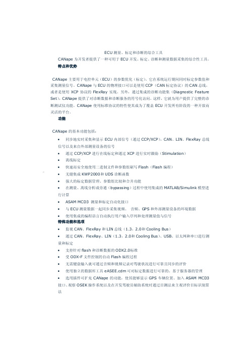
ECU测量、标定和诊断的综合工具CANape为开发者提供了一种可用于ECU开发、标定、诊断和测量数据采集的综合性工具。
特点和优势CANape主要用于电控单元(ECU)的参数优化(标定)。
它在系统运行期间同时标定参数值和采集测量信号。
CANape与ECU的物理接口可以是使用CCP(CAN标定协议)的CAN总线,或者是使用XCP协议的FlexRay实现。
另外,通过集成的诊断功能集(Diagnostic Feature Set),CANape提供了对诊断数据和诊断服务的符号化访问。
这样,它就为用户提供了完整的诊断测试仪功能。
CANape使用标准协议的特性使其成为了覆盖ECU开发所有阶段的一种开放而灵活的平台。
功能CANape的基本功能包括:∙同步地实时采集和显示ECU内部信号(通过CCP/XCP),CAN、LIN、FlexRay总线信号以及来自外部测量设备的信号∙通过CCP/XCP进行在线标定和通过XCP进行实时激励(Stimulation)∙离线标定∙快速而安全地使用二进制文件和参数组刷写Flash(Flash编程)∙无缝集成KWP2000和UDS诊断函数∙强大的标定数据管理、参数组比较和合并功能∙在测量、离线分析或旁通(bypassing)过程中使用集成的MATLAB/Simulink模型进行计算∙ASAM MCD3 测量和标定自动化接口∙与ECU测量数据一起同步采集视频、音频、GPS和外部测量设备的环境数据∙使用集成的编程语言自动执行用户输入序列和处理测量值与信号特殊功能和选项∙监视CAN、FlexRay和LIN总线(1.3,2.0和Cooling Bus)∙通过CAN、FlexRay、LIN(1.3,2.0和Cooling Bus)、USB、以太网和串口进行测量和标定∙支持针对flash和诊断数据的ODX2.0标准∙受ODX-F文件控制的自动Flash编程过程∙无需键盘输入就可通过音频和视频记录对驾驶状况进行可靠且同步的评价∙使用独立的数据库工具eASEE.cdm可对标定数据进行可靠的、基于服务器的管理∙选用插件可扩充CANape的功能,使其能够显示GPS车辆位置、加入ASAM MCD3接口、观察OSEK操作系统以及在开发驾驶员辅助系统时通过目测法来主观评价目标识别算法使用多种测量、显示和标定窗口的配置实例应用领域CANape是进行ECU标定的综合工具。
快速原型(bypass)使用教程

快速原型的设置与应用
一、软件安装
快速原型(Bypass)功能基于 canape12.0; 在Matlab中安装CANape实时 对象,文档中以2011b版本为例, 下同; CANape实时对象包含在 CANape Matlab集成包中,安装时 需要进行选择; 继续下一步;
四、配置管理
4)编译参数设置,步长可根据实际情况适当调整;
四、配置管理
5)优化设置,勾选Inline parameters;
五、参数获取
在搭建完bypass模型之后,对模型参数与信号进行获取: 1)运行模型测试脚本工具,如右所示; 2)按照2->3->7的顺序获得mpt数据文件; 3)加载模型mpt文件至Workspace中;
mpt文件的信号与参数设置窗口如下: StorageClass属性需改为“Ex数设置窗口
六、模型编译
对搭建完成的bypass模型进行编译,可以通过Ctrl+B实现; 编译后生成的DLL文件在之前设定的文件夹(配置管理步骤3)中; 模型描述文件在<模型名称>_cnp_model文件夹中; 模型代码在<模型名称>_cnp_rtw文件夹中。
七、DLL文件集成
接口变量link设置 DLL被加载入CANape之后,出现右边的 界面,界面中Inputs/Outputs栏中的模型输 入输出尚未与ECU中的实际变量相关联; 点击单个接口变量,在弹出的手动link窗 口中选取ECU程序对应的变量; 依次完成所有接口变量的link设置,得到 如下所示的界面,表示link设置完成; 需要注意的是,测量模式下,模型输入 的采样率与输入信号是保持一致的,如link的 信号是8ms采样周期,则模型输入周期设为 ‘on <ECU name> 8ms’;模型输出周期 则设为‘on <modelname> calculated’。
ECU系统开发工具链ECU System Development Tool Chain
ECU系统开发工具链ECU System Development Tool Chainalen-eyre@ECU 开发V模型 ECU V Model1CRManager2Excel2DBC3CodeFormatter4A2L Compare9 LabelManager10 TimeLineCalc5 INCA Add-on6 AutoCalSystem7 DataAnalyzer8 DCM Compare工具链 Tool Chain编号No. 名称Name描述Description1 CRManager 基于数据库的需求管理Change requirement management based on database2 Excel2DBC CAN DBC生成Create CAN DBC from Excel3 CodeFormatter 自动代码格式化Standardize code format4 A2L Compare A2L模块和系统常数管理A2L function and system constant managment5 INCA Add-on INCA实验环境插件:INCAEnum、INCAMask、INCABitCalINCA Experiment Add-on:INCAEnum、INCAMask、INCABitCal 6 AutoCalSystem 自动测量标定系统Automatic calibration system编号No. 名称Name描述Description7 DataAnalzyer 数据分析:dat、asc等格式Analyze data, support dat\asc format8 DCM Compare 基于Excel的标定数据管理Calibration data management based on Excel9 LabelManager 基于数据库的标定数据管理Calibration data management based on database 10 TimeLineCalc 时间节点计算Time line calculate关键技术 Key Feature⏹常用工具的二次开发,如INCA、PUMA、CAMEO、CANalzyer。
高效易用的汽车控制系统快速原型产品——ControlBase

频率量输入:8 路电压型 磁电式信号输入:2 路 喷油驱动:8 路 高端开关:4 路,2.9A (1) 高端开关:1 路,6.5A (1) 继 电 器 低 端 开 关 : 16 路 , 300mA/500mA (2) 低端开关:6 路,1.1A/0.55A (3)
高端开关:1 路,3.9A
(1) 给出值均为典型电流值
发。
产品功能
z ControlBase 硬件平台
系统 CPU 供电
ControlBase_VT
ControlBase_D
ห้องสมุดไป่ตู้
MCU : MC9S12XEP100 , 主 频 MCU:MPC5554,主频 80MHz,
40MHz,FLASH1MB,RAM64KB, FLASH2MB,SRAM 64KB
EEPROM4KB
CAN:4 路,高速
CAN:3 路,高速
K-Line/LIN:2 路
供电电压:9~32V
供电电压:9~32V
传感器供电:4 路 5V 传感器供电电 传感器供电:4 路 5V 传感器供电
源
电源
电源监控
电源和温度监控
模拟量输入:0-5V 输入,12 位精度, 模拟量输入:0-5V 输入,12 位精
6 路无源传感器输入,7 路有源传感 度,13 路无源传感器输入,13 路
高效易用的汽车控制系统快速原型产品——ControlBase
概述
ControlBase 系列产品的特点在于其汽车级的最小系统、信号处理和功率驱动电路,以 及模块化的基础软件。
作为快速控制原型产品,ControlBase 系列产品通过了符合汽车级标准的环境试验,因 此可以作为产品级控制器来支持后续的台架、实车试验,以及小批量装车。
俊翔:10款主流ECU升级设备功能简介和用途...

俊翔:10款主流ECU升级设备功能简介和用途...不管是做汽车电子维修,还是做刷动力升级,几乎都涉及到读写ECU数据,因为只有拿到ECU数据,才有下一步的可能。
例如:屏蔽尿素、故障码DTC、微粒过滤DPF、数据修复更换、动力改装等都要处理ECU电脑文件。
本文信息量大,约5000字,阅读时间约3分钟。
在介绍ECU电脑读写设备之前,需要说明一点。
所有动力升级设备,都只是一个读写数据的工具,不具有修改数据的功能。
我们只是通过它读出数据,然后对数据进行修改,再写回去。
下面分享常见的正版、国产ECU电脑读写设备,我们把它分两大块。
第一种、正版设备。
正版设备价格比较高,普遍都要两三万以上,正版设备的软件版本能够升级。
但每年都需要缴年费,不交年费就有可能做不了新款车,有些甚至直接不能用,年费普遍都是在4000元以上甚至更高。
年费的意思是设备本身软件升级费用,并不是调教程序的费用。
近几年市面上流行的ECU动力升级设备(正版)都是来自国外。
其实ECU动力设备就是一个专用编程器,专门用来读写发动机ECU数据。
ECU动力升级设备都有一个特点,它们会区分:母机(Master)和子机(Slave),也常称母设备和子设备。
这一点,有些人做ECU动力升级这行几年,都还不一定不清楚。
母机和子机有什么区别?母机和子机外观是一样。
母机我们可以理解成一台能正常使用的设备。
而子机,就是挂靠在一台母机下面,子机的功能和母设备功能是一样,母子能做什么车,子机就能做什么车。
但是呢,子机读出来的数据是加密的,不能用来直接调教程序,需要再经过对应的母机进行解密,才能够对程序进行编辑。
一台母机,可以扩展无限台子机。
这样设计有什么好处?这样的设计可以很好的组建自己团队。
例如,你手上有一台母机,你就可以招募你的分代理商,给代理商提供子机。
子机价格会比母机便宜一半以上,但子机读出来的程序,必须通过你上家的母机解码,才能再进行调效。
可以防止你的下线子机不通过你,私自发给别人调教,保护自己市场。
ETAS ECU开发快速原型介绍
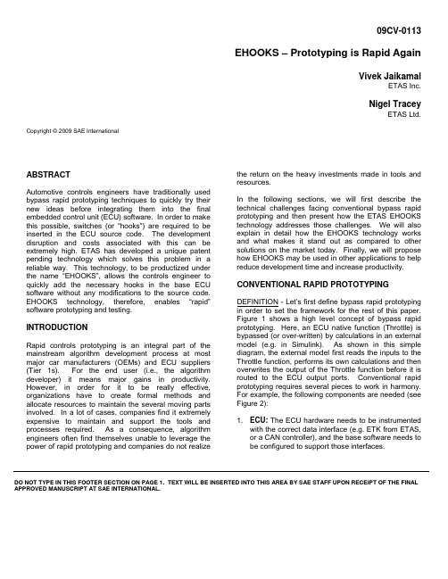
DO NOT TYPE IN THIS FOOTER SECTION ON PAGE 1. TEXT WILL BE INSERTED INTO THIS AREA BY SAE STAFF UPON RECEIPT OF THE FINAL APPROVED MANUSCRIPT AT SAE INTERNATIONAL.09CV-0113EHOOKS – Prototyping is Rapid AgainVivek JaikamalETAS Inc.Nigel TraceyETAS Ltd.Copyright © 2009 SAE InternationalABSTRACTAutomotive controls engineers have traditionally used bypass rapid prototyping techniques to quickly try their new ideas before integrating them into the final embedded control unit (ECU) software. In order to make this possible, switches (or “hooks”) are required to be inserted in the ECU source code. The development disruption and costs associated with this can be extremely high. ETAS has developed a unique patent pending technology which solves this problem in a reliable way. This technology, to be productized under the name “EHOOKS”, allows the controls engineer to quickly add the necessary hooks in the base ECU software without any modifications to the source code. EHOOKS technology, therefore, enables “rapid” software prototyping and testing.INTRODUCTIONRapid controls prototyping is an integral part of the mainstream algorithm development process at most major car manufacturers (OEMs) and ECU suppliers (Tier 1s). For the end user (i.e., the algorithm developer) it means major gains in productivity. However, in order for it to be really effective, organizations have to create formal methods and allocate resources to maintain the several moving parts involved. In a lot of cases, companies find it extremely expensive to maintain and support the tools and processes required. As a consequence, algorithm engineers often find themselves unable to leverage the power of rapid prototyping and companies do not realize the return on the heavy investments made in tools and resources.In the following sections, we will first describe the technical challenges facing conventional bypass rapid prototyping and then present how the ETAS EHOOKS technology addresses those challenges. We will also explain in detail how the EHOOKS technology works and what makes it stand out as compared to other solutions on the market today. Finally, we will propose how EHOOKS may be used in other applications to help reduce development time and increase productivity.CONVENTIONAL RAPID PROTOTYPINGDEFINITION - Let’s first define bypass rapid prototyping in order to set the framework for the rest of this paper. Figure 1 shows a high level concept of bypass rapid prototyping. Here, an ECU native function (Throttle) is bypassed (or over-written) by calculations in an external model (e.g. in Simulink). As shown in this simple diagram, the external model first reads the inputs to the Throttle function, performs its own calculations and then overwrites the output of the Throttle function before it is routed to the ECU output ports. Conventional rapid prototyping requires several pieces to work in harmony. For example, the following components are needed (see Figure 2):1. ECU: The ECU hardware needs to be instrumentedwith the correct data interface (e.g. ETK from ETAS, or a CAN controller), and the base software needs to be configured to support those interfaces.2. Prototyping Hooks: The ECU function or variablethat will be bypassed needs to have a “hook”implemented that allows the software to switch between its internal value and that calculated by the bypass function. It also allows the user to control which value is used.Figure 1: Schematic of Bypass Rapid Prototyping3. External Processor: Usually the bypass function isexecuted on an external processor that is more powerful than the ECU’s microprocessor.4. The data interface: The data interface between theECU and the external processor is crucial for the real-time performance of the bypass system.5. Software Services: Support services in the ECUsoftware are needed to manage the efficient transport of data to/from the external processor.These services also monitor the health of the data link, and abort bypass if the link is broken.6. Trigger Mechanism: In order for the bypassfunction to run synchronously with the timer and event based tasks of the real-time operating system (RTOS) implemented in the ECU, a trigger mechanism needs to be in place. This allows the ECU microprocessor to be the master scheduler, and the external processor to be the slave.7. Configuration Tool: The PC application that allowsthe new control algorithms to be mapped to the bypass hooks in the ECU base software, compile and execute the algorithms in the external processor, and manage/control the experiment in real-time.Typically, an ECU tool vendor provides some of the pieces above, while the Tier 1 supplier or OEM provides the rest. There is an initial integration phase where the software services, hooks, interfaces and tools are tested to conform to the targeted development process. After this is done, the tools are made available for thealgorithm engineer to use.Figure 2: Typical System Components EXAMPLES OF HOOKS – The usefulness and application of hooks (or switches) is determined by their location relative to an ECU function of interest. For example, for rapid prototyping, a hook is typically placed after an internal ECU function calculation is complete (Figure 3). Thus the ECU calculated value is overwritten by a different value. Bypass rapid prototyping relies onhooks of this type to allow testing of new algorithms.Figure 3: A Rapid Prototyping HookIf the hook is placed at the input of the ECU function, however, it represents a different application (Figure 4). Test and validation engineers may use hooks of this type to test the robustness of the ECU function in the presence of input variability. Design engineers, on theother hand, find it useful to test new sensor designs withexisting ECU software.Figure 4: A Test and Validation HookHooks may also be placed to re-write any ECU variable located in RAM with a calibration parameter that may be adjusted during run-time (Figure 5). Such hooks are useful when you need to fix a certain ECU value in order to focus on behavior observed downstream or isolate problems one by one. Calibration and diagnosticengineers find such hooks to be especially useful.Figure 5: Calibration and Diagnostics HooksEHOOKS TECHNOLOGYIn the conventional framework described above, new control algorithms invariably require new software hooks to be placed in the base software. This task is arduous, expensive and causes significant development disruption – taking the rapid out of rapid prototyping! EHOOKS enables the end user to place all necessary hooks without the hassle of making changes to the base software. EHOOKS does this in the following way. PREPARATION PHASE – An essential element of EHOOKS technology is the Preparation Tool. This software tool allows the initial one-time preparation of the ECU base software (e.g., by the Tier 1 supplier). It also captures and stores the following information inside an encrypted block in the ASAM-MCD-2MC (or A2L) file:• Memory information – e.g. ROM and RAM for theaddition of user functions and bypass hooks.• Information regarding the ECU software architecture(e.g., the structure of global and local variables, update rate of key variables etc.)• ECU variables and functions that may be bypassedby the end user. Software suppliers can use this feature to protect certain areas of their software (e.g. key input/output and diagnostic functions) from being overwritten unintentionally by the end user. • ECU variables and functions that can be utilized bythe bypass functions (e.g., math libraries, internal sensor values etc.)• ECU RTOS tasks and function containers that maybe used to execute bypass models.In addition, this phase disables the ECU checksums (which might otherwise cause the ECU to shut down) and adds certain EHOOKS support functions and administrative calibrations/variables to the base software. Through this process, EHOOKS ensures that the subsequent hook installation phase results in a robust and reliable ECU image.HOOK INSTALLATION PHASE – The second tool (called the EHOOKS Hook Insertion Tool) exploits the information stored in the A2L file by the Preparation Tool and uses it to configure and install the bypass hooks into the base HEX file. It does this in several steps:• First, the user selects (from the A2L file) whichvariables in the base software will be bypassed, and with which type of hooks (e.g. constant, calibration, external, internal). EHOOKS also allows a copy of the original ECU value to be created for comparison purposes. Example dialogs are shown in Figures 6 and 7. Both replacement and offset modes of bypass are supported (Figure 8).Figure 6: Selection dialog for Installing Hooks• The Installation Tool then locates the writeinstructions to these variables in the base HEX file. As part of EHOOKS technology, ETAS hasdeveloped an instruction set simulator (ISS) that allows these write instructions to be correctly locatedeven in the presence of complex address calculations (Figure 9).•Once the writes are located, the Hook Insertion Tool patches those locations with jump instructions to reserved memory areas where special hook-code is inserted (Figure 9).•The hook control parameters are also added to the calibration memory of the ECU (e.g. the Enable parameter for each hook in Figure 8).•User provided code for bypass functions is compiled by EHOOKS, which then generates the necessary link script to ensure the code (and its data) are located within the ECU memory sections reserved for use by EHOOKS as described in the encrypted section of the A2L file.•During each build EHOOKS checks to ensure the available ECU resources reserved for EHOOKS use are sufficient for the specific configuration. If not, the build is halted with an error.•The A2L file is updated with all the necessary hook control parametersFigure 7: Selection of Hook PropertiesFigure 8: Bypass Modes supported by EHOOKSThe user can now rewrite the ECU memory with the new HEX file using standard flashing and/or debugging tools or calibration tools that support flashing (e.g. ETAS INCA software). The new A2L file may be used by standard calibration tools for accessing and controlling the operation of the hooks during run-time.Figure 9: The original and patched ECU imagesTYPES OF HOOKS – With EHOOKS, several types of hooks may be inserted in the original ECU software image, enabling several different use cases.1. Constant Value Hooks (Figure 10) are useful whenyou need to fix an ECU RAM variable to a constant value (e.g. to simulate a faulty sensor). Once fixed, the value cannot be changed during run-time. It has to be changed by the EHOOKS Installation Tool anda new software image has to be flashed to the ECU.Figure 10: A Constant Value Hook2. Calibration Hooks (Figure 11) are useful when youneed to control the value of an ECU RAM variable during run-time using a standard calibration tool (e.g., INCA from ETAS). The calibration parameter is automatically added to the A2L file by theEHOOKS Installation Tool.Figure 11: A Calibration Value Hook3. Internal Bypass Hooks (Figure 12) allow an ECURAM variable to be overwritten by an algorithm running directly on the ECU. This methodology, commonly known as on-target prototyping, is very useful when the ECU has spare resources (ROM,RAM, task-time) available to run new algorithms.Figure 12: Internal Bypass Hooks4. External Bypass Hooks (Figure 13) allow traditionalbypass rapid prototyping using an external processor. Bypass algorithms may be developed in model-based tools such as ASCET from ETAS or Simulink from The Mathworks, or directly in C-code. EHOOKS only configures the hooks in the ECU image to accept values written by an external target, independent of which external target or modeling language is actually used.EHOOKS, therefore, provides a completely scalable solution for a wide variety of applications – starting from simple calibration use cases (that require minimum additional ECU resources) to on-target and externalrapid prototyping.Figure 13: External Bypass HooksThe technology leverages proprietary ECU internal information encrypted and stored in the A2L file by the Tier 1 supplier. This allows EHOOKS to not only reliably detect all write instances of a RAM variable, but also institute run-time safety detection mechanisms that alert the user to potential data inconsistencies during run-time. In addition, the hook code inserted by EHOOKS includes the code from the original ECU software such that, if the hook is disabled, the original ECU software functionality is restored.ADVANCED APPLICATIONSIn addition to the use cases described above, EHOOKS technology may be applied to solve a myriad of advanced problems related to software development and validation. Some of these are described below.1. Disabling an ECU process: The order of executionof processes inside an ECU task is pre-defined andnormally cannot be altered by the user.Figure 14: Disabling an ECU processThe encrypted A2L block created by the EHOOKS Preparation Tool allows the Tier 1 supplier to securely provide the process list to the EHOOKS Installation Tool, which then allows the user to select and control the execution of specific processes (Figure 14). This feature is useful, for example, when:•An entire ECU function has to be bypassed. By disabling the whole process, significant CPU resources can be freed-up for a new algorithm, or• An errant ECU process is preventingdownstream processes from functioning properly, or is paralyzing the ECU.2. Scheduling of on-target algorithms: EHOOKSprovides the flexibility to leverage existing ECU resources in the best way possible. One way to do this is to allow user code for on-target algorithms to run within a dedicated process created solely for that purpose. These processes are known as “bypass containers” (Figure 15). The actual software hook may reside in a different (e.g. faster) process, but due to bandwidth limitations it may be not be possible to execute the new algorithm in the same task. In many cases, it is still be acceptable to run the new algorithm in a slower task in order to check its validity. The EHOOKS Hook Insertion Tool (optionally) allows the user to pick the bypass container from an available list of processes, andassign the algorithm to it.Figure 15: Bypass Container Process3. Function in the Loop (FiL): In a traditional hardware-in-the-loop (HiL) setup (Figure 16), the ECU is connected via an electrical harness to a HiL system that runs a vehicle system model in real-time and generates the necessary sensor signals (e.g., crank, cam, wheel speeds). The sensor signals are identical to those available on a real vehicle and are passed to the ECU via the electrical harness. In return, the actuator signals computed by the ECU software are sent back over the harness to the HiL system, where electrical or simulated loads are used to emulate the conditions found on the vehicle. This process requires extensive signal conditioning on the HiL system in order to convert physical values (e.g. temp in deg F, speed in m/s) to electrical values (e.g. voltage) and vice-versa.Figure 16: A conventional HiL system setupFigure 17: A Function-in-the-Loop SystemAlthough HiL systems come close to simulating the environment of an ECU, there are significant costs involved in building the signal conditioning hardware necessary for proper operation. In the recent past, the FiL methodology has emerged as a way to overcome these challenges of HiL and reap some of the same benefits. With FiL (Figure 17), the expensive signal conditioning and load hardware is avoided. The plant model running on a real-time PC(e.g. the ETAS LABCAR-RTPC) generates sensorsignals that are copied directly to the ECU memory.Similarly, the actuator commands are read directly from the ECU memory and connected to back to the plant model. This direct exchange of software signals is made possible via a memory emulator probe (e.g. the ETAS ETK device) mounted on the ECU. Since the electrical interfaces of the ECU are idle, it is necessary to disable diagnostic functions in the ECU software for FiL to work.EHOOKS technology is used to install the necessary software hooks for FiL – e.g., to overwrite an ECU memory location that is normally used to store a sensor value calculated by the ECU.CASE STUDIESAt the time of writing, ETAS is in the final stages of releasing the EHOOKS product to the market. However, the technology has already been proven and refined through select lead customer projects over the last eighteen months. Some key examples of customer projects are presented below.•In Asia, a major OEM is using EHOOKS for accelerating the development of new ECU functions via traditional rapid prototyping. They are now able to avoid the cost (typically €10k - €30k) of each new software change request for new hooks charged by their Tier 1 supplier. They are also able to reduce the number of ECU software releases required before start of production by about 50%.•In Europe, a major OEM is reporting that by using EHOOKS they are able to create a new software version in about 5 minutes, when it previously took them anywhere from one to eight weeks.•In Europe, another major OEM’s Tier1 supplier is unable to manually add hooks to the software because they don’t have access to certain sections of the code. In this situation, the only option for the OEM is to use EHOOKS to add the necessary bypass hooks.• A FiL system developed by ETAS jointly with a leading European Tier 1 supplier is in use for software development, system integration and testing. CONCLUSIONIn this paper, we have presented a new patent-pending technology from ETAS that inserts software hooks and code into an existing ECU software image without the need for the source code. This technology allows the software vendor (Tier 1) to securely share proprietary ECU architecture and implementation details (necessaryto make EHOOKS flexible and robust), without exposing their core intellectual property to the OEMs. Using this technology, controls engineers can once again “rapidly” develop and test new strategies either directly on the ECU (if there is enough memory and processor bandwidth available) or on an external rapid prototyping system (such as the ETAS ES910) without incurring the cost and delays associated with traditional software hooks.ACKNOWLEDGMENTSWe wish to acknowledge the tireless efforts and innovative spirit of the entire EHOOKS development and product management team at ETAS. In addition, thanks go to several lead customers who provided invaluable input and feedback to help ETAS refine the technology.REFERENCES1. Gebhard, M.; Lauff, U.; Schnellbacher, K.: Operationam offenen Herzen – Entwicklung und Test von Steuergerätefunktionen mit der Bypass-Methode, Elektronik Automotive 2008, Issue 6, Pg. 34-39.2. Dubitzky, W.; Eismann, W; Schinagl, J.:Einsatzmöglichkeiten der Bypass-Methode für Entwicklung und Test von Steuergerätefunktionen,Electronik Automotive 2008, Issue 8, Pg. 52-56.3. Triess, B.; Müller, C; Lauff, U.; Mößner C.:Entwicklung und Applikation von Motor- und Getriebesteuerungen mit der ETK-Steuergeräteschnittstelle. ATZ AutomobiltechnischeZeitschrift 109 (2007), Issue 1, Pg. 32-39.4. INCA, ASCET, LABCAR-RTPC, ETK and otherETAS products: 5. ASAM-MCD-2MC, CONTACTVivek Jaikamal is a Marketing Manager for software engineering tools at ETAS, Inc. in Ann Arbor, MI. He can be reached via email at vivek.jaikamal@ Nigel J. Tracey is a Product Manager for ETAS embedded software tools based out of York, UK. He may be reached via email at nigel.tracey@。
ETASECU开发快速原型介绍

ETASECU开发快速原型介绍ETASECU开发快速原型解决方案包括硬件和软件两个部分。
硬件方面,ETAS提供了无风扇的高性能计算平台以及各种接口模块和扩展板,以支持不同类型的ECU。
软件方面,ETAS提供了一套强大的工具链,包括ECU仿真器、模型开发环境和调试工具等。
首先,ETASECU开发快速原型解决方案允许开发人员在尚未买下实际硬件之前,使用仿真器来执行ECU软件。
这使得开发人员能够在硬件可用之前验证和修复软件问题,以提高开发效率。
其次,ETAS ECU开发快速原型解决方案支持使用模型开发环境来设计和验证ECU功能。
开发人员可以使用MATLAB / Simulink等流行的建模和仿真工具,创建ECU功能模型并将其部署到ETAS计算平台上进行测试和验证。
这种基于模型的开发方法可以大大减少编写和调试底层代码的时间,加快开发速度。
另外,ETASECU开发快速原型解决方案还提供了强大的调试工具,帮助开发人员在ECU开发过程中快速定位和解决问题。
这些调试工具包括实时追踪、变量监视和事件跟踪等功能,使开发人员能够深入了解ECU的运行状况并进行必要的优化。
此外,ETASECU开发快速原型解决方案还具有高度可扩展性。
开发人员可以使用各种接口模块和扩展板,将ETAS计算平台与真实的ECU硬件进行连接,以便进行更精确的测试和验证。
这种可扩展性使得ETASECU开发快速原型解决方案可以适用于各种类型和规模的ECU开发项目。
总之,ETASECU开发快速原型解决方案是一种高效的ECU开发工具,通过提供仿真器、模型开发环境和调试工具等功能,帮助开发人员快速设计、模拟和验证ECU的功能和性能。
它的优势在于能够在硬件可用之前进行软件验证、支持基于模型的开发方法、提供强大的调试功能以及具有高度可扩展性。
这些特点使得ETASECU开发快速原型成为现代ECU开发过程中不可或缺的工具。
ControlBase——基于全自动代码生成的ECU快速开发解决方案
ControlBase — 基于全自动代码生成的ECU快速开发解决方案“使用ControlBase可以缩短50%开发周期,降低80%开发成本。
”“ControlBase不仅是快速原型工具,还是全自动代码生成工具。
”“全自动代码生成技术可以削减80%的控制器软件开发工作量。
”控制器快速原型可以在没有控制器硬件的情况下,提前进行控制算法的开发与验证,尤其适合于新产品、新型号的开发研究,快速原型可以在一定程度上缩短开发周期,降低开发成本。
由于快速原型仅仅是对控制算法进行了验证,在控制器开发的整个过程中,除了开发控制算法以外,还需要开发硬件与各类基础软件(包括底层驱动、标定协议、引导加载程序、实时操作系统、通信协议栈等等),之后还需要将基础软件与应用软件(包括控制算法与诊断算法)进行手工集成,工作量巨大,过程漫长。
从整个开发过程的角度来看,快速原型所起的作用比较有限。
全自动代码生成在应用软件代码自动生成的基础上进一步发展,自动生成基础软件代码,从而实现整个控制器软件的自动代码生成,大幅削减控制器软件开发的工作量。
ControlBase提供了基于全自动代码生成的ECU快速开发解决方案。
当作为快速原型工具使用时,ControlBase为常用电控系统控制算法提供一个快速验证的平台,既可用于实验室测试也可用于装车试验。
当作为全自动代码生成工具使用时,ControlBase支持基础软件与应用软件的自动代码生成,削减了控制器软件开发的工作量。
作为产品级原型硬件,ControlBase为控制器硬件设计提供参考,降低硬件返工几率。
在控制器开发的整个过程中,使用ControlBase可以缩短开发周期,降低开发成本,提高控制器设计质量。
在控制器快速原型阶段,ControlBase适合于发动机ECU、自动变速器TCU、混合动力HCU、电动汽车VCU、防抱死制动系统ABS等常用汽车电控系统控制器的快速原型,为常用电控系统控制算法提供一个快速验证的平台,可以支持硬件在环测试、台架试验和实车试验。
快速原型(bypass)使用教程
二、模块介绍
2)Output模块:作用是向CANape传输模型计算值;
双击模块,弹出如下参数设置窗口,同样可以对输 入信号进行设置,其中Symbolic name可以填写具 体数字或者变量名,变量名即传递到CANape中的 变量名,需保证CANape中有对应的变量。
一、软件安装
安装完成后,打开Matlab Simulink; 在左侧目录中新增了bypass相关的条目,表示相关的功能模块安装成功。
二、模块介绍
在bypass模型中,除了常用的Simulink模块以外,还包含了与CANape交互的输
入输出接口,主要包含了以下两个模块:
1)Input模块:作用是从CANape中获取对应参数的值;
四、配置管理
4)编译参数设置,步长可根据实际情况适当调整;
四、配置管理
5)优化设置,勾选Inline parameters;
五、参数获取
在搭建完bypass模型之后,对模型参数与信号进行获取: 1)运行模型测试脚本工具,如右所示; 2)按照2->3->7的顺序获得mpt数据文件; 3)加载模型mpt文件至Workspace中;
设置完成
八、Device设置
Device设置 点击配置界面的Create device;
八、Device设置
Device设置 选择编译的a2l文件及其路径; 点击下一步;
八、Device设置
Device设置 在MAP文件设置界面,选择MAP file(s) predetermined; 点击new;
MotoTron+ECU快速开发平台
MotoTron ECU快速开发平台MotoTron ECU R&D Platform控制代码通过CAN进行刷写,高速、可靠所有的ROM 和RAM 参量均可以工程单位显示能同时连接多个ECU ,单个ECU 可以连接多个应用程序完善的在线帮助系统,用户可自定义快捷键界面友好,操作简便易用主要特性:MotoTune -ECU 调试工具通过使用MotoHawk 完成控制算法的规格定义和功能设计之后,使用MotoTune 用户可将软件策略针对相应硬件ECU 自动生成可执行性代码,并通过专业的调试工具,将其刷写到ECU 中,并能够进行一些底层的调试。
MotoTune 标定工具能够实现各种典型的调试功能,而且其界面直观友好,用户可以很容易地获得ECU 中RAM 和ROM 内的每个相关参数,并对其进行分析、调节或修改。
DEV ECU-MotoTron 开发ECU根据不同的应用范围,MotoTron 可以提供24针、48针、80针、112针和128针不同的ECU 硬件选择,微处理器包括:16位HCS12, 32位MPC5XX 和MPC55XX 。
对于用户已有的以其它处理器为核心的ECU ,MotoTron 也可以提供控制策略移植的支持服务。
MotoTron 开发平台硬件均是由Continental 公司生产并且可以批量供应的产品级ECU ,因此将快速原型开发阶段和产品化阶段可以无缝地结合起来。
这些产品级的MotoTron 开发平台硬件具有耐久性和完全密封性的特点,能够在一些极限的工作环境条件下正常工作。
完全适用于汽车、商用车、船舶和工程应用领域。
同时,对于需要采购大量原型开发系统硬件进行批量路试或者台架试验的客户来讲,MotoTron 具有非常大的价格优势,目前世界上已有超过100万套的MotoTron 硬件ECU-555-8080 pins-MPC555ECU-5554-112112 pins-MPC5554ECU-565-128128 pins-MPC565PIM-5554-60New Product概念设计SCR 硬件评估和供应集成和设计工作传感器定义以及ECU 匹配新的ECU 功能开发发动机标定SCR 优化变速箱控制系统快速开发平台基于MotoTron 的变速箱控制系统开发平台是一套理想的开发AMT, CVT, DCT 等控制系统的解决方案。
ETAS ECU开发快速原型介绍
DO NOT TYPE IN THIS FOOTER SECTION ON PAGE 1. TEXT WILL BE INSERTED INTO THIS AREA BY SAE STAFF UPON RECEIPT OF THE FINAL APPROVED MANUSCRIPT AT SAE INTERNATIONAL.09CV-0113EHOOKS – Prototyping is Rapid AgainVivek JaikamalETAS Inc.Nigel TraceyETAS Ltd.Copyright © 2009 SAE InternationalABSTRACTAutomotive controls engineers have traditionally used bypass rapid prototyping techniques to quickly try their new ideas before integrating them into the final embedded control unit (ECU) software. In order to make this possible, switches (or “hooks”) are required to be inserted in the ECU source code. The development disruption and costs associated with this can be extremely high. ETAS has developed a unique patent pending technology which solves this problem in a reliable way. This technology, to be productized under the name “EHOOKS”, allows the controls engineer to quickly add the necessary hooks in the base ECU software without any modifications to the source code. EHOOKS technology, therefore, enables “rapid” software prototyping and testing.INTRODUCTIONRapid controls prototyping is an integral part of the mainstream algorithm development process at most major car manufacturers (OEMs) and ECU suppliers (Tier 1s). For the end user (i.e., the algorithm developer) it means major gains in productivity. However, in order for it to be really effective, organizations have to create formal methods and allocate resources to maintain the several moving parts involved. In a lot of cases, companies find it extremely expensive to maintain and support the tools and processes required. As a consequence, algorithm engineers often find themselves unable to leverage the power of rapid prototyping and companies do not realize the return on the heavy investments made in tools and resources.In the following sections, we will first describe the technical challenges facing conventional bypass rapid prototyping and then present how the ETAS EHOOKS technology addresses those challenges. We will also explain in detail how the EHOOKS technology works and what makes it stand out as compared to other solutions on the market today. Finally, we will propose how EHOOKS may be used in other applications to help reduce development time and increase productivity.CONVENTIONAL RAPID PROTOTYPINGDEFINITION - Let’s first define bypass rapid prototyping in order to set the framework for the rest of this paper. Figure 1 shows a high level concept of bypass rapid prototyping. Here, an ECU native function (Throttle) is bypassed (or over-written) by calculations in an external model (e.g. in Simulink). As shown in this simple diagram, the external model first reads the inputs to the Throttle function, performs its own calculations and then overwrites the output of the Throttle function before it is routed to the ECU output ports. Conventional rapid prototyping requires several pieces to work in harmony. For example, the following components are needed (see Figure 2):1. ECU: The ECU hardware needs to be instrumentedwith the correct data interface (e.g. ETK from ETAS, or a CAN controller), and the base software needs to be configured to support those interfaces.2. Prototyping Hooks: The ECU function or variablethat will be bypassed needs to have a “hook”implemented that allows the software to switch between its internal value and that calculated by the bypass function. It also allows the user to control which value is used.Figure 1: Schematic of Bypass Rapid Prototyping3. External Processor: Usually the bypass function isexecuted on an external processor that is more powerful than the ECU’s microprocessor.4. The data interface: The data interface between theECU and the external processor is crucial for the real-time performance of the bypass system.5. Software Services: Support services in the ECUsoftware are needed to manage the efficient transport of data to/from the external processor.These services also monitor the health of the data link, and abort bypass if the link is broken.6. Trigger Mechanism: In order for the bypassfunction to run synchronously with the timer and event based tasks of the real-time operating system (RTOS) implemented in the ECU, a trigger mechanism needs to be in place. This allows the ECU microprocessor to be the master scheduler, and the external processor to be the slave.7. Configuration Tool: The PC application that allowsthe new control algorithms to be mapped to the bypass hooks in the ECU base software, compile and execute the algorithms in the external processor, and manage/control the experiment in real-time.Typically, an ECU tool vendor provides some of the pieces above, while the Tier 1 supplier or OEM provides the rest. There is an initial integration phase where the software services, hooks, interfaces and tools are tested to conform to the targeted development process. After this is done, the tools are made available for thealgorithm engineer to use.Figure 2: Typical System Components EXAMPLES OF HOOKS – The usefulness and application of hooks (or switches) is determined by their location relative to an ECU function of interest. For example, for rapid prototyping, a hook is typically placed after an internal ECU function calculation is complete (Figure 3). Thus the ECU calculated value is overwritten by a different value. Bypass rapid prototyping relies onhooks of this type to allow testing of new algorithms.Figure 3: A Rapid Prototyping HookIf the hook is placed at the input of the ECU function, however, it represents a different application (Figure 4). Test and validation engineers may use hooks of this type to test the robustness of the ECU function in the presence of input variability. Design engineers, on theother hand, find it useful to test new sensor designs withexisting ECU software.Figure 4: A Test and Validation HookHooks may also be placed to re-write any ECU variable located in RAM with a calibration parameter that may be adjusted during run-time (Figure 5). Such hooks are useful when you need to fix a certain ECU value in order to focus on behavior observed downstream or isolate problems one by one. Calibration and diagnosticengineers find such hooks to be especially useful.Figure 5: Calibration and Diagnostics HooksEHOOKS TECHNOLOGYIn the conventional framework described above, new control algorithms invariably require new software hooks to be placed in the base software. This task is arduous, expensive and causes significant development disruption – taking the rapid out of rapid prototyping! EHOOKS enables the end user to place all necessary hooks without the hassle of making changes to the base software. EHOOKS does this in the following way. PREPARATION PHASE – An essential element of EHOOKS technology is the Preparation Tool. This software tool allows the initial one-time preparation of the ECU base software (e.g., by the Tier 1 supplier). It also captures and stores the following information inside an encrypted block in the ASAM-MCD-2MC (or A2L) file:• Memory information – e.g. ROM and RAM for theaddition of user functions and bypass hooks.• Information regarding the ECU software architecture(e.g., the structure of global and local variables, update rate of key variables etc.)• ECU variables and functions that may be bypassedby the end user. Software suppliers can use this feature to protect certain areas of their software (e.g. key input/output and diagnostic functions) from being overwritten unintentionally by the end user. • ECU variables and functions that can be utilized bythe bypass functions (e.g., math libraries, internal sensor values etc.)• ECU RTOS tasks and function containers that maybe used to execute bypass models.In addition, this phase disables the ECU checksums (which might otherwise cause the ECU to shut down) and adds certain EHOOKS support functions and administrative calibrations/variables to the base software. Through this process, EHOOKS ensures that the subsequent hook installation phase results in a robust and reliable ECU image.HOOK INSTALLATION PHASE – The second tool (called the EHOOKS Hook Insertion Tool) exploits the information stored in the A2L file by the Preparation Tool and uses it to configure and install the bypass hooks into the base HEX file. It does this in several steps:• First, the user selects (from the A2L file) whichvariables in the base software will be bypassed, and with which type of hooks (e.g. constant, calibration, external, internal). EHOOKS also allows a copy of the original ECU value to be created for comparison purposes. Example dialogs are shown in Figures 6 and 7. Both replacement and offset modes of bypass are supported (Figure 8).Figure 6: Selection dialog for Installing Hooks• The Installation Tool then locates the writeinstructions to these variables in the base HEX file. As part of EHOOKS technology, ETAS hasdeveloped an instruction set simulator (ISS) that allows these write instructions to be correctly locatedeven in the presence of complex address calculations (Figure 9).•Once the writes are located, the Hook Insertion Tool patches those locations with jump instructions to reserved memory areas where special hook-code is inserted (Figure 9).•The hook control parameters are also added to the calibration memory of the ECU (e.g. the Enable parameter for each hook in Figure 8).•User provided code for bypass functions is compiled by EHOOKS, which then generates the necessary link script to ensure the code (and its data) are located within the ECU memory sections reserved for use by EHOOKS as described in the encrypted section of the A2L file.•During each build EHOOKS checks to ensure the available ECU resources reserved for EHOOKS use are sufficient for the specific configuration. If not, the build is halted with an error.•The A2L file is updated with all the necessary hook control parametersFigure 7: Selection of Hook PropertiesFigure 8: Bypass Modes supported by EHOOKSThe user can now rewrite the ECU memory with the new HEX file using standard flashing and/or debugging tools or calibration tools that support flashing (e.g. ETAS INCA software). The new A2L file may be used by standard calibration tools for accessing and controlling the operation of the hooks during run-time.Figure 9: The original and patched ECU imagesTYPES OF HOOKS – With EHOOKS, several types of hooks may be inserted in the original ECU software image, enabling several different use cases.1. Constant Value Hooks (Figure 10) are useful whenyou need to fix an ECU RAM variable to a constant value (e.g. to simulate a faulty sensor). Once fixed, the value cannot be changed during run-time. It has to be changed by the EHOOKS Installation Tool anda new software image has to be flashed to the ECU.Figure 10: A Constant Value Hook2. Calibration Hooks (Figure 11) are useful when youneed to control the value of an ECU RAM variable during run-time using a standard calibration tool (e.g., INCA from ETAS). The calibration parameter is automatically added to the A2L file by theEHOOKS Installation Tool.Figure 11: A Calibration Value Hook3. Internal Bypass Hooks (Figure 12) allow an ECURAM variable to be overwritten by an algorithm running directly on the ECU. This methodology, commonly known as on-target prototyping, is very useful when the ECU has spare resources (ROM,RAM, task-time) available to run new algorithms.Figure 12: Internal Bypass Hooks4. External Bypass Hooks (Figure 13) allow traditionalbypass rapid prototyping using an external processor. Bypass algorithms may be developed in model-based tools such as ASCET from ETAS or Simulink from The Mathworks, or directly in C-code. EHOOKS only configures the hooks in the ECU image to accept values written by an external target, independent of which external target or modeling language is actually used.EHOOKS, therefore, provides a completely scalable solution for a wide variety of applications – starting from simple calibration use cases (that require minimum additional ECU resources) to on-target and externalrapid prototyping.Figure 13: External Bypass HooksThe technology leverages proprietary ECU internal information encrypted and stored in the A2L file by the Tier 1 supplier. This allows EHOOKS to not only reliably detect all write instances of a RAM variable, but also institute run-time safety detection mechanisms that alert the user to potential data inconsistencies during run-time. In addition, the hook code inserted by EHOOKS includes the code from the original ECU software such that, if the hook is disabled, the original ECU software functionality is restored.ADVANCED APPLICATIONSIn addition to the use cases described above, EHOOKS technology may be applied to solve a myriad of advanced problems related to software development and validation. Some of these are described below.1. Disabling an ECU process: The order of executionof processes inside an ECU task is pre-defined andnormally cannot be altered by the user.Figure 14: Disabling an ECU processThe encrypted A2L block created by the EHOOKS Preparation Tool allows the Tier 1 supplier to securely provide the process list to the EHOOKS Installation Tool, which then allows the user to select and control the execution of specific processes (Figure 14). This feature is useful, for example, when:•An entire ECU function has to be bypassed. By disabling the whole process, significant CPU resources can be freed-up for a new algorithm, or• An errant ECU process is preventingdownstream processes from functioning properly, or is paralyzing the ECU.2. Scheduling of on-target algorithms: EHOOKSprovides the flexibility to leverage existing ECU resources in the best way possible. One way to do this is to allow user code for on-target algorithms to run within a dedicated process created solely for that purpose. These processes are known as “bypass containers” (Figure 15). The actual software hook may reside in a different (e.g. faster) process, but due to bandwidth limitations it may be not be possible to execute the new algorithm in the same task. In many cases, it is still be acceptable to run the new algorithm in a slower task in order to check its validity. The EHOOKS Hook Insertion Tool (optionally) allows the user to pick the bypass container from an available list of processes, andassign the algorithm to it.Figure 15: Bypass Container Process3. Function in the Loop (FiL): In a traditional hardware-in-the-loop (HiL) setup (Figure 16), the ECU is connected via an electrical harness to a HiL system that runs a vehicle system model in real-time and generates the necessary sensor signals (e.g., crank, cam, wheel speeds). The sensor signals are identical to those available on a real vehicle and are passed to the ECU via the electrical harness. In return, the actuator signals computed by the ECU software are sent back over the harness to the HiL system, where electrical or simulated loads are used to emulate the conditions found on the vehicle. This process requires extensive signal conditioning on the HiL system in order to convert physical values (e.g. temp in deg F, speed in m/s) to electrical values (e.g. voltage) and vice-versa.Figure 16: A conventional HiL system setupFigure 17: A Function-in-the-Loop SystemAlthough HiL systems come close to simulating the environment of an ECU, there are significant costs involved in building the signal conditioning hardware necessary for proper operation. In the recent past, the FiL methodology has emerged as a way to overcome these challenges of HiL and reap some of the same benefits. With FiL (Figure 17), the expensive signal conditioning and load hardware is avoided. The plant model running on a real-time PC(e.g. the ETAS LABCAR-RTPC) generates sensorsignals that are copied directly to the ECU memory.Similarly, the actuator commands are read directly from the ECU memory and connected to back to the plant model. This direct exchange of software signals is made possible via a memory emulator probe (e.g. the ETAS ETK device) mounted on the ECU. Since the electrical interfaces of the ECU are idle, it is necessary to disable diagnostic functions in the ECU software for FiL to work.EHOOKS technology is used to install the necessary software hooks for FiL – e.g., to overwrite an ECU memory location that is normally used to store a sensor value calculated by the ECU.CASE STUDIESAt the time of writing, ETAS is in the final stages of releasing the EHOOKS product to the market. However, the technology has already been proven and refined through select lead customer projects over the last eighteen months. Some key examples of customer projects are presented below.•In Asia, a major OEM is using EHOOKS for accelerating the development of new ECU functions via traditional rapid prototyping. They are now able to avoid the cost (typically €10k - €30k) of each new software change request for new hooks charged by their Tier 1 supplier. They are also able to reduce the number of ECU software releases required before start of production by about 50%.•In Europe, a major OEM is reporting that by using EHOOKS they are able to create a new software version in about 5 minutes, when it previously took them anywhere from one to eight weeks.•In Europe, another major OEM’s Tier1 supplier is unable to manually add hooks to the software because they don’t have access to certain sections of the code. In this situation, the only option for the OEM is to use EHOOKS to add the necessary bypass hooks.• A FiL system developed by ETAS jointly with a leading European Tier 1 supplier is in use for software development, system integration and testing. CONCLUSIONIn this paper, we have presented a new patent-pending technology from ETAS that inserts software hooks and code into an existing ECU software image without the need for the source code. This technology allows the software vendor (Tier 1) to securely share proprietary ECU architecture and implementation details (necessaryto make EHOOKS flexible and robust), without exposing their core intellectual property to the OEMs. Using this technology, controls engineers can once again “rapidly” develop and test new strategies either directly on the ECU (if there is enough memory and processor bandwidth available) or on an external rapid prototyping system (such as the ETAS ES910) without incurring the cost and delays associated with traditional software hooks.ACKNOWLEDGMENTSWe wish to acknowledge the tireless efforts and innovative spirit of the entire EHOOKS development and product management team at ETAS. In addition, thanks go to several lead customers who provided invaluable input and feedback to help ETAS refine the technology.REFERENCES1. Gebhard, M.; Lauff, U.; Schnellbacher, K.: Operationam offenen Herzen – Entwicklung und Test von Steuergerätefunktionen mit der Bypass-Methode, Elektronik Automotive 2008, Issue 6, Pg. 34-39.2. Dubitzky, W.; Eismann, W; Schinagl, J.:Einsatzmöglichkeiten der Bypass-Methode für Entwicklung und Test von Steuergerätefunktionen,Electronik Automotive 2008, Issue 8, Pg. 52-56.3. Triess, B.; Müller, C; Lauff, U.; Mößner C.:Entwicklung und Applikation von Motor- und Getriebesteuerungen mit der ETK-Steuergeräteschnittstelle. ATZ AutomobiltechnischeZeitschrift 109 (2007), Issue 1, Pg. 32-39.4. INCA, ASCET, LABCAR-RTPC, ETK and otherETAS products: 5. ASAM-MCD-2MC, CONTACTVivek Jaikamal is a Marketing Manager for software engineering tools at ETAS, Inc. in Ann Arbor, MI. He can be reached via email at vivek.jaikamal@ Nigel J. Tracey is a Product Manager for ETAS embedded software tools based out of York, UK. He may be reached via email at nigel.tracey@。
ECU快速原型开发与HiL实时仿真测试一体化解决方案

发动机ECU快速原型开发及硬件在环测试一体化解决方案版本:V1.0日期:2011.12.10目录目录 (2)1.概述 (3)2.RCP-快速控制原型 (4)2.1.D2P 128pin快速原型开发平台主要接口资源 (4)2.2.D2P 128pin快速原型开发平台介绍 (4)3.HiL实时仿真测试系统 (8)4.快速原型开发&HiL实时仿真测试系统 (9)4.1.系统架构 (9)4.2.系统功能介绍 (10)4.3.系统信号连接说明 (11)2 / 111. 概述在发动机控制器(ECU)设计开发及标定测试阶段,对工程技术人员而言,所面临的无非是两种应用问题:一是在开发的初期阶段,快速地建立控制对象及控制器模型,并对整个控制系统进行多次的、离线的及在线的试验来验证控制系统软、硬件方案的可行性。
这个过程称之为快速控制原型(RCP);第二个问题就是已设计完的控制器投入生产后,在投放市场前必须对其进行详细的测试。
如果按传统的测试方法,用真实的对象或环境进行测试,无论是人员、设备还是资金都需要较大的投入,而且周期长,不能进行极限条件下的测试,试验的可重复性差,所得测试结果可记录性及可分析性都较差。
现在普遍采用的方法是:在产品上市之前,采用真实的控制器,被控对象或者系统运行环境部分采用实际的物体,部分采用实时数字模型来模拟,进行整个系统的仿真测试,这个过程称之为硬件在环(HiL)仿真测试。
本方案基于意昂科技D2P 128pin快速原型开发平台和dSPACE快速控制原型MicroAutoBox,搭建一套发动机ECU快速原型开发平台和HiL实时仿真测试系统。
3 / 112. RCP-快速控制原型要实现快速控制原型,必须有集成了良好易用的建模、设计、离线仿真、实时开发及测试的工具。
意昂科技D2P 128pin快速原型开发平台允许反复修改模型设计,进行离线及实时仿真。
这样,就可以将错误及不当之处消除于设计初期,使设计修改费用减至最小。
基于FlexECU平台的发动机ECU快速原型开发
10.16638/ki.1671-7988.2017.17.005基于FlexECU平台的发动机ECU快速原型开发胡俊勇,虞卫飞,杜成磊,李杰(安徽江淮汽车集团股份有限公司,安徽合肥230601)摘要:介绍了FlexECU快速原型开发平台的组成及特性,针对汽车发动电控系统复杂的开发过程,在Matlab/Simulink环境下以图形化的语言和基于体系结构的软件构架,完成了系统建模、代码生成、ECU刷写、标定工作,实现了目标发动机的主要的控制性能。
关键词:电控系统;快速原型开发中图分类号:U464 文献标识码:A 文章编号:1671-7988 (2017)17-11-05Rapid prototyping of engine ECU based on FlexECU platformHu Junyong, Yu Weifei, Du Chenglei, Li jie(Anhui Jianghuai Automobile group Co., Ltd, Anhui Hefei 230601)Abstract: This paper introduces the composition and characteristics of FlexECU rapid prototyping platform, and completes the system modeling and code in the Matlab / Simulink simulation environment with graphic language and architecture based on software architecture. Generation, ECU brush write, calibration work, to achieve the target engine's main control performance.Keywords: Electronic control system; Rapid prototypingCLC NO.: U464 Document Code: A Article ID: 1671-7988 (2017)17-11-05概述进入21世纪,我国汽车工业在产销规模、产品开发、市场开拓、对外开放、结构调整等方面取得了相当大的成就。
电动汽车整车控制器快速原型开发
电动汽车整车控制器快速原型开发发表时间:2020-07-30T16:35:41.163Z 来源:《工程管理前沿》2020年第11期作者:韩磊[导读] 整车控制器是电动汽车运行的核心单元,基于此,本文探讨了电动汽车整车控制器快速原型开发。
摘要:整车控制器是电动汽车运行的核心单元,基于此,本文探讨了电动汽车整车控制器快速原型开发。
关键词:电动汽车;整车控制器;测试整车控制器(VCU)是电动汽车运行的核心单元,具有整车驱动控制、能量管理、整车安全和信息处理等功能,能保证及实现汽车的安全、高效、准确运行。
因此,对整车控制器的研究具有重要意义。
一、整车控制器选型设计整车控制器的选型,首先要考虑其稳定性、处理速度和片上资源,尽量满足整车控制器的控制需求,这样能减少外围器件的使用,使硬件结构尽可能的简化和紧凑:其次要考虑整车控制器的后续开发,即要预留MCU的一部分资源,以应对后续对控制器的改进和升级:另外要考虑到所选MCU的使用范围和使用率,要选择在汽车上常用的芯片,供应商批量生产并且被广泛使用或有很大可能即将大规模使用的微控制器;最后要考虑成本和经济性等方面因素。
由于本文设计的电动汽车整车控制器不对电机进行直接控制,因此,在整车控制器的选择上非常灵活。
综合汽车常用MCU的类型,并考虑到本文设计的控制器在后续研究的丌发及补充和成本等因素,最终选择16位双核微控制器MC9S12XDP512。
本文选择的112引脚MC9S12XDP512单片机拥有丰富的片上资源。
1、MC9S12XDP512单片机拥有32KB的RAM,512KB的Flash,4KB的EEPROM。
2、MC9S12XDP512通讯接口资源也非常丰富,拥有6路SCI接口、3路SPI接口、2路IIC接口和5路CAN接口,丰富的通讯接口为单片机与板上元器件的通讯、整车控制器与上位机的通讯、整车控制器与电机控制器的通讯及整车控制器与其他电动汽车上的控制单元间的通讯提供了很大的方便。
- 1、下载文档前请自行甄别文档内容的完整性,平台不提供额外的编辑、内容补充、找答案等附加服务。
- 2、"仅部分预览"的文档,不可在线预览部分如存在完整性等问题,可反馈申请退款(可完整预览的文档不适用该条件!)。
- 3、如文档侵犯您的权益,请联系客服反馈,我们会尽快为您处理(人工客服工作时间:9:00-18:30)。
3. 快速原型开发工具的选择
针对不同行业及不同被控对象,快速原型可以分为通用原型及产品原型。汽 车电控系统由于应用环境恶劣,可靠性要求高,一般的通用原型难以满足汽车电 控系统快速原型的要求,必须使用与最终产品控制器性能更接近的产品原型。另 外,由于通用原型自动生成的代码无法移植到产品阶段,使用通用原型的实际意 义较小。为提高开发效率,需要保证产品阶段能够复用快速原型阶段自动生成的 代码,必须使用产品原型。 在产品阶段, 用户自主开发量产控制器, 为了缩短开发周期, 降低开发成本, 需要尽可能地复用快速原型阶段所形成的软件源代码, 这就对快速原型工具提出 了以下 3 点要求: 1) 为支持用户自主开发的控制器硬件,自动代码生成工具需要提供芯片级模块 库; 2) 为了能够对控制器软件持续改进,用户需要获取内容开放、架构清晰的软件 源代码; 3) 为了获取更大的成本与技术优势,需要支持新一代的主流微控制器芯片。
快速原型开发工具
否 产品级原型?
是 提供芯片级 模块库? 是 否 源代码开放? 否
是 支持新一代 主流芯片? 是 选择
快速原型开发工具的选择流程
否
淘汰
4. RapidECU 控制器快速开发解决方案
RapidECU 提供了多款产品级控制器硬件平台,适用于各类电控系统的开 发,硬件设计符合汽车级标准,良好的环境适应性和可靠性;用户基于模型开发 控制器软件,一键式全自动代码生成,无需手工编程与手工代码集成,用户可获 得内容开放、架构清晰的基础软件与应用软件源代码,可直接复用于产品阶段; 自动代码生成工具提供了芯片级模块库,支持用户自主开发的控制器硬件,并支 持新一代的主流微控制器芯片。 使用 RapidECU,一套工具同时支持原型和产品开发,克服了产品开发另起 炉灶的高成本问题和技术壁垒,能够帮助客户快速形成电控开发的能力,显著提 高开发效率并大幅降低成本。
2 / 2
服务客户 · 持续创新 · 创造价值
ECU 快速原型开发工具的选择
1. 控制器快速原型概述
控制器快速原型的基本原理是用快速原型控制器硬件替代产品控制器硬件, 通过自动代码生成技术将建模与仿真阶段所形成的控制算法模型下载到快速原 型控制器硬件中,并连接实际被控对象,进行控制算法的实物验证。 控制器快速原型可以在没有控制器硬件的情况下,提前进行控制算法的开发 与验证,尤其适合于新产品、新型号的开发研究,快速原型的试验结果还可以为 硬件设计提供参考。因此,控制器快速原型在进行软件快速验证的同时,也降低 了硬件返工几率,从而缩短开发周期,降低开发成本,提高控制器设计质量。
1 / 2
服务客户 · 持续创新 · 创造价值
2. 快速原型开发工具的一般要求
为达到快速验证控制器软件并为控制器量产打下良好基础的目的, 用户所选 择的快速原型开发工具需要满足以下要求: z z z z z 硬件具有一定的通用性,适合常用汽车电控系统的快速原型,适合实验室、 台架、装车等各个阶段; 硬件符合汽车级标准,具有良好的环境适应性与可靠性; 基于模型开发,一键式全自动代码生成,无需手工编程与手工代码集成; 实用友好的上位机试验管理软件,全图形化操作,实用高效,使用简单; 一套工具同时支持原型和产品开发,能为控制器量产打下良好软硬件基础。